1
User's Manual
For
PCL6045B
Pulse Control LSI
(Application Version)
Nippon Pulse Motor Co., Ltd.
[Preface]
Thank you for considering our pulse control LSI, the "PCL6045B."
This user's manual (application version) covers "Examples of hardware interface circuits" and then
"Examples of software design."
First look for the operations and functions you want to study in the "Table of Contents." Then get familiar with
the applications of the PCL6045B.
[Precautions]
(1) Copying all or any part of this manual without written approval is prohibited.
(2) The specifications of this LSI may be changed to improve performance or quality without prior notice.
(3) Although this manual was produced with the utmost care, if you find any points that are unclear, wrong, or
have inadequate descriptions, please let us know.
(4) We are not responsible for any results that occur from using this LSI, regardless of item (3) above.
Explanation of the descriptions in this manual
1. The "x" "y" "z" and "u" terminal names and bit names refer to the X axis, Y axis, Z axis and
U axis, respectively.
) are negative logic. Their logic cannot be changed.
2. Terminals with a bar over the name (ex.
Terminals without a bar over the name are positive logic and their output logic can be changed.
INDEX
1. Hardware
1-1. Setting up connections to a CPU·································································································1
1-2. Address map································································································································1
1-3. Examples of CPU interface circuits ·····························································································2
1) Z80 mode ··································································································································2
2) 8086 mode ································································································································3
3) H8 mode····································································································································4
4) 68000 mode ······························································································································5
1-4. Examples of input/output interfaces
, +EL, -EL, SD, ORG, and ALM input signals ································································6
1)
, PCS, CLR, LTC, and INP signal inputs····························································6
2) +DR, -DR,
3) EA, EB, EZ, PA, and PB signal inputs·······················································································6
output signals···································································································7
4) ERC and
5) OUT and DIR signals ················································································································7
1-5. Examples of external connections
1-5-1. Connecting a manual pulser ·································································································9
1-5-2. Connecting a DR switch······································································································10
2. Software
2-1. Assumed environment for this description·················································································11
2-2. Address map and label definitions·····························································································11
2-3. Basic functions used in descriptions
2-3-1. Word output function (outpw) ······························································································15
2-3-2. Word input function (inpw) ··································································································15
2-3-3. Write the command code and axis selection (p645_wcom) ···············································15
2-3-4. Write to an output port (p645_wotp) ···················································································15
2-3-5. Read status (p645_rsts)······································································································16
2-3-6. Write register (p645_wreg)··································································································16
2-3-7. Read register (p645_rreg)···································································································17
2-3-8. Wait for the end of the operation (p645_wait)·····································································18
2-4. Set the speed pattern (p645_vset) ····························································································19
2-5. Control method
2-5-1. How to access the registers ································································································21
2-5-2. Pre-register function············································································································22
2-5-2-1. Basic pre-register operation ······················································································22
2-5-2-2. Pre-register operation control commands ·································································24
2-5-2-3. Basic pre-register (PRCP5) operation for comparator 5 ···········································25
2-5-2-4. Pre-register control command for comparator 5 ·······················································26
2-5-3. Control procedures··············································································································28
2-6. Basic operation ··························································································································29
2-6-1. Operation using command control ······················································································31
2-6-1-1. Continuous operation using command control··························································31
2-6-1-2. Positioning operation using command control ··························································33
(1) Positioning by specifying incremental position··························································33
(2) Positioning operation by specifying absolute position (COUNTER1) ·····················35
(3) Positioning operation by specifying absolute position (COUNTER2) ·······················36
(4) Command position zero return operation··································································37
(5) Machine position zero return operation·····································································37
(6) One pulse operation··································································································38
2-6-1-3. Timer operation ·········································································································39
2-6-1-4. Zero return operation·································································································40
(1) Zero position return method 0 ···················································································40
(2) Zero position return method 1 ···················································································43
(3) Zero position return method 2 ···················································································45
(4) Zero position return method 3 ···················································································47
(5) Zero position return method 4 ···················································································49
(6) Zero position return method 5 ···················································································51
(7) Zero position return method 6 ···················································································53
(8) Zero position return method 7 ···················································································55
(9) Zero position return method 8 ···················································································57
(10) Zero position return method 9 ·················································································59
(11) Zero position return method 10 ···············································································60
(12) Zero position return method 11 ···············································································61
(13) Zero position return method 12···············································································62
2-6-1-5. Leaving the zero position operations ········································································63
2-6-1-6. Zero search operation ·······························································································64
2-6-1-7. EL or SL operation·····································································································69
(1) Feed until reaching an EL or SL position ··································································69
(2) Leaving an EL or SL position ····················································································70
2-6-1-8. EZ count operation ····································································································71
2-6-1-9. Interpolation operations·····························································································72
(1) Combination of interpolation operations ···································································72
(2) Interpolation control axis ···························································································72
(3) Constant synthesized speed control ·········································································73
(4) Precautions for interpolation operations ···································································74
(5) Linear interpolation 1 (MOD: 61h)·············································································75
(6) Linear interpolation 2 (MOD: 63h)·············································································77
(7) Circular interpolation ·································································································80
(8) Circular interpolation synchronized with the U axis ··················································83
2-6-2. Operation using a pulser input (PA/PB) ··············································································87
2-6-2-1. Continuous operation using a pulser input································································88
2-6-2-2. Positioning operations using a pulser input·······························································89
(1) Positioning operations (specify target position as incremental value) ······················89
(2) Absolute position (COUNTER1) positioning operation ·············································90
(3) Absolute position (COUNTER2) positioning operation ·············································91
(4) Command position zero return operation··································································92
(5) Mechanical position zero return operation ································································93
2-6-2-3. Interpolation operation using a pulser input ······························································94
2-6-3. External switch (±DR) operation ·························································································98
2-6-3-1. Continuous operation using an external switch ························································98
2-6-3-2. Positioning operation using an external switch ·······················································100
2-7. Precautions for interrupt programs
2-7-1. Protect the input/output buffer···························································································101
2-7-2. Simultaneous occurrence of multiple interrupts ································································101
signals from multiple chips are bundled into one line ····································105
2-7-3. When
2-8. Check the cause of a stop ·······································································································106
2-9. Changing speed patterns while in operation
2-9-1. Speed change. ··················································································································107
2-9-2. Changing the acceleration/deceleration speed (acceleration/decelerate rate).················107
2-10. Position override
2-10-1. Target position override 1 (Changing the target position data) ·······································108
2-10-2. Target position override 2 (Changing the base point) ·····················································110
2-11. Description of the Functions
2-11-1. Idling pulse output function······························································································ 111
2-11-2. External start, simultaneous start function ······································································112
, signal ·········································································································112
2-11-2-1.
2-11-2-2. PCS signal·············································································································113
2-11-3. External stop / simultaneous stop ···················································································114
2-11-4. Counter····························································································································115
2-11-5. Comparator······················································································································117
2-11-5-1. Out of step stepper motor detection function ························································117
2-11-5-2. Software limit function ···························································································118
2-11-5-3. Auto speed change································································································119
2-11-5-4. Synchronous (IDX) signal output function ·····························································121
2-11-5-5. Ring count function································································································122
2-11-6. Backlash correction and slip correction···········································································123
2-11-7. Vibration restriction function ····························································································124
2-11-8. Synchronous starting·······································································································125
2-11-8-1. Start triggered by another axis stopping································································125
2-11-8-2. Starting from an internal synchronous signal ························································127
2-11-9. General-purpose I/O port (P0 to P7) ···············································································129
3. Appendix
3-1. Command codes and axis selection························································································130
3-2. Output port·······························································································································130
3-3. Tables of commands ···············································································································131
3-4. Tables of registers····················································································································133
3-5. Tables of status registers ·········································································································134
3-5-1. Main status (MSTSW) 16 bits ···························································································134
3-5-2. Sub status (SSTSW) 16 bits ·····························································································134
3-5-3. Extension status register (RSTW) 17 bits ·········································································135
3-5-4. Interpolation status register (RIPS)···················································································136
3-5-5. Error interrupt status register (REST) 18 bits····································································137
3-5-6. Event interrupt status register (RIST) 20 bits····································································138
3-6. Specify event interruption cause register (RIRQ) 19 bits ························································139
3-7. Operation mode setting register (PRMD) 28 bits ····································································140
3-8. Environmental setting register ·································································································142
3-8-1. RENV 1 register (input/output terminals specifications) 32 bits······························ ·········142
3-8-2. RENV 2 register (general-purpose port specifications) 27 bits·········································143
3-8-3. RENV 3 (Zero return, counter specifications) 32 bits ·······················································146
3-8-4. RENV 4 (comparators 1 to 4) 32bits ·················································································148
3-8-5. RENV 5 (Comparator 5, specifications of internal synchronous signals) 32 bits··············150
3-8-6. RENV 6 (feed amount correction specification) ································································151
3-8-7. RENV 7 (Specifications of vibration restriction control) 32 bits·········································152
3-9. Speed pattern settings··········································································································153
1. Hardware
This section is full of examples showing hints and tips for designing CPU interface and external interface
circuits.
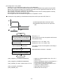
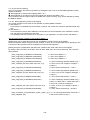
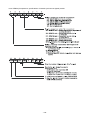
1-1. Setting up connections to a CPU
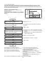
This LSI can be connected to four types of CPUs by changing the hardware settings.
Use the IF0 and IF1 terminals to change the settings and connect the CPU signal lines as follows.
Setting
status
IF1 IF0
L
L
L
H
H
L
H
H
CPU type
68000
H8
8086
Z80
CPU signal to connect to the 6045B terminals
terminal
+5V
terminal A0 terminal
R/
(GND)
(GND)
A0
terminal
READY
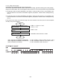
1-2. Address map
In this LSI, the control address range for each axis is independent. It is selected by using address input
terminal A3 and A4, as shown below. The internal map of each axis is defined by A0, A1 and A2
address line inputs.
A4
0
0
1
1
A3
0
1
0
1
Detail
X axis control address range
Y axis control address range
Z axis control address range
U axis control address range
-1-
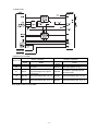
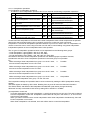
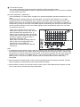
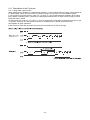
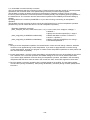
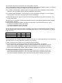
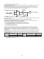
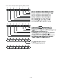
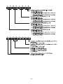
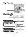
1-3. Examples of CPU interface circuits
1) Z80 mode
Note 1: If you will be using an interrupt controller, the PCL6045B also outputs an
signal as an
interrupt acknowledge signal to read the interrupt vector. When this signal is output, if the
terminal is pulled "L," it may output a
signal, in which case it cannot
PCL6045B's
receive a vector signal normally. Therefore, design it so that the decode circuit will function when
the
signal is "H."
Note 2: Pull up terminals D8 to D15 to +5V using an external resistance (5k to 10kohm). (Shared use of
one resistance for the 8 lines is available.)
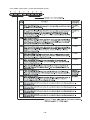
<Address map for Z80>
Writing operation
A2 to A0
Address
signal
000
COMB0
001
COMB1
010
OTPB
011
Reading operation
Address
signal
Detail
Control command
Detail
MSTSB0 Main status (bits 0 to 7)
Assign the axis
(specify a control command for
execution)
General-purpose output port
(only bits assigned as outputs
are effective)
MSTSB1 Main status (bits 8 to 15)
IOPB
General-purpose input/output port
(Invalid)
SSTSB
Sub status
100
BUFB0
Input/output buffer (bits 0 to 7)
BUFB0
Input/output buffer (bits 0 to 7)
101
BUFB1
Input/output buffer (bits 8 to 15)
BUFB1
Input/output buffer (bits 8 to 15)
110
BUFB2
Input/output buffer (bits 16 to 23) BUFB2
Input/output buffer (bits 11 to 23)
111
BUFB3
Input/output buffer (bits 24 to 31) BUFB3
Input/output buffer (bits 24 to 31)
Note: When writing a control command, the PCL refers axis assigning status. Therefore, specify axes to
use before writing a control command.
-2-
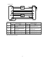
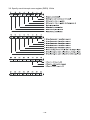
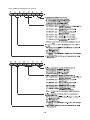
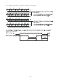
2) 8086 mode
< Address map for 8086>
Writing operation
A2 to A1
Address
signal
Reading operation
Address
signal
Detail
Axis assignment and control
command
General-purpose output port
(only bits assigned as outputs
are effective)
00
COMW
01
OTPW
10
BUFW0
Input/output buffer (bits 0 to 15)
11
BUFW1
Input/output buffer (bits 16 to 31) BUFW1
Note: Byte access is not possible.
-3-
Detail
MSTSW Main status (bits 0 to 15)
SSTSW
Sub status or general-purpose
input/output port
BUFW0
Input/output buffer (bits 0 to 15)
Input/output buffer (bits 16 to 31)
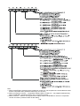
3) H8 mode
< Address map for H8 >
Writing operation
A2 to A0
Address
signal
Reading operation
Address
signal
Detail
Detail
11
COMW
Axis assignment and control
command
MSTSW Main status (bits 0 to 15)
10
OTPW
General-purpose output port
(only bits assigned as outputs
are effective)
SSTSW
Sub status or general-purpose
input/output port
01
BUFW0
Input/output buffer (bits 0 to 15)
BUFW0
Input/output buffer (bits 0 to 15)
00
BUFW1
Input/output buffer (bits 16 to 31) BUFW1
Note: Byte access is not possible.
-4-
Input/output buffer (bits 16 to 31)
4) 68000 mode
<Address map for 68000>
Writing operation
A2 to A0
Address
signal
Reading operation
Address
signal
Detail
Detail
11
COMW
Axis assignment and control
command
MSTSW Main status (bits 0 to 15)
10
OTPW
General-purpose output port
(only bits assigned as outputs
are effective)
SSTSW
Sub status or general-purpose
input/output port
01
BUFW0
Input/output buffer (bits 0 to 15)
BUFW0
Input/output buffer (bits 0 to 15)
00
BUFW1
Input/output buffer (bits 16 to 31) BUFW1
Note: Byte access is not possible.
-5-
Input/output buffer (bits 16 to 31)
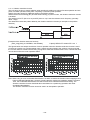
1-4. Examples of input/output interfaces
In order to prevent malfunctions that may be caused by electrical noise, and to protect the PCL, we
recommend isolating the circuits using photo-couplers.
If you don’t use photo-couplers, use some kind of protective circuit such as a TTL buffer. If the PCL's
terminals are led out directly to external circuits, the PCL may be destroyed by latching up or other
similar problems.
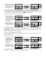
1)
, +EL, -EL, SD, ORG, and ALM input signals
Since these are not high-speed signals, general-purpose photo-couplers can be used.
The +EL and –EL signals’ logic can be changed by setting the ELL input. However, if a
disconnection occurs, it is safest to use NC (normal closed) contacts with negative logic (ELL = H).
2) +DR, -DR,
, PCS, CLR, LTC, and INP signal inputs
Since these are not high-speed signals, general-purpose photo-couplers can be used.
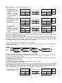
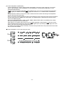
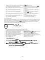
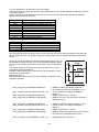
3) EA, EB, EZ, PA, and PB signal inputs
<When inputting an open-collector signal>
Since these are high-speed signals, you can use high-speed photo-couplers.
-6-
<When inputting line driver signals>
4) ERC and
output signals
Since these are high-speed signals, you can use high-speed photo-couplers.
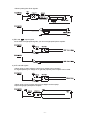
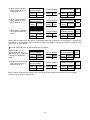
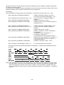
5) OUT and DIR signals
<When using an open-collector output (up to 10Kpps can be output)>
For signal speeds up to 10Kpps or so, general-purpose photo-couplers can be used.
<When using a photo-coupler output (up to 5Mpps can be output)>
Output using high-speed photo-couplers.
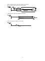
-7-
<With an isolated line-driver output (up to 5Mpps can be output)>
Drive a line-driver using output through a photo-coupler.
<When line driver output (up to 5Mpps can be output)>
<When TTL output (up to 5Mpps can be output)>
-8-
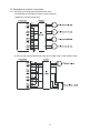
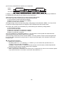
1-5. Examples of external connections
1-5-1. Connecting a manual pulser (External pulse input)
The following two methods are used to connect a pulser.
1) Method to connect to each axis
2) Use only one pulser and then select the axis to rotate using an axis selector switch.
-9-
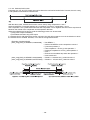
1-5-2. Connecting a DR switch
The following two methods are used to connect a DR switch.
However, if you will also be using a pulser (PA/PB), the DR switch has to share the PEn terminal.
Therefore, be careful when choosing a connection method.
1) Connect two DR switches for each axis
2) Connect an axis selection switch and two DR switches
- 10 -
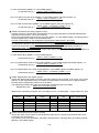
2. Software
2-1. Assumed environment for this description
CPU used
Data bus I/F
signal control
Reference clock
Number of axes controlled
Program language
8086
16-bit I/F
Used
19.6608 MHz
A total of 8 with 2 chips (2 x 4 axes: X, Y, Z, U)
MS-C
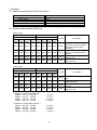
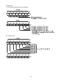
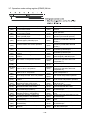
2-2. Address map and label definitions
[Write cycle]
Chip A
Address (HEX)
X
Y
Z
U
axis
axis
axis
axis
Chip B
Address (HEX)
X
Y
Z
U
axis
axis
axis
axis
Access
0300
0308
0310
0318
0320
0328
0330
0338
Word
0302
030A
0312
031A
0322
032A
0332
033A
Word
0304
030C
0304
031C
0324
032C
0334
033C
Word
0306
030E
0306
031E
0326
032E
0336
033E
Word
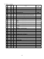
[Read cycle]
Chip A
Address (HEX)
X
Y
Z
U
axis
axis
axis
axis
Chip B
Address (HEX)
X
Y
Z
U
axis
axis
axis
axis
Access
0300
0308
0310
0318
0320
0328
0330
0338
Word
0302
030A
0312
031A
0322
032A
0332
033A
Word
0304
030C
0314
031C
0324
032C
0334
033C
Word
0306
030E
0316
031E
0326
032E
0336
033E
Word
/* Definition of Chip A base address */
#define AXS_AX 0x0300
#define AXS_AY 0x0308
#define AXS_AZ 0x0310
#define AXS_AU 0x0318
/* X axis */
/* Y axis */
/* Z axis */
/* U axis */
/* Definition of Chip B base address */
#define AXS_BX 0x0320
#define AXS_BY 0x0328
#define AXS_BZ 0x0330
#define AXS_BU 0x0338
/* X axis */
/* Y axis */
/* Z axis */
/* U axis */
- 11 -
Description
Write an axis selection (select
an axis for control command
execution) and a control
command
Write to an output port (only
effective on bits specified for
output)
Write to an input/output buffer
(bits 0 to 15)
Write to an input/output buffer
(bits 16 to 31)
Description
Read the main status (bits 0 to
15)
Read the sub status or an
input/output port
Read an input/output buffer (bits
0 to 15)
Reads an input/output buffer
(bits 16 to 31)
/* Definition of an operation command */
#define STAFL
0x0050
#define STAFH
0x0051
#define STAD
0x0052
#define STAUD
0x0053
#define CNTFL
0x0054
#define CNTFH
0x0055
#define CNTD
0x0056
#define CNTUD
0x0057
#define CMSTA
0x0006
#define SPSTA
0x002A
#define FCHGL
0x0040
#define FCHGH
0x0041
#define FSCHL
0x0042
#define FSCHH
0x0043
#define STOP
0x0049
#define SDSTP
0x004A
#define CMSTP
0x0007
#define CMEMG 0x0005
/* FL Start
/* FH Start
/* Down_only Start
/* Up/Down Start
/* FL Continue Start
/* FH Continue Start
/* Down only Continue Start
/* Up/Down Continue Start
/* Common Start
/* Spcial Common Start
/* Frq.Change to FL
/* Frq.Change to FH
/* Frq.Change to FL with U/D
/* Frq.Change to FH with U/D
/* Quick Stop
/* Down Stop
/* Common Stop
/* Emergency Stop
/* Definition of a general-purpose output bit control command */
#define P0RST
0x0010
/* P0 Reset to L
#define P1RST
0x0011
/* P1 Reset to L
#define P2RST
0x0012
/* P2 Reset to L
#define P3RST
0x0013
/* P3 Reset to L
#define P4RST
0x0014
/* P4 Reset to L
#define P5RST
0x0015
/* P5 Reset to L
#define P6RST
0x0016
/* P6 Reset to L
#define P7RST
0x0017
/* P7 Reset to L
#define P0SET
0x0018
/* P0 Set to H
#define P1SET
0x0019
/* P1 Set to H
#define P2SET
0x001A
/* P2 Set to H
#define P3SET
0x001B
/* P3 Set to H
#define P4SET
0x001C
/* P4 Set to H
#define P5SET
0x001D
/* P5 Set to H
#define P6SET
0x001E
/* P6 Set to H
#define P7SET
0x001F
/* P7 Set to H
/* Definition of a control command */
#define NOP
0x0000
#define SRST
0x0004
#define CUN1R
0x0020
#define CUN2R
0x0021
#define CUN3R
0x0022
#define CUN4R
0x0023
#define ERCOUT 0x0024
#define ERCRST 0x0025
#define PRECAN 0x0026
#define PCPCAN 0x0027
#define PRESHF 0x002B
#define PCPSHF 0x002C
#define PRSET
0x004F
#define STAON
0x0028
#define LTCH
0x0029
*/
*/
*/
*/
*/
*/
*/
*/
*/
*/
*/
*/
*/
*/
*/
*/
/* No Operation
/* Reset
/* Counter1 Reset
/* Counter2 Reset
/* Counter3 Reset
/* Counter4 Reset
/* ERC Output
/* ERC Reset
/* Mov.Pre-register Cancel
/* Cmp.Pre-register Cancel
/* Mov.Pre-register Shift
/* Cmp.Pre-register Shift
/* Mov.Pre-register Set
/* Positioning_Control Start
/* Counter Latch
- 12 -
*/
*/
*/
*/
*/
*/
*/
*/
*/
*/
*/
*/
*/
*/
*/
*/
*/
*/
*/
*/
*/
*/
*/
*/
*/
*/
*/
*/
*/
*/
*/
*/
*/
/* Definition of a register control command */
#define WPRMV 0x0080
#define WPRFL
0x0081
#define WPRFH 0x0082
#define WPRUR 0x0083
#define WPRDR 0x0084
#define WPRMG 0x0085
#define WPRDP 0x0086
#define WPRMD 0x0087
#define WPRIP
0x0088
#define WPRUS 0x0089
#define WPRDS 0x008A
#define WPRCP5 0x008B
#define WPRCI
0x008C
#define WRMV
0x0090
#define WRFL
0x0091
#define WRFH
0x0092
#define WRUR
0x0093
#define WRDR
0x0094
#define WRMG
0x0095
#define WRDP
0x0096
#define WRMD
0x0097
#define WRIP
0x0098
#define WRUS
0x0099
#define WRDS
0x009A
#define WRFA
0x009B
#define WRENV1 0x009C
#define WRENV2 0x009D
#define WRENV3 0x009E
#define WRENV4 0x009F
#define WRENV5 0x00A0
#define WRENV6 0x00A1
#define WRENV7 0x00A2
#define WRCUN1 0x00A3
#define WRCUN2 0x00A4
#define WRCUN3 0x00A5
#define WRCUN4 0x00A6
#define WRCMP1 0x00A7
#define WRCMP2 0x00A8
#define WRCMP3 0x00A9
#define WRCMP4 0x00AA
#define WRCMP5 0x00AB
#define WRIRQ
0x00AC
#define WRCI
0x00BC
#define RPRMV 0x00C0
#define RPRFL
0x00C1
#define RPRFH
0x00C2
#define RPRUR
0x00C3
#define RPRDR
0x00C4
#define RPRMG 0x00C5
#define RPRDP
0x00C6
#define RPRMD 0x00C7
#define RPRIP
0x00C8
#define RPRUS
0x00C9
#define RPRDS
0x00CA
#define RPRCP5 0x00CB
#define RPRCI
0x00CC
#define RRMV
0x00D0
#define RRFL
0x00D1
#define RRFH
0x00D2
#define RRUR
0x00D3
#define RRDR
0x00D4
#define RRMG
0x00D5
/* Write to PRMV Pre-register */
/* Write to PRFL Pre-register
*/
/* Write to PRFH Pre-register
*/
/* Write to PRUR Pre-register
*/
/* Write to PRDR Pre-register
*/
/* Write to PRMG Pre-register
*/
/* Write to PRDP Pre-register
*/
/* Write to PRMD Pre-register
*/
/* Write to PRIP Pre-register
*/
/* Write to PRUS Pre-register
*/
/* Write to PRDS Pre-register
*/
/* Write to PRCP5 Pre-register */
/* Write to PRCI Pre-register
*/
/* Write to RMV Register
*/
/* Write to RFL Register
*/
/* Write to RFH Register
*/
/* Write to RUR Register
*/
/* Write to RDR Register
*/
/* Write to RMG Register
*/
/* Write to RDP Register
*/
/* Write to RMD Register
*/
/* Write to RIP Register
*/
/* Write to RUS Register
*/
/* Write to RDS Register
*/
/* Write to RFA Register
*/
/* Write to RENV1 Register
*/
/* Write to RENV2 Register
*/
/* Write to RENV3 Register
*/
/* Write to RENV4 Register
*/
/* Write to RENV5 Register
*/
/* Write to RENV6 Register
*/
/* Write to RENV7 Register
*/
/* Write to RCUN1 Register
*/
/* Write to RCUN2 Register
*/
/* Write to RCUN3 Register
*/
/* Write to RCUN4 Register
*/
/* Write to RCMP1 Register
*/
/* Write to RCMP2 Register
*/
/* Write to RCMP3 Register
*/
/* Write to RCMP4 Register
*/
/* Write to RCMP5 Register
*/
/* Write to RIRQ Register
*/
/* Write to RCI Register
*/
/* Read from PRMV Pre-register */
/* Read from PRFL Pre-register */
/* Read from PRFH Pre-register */
/* Read from PRUR Pre-register */
/* Read from PRDR Pre-register */
/* Read from PRMG Pre-register */
/* Read from PRDP Pre-register */
/* Read from PRMD Pre-register */
/* Read from PRIP Pre-register */
/* Read from PRUS Pre-register */
/* Read from PRDS Pre-register */
/* Read from PRCP5 Pre-register */
/* Read from PRCI Pre-register */
/* Read from RMV Register
*/
/* Read from RFL Register
*/
/* Read from RFH Register
*/
/* Read from RUR Register
*/
/* Read from RDR Register
*/
/* Read from RMG Register
*/
- 13 -
#define
#define
#define
#define
#define
#define
#define
#define
#define
#define
#define
#define
#define
#define
#define
#define
#define
#define
#define
#define
#define
#define
#define
#define
#define
#define
#define
#define
#define
#define
#define
#define
#define
#define
#define
#define
RRDP
RRMD
RRIP
RRUS
RRDS
RRFA
RRENV1
RRENV2
RRENV3
RRENV4
RRENV5
RRENV6
RRENV7
RRCUN1
RRCUN2
RRCUN3
RRCUN4
RRCMP1
RRCMP2
RRCMP3
RRCMP4
RRCMP5
RRIRQ
RRLTC1
RRLTC2
RRLTC3
RRLTC4
RRSTS
RREST
RRIST
RRPLS
RRSPD
RRSDC
RRCI
RRCIC
RRIPS
0x00D6
0x00D7
0x00D8
0x00D9
0x00DA
0x00DB
0x00DC
0x00DD
0x00DE
0x00DF
0x00E0
0x00E1
0x00E2
0x00E3
0x00E4
0x00E5
0x00E6
0x00E7
0x00E8
0x00E9
0x00EA
0x00EB
0x00EC
0x00ED
0x00EE
0x00EF
0x00F0
0x00F1
0x00F2
0x00F3
0x00F4
0x00F5
0x00F6
0x00FC
0x00FD
0x00FF
/* Definition of an axis selection code */
#define SEL_X
0x0100
#define SEL_Y
0x0200
#define SEL_Z
0x0400
#define SEL_U
0x0800
/* Read from RDP Register
/* Read from RMD Register
/* Read from RIP Register
/* Read from RUS Register
/* Read from RDS Register
/* Read from RFA Register
/* Read from RENV1 Register
/* Read from RENV2 Register
/* Read from RENV3 Register
/* Read from RENV4 Register
/* Read from RENV5 Register
/* Read from RENV6 Register
/* Read from RENV7 Register
/* Read from RCUN1 Register
/* Read from RCUN2 Register
/* Read from RCUN3 Register
/* Read from RCUN4 Register
/* Read from RCMP1 Register
/* Read from RCMP2 Register
/* Read from RCMP3 Register
/* Read from RCMP4 Register
/* Read from RCMP5 Register
/* Read from RIRQ Register
/* Read from RLTC1 Register
/* Read from RLTC2 Register
/* Read from RLTC3 Register
/* Read from RLTC4 Register
/* Read from RSTS Register
/* Read from REST Register
/* Read from RIST Register
/* Read from RPLS Register
/* Read from RSPD Register
/* Read from RSDC Register
/* Read from RCI Register
/* Read from RCIC Register
/* Read from RIPS Register
*/
*/
*/
*/
*/
*/
*/
*/
*/
*/
*/
*/
*/
*/
*/
*/
*/
*/
*/
*/
*/
*/
*/
*/
*/
*/
*/
*/
*/
*/
*/
*/
*/
*/
*/
*/
/* X Select Code
/* Y Select Code
/* Z Select Code
/* U Select Code
*/
*/
*/
*/
- 14 -
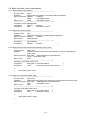
2-3. Basic functions used in descriptions
2-3-1. Word output function (outpw)
/*------------------------------------------------------------------------Function name:
outpw
Operation:
Writes word data (wdata) to a specified address (address)
Dummy argument: address
--- Address
wdata
--- Word data to write
Return value:
wdata
--- Word data to write
-------------------------------------------------------------------------*/
unsigned int outpw (address,data)
unsigned int
address; /* Address
*/
unsigned int
data;
/* Word data to write */
2-3-2. Word input function (inpw)
/*-----------------------------------------------------------------------Function name:
inpw
Operation:
Reads word data from a specified address (address)
Dummy argument: address
--- Address
Return value:
Word data read
------------------------------------------------------------------------*/
unsigned int
inpw (address)
unsigned int
address; /* Address
*/
2-3-3. Write the command code and axis selection (p645_wcom)
/*-----------------------------------------------------------------------Function name:
p645_wcom
Operation:
Writes a command code and an axis selection (comw) to a specified axis
(base_addr).
Dummy argument: base_addr --- Base address of the specified axis
comw --- Word data to write
Return value:
None
------------------------------------------------------------------------*/
void p645_wcom (base_addr,comw)
unsigned int
base_addr; /* Axis base address
*/
unsigned int
comw;
/* Command code and axis selection
*/
{
outpw (base_addr, comw);
}
2-3-4. Write to an output port (p645_wotp)
/*-----------------------------------------------------------------------Function name:
p645_wotp
Operation:
Writes word data (otpw) to the output port of the specified axis (base_addr).
Dummy argument: base_addr --- Base address of the specified axis
otpw
--- Word data to write
Return value:
None
------------------------------------------------------------------------*/
void p645_wotp (base_addr, otpw)
unsigned int
base_addr; /* Axis base address
*/
unsigned int
otpw;
/* Word data to write
*/
{
outpw (base_addr+2, otpw);
}
- 15 -
2-3-5. Read status (p645_rsts)
/*-----------------------------------------------------------------------Function name:
p645_rsts
Operation:
Reads the status of the specified axis (base_addr)
Dummy argument: base_addr --- Base address of the specified axis
Return value:
Data read
------------------------------------------------------------------------*/
unsigned long
p645_rsts (base_addr)
unsigned int
base_addr;
/* Axis base address */
{
union udata{
unsigned long ldata;
unsigned int
idata[2];
}udt;
udt.idata[0] = inpw (base_addr);
/* Main status
*/
udt.idata[1] = inpw (base_addr+2); /* Sub status, input/output port */
return(udt. ldata);
}
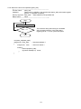
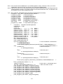
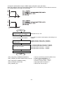
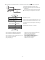
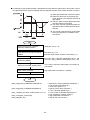
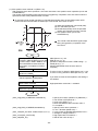
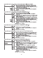
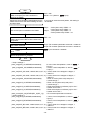
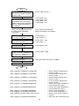
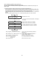
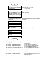
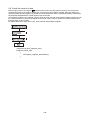
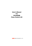
2-3-6. Write register (p645_wreg)
/*-------------------------------------------------------------------------Function name:
p645_wreg
Operation:
Writes data (data) to the specified register in the specified axis (base_addr)
Dummy argument: base_addr --- Base address of the specified axis
rwcom
--- Register write command
data
--- Data to write
Return value:
None
--------------------------------------------------------------------------*/
Start
Write 4 bytes of data to
an input/output buffer
Any order can be used for writing to the input/output buffer.
Write a "register write
command"
For details about register write commands, see section "3-3. List
of commands."
End
void p645_wreg(base_addr,rwcom,data)
unsigned int base_addr;
/* Axis base address
*/
unsigned int rwcom;
/* Register write command */
unsigned long data;
/* Data to write
*/
{
union udata{
unsigned long
unsigned int
ldata;
idata[2];
}udt;
udt.ldata = data;
outpw (base_addr+4, udt. idata[0]);
outpw (base_addr+6, udt. idata[1]);
outpw (base_addr, rwcom);
/* Write to an input/output buffer (bits 0 to 15)
/* Write to an input/output buffer (bits 16 to 31)
/* Write command
}
- 16 -
*/
*/
*/
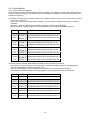
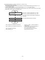
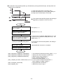
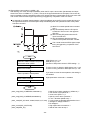
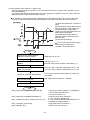
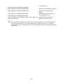
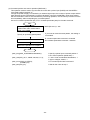
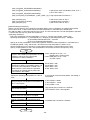
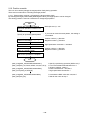
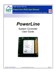
2-3-7. Read register (p645_rreg)
/*-------------------------------------------------------------------------Function name:
p645_rreg
Operation:
Reads contents of the register for the axis that was specified (base_addr)
Dummy argument: base_addr --- Base address of the specified axis
rrcom
--- Reigster read command
Return value:
Read data
--------------------------------------------------------------------------*/
Start
Write register read
command
For details about register read commands, see section "3-3.
List of commands."
Read 4 bytes of data
from the input/output
buffer"
Any order can be used for reading input/output buffer.
End
unsigned long p645_rreg (base_addr, rrcom)
unsigned int base_addr;
/* Axis base address
unsigned int rrcom;
/* Register write command
*/
*/
{
union udata{
unsigned long ldata;
unsigned int
idata[2];
}udt;
outpw(base_addr, rrcom);
udt.idata[0] = inpw (base_addr+4);
udt.idata[1] = inpw (base_addr+6);
return(udt. ldata);
/* Write a register read command
*/
/* Read input/output buffer (bits 0 to 15) */
/* Read the input/output buffer (bits 16 to 31) */
}
- 17 -
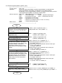
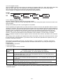
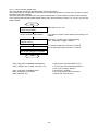
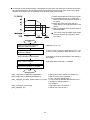
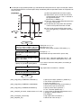
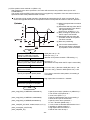
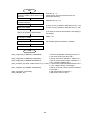
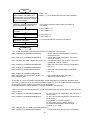
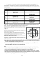
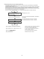
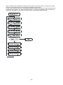
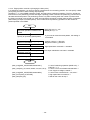
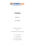
2-3-8. Wait for the end of the operation (p645_wait)
/*-------------------------------------------------------------------------Function name:
p645_wait
Operation:
Waits until bit 3 (SEND) in the specified axis (base_addr) main status register
goes to "1" (operation complete).
Dummy argument: base_addr --- Base address of the specified axis
Return value:
None
--------------------------------------------------------------------------*/
Start
Read main status
N
Bit 3 = 1 ?
Y
The maximum delay after writing an immediate
stop command until bit 3 in the main status
register goes to "1" is one cycle at FH speed.
End
void p645_wait(base_addr)
unsigned int base_addr;
{
unsigned int msts;
/* Axis base address */
/* Axis main status */
while(1){
msts=inpw(base_addr);
If((msts & 0x0008)!=0) break;
}
}
- 18 -
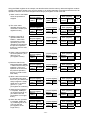
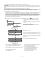
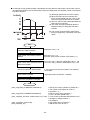
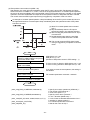
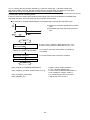
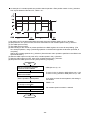
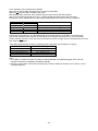
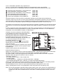
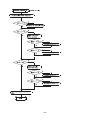
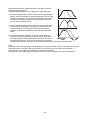
2-4. Set the speed pattern (p645_vset)
/*-------------------------------------------------------------------------Function name:
p645_vset
Operation:
Specify the initial speed (fldata), operation speed (fhdata), acceleration time
(utime), deceleration time (dtime), acceleration S-curve range (usdata),
deceleration S-curve range (dsdata), selection of a linear/S-curve (curve), and the
compensated speed (fadata), and write the speed pattern.
Dummy argument: base_addr --- Base address of the specified axis
fldata
--- Initial speed (pps)
fhdata --- Operation speed (pps)
utime
--- Acceleration time (ms)
dtime --- Deceleration time (ms)
usdata
--- Acceleration S-curve range
dsdata
--- Deceleration S-curve range
curve
--- Selection of a linear/S-curve (L: Linear, S: S-curve)
fadata
--- Compensated speed (pps)
Return value:
None
--------------------------------------------------------------------------*/
Start
Select a magnification rate for the value
of "fhdata," and set PRMG. Magnification
rates are: 1x, 2x, 3x, 4x, 5x, 10x, 20x,
50x, or 100x.
PRMG = (300 / magnification rate) – 1
Magnification rate = 300 / (PRMG + 1)
Calculate the "PRFL" value to match the
magnification rate.
PRFL = (fldata) / magnification rate
= (fldata) / (300 / (PRMG + 1))
Calculates "PRFH" set value matching
with the magnification rate.
PRFH = (fhdata) / magnification rate
= (fhdata) / (300/(PRMG + 1))
Calculate the acceleration rate PRUR
from the acceleration time (utime), PRFL
and PRFH settings, acceleration /
deceleration method (curve: S-curve /
linear), and S-curve acceleration range
(usdata).
PRUR =((utime) x 10-3 x 19660800 / a) - 1
1) When using linear acceleration (curve = L)
a = (PRFH - PRFL) x 4
2) When using S-curve acceleration without a linear part
(curve = S & usdata=0)
a = (PRFH - PRFL) x 8
3) When using S-curve acceleration with a linear part
(curve = S & usdata>0)
a = (PRFH - PRFL+2 x usdata) x 4
Calculate the PRDR deceleration rate
from the deceleration time (dtime), PRFL
and PRFH settings, the acceleration /
deceleration method (curve: S-curve /
linear), and the S-curve deceleration
range (dsdata).
PRDR = ((dtime) x 10-3 x 19660800 / b) - 1
1) When using linear deceleration (curve=L)
b = (PRFH - PRFL) x 4
2) When using S-curve deceleration without a linear part
(curve = S & dsdata=0)
b = (PRFH - PRFL) x 8
3) When using S-curve deceleration with a linear part
(curve = S & dsdata>0)
b = (PRFH - PRFL+2 x dsdata) x 4
Calculate the RFA set value to match the
magnification rate
RFA
= (fadata) / magnification rate
= (fadata) / (300 / (PRMG + 1))
Write PRFL, PRFH, PRMG, PRUR,
PRDR, PRUS, PRDS, RFA, and PRMD.
When the curve = L (linear), MSMD (bit 10) of PRMD = 0
When the curve = S (S-curve), MSMD (bit 10) of PRMD = 1
End
- 19 -
Note 1: This function sets the MSMD (bit 10) in PRMD (operation mode). Therefore, when you write to
PRMD after using this function, be careful not to change the MSMD setting.
Note 2: With this function, the LSI automatically selects the lowest magnification rate that will generate the
speed specified in "fhdata." If you want a shorter acceleration/deceleration time, a modification will
be needed to force a higher magnification rate.
void p645_vset(base_addr,fldata,fhdata,utime,dtime,usdata,dsdata,carv,fadata)
unsigned int base_addr /* Specified axis base address */
unsigned long fldata
/* Initial speed (pps) */
unsigned long fhdata
/* Operation speed (pps) */
unsigned long utime
/* Acceleration time (ms) */
unsigned long dtime
/* Deceleration time (ms) */
unsigned int usdata
/* Acceleration S-curve range */
unsigned int dsdata
/* Deceleration S-curve range */
char curve
/* L: linear S: S-curve */
unsigned long fadata /* Compensated speed (pps) */
{
unsigned int rfldt,rfhdt,rurdt,rdrdt,rmgdt,rfadt;
unsigned long rmddt;
double a,b;
rmgdt = 299;
/* x1 Mode */
if(fhdata>65535L) rmgdt = 149; /* x2 Mode */
if(fhdata>131070L) rmgdt = 99; /* x3 Mode */
if(fhdata>196605L) rmgdt = 74; /* x4 Mode */
if(fhdata>262140L) rmgdt = 59; /* x5 Mode */
if(fhdata>327675L) rmgdt = 29; /* x10 Mode */
if(fhdata>655350L) rmgdt = 14; /* x20 Mode */
if(fhdata>1310700L) rmgdt = 5;
/* x50 Mode */
if(fhdata>3276750L) rmgdt = 2;
/* x100 Mode */
rfldt = fldata/(300/(rmgdt+1));
rfhdt = fhdata/(300/(rmgdt+1));
rfadt = fadata/(300/(rmgdt+1));
if((curve=='L')||(curve=='l')){
/* Linear acceleration / deceleration*/
a = (double)((rfhdt-rfldt)*4);
b = (double)((rfhdt-rfldt)*4);
rmddt = p645_rreg(base_addr,0x00C7)& 0xFFFFFBFF; /* RMD MSMD(Bit10)=0 */
else{
/* S-curve acceleration/deceleration */
if(usdata==0){
/* Without linear part */
a = (double)((rfhdt-rfldt)*8);
}
else {
/* With linear part */
a = (double)((rfhdt-rfldt+2*usdata)*4);
}
if(dsdata==0){
/* Without linear part */
b = (double)((rfhdt-rfldt)*8);
}
else {
/* With linear part */
b = (double)((rfhdt-rfldt+2*dsdata)*4);
}
rmddt = p645_rreg(base_addr,0x00C7) | 0x00000400;/* RMD MSMD(Bit10)=1 */
}
rurdt = ((double)utime*19660.8 / a ) - 1.0;
if(dtime==0) rdrdt =0;
/* When rdrdt = 0, deceleration rate*/
else rdrdt = ((double)dtime*19660.8 / b ) - 1.0;
/* will the set value of rurdt.*/
p645_wreg(base_addr, WPRFL, (unsigned long)rfldt);
p645_wreg(base_addr, WPRFH, (unsigned long)rfhdt);
p645_wreg(base_addr, WPRUR, (unsigned long)rurdt);
p645_wreg(base_addr, WPRDR, (unsigned long)rdrdt);
p645_wreg(base_addr, WPRMG, (unsigned long)rmgdt);
p645_wreg(base_addr, WPRDP, (unsigned long)usdata);
p645_wreg(base_addr, WPRDS, (unsigned long)dsdata);
p645_wreg(base_addr, WPRMD, rmddt);
p645_wreg(base_addr, WRFA, (unsigned long)rfadt);
}
- 20 -
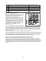
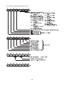
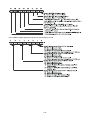
2-5. Control Method
2-5-1. How to access the registers
There are two methods to write/read data to/from the registers. The difference between these two methods is
in how to create the software. The mixed use of the two methods is possible. (The program examples in this
manual use method 1.)
1) Consider the writing of a command and the input or output of data as one set. Then, use an area of memory
that covers 4 sets in all.
In this case, except for the interpolation operation, you can use 00h to specify the axis for a command
(COMB1).
However, in order to start/stop an interpolation operation, an axis must be specified.
With this method, a simple program can be created easily when multiple PCL6045Bs are used.
A4 to A0
Symbol
Description
0000
COMW_X
Command for the X axis
0010
BUFW0_X
Input/output buffer for the X axis (bits 0 to 15)
0011
BUFW1_X
Input/output buffer for the X axis (bits 16 to 31)
0100
COMW_Y
Command for the Y axis
0110
BUFW0_Y
Input/output buffer for the Y axis (bits 0 to 15)
0111
BUFW1_Y
Input/output buffer for the Y axis (bits 16 to 31)
1000
COMW_Z
Command for the Z axis
1010
BUFW0_Z
Input/output buffer for the Z axis (bits 0 to 15)
1011
BUFW1_Z
Input/output buffer for the Z axis (bits 16 to 31)
1100
COMW_U
Command for the U axis
1110
BUFW0_U
Input/output buffer for the U axis (bits 0 to 15)
1111
BUFW1_U
Input/output buffer for the U axis (bits 16 to 31)
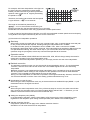
2) Use the shared command write address and data input/output area for each axis.
In this case, you have to specify an axis each time a command is written. (However, a software reset
command SRST does not need to specify an axis.)
When one PCL6045B is used, an interpolation command can be used the same as above.
This method can write/read data to the same register of any connected axis with one command.
A4 to A1
Symbol
Description
0000
COMW
Command
0010
BUFW0_X Input/output buffer for the X axis (bits 0 to 15)
0011
BUFW1_X Input/output buffer for the X axis (bits 16 to 31)
0110
BUFW0_Y Input/output buffer for the Y axis (bits 0 to 15)
0111
BUFW1_Y Input/output buffer for the Y axis (bits 16 to 31)
1010
BUFW0_Z Input/output buffer for the Z axis (bits 0 to 15)
1011
BUFW1_Z Input/output buffer for the Z axis (bits 16 to 31)
1110
BUFW0_U Input/output buffer for the U axis (bits 0 to 15)
1111
BUFW1_U Input/output buffer for the U axis (bits 16 to 31)
- 21 -
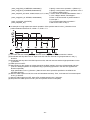
2-5-2. Pre-register function
The pre-registers consist of three groups: the operation pre-registers (RMV, RFL, RFH, RUR, RDR, RMG, RDP,
RMD, RIP, RUS, RDS, RCI), the comparator 5 pre-register (RCMP5) and start command pre-register.
This LSI has the following 2-layer structure and executes FIFO operation.
The pre-register is a register to store next operation data during operation.
2-5-2-1. Basic pre-register operation
Normally, operation data are written into the 2nd pre-register.
When you need to modify the current operating status, such as to change the speed, write the new data in the
2nd pre-register.
Writing to and reading from the 1st pre-register is not possible.
Use the operation pre-register when you want the motor to continue on to the next operation when the current
operation is complete. This is done by writing the new data for the next operation while the current operation is
executing. However, sometimes new data must be written to more than one pre-register to prepare for the next
operation, and it is possible that the operation currently being executed will end while still writing the new
operation data. In this case, the motor may malfunction if the new data is still being written. To prevent this
problem, a function has been added to the PCL6045B to confirm whether or not the writing is complete.
When new data are written into the pre-register, the PCL stores the data. However, the status is not confirmed
at first.
After writing to all the operation pre-registers that need to be rewritten, write a start command to the PCL. Now
the PCL will have a confirmed status. If you want the PCL to do the same operation as the previous one, you
just write a new start command.
Data transfer (copy) details for the PCL: (2nd pre-register) -> (1st pre-register) -> (register); varies with 2
pre-register confirmation status (PFM) bits that are controlled inside the PCL chip. They will change in the
following order.
a. Write start/stop commands.
b. End of operation
c. Write a pre-register control command
Pre-register
confirmation
status
0
1
2
3
Pre-register vacant status, data transfer (copy) details
(2Pr = 2nd pre-register, 1Pr =1st pre-register, Rg = Register)
None of the register data is fixed. When data is written into the 2Pr, the PCL transfers
the data as follows: 2Pr -> 1Pr -> Rg. The contents of the 2Pr, 1Pr, and Rg are all the
same as the data written to the 2Pr.
The status of the Rg is fixed, but the 2Pr and 1Pr are not yet fixed. When data is written
into 2Pr, the PCL transfers the data as follows: 2Pr -> 1Pr. The data in 2Pr and 1Pr will
be the same.
The status of the Rg and 1Pr are fixed, but 2Pr is not.
When data is written into the 2Pr, it is only written into 2Pr, not into the 1Pr or Rg.
The status of the 2Pr, 1Pr, and Rg is not fixed. You cannot write data to 2Pr.
In this condition SPRF (bit 14) in MSTS goes to "1."
The status of the data in the pre-registers (fixed or not) can be checked by reading PFM0 to 1 (bits 20, 21) of
the RSTS register.
- 22 -
Using the PRMV register as an example, we describe below how the memory status and register contents
change when data is written to the 2nd pre-register, or by writing start/stop commands and at the end of an
operation. We also cover what changes when writing a pre-register control command.
1) Write "1000" to the PRMV
when the operation is
stopped
PRMV
(2nd pre-register)
Memory
Not fixed
status
Content
1000
2) The motor starts
operation when a start
command is written (The
register is fixed.)
PRMV
(2nd pre-register)
Memory
Not fixed
status
Content
1000
3) Write the next set of
operation data when
PRMV = -5000 while
executing the current
operation. (If the next
operation is the same as
the previous operation,
there is no need to write
fresh data.)
PRMV
(2nd pre-register)
Memory
Not fixed
status
Content
-5000
4) Write a start command for
the next operation. (The
data in the 1st
pre-register is fixed.)
PRMV
(2nd pre-register)
Memory
Not fixed
status
Content
-5000
5) Write the data for two
steps ahead when PRMV
= 3000 while executing an
operation. (If the next
operation is the same as
the previous operation,
there is no need to write
fresh data.)
PRMV
(2nd pre-register)
Memory
Not fixed
status
Content
3000
6) Write a start command for PRMV
the operation two steps
(2nd pre-register)
from now. (The data in the Memory
Fixed
2nd pre-register is fixed.)
status
SPRF (bit 14) in MSTS
Content
3000
goes to "1." (The
pre-register full condition.)
7) When the first operation
is complete, SPRF (bit
14) in MSTS goes to "0."
(The data in the 2nd
pre-register in no longer
fixed.)
PRMV
(2nd pre-register)
Memory
Not fixed
status
Content
3000
8) When the next operation
is complete, SPRF (bit
14) in MSTS goes to "0."
(The 1st and 2nd
pre-registers are no
longer fixed.)
PRMV
(2nd pre-register)
Memory
Not fixed
status
Content
3000
(1st pre-register)
Memory
status
Content
Not
fixed
1000
(1st pre-register)
Memory
status
Content
Not
fixed
1000
(1st pre-register)
Memory
status
Content
Not
fixed
-5000
(1st pre-register)
Memory
status
Content
Fixed
-5000
(1st pre-register)
Memory
status
Content
Fixed
-5000
(1st pre-register)
Memory
status
Content
Fixed
-5000
(1st pre-register)
Memory
status
Content
Fixed
3000
(1st pre-register)
Memory
status
Content
- 23 -
Not
fixed
3000
RMV (register)
PFM
Memory
Not fixed
status
Content
1000
0
RMV (register)
PFM
Memory
status
Content
Fixed
1000
RMV (register)
Memory
status
Content
Fixed
Fixed
Fixed
Fixed
Fixed
PFM
2
PFM
3
PFM
2
-5000
RMV (register)
Memory
status
Content
2
1000
RMV (register)
Memory
status
Content
PFM
1000
RMV (register)
Memory
status
Content
1
1000
RMV (register)
Memory
status
Content
PFM
1000
RMV (register)
Memory
status
Content
1
Fixed
3000
PFM
1
9) After the third operation is
complete. SPRF (bit 14)
in MSTS goes to "0." (The
data in all of the registers
is no longer fixed.)
PRMV
(2nd pre-register)
Memory
Not fixed
status
Content
3000
(1st pre-register)
Memory
status
Content
Not
fixed
3000
RMV (register)
PFM
Memory
Not fixed
status
Content
3000
0
The status of the data can be checked by seeing PRM0 to 1 of the extension status register (RSTS). If PFM=3,
you can check the status of the data by reading the SPRF bit in the main status register (MSTS).
Also, set IRNM <bit 2> to "1" in the RIRQ (event interrupt cause), and when the status of the 2nd pre-register
changes from fixed to not fixed (ready to write data), an
signal will be output.
A Stop command is written or an error stops the operation
Execute steps 1) to 6)
above (The data in the
2nd pre-register will be
stored in memory.) SPRF
(bit 14) in MSTS goes to
"1." (The pre-registers
are all fixed.)
7) A stop command is
written or an error stops
the operation. SPRF (bit
14) in MSTS goes to "0."
PRMV
(2nd pre-register)
Memory
Fixed
status
Content
3000
PRMV
(2nd pre-register)
Memory
Not fixed
status
Content
3000
(1st pre-register)
Memory
status
Content
Fixed
-5000
(1st pre-register)
Memory
status
Content
Not
fixed
-5000
RMV (register)
Memory
status
Content
Fixed
PFM
3
1000
RMV (register)
PFM
Memory
Not fixed
status
Content
1000
0
When a stop command is written, or the operation is stopped by an error, the PCL does not shift any data in
the registers and PFM goes to “0." Therefore, when the next start command is written in step 7) above, RMV
will go to "1000."
Be careful. If a deceleration stop command is written during deceleration, the pre-registers are not canceled,
and the PCL will continue with the next operation.
2-5-2-2. Pre-register operation control commands
Data shift and cancel commands are available for the operation pre-registers. The function of these two
commands is as follows.
Shift command for operation pre-registers (2Bh)
Execute steps from 1) to
6) above. (The 2nd
pre-register is fixed.)
SPRF (bit 14) in MSTS
goes to "1". (The
pre-register full
condition.)
7) Write a shift command
(2bh). SPRF (bit 14) in
MSTS goes to "1." (The
pre-register full condition.)
PRMV
(2nd pre-register)
Memory
Fixed
status
Content
3000
PRMV
(2nd pre-register)
Memory
Fixed
status
Content
3000
(1st pre-register)
Memory
status
Content
Fixed
-5000
(1st pre-register)
Memory
status
Content
Fixed
3000
RMV (register)
Memory
status
Content
Fixed
3
1000
RMV (register)
Memory
status
Content
PFM
Fixed
PFM
3
-5000
A shift command (2Bh) transfers data (copy) in the following order 1st pre-register -> register, and then 2nd
pre-register -> 1st pre-register. The memory status does not change.
- 24 -
Pre-register cancel operation command (26h)
Execute steps from 1)
to 6) above. (The data
in the 2nd pre-register
is fixed.)
SPRF (bit 14) in MSTS
goes to "1." (The data
in the pre-registers are
all fixed.)
PRMV
(2nd pre-register)
Memory
Fixed
status
Content
3000
7) Write a cancel command
(26h). SPRF (bit 14) in
MSTS goes to "0." (The
data in the 1st
pre-register is not fixed.)
PRMV
(2nd pre-register)
Memory
Not fixed
status
Content
3000
8) The 1st operation
completes.
SPRF (bit 14) in MSTS
goes to "0." (The data in
all the pre-registers is not
fixed.)
PRMV
(2nd pre-register)
Memory
Not fixed
status
Content
3000
(1st pre-register)
Memory
status
Content
Fixed
-5000
(1st pre-register)
Memory
status
Content
Not
fixed
-5000
(1st pre-register)
Memory
status
Content
Not
fixed
3000
RMV (register)
Memory
status
Content
Fixed
3
1000
RMV (register)
Memory
status
Content
PFM
Fixed
PFM
1
1000
RMV (register)
PFM
Memory
Not fixed
status
Content
-5000
0
The cancel command (26h) cancels the start commands for the next operation and the operation after that.
These start commands were written to fix the data in the 2nd and 1st pre-registers. However, the data will not
change when a cancel command is issued.
Therefore, when the 1st operation completes at step 7) above, the PCL will transfer the data as follows: 1st
pre-register -> register, 2nd pre-register -> 1st pre-register; and the status is as shown in step 8) above. Since
the start command for the next operation is canceled, the PCL will not start automatically. However, if another
start command is written, the PCL will enter RMV=-5000 operation.
2-5-2-3. Basic pre-register (PRCP5) operation for comparator 5
Comparator 5 (RCMP5) has pre-registers. Like the operation pre-registers, they have a two-step configuration
and work in FIFO order.
Normally, write data for comparator 5 to the 2nd pre-register (PRCP5).
In order to change current comparison value, you must write new data to the register (RCMP5). You cannot
write to or read from the 1st pre-register.
Data transfer (copy) of comparator data: (2nd pre-register) -> (1st pre-register) -> (register). This transfer can
be done using the following steps.
a. Write data to the 2nd pre-register
b. Change the comparator data comparison condition from enable -> disable
c. Write a pre-register control command
Each time data is written to the 2nd pre-register, the 1st pre-register memory status can be confirmed and then
the 2nd pre-register can be checked. The memory status (PFC) can be checked by reading the RSTS register.
Below we describe the memory status of the comparator data. The PFC register is used to monitor the data
status. By reading the RSTS register, you can check the status of the data (fixed or not).
1) Write "1000" to PRCP5
(register is fixed)
PRCP5
(2nd pre-register)
Memory
Not fixed
status
Content
1000
(1st pre-register)
RCMP5 (register)
Memory
status
Content
Memory
status
Content
- 25 -
Not
fixed
1000
Fixed
1000
PFC
1
2) Write "2000" to PRCP5
(the data in the 1st
pre-register will be fixed.)
PRCP5
(2nd pre-register)
Memory
Not fixed
status
Content
2000
3) Write "3000" to PRCP5
(the data in the 2nd
pre-register will be fixed.)
SPDF (bit 15) in MSTS
goes to "1." (Pre-register
full condition.)
PRCP5
(2nd pre-register)
Memory
Fixed
status
Content
3000
4) When RCMP = 1000, the
PCL will change the
comparison condition for
comparator 5 from
enabled -> disabled.
SPDF (bit 15) in MSTS
goes to "0." (Data can be
written to the
pre-registers.)
PRCP5
(2nd pre-register)
Memory Not fixed
status
Content
3000
5) When RCMP = 2000, the
PCL will change the
comparison condition for
comparator 5 from
enabled -> disabled.
PRCP5
(2nd pre-register)
Memory
Not fixed
status
Content
3000
6) With RCMP = 3000, the
PCL will change the
comparison condition for
comparator 5 from
enabled -> disabled.
PRCP5
(2nd pre-register)
Memory
Not fixed
status
Content
3000
(1st pre-register)
RCMP5 (register)
Memory
status
Content
Memory
status
Content
Fixed
2000
Fixed
RCMP5 (register)
Memory
status
Content
Memory
status
Content
2000
Fixed
RCMP5 (register)
Memory
status
Content
Memory
status
Content
3000
Fixed
3
PFC
2
2000
(1st pre-register)
RCMP5 (register)
Memory
status
Content
Memory
status
Content
Not
fixed
3000
PFC
1000
(1st pre-register)
Fixed
2
1000
(1st pre-register)
Fixed
PFC
Fixed
PFC
1
3000
(1st pre-register)
RCMP5 (register)
PFC
Memory
status
Content
Memory
Not fixed
status
Content
3000
0
Not
fixed
3000
The data status (PFC value) can be checked by setting PFC0 to 1 in the RSTS register to 1, and when PFC is
3, SPDF in the main status (MSTS) will go to "1".
Also, set IRND <bit 3> to "1" in the RIRQ (event interrupt cause) register. When the 2nd pre-register changes
signal can be output.
from fixed to not fixed (ready to write data), an
2-5-2-4. Pre-register control command for comparator 5
The comparator 5 pre-register can be manipulated with data shift and cancel commands. Their functions are
as follows.
Shift command for the comparator 5 pre-register (2Ch)
Execute steps 1) to 3)
above. SPDF (bit 15) in
MSTS goes to "1."
(Pre-register full condition.)
4) Write a shift command
(2Ch). SPDF (bit 15) in
MSTS goes to "1."
PRCP5
(2nd pre-register)
Memory
Fixed
status
Content
3000
PRCP5
(2nd pre-register)
Memory
Not fixed
status
Content
3000
(1st pre-register)
RCMP5 (register)
Memory
status
Content
Memory
status
Content
Fixed
2000
Fixed
RCMP5 (register)
Memory
status
Content
Memory
status
Content
- 26 -
3000
3
1000
(1st pre-register)
Fixed
PFC
Fixed
2000
PFC
2
5) Write a shift command
(2Ch). SPDF (bit 15) in
MSTS goes to "1."
PRCP5
(2nd pre-register)
Memory
Not fixed
status
Content
3000
6) Write a shift command
(2Ch). SPDF (bit 15) in
MSTS goes to "1."
PRCP5
(2nd pre-register)
Memory
Not fixed
status
Content
3000
7) Write "4000" to PRCP5.
(The register values are
fixed.)
PRCP5
(2nd pre-register)
Memory
Not fixed
status
Content
4000
(1st pre-register)
RCMP5 (register)
Memory
status
Content
Memory
status
Content
Not
fixed
3000
PFC
1
Fixed
3000
(1st pre-register)
RCMP5 (register)
PFC
Memory
status
Content
Memory
Not fixed
status
Content
3000
0
(1st pre-register)
RCMP5 (register)
PFC
Memory
status
Content
Memory
status
Content
Not
fixed
3000
Not
fixed
4000
1
Fixed
4000
Write a shift command (2Ch) and the PCL will transfer data (copy) as follows: 1st pre-register -> register, 2nd
pre-register -> 1st pre-register. Each time data is written, the registers change from "fixed" to "not fixed" in this
order: 2nd, 1st, and register.
Cancel command (27h) for the comparator 5 pre-register
Execute steps 1) to 3)
above. SPDF (bit 15) in
MSTS goes to "1." (The data
in all the pre-registers is
fixed)
PRCP5
(2nd pre-register)
Memory
Fixed
status
Content
3000
4) Write a cancel command
(27h). SPDF (bit 15) in
MSTS goes to "0."
PRCP5
(2nd pre-register)
Memory
Not fixed
status
Content
3000
(1st pre-register)
RCMP5 (register)
Memory
status
Content
Memory
status
Content
Fixed
2000
Fixed
3
1000
(1st pre-register)
RCMP5 (register)
Memory
status
Content
Memory
status
Content
Not
fixed
2000
PFC
Fixed
PFC
1
1000
Write a cancel command (27h) and the PCL will cancel the fixed status of the 2nd and 1st pre-registers.
However, the data will not be changed.
- 27 -
2-5-3. Control procedures
The PCL starts operation when a start command is written. Therefore, before writing the start command, you
have to complete the setting of the operation mode register (PRMD), the speed pattern, environment setting
registers 1 to 7, and comparator data 1 to 5. The registers can be written to in any order. Once written, the
signal is supplied, a software reset command is written, or the power is
data will not change unless an
turned OFF.
Turn ON the
power
Set the environment register,
RENV 1 to 7.
Set the event interrupt register
RIST.
Select an operation mode using
the PRMD register.
If the operation mode you want is the same as the previous
mode, there is no need to set the operation mode again.
Set a speed pattern in PRFL
If the pattern you want is the same as the previous pattern,
through the PRDS, RFA registers. there is no need to set the pattern again.
Set a feed amount data in the
PRMV register.
If the data you want to enter is the same as the previous data,
there is no need to enter the data again.
If needed, a slow down point data
can be set in PRDP.
If the data you want to enter is the same as the previous data,
there is no need to enter the data again.
If needed, enter comparator data
at RCMP 1 to 5.
If the data you want to enter is the same as the previous data,
there is no need to enter the data again.
Write a start command
FL constant speed start = 0x0050h
FH constant speed start = 0x0051h
High speed start 1 = 0x0052h
High speed start 2 = 0x0053h
Write a deceleration stop
command or an immediate stop
command.
Deceleration stop = 0x004Ah
Immediate stop = 0x0049h
Read the main status (MSTS)
register.
The completion of the operation can be
checked by interrupt processing.
N
SEND(bit3) = ‘1’
Y
The flow chart above shows the procedure for entering settings for a single axis. To operate multiple axes
simultaneously, or to execute an interpolation operation, set all the registers needed for those operations. Set
the bits corresponding to the active axes in SELu to SELx of the axis assignment register (COMB1) to "1."
Then write a start command. Any axis can be used to write a start command and start operation.
Ex.: High speed start 2 command for the U and Y axes; 0x0A53
FH constant speed start command for the Z and X axes; 0x0551
- 28 -
2-6. Basic operation
The following 44 basic operation patterns are available. Select one using the MOD bits (bits 0 to 6) in
the RMD (operation mode) register.
MOD
Operation mode / Description
6 5 4 3 2 1 0 hex
Continuous operation in the (+) direction using command control.
0 0 0 0 0 0 0 00h Continuous operation in the (+) direction until a stop command is written.
Continuous operation in the (-) direction using command control.
0 0 0 1 0 0 0 08h Continuous operation in the (-) direction until a stop command is written.
Continuous operation using a pulser (PA/PB) input.
0 0 0 0 0 0 1 01h Operation started with a pulser (PA/PB) input, and continuing until a stop
command is written.
Continuous operation started by an external switch (+DR/-Dr).
0 0 0 0 0 1 0 02h Continue to operate while the DR input switch is ON.
(+) direction zero return operation.
0 0 1 0 0 0 0 10h Operate in the (+) direction at the specified speed until the zero return
completion conditions are met.
(-) direction zero return operation.
0 0 1 1 0 0 0 18h Operate in the (-) direction at the specified speed until the zero return
completion conditions are net.
(+) direction zero escape operation.
0 0 1 0 0 1 0 12h Operate in the (+) direction at the specified speed until the ORG signal
goes OFF.
(-) direction zero escape operation.
0 0 1 1 0 1 0 1Ah Operate in the (-) direction at the specified speed until the ORG signal
goes OFF.
(+) direction zero point search operation.
0 0 1 0 1 0 1 15h Drives back and forth between +EL and –EL at the specified speed, and
returns to the zero position from the (+) direction.
(-) direction zero point search operation.
0 0 1 1 1 0 1 1Dh Drives back and forth between +EL and –EL at the specified speed, and
returns to the zero position from the (-) direction.
Moves to the +EL or +SL position.
0 1 0 0 0 0 0 20h Moves to the +EL input ON or +SL (software limit) ON position.
Moves to the -EL or -SL position.
0 1 0 1 0 0 0 28h Moves to the -EL input ON or -SL (software limit) ON position.
-EL or –SL escape operation.
0 1 0 0 0 1 0 22h Moves to the –EL input OFF or –SL (software limit) OFF position.
+EL or +SL escape operation.
0 1 0 1 0 1 0 2Ah Moves to the +EL input OFF or +SL (software limit) OFF position.
Moves in the (+) direction for the specified EZ count amount.
0 1 0 0 1 0 0 24h Moves in the (+) direction at the specified speed until the specified
number of EZ signals has been counted.
Moves in the (-) direction for the specified EZ count amount.
0 1 0 1 1 0 0 2Ch Moves in the (-) direction at the specified speed until the specified
number of EZ signals has been counted.
Positioning operation (specify an incremental target position).
Enter the feed direction and feed amount as signed numbers, and
1 0 0 0 0 0 1 41h change the position at the specified speed. The (+) direction is specified
with positive numbers and the (-) direction with negative numbers.
Positioning operation (specify the COUNTER1 absolute position).
Enter a target position for the COUNTER1 coordinate as a signed
1 0 0 0 0 1 0 42h number and change the position at the specified speed. (The feed
direction is set automatically.)
Positioning operation (specify the COUNTER2 absolute position).
Enter a target position for the COUNTER2 coordinate as a signed
1 0 0 0 0 1 1 43h number and change the position at the specified speed. (The feed
direction is set automatically.)
Command position (COUNTER1) 0 position return operation.
1 0 0 0 1 0 0 44h Operates until the command position (COUNTER1) becomes "0."
Command position (COUNTER2) 0 position return operation.
1 0 0 0 1 0 1 45h Operates until the command position (COUNTER2) becomes "0."
(+) direction 1 pulse operation
1 0 0 0 1 1 0 46h Moves one pulse amount in the (+) direction at the specified speed.
(-)direction 1 pulse operation
1 0 0 1 1 1 0 4Eh Moves one pulse amount in the (-) direction at the specified speed.
- 29 -
MOD
6 5 4 3 2 1 0 hex
Operation mode / Description
Timer operation.
1 0 0 0 1 1 1 47h Use the operation time as a timer. The PCL does not output pulses.
Positioning operation using a pulser (PA/PB) input.
Enter the feed direction and feed amount as a signed number and the
1 0 1 0 0 0 1 51h positioning will be synchronized by pulser (PA/PB) input. (+)
The motor is not influenced by the PA/PB input direction.
Positioning operation using a pulser (PA/PB) input.
Enter an absolute target position with a sign in COUNTER1, and the
1 0 1 0 0 1 0 52h positioning will be synchronized by a pulser (PA/PB) input. (+)
The motor is not influenced by the PA/PB input direction.
Positioning operation using a pulser (PA/PB) input.
Enter an absolute target position with a sign in COUNTER2, and the
1 0 1 0 0 1 1 53h positioning will be synchronized by a pulser (PA/PB) input. (+)
The motor is not influenced by the PA/PB input direction.
Command position (COUNTER1) zero position return operation using a
pulser (PA/PB) input.
1 0 1 0 1 0 0 54h Operates until the command position (COUNTER1) becomes "0" while
synchronized by a pulser (PA/PB) input.
The motor is not influenced by the PA/PB input direction.
Command position (COUNTER2) zero position return operation using a
pulser (PA/PB) input.
1 0 1 0 1 0 1 55h Operates until the command position (COUNTER2) becomes "0" while
synchronized by a pulser (PA/PB) input.
The motor is not influenced by the PA/PB input direction.
Positioning operation using an external switch (+DR/-DR).
1 0 1 0 1 1 0 56h Enter a feed amount as a number and execute a positioning operation by
turning the DR input ON.
Continuous linear interpolation 1.
1 1 0 0 0 0 0 60h Execute a continuous linear interpolation1 operation until a stop
command is written.
Linear interpolation 1.
1 1 0 0 0 0 1 61h Interpolates between any 2 to 4 axes in the LSI.
Continuous linear interpolation 2.
1 1 0 0 0 1 0 62h Execute a continuous linear interpolation2 operation until a stop
command is written.
Linear interpolation 2.
1 1 0 0 0 1 1 63h Interpolates between 5 axes or more using multiple LSIs.
CW arc interpolation.
1 1 0 0 1 0 0 64h Interpolates the position for a CW arc between any two axes.
CCW arc interpolation.
1 1 0 0 1 0 1 65h Interpolates the position for a CCW arc between any two axes.
CW arc interpolation synchronized with the U axis.
1 1 0 0 1 1 0 66h Interpolates the position for a CW arc between any two axes,
synchronized with the U axis.
CCW arc interpolation synchronized with the U axis.
1 1 0 0 1 1 1 67h Interpolates the position for a CCW arc between any two axes
synchronized with the U axis.
Continuous linear interpolation1 using a pulser (PA/PB) input.
1 1 0 1 0 0 0 68h Continuous linear interpolation1 operation synchronized with the PA/PB
input.
Linear interpolation1 using a pulser (PA/PB) input.
1 1 0 1 0 0 1 69h Linear interpolation1 operation synchronized with the PA/PB input.
Continuous linear interpolation2 using a pulser (PA/PB) input.
1 1 0 1 0 1 0 6Ah Continuous linear interpolation2 operation synchronized with the PA/PB
input
Linear interpolation2 using a pulser (PA/PB) input.
1 1 0 1 0 1 1 6Bh Linear interpolation2 operation synchronized with the PA/PB input.
CW circular interpolation using pulser (PA/PB) input.
1 1 0 1 1 0 0 6Ch CW circular interpolation, synchronized with the PA/PB input.
CCW circular interpolation using pulser (PA/PB) input.
1 1 0 1 1 0 1 6Dh CCW circular interpolation, synchronized with the PA/PB input.
- 30 -
2-6-1.Operation using command control
2-6-1-1.Continuous operation using command control (+ direction: MOD=00h. - direction: MOD=08h)
By writing a start command, the motor starts rotating in the direction specified by bit 3 of MOD (bits 0 to 6) in
the PRMD (in operation mode). The motor stops when a deceleration stop command or an immediate stop
command is written.
Speed pattern
FL low speed operation
Continuous mode
f
1) Write an FL low speed start command (50h).
2) Stop feeding by writing an immediate stop (49h) or deceleration
stop (4Ah) command.
FL
1)
2)
t
FH low speed operation
f
1) Write an FH low speed start command (51h).
FH
2) Stop feeding by writing an immediate stop command (49h).
1)
2)
t
* When the deceleration stop command (4Ah) is written to the register,
the PCL starts deceleration.
High speed operation 1)
1) Write high speed start command 1 (52h).
f
2) Start deceleration by writing a deceleration stop command (4Ah).
FH
* When the deceleration stop command (49h) is written to the register,
the PCL immediately stops
FL
1)
2)
t * When idling pulses are added, after outputting idling pulses at FL
speed, the PCL will accelerate.
High speed operation 2)
f
1) Write high speed command 2 (53h).
FH
2) Start deceleration by writing a deceleration stop command (4Ah).
* When the deceleration stop command (49h) is written to the register,
the PCL starts deceleration.
FL
1)
2)
t
* High speed operation 1) is mainly used to start a deceleration block when creating a single speed pattern
by continuously combining multiple operation blocks. (In the acceleration block, use high speed operation
2) with MSDP = 1, PRDP = 0.)
However, the rampdown point must be "manually set," and cannot be changed to "automatically set."
In addition, the positioning operation triggered by an FH constant speed start will complete its positioning
when an immediate stop is written.
- 31 -
Start
Set the feed direction and request
continuous operation in MOD of the
PRMD
Set the operation speed pattern
Write a start command
Write a deceleration stop command
or an immediate stop command
(+) direction: MOD (bits 0 to 6) = 00h
(-) direction: MOD (bits 0 to 6) = 08h
If you want to reuse the same pattern, this setting is not
needed.
FL constant speed command = 0x0050h
FH constant speed command = 0x0051h
High-speed start command 1 = 0x0052h
High-speed start command 2 = 0x0053h
Deceleration stop = 0x004Ah
Immediate stop = 0x0049h
Wait for the operation to complete
End
void p645_cmdcnt(void)
{
unsigned long prmdt;
p645_wreg(AXS_AX,WPRMD,0x00000008);
p645_wcom(AXS_AX,STAUD);
/* Set the X-axis to run in the (-) direction*/
/* in continuous operation */
/* S-curve acceleration from 1 to 20Kpps, */
/* 300mS (no linear part) */
/* High-speed start command 2 */
p645_wcom(AXS_AX,SDSTP);
p645_wait(AXS_AX);
/* Decelerate and stop */
/* Wait for the motor to stop */
prmdt=p645_rreg(AXS_AX,RPRMD) & 0xFFFFFF00;
p645_wreg(AXS_AX,WPRMD,prmdt);
p645_wcom(AXS_AX,STAFL);
/* Read PRMD and change MOD */
/* Set the X-axis to run in the (+) direction */
/* in continuous operation */
/* FL constant speed start command */
p645_wcom(AXS_AX,0x0049);
p645_wait(AXS_AX);
/* Immediate stop */
/* Wait for the motor to stop */
p645_vset(AXS_AX,1L,20000L,300,0,0,0,'S',0);
}
- 32 -
2-6-1-2. Positioning operation using command control
1) Positioning by specifying incremental positions (MOD=41h)
Specify a number of pulses and a direction using a signed number, and then position the axis.
Put a signed number in PRMV. Use a positive number for the (+) direction and a negative number for the
(-) direction.
(1) To move from the +100 position to the +2000
position, the PRMV register should be set to
1900 (0000076Ch)
(2) To move from the +2000 position to -50 position,
the PRMV register should be set to -2050
(FFFFF7FEh)
<Change the speed pattern by using different start commands>
- 33 -
<Change the speed pattern using the PRDP register (rampdown point and offset)>
When the rampdown point is set automatically (MSDP <bit 13> of PRMD is 0), and if PRDP is other than
0, the speed pattern will change as shown below.
Start
Put the desired positioning
operation in MOD of the PRMD
MOD (bits 0 to 6) = 41h
Set the operating speed pattern
If you want to reuse the same pattern, this setting is not
needed.
Put the feed amount in PRMV as a
signed number
Positive number: Feed in the (+) direction
Negative number: Feed in the (-) direction
Write a start command
FL constant speed start command = 0x0050h
FH constant speed start command = 0x0051h
High-speed start command 1 = 0x0052h
High-speed start command 2 = 0x0053h
Wait for the operation to complete
End
p645_wreg(AXS_AY,WPRMD,0x00000041);
p645_vset(AXS_AY,1000L,20000L,300,0,0,0,'S',0);
p645_wreg(AXS_AY,WPRMV,-2050L);
p645_wcom(AXS_AY,STAUD);
p645_wait(AXS_AY);
- 34 -
/* Specify a positioning operation (MOD=41h)*/
/* Y-axis, S-curve deceleration */
/* from 1000pps to 20Kpps, 300mS */
/* Number of output pulses = -2050 */
/* High-speed start command 2 */
/* Wait for the motor to stop */
(2) Positioning operation by specifying absolute positions (COUNTER1) (MOD=42h)
The motor executes a positioning operation so that the value in COUNTER1 matches the value out into
PRMV when the operation stops.
The number of pulses and feed direction are set automatically by the values in COUNTER1 and PRMV
before starting.
If the COUNTER1 value is changed after starting, the position which is actually stopped at will not mach
the COUNTER1 value.
(1) To move from the +100 position to the +2000
position, set the PRMV register = +2000
(000007D0h)
(2) To move from the +2000 position to the -50
position, set the PRMV register = -50
(FFFFFFCEh)
Start
Put the positioning operation code
in MOD of the PRMD
MOD (bits 0 to 6) = 42h
Set the operating speed pattern
If you want to reuse the same pattern, this setting is not
needed.
Enter the feed amount in PRMV as
a signed number
Write a start command
Absolute position target for COUNTER1
FL constant speed start command = 0x0050h
FH constant speed start command = 0x0051h
High-speed start command 1 = 0x0052h
High-speed start command 2 = 0x0053h
Wait for the operation to complete
End
p645_wreg(AXS_AY,WPRMD, 0x00000042);
p645_vset(AXS_AY,1000L,20000L,300,0,0,0,'S',0);
p645_wreg(AXS_AY,WPRMV,2000L);
p645_wcom(AXS_AY,STAUD);
p645_wait(AXS_AY);
- 35 -
/* Specify a positioning operation (MOD=42h) */
/* Y-axis, S-curve acceleration/deceleration */
/* from 1000pps to 20Kpps, 300mS */
/* Target position, COUNTER1 = 2000 */
/* High-speed start command 2 */
/* Wait for the motor to stop */
(3) Positioning operation by specifying absolute position (COUNTER2) (MOD=43h)
The motor executes a positioning operation so that the value in COUNTER2 matches the value in PRMV
when the operation stops.
The number of pulses and feed direction are set automatically from the COUNTER2 and PRMV values
before starting.
If the COUNTER2 value is changed after starting, the actual position which is stopped at will not match
the value in COUNTER2.
In addition, since this system does not use feedback control (it is not closed loop), if the input to
COUNTER2 is from an encoder, the COUNTER2 value may be different than the target position when the
operation is complete.
(1) To move from the +100 position to the +2000
position, set the PRMV register = +2000
(000007D0h)
(2) To move from the +2000 position to the -50
position, set the PRMV register = -50
(FFFFFFCEh)
Start
Put the positioning operation code
in MOD of the PRMD
MOD (bits 0 to 6) = 43h
Set the operation speed pattern
If you want to reuse the same pattern, this setting is not
needed.
Enter the feed amount in PRMV as
a signed number
Write a start command
Target absolute position for COUNTER2
FL constant speed start command = 0x0050h
FH constant speed start command = 0x0051h
High-speed start command 1 = 0x0052h
High-speed start command 2 = 0x0053h
Wait for the operation to complete
End
p645_wreg(AXS_AY,WPRMD,0x00000043);
p645_vset(AXS_AY,1000L,20000L,300,0,0,0,'S',0);
p645_wreg(AXS_AY,WPRMV,2000L);
p645_wcom(AXS_AY,STAUD);
p645_wait(AXS_AY);
- 36 -
/* Specify a positioning operation (MOD=43h) */
/* Y-axis, S-curve deceleration */
/* from 1000pps to 20Kpps, 300mS */
/* Target position, COUNTER2 = 2000 */
/* High-speed start command 2 */
/* Wait for the motor to stop */
(4) Command position 0 return operation (MOD=44h)
This mode continues operation until the COUNTER1 (command position) value becomes zero.
The number of pulses and feed direction are set automatically by an internal operation using the
COUNTER 1 value.
Start
Put a positioning operation code in
MOD in the PRMD
MOD (bits 0 to 6) = 44h
Specify an operation speed pattern
If you want to reuse the same pattern, this setting is
not needed.
Write a start command
FL constant speed start command = 0x0050h
FH constant speed start command = 0x0051h
High-speed start command 1 = 0x0052h
High-speed start command 2 = 0x0053h
Wait for the operation to complete
End
p645_wreg(AXS_AY,WPRMD,0x00000044);
/* Specify a zero position return operation */
/* (MOD=44h) */
p645_vset(AXS_AY,1000L,20000L,300,0,0,0,'S',0); /* Y-axis, S-curve deceleration */
/* from 1000pps to 20Kpps, 300mS */
p645_wcom(AXS_AY,STAUD);
/* High-speed start command 2 */
p645_wait(AXS_AY);
/* Wait for the motor to stop */
(5) Machine position 0 return operation (MOD=45h)
This mode is used to continue operations until the value in COUNTER2 (mechanical position) becomes
zero. The number of pulses and feed direction are set automatically by an internal operation using the
value in COUNTER 2.
Start
Put a positioning operation code in
MOD in the PRMD
MOD (bits 0 to 6) = 45h
Specify an operation speed pattern
If you want to reuse the same pattern, this setting is
not needed.
Write a start command
FL constant speed start command = 0x0050h
FH constant speed start command = 0x0051h
High-speed start command 1 = 0x0052h
High-speed start command 2 = 0x0053h
Wait for the operation to complete
End
p645_wreg(AXS_AY,WPRMD,0x00000045);
p645_vset(AXS_AY,1000L,20000L,300,0,0,0,'S',0);
p645_wcom(AXS_AY,STAUD);
p645_wait(AXS_AY);
- 37 -
/* Specify a machine zero position */
/* return operation (MOD=45h) */
/* Y-axis, S-curve deceleration from */
/* 1000pps to 20Kpps, 300mS */
/* High-speed start command 2 */
/* Wait for the motor to stop */
(6) One pulse operation ((+) direction: MOD=46h, (-) direction: 4Eh)
This mode outputs a single pulse.
This operation is identical to a positioning operation (incremental target positioning) that writes a "1" (or
"-1") to the PRMV register.
However, with this operation, you do not need to write a "1" or "-1" to the PRMV register.
The complete operation time is determined by the pulse speed cycle, which normally uses an FH constant
speed start in order to reduce the operation time.
Start
Put a positioning operation code in
MOD in the PRMD
Move in the + direction: MOD (bits 0 to 6) = 46h
Move in the - direction: MOD (bits 0 to 6) = 4Eh
Specify an operation speed pattern
If you want to reuse the same pattern, this setting is
not needed.
Write a start command
FH constant speed command = 0x0051h
Wait for the operation to complete
End
p645_wreg(AXS_AY,WPRMD,0x00000046);
/* Specify a 1 pulse, + direction operation */
/* (MOD=46h) */
/* Y-axis, linear acceleration/deceleration */
/* from 1pps to 20Kpps, 300mS */
/* FH constant speed start command */
/* Wait for the motor to stop */
p645_vset(AXS_AY,1L,20000L,300,0,0,0,'L',0);
p645_wcom(AXS_AY,STAFH);
p645_wait(AXS_AY);
- 38 -
2-6-1-3. Timer operation (MOD=47h)
This mode allows the internal operation time to be used as a timer.
The internal effect of this operation is identical to the positioning operation. However, the LSI does not output
any pulses (they are masked).
Therefore, the internal operation time using the low speed start command will be a product of the frequency
of the output pulses and the PRMV register setting value. Write a positive number (1 to 134,217,727) into the
PRMV register.
Start
Put the positioning operation code
in MOD of the PRMD
MOD (bits 0 to 6) = 47h
Set the operation speed pattern
If you want to reuse the same pattern, this setting is not
needed.
Enter the feed amount in PRMV as
a signed number
Timer time = (Pulse cycle) x (PRMV setting)
(Ex.: 500pulses at 1Kpps = 500mS)
Write a start command
FL constant speed start command = 0x0050h
FH constant speed start command = 0x0051h
Wait for the operation to complete
End
p645_wreg(AXS_AY,WPRMD,0x00000047);
p645_vset(AXS_AY,1L,1000L,300,0,0,0,'L',0);
/* Specify timer operation (MOD=47h) */
/* Y-axis, linear acceleration/deceleration */
/* from 1pps to 1Kpps, 300mS */
/* Set the time = 500mS */
/* FH constant speed start command */
/* Wait for the motor to stop */
p645_wreg(AXS_AY,WPRMV,500L);
p645_wcom(AXS_AY,STAFH);
p645_wait(AXS_AY);
- 39 -
2-6-1-4. Zero return operation ((+) direction: MOD=10h, (-) direction:18h)
After writing a start command, the axis will continue feeding until the conditions for a zero return complete
are satisfied.
When a zero return is complete, the LSI will reset the counter and output an ERC (deflection counter clear)
signal.
Specify the basic return to zero method in ORM0 to 3 (bits 0 to 3) in RENV3.
Specify whether or not you want to reset the counter after the zero return is complete in CU1R to CU4R (bits
20 to 23) in RENV3. Specify whether or not to output an ERC signal using EROR (bit 11) in RENV1.
(1) Zero position return method 0 (0RM = 0h)
After starting, the motor will stop operation immediately if it is rotating at constant speed when ORG goes
from OFF to ON, or it will start decelerating if it is rotating at high speed. Therefore, in high-speed
operation, the motor will stop after it passes the position where the ORG input is turned ON. But, by using
the counter reset function, the distance it moves after passing that point (the current position) is reliable.
The counter reset and ERC signal output timing (due to a zero return completion) are determined by
when the ORG input goes from OFF to ON.
An example of a constant speed operation <Immediate stop when the
input is turned ON>
(1) Write an FH constant speed start command
(51h).
(2) Immediate stop when the ORG input is turned
ON.
Counter reset and ERC signal output due to
completion of a zero return.
Start
Specify a positioning operation
method in ORM in RENV3
ORM (bits 0 to 3) = 0h
Put a zero return operation code in
MOD in the PRMD
To move in the (+) direction: MOD (bits 0 to 6) = 10h
To move in the (-) direction: MOD (bits 0 to 6) = 18h
Set the operation speed pattern
If you want to reuse the same pattern, this setting is
not needed.
Write a start command
FH constant speed command = 0x0051h
Wait for the operation to complete
End
p645_wreg(AXS_AY,WRENV3,0x00000000);
p645_wreg(AXS_AY,WPRMD,0x00000010
p645_vset(AXS_AY,1000L,10000L,300,0,0,0,'L',0);
p645_wcom(AXS_AY,STAFH);
p645_wait(AXS_AY);
- 40 -
/* Specify a zero return operation 0 (ORM=0h) */
/* Specify a zero return operation */
/* in the + direction (MOD=10h) */
/* Y-axis, linear acceleration/deceleration */
/* from 1000pps to 10Kpps, 300mS */
/* FH constant speed start command */
/* Wait for the motor to stop */
An example of high speed operation (1) <decelerate and stop when the
input is turned ON>
(1) Write high-speed start command 2 (53h).
(2) Trigger a deceleration stop when the ORG input
is turned ON.
The counter reset and ERC signal output timing
is controlled by the completion of a zero return.
Start
Specify a positioning operation
method in ORM in RENV3
ORM (bits 0 to 3) = 0h
Put a zero return operation code in
MOD in the PRMD
To move in the (+) direction: MOD (bits 0 to 6) = 10h
To move in the (-) direction: MOD (bits 0 to 6) = 18h
Set the operation speed pattern
If you want to reuse the same pattern, this setting is
not needed.
Write a start command
High-speed start command 2 = 0x0053h
Wait for the operation to complete
End
p645_wreg(AXS_AY,WRENV3,0x00000000);
p645_wreg(AXS_AY,WPRMD,0x00000010);
p645_vset(AXS_AY,1000L,10000L,300,0,0,0,'L',0);
p645_wcom(AXS_AY,STAUD);
p645_wait(AXS_AY);
- 41 -
/* Specify zero return operation 0 (ORM=0h) */
/* Specify a zero return operation */
/* in the + direction (MOD=10h) */
/* Y-axis, linear acceleration/deceleration*/
/* from 1000pps to 10Kpps, 300mS */
/* High-speed start command 2 */
/* Wait for the motor to stop */
An example of high speed operation (2) <Decelerate by turning ON the SD input, and stop when the
ORG input is turned ON>
(1) Write high-speed start command 2 (53h).
(2) Start the rampdown by turning ON the SD input.
(3) Stop when the ORG input is turned ON.
The counter reset and ERC signal output timing is
triggered by completion of the zero return.
Start
Set the SD input latch function in
SDLT in RENV1
SDLT (bit 5) = "1"
Specify a zero return operation
method in ORM in RENV3
ORM (bits 0 to 3) = 0h
Enter a zero return operation code in
MOD in the PRMD and enable SD
signals in MSDE in the PRMD
To move in the (+) direction: MOD (bits 0 to 6) = 10h
To move in the (-) direction: MOD (bits 0 to 6) = 18h
MSDE (bit 8) = "1"
Specify an operation speed pattern
If you want to reuse the same pattern, this setting is
not needed.
Write a start command
High-speed start command 2 = 0x0053h
Wait for the operation to complete
End
p645_wreg(AXS_AY,WRENV1,0x00000020);
p645_wreg(AXS_AY,WRENV3,0x00000000);
p645_wreg(AXS_AY,WPRMD,0x00000110);
/* Turn ON the SD input latch function (SDLT = "1") */
/* Specify zero return operation 0 (ORM=0h) */
/* Specify a zero return operation */
/* in the + direction (MOD=10h) */
/* Enable SD signals (MSDE = "1") */
p645_vset(AXS_AY,1000L,10000L,300,0,0,0,'L',0); /* Y-axis, linear acceleration/deceleration */
/*from 1000pps to 10Kpps, 300mS */
p645_wcom(AXS_AY,STAUD);
/* High-speed start command 2 */
p645_wait(AXS_AY);
/* Wait for the motor to stop */
- 42 -
(2) Zero position return method 1 (ORM = 1h)
After starting at constant speed, the motor will stop immediately when the ORG input is turned ON. If the
motor is in high-speed operation, it will decelerate and then stop on this signal.
After that, the motor will feed in the opposite direction at FA constant speed until the ORG input goes OFF.
Then, it will feed in the original direction at FA speed and stop immediately when the ORG input goes ON
again.
The counter reset and ERC signal output timing that are controlled by the zero return completion will be
triggered the first time the ORG input goes ON at FA speed in the original direction.
An example of constant speed operation <Immediate stop when the ORG input is turned ON. Feed in
the opposite direction at FA constant speed until the ORG input goes OFF. Then, feed in the original
direction at FA speed. Stop immediately when the ORG input is turned ON.>
(1) Write an FH constant speed start command
(51h).
(2) Stop immediately on an ORG input and then
(3) When the ORG input goes OFF, the motor
feeds in the original direction at FA speed.
(4) Stop immediately when the ORG input is
turned ON again.
The counter reset and ERC signal output
timing is triggered by completion of the zero
return.
Start
Specify a zero return operation
method in ORM in RENV3
ORM (bits 0 to 3) = 1h
Enter a zero return operation code in
MOD in the PRMD
To move in the (+) direction: MOD (bits 0 to 6) = 10h
To move in the (-) direction: MOD (bits 0 to 6) = 18h
Set the operation speed pattern
If you want to reuse the same pattern, this setting is
not needed.
Write a start command
FH constant speed start command = 0x0051h
Wait for the operation to complete
End
p645_wreg(AXS_AY,WRENV3,0x00000001);
p645_wreg(AXS_AY,WPRMD,0x00000010);
/* Specify zero return operation 1 (ORM=1h) */
/* Specify a zero return operation */
/* in the + direction (MOD=10h) */
p645_vset(AXS_AY,1000L,10000L,300,0,0,0,'L',500); /* Y-axis, linear acceleration/deceleration from */
/* 1000pps to 10Kpps, 300mS */
/* FA=500pps*/
p645_wcom(AXS_AY,STAFH);
/* FH constant speed start command */
p645_wait(AXS_AY);
/* Wait for the motor to stop */
- 43 -
An example of high speed operation <Decelerate and stop when the ORG input is turned ON. Feed in
the opposite direction at FA constant speed until the ORG input goes OFF. Then, feed in the original
direction at FA speed. Stop immediately when the ORG input is turned ON.>
(1) Write high-speed start command 2 (53h).
(2) Decelerate and stop on an ORG input
and then feed in the opposite direction at
FA speed
(3) When the ORG input goes OFF, the
motor feeds in the original direction at FA
speed.
(4) Stop immediately when the ORG input is
turned ON again.
The counter reset and ERC signal output
timing is triggered by completion of the
zero return.
Start
Specify a zero return operation
method in ORM in RENV3
ORM (bits 0 to 3) = 1h
Enter a zero return operation code in
MOD in the PRMD
To move in the (+) direction: MOD (bits 0 to 6) = 10h
To move in the (-) direction: MOD (bits 0 to 6) = 18h
Set the operation speed pattern
If you want to reuse the same pattern, this setting is
not needed.
Write a start command
High-speed start command 2 = 0x0053h
Wait for the operation to complete
End
p645_wreg(AXS_AY,WRENV3,0x00000001);
p645_wreg(AXS_AY,WPRMD,0x00000010);
/* Specify zero return operation 1 (ORM=1h) */
/* Specify a zero return operation */
/* in the + direction (MOD=10h) */
p645_vset(AXS_AY,1000L,10000L,300,0,0,0,'L',500); /* Y-axis, linear acceleration/deceleration from */
/* 1000pps to 10Kpps, 300mS */
/* FA=500pps*/
p645_wcom(AXS_AY,STAUD);
/* High-speed start command 2 */
p645_wait(AXS_AY);
/* Wait for the motor to stop */
- 44 -
(3) Zero position return method 2 (ORM = 2h)
After starting at constant speed, the motor will stop immediately when the specified number of EZ pulses
has been counted. In high-speed operation, it decelerates when the ORG input is turned ON and stops
immediately when the specified number of EZ pulses has been counted.
The counter reset and ERC signal output timing is triggered when the specified number of EZ pulses has
been counted.
An example of constant speed operation <Stop immediately when the specified number of EZ pulses
has been counted after an ORG signal is input.>
(1) Write an FH constant speed start
command (51h).
(2) When the ORG input is turned ON, the
PCL will start counting EZ pulses.
(3) The motor will stop immediately after the
specified number of EZ pulses has been
counted.
The counter reset and ERC signal output
timing is triggered by completion of the
zero return.
Start
Specify a zero return operation
method in ORM in RENV3
ORM (bits 0 to 3) = 2h
Enter the EZ count value in EZD in
RENV3
EZD (bit 4 to 7) = 1h
(Number of EZ pulses counted = EZD setting + 1)
Enter a zero return operation code in
MOD in the PRMD
To move in the (+) direction: MOD (bits 0 to 6) = 10h
To move in the (-) direction: MOD (bits 0 to 6) = 18h
Specify an operation speed pattern
If you want to reuse the same pattern, this setting is
not needed.
Write a start command
FH constant speed start command = 0x0051h
Wait for the operation to complete
End
p645_wreg(AXS_AY,WRENV3,0x00000012);
p645_wreg(AXS_AY,WPRMD,0x00000010);
p645_vset(AXS_AY,1000L,10000L,300,0,0,0,'L',0);
p645_wcom(AXS_AY,STAFH);
p645_wait(AXS_AY);
- 45 -
/* Specify zero return operation 2 (ORM=2h) */
/* The number of EZ pulses to */
/* count is two (EZD = 1) */
/* Specify a zero return operation */
/* in the + direction (MOD=10h) */
/* Y-axis, linear acceleration/deceleration */
/* from 1000pps to 10Kpps, 300mS */
/* FH constant start command*/
/* Wait for the motor to stop */
An example of high speed operation <Decelerates when the ORG input is turned ON, and stops
immediately when the EZ count is correct>
(1) Write high-speed start command 2 (53h).
(2) When the ORG input is turned ON, the
motor decelerates.
(3) The motor will stop immediately after the
specified number of EZ pulses has been
counted.
Counter reset and ERC signal output
timings by zero return completion.
Start
Specify a zero return operation
method in ORM in RENV3
ORM (bits 0 to 3) = 2h
Enter the EZ count value in EZD in
RENV3
EZD (bit 4 to 7) = 1h
(Number of EZ pulses counted = EZD setting + 1)
Enter a zero return operation code in
MOD in the PRMD
To move in the (+) direction: MOD (bits 0 to 6) = 10h
To move in the (-) direction: MOD (bits 0 to 6) = 18h
Specify an operation speed pattern
If you want to reuse the same pattern, this setting is
not needed.
Write a start command
High-speed start command 2 = 0x0053h
Wait for the operation to complete
End
p645_wreg(AXS_AY,WRENV3,0x00000012);
p645_wreg(AXS_AY,WPRMD,0x00000010);
p645_vset(AXS_AY,1000L,10000L,300,0,0,0,'L',0);
p645_wcom(AXS_AY,STAUD);
p645_wait(AXS_AY);
- 46 -
/* Specify zero return operation 2 (ORM=2h) */
/* The number of EZ pulses to */
/* count is two (EZD = 1) */
/* Specify a zero return operation */
/* in the + direction (MOD=10h) */
/* Y-axis, linear acceleration/deceleration */
/* from 1000pps to 10Kpps, 300mS */
/* High-speed start command 2 */
/* Wait for the motor to stop */
(4) Zero position return method 3 (ORM = 3h)
After starting at constant speed, the motor will stop immediately after the specified number of EZ pulses
has been counted. In high-speed operation, it decelerates and stops with counting up EZ after the ORG
input is turned ON.
Counter reset timing and ERC signal output timing at zero return completion is when counting up the
number of EZ pulses specified.
An example of constant speed operation <Stop immediately after the specified number of EZ pulses
has been counted after the ORG input is turned ON.>
(1) Write FH constant speed start command
(51h).
(2) When the ORG input is turned ON, the
PCL starts counting EZ pulses.
(3) The motor will stop immediately after the
specified number of EZ pulses has been
counted.
The counter reset and ERC signal output
timing is triggered by completion of the
zero return.
Start
Specify a zero return operation
method in ORM in RENV3
ORM (bits 0 to 3) = 3h
Enter the EZ count value in EZD in
RENV3
EZD (bit 4 to 7) = 1h
(Number of EZ pulses counted = EZD setting + 1)
To move in the (+) direction: MOD (bits 0 to 6) = 10h
Enter a zero return operation code in
To move in the (-) direction: MOD (bits 0 to 6) = 18h
MOD in the PRMD
Specify an operation speed pattern
If you want to reuse the same pattern, this setting is not
needed.
Write a start command
FH constant speed start command = 0x0051h
Wait for the operation to complete
End
p645_wreg(AXS_AY,WRENV3,0x00000013);
p645_wreg(AXS_AY,WPRMD,0x00000010);
p645_vset(AXS_AY,1000L,10000L,300,0,0,0,'L',0);
p645_wcom(AXS_AY,STAFH);
p645_wait(AXS_AY);
- 47 -
/* Specify zero return operation 3 (ORM=3h) */
/* The number of EZ pulses to */
/* count is two (EZD = 1) */
/* Specify a zero return operation */
/* in the + direction (MOD=10h) */
/* Y-axis, linear acceleration/deceleration */
/* from 1000pps to 10Kpps, 300mS */
/* FH constant speed start command */
/* Wait for the motor to stop */
An example of high speed operation <Decelerates and stops by counting EZ after turning ON the ORG
input>
(1) Write high-speed start command 2 (53h).
(2) When the ORG input is turned ON, the PCL
starts counting EZ.
(3) The motor decelerates and stops after the
specified number of EZ pulses has been
counted.
The counter reset and ERC signal output
timing is triggered by completion of the zero
return.
Start
Specify a zero return operation
method in ORM in RENV3
ORM (bits 0 to 3) = 3h
Enter the EZ count value in EZD in
RENV3
EZD (bit 4 to 7) = 1h
(Number of EZ pulses counted = EZD setting + 1)
Enter a zero return operation code in
MOD in the PRMD
To move in the (+) direction: MOD (bits 0 to 6) = 10h
To move in the (-) direction: MOD (bits 0 to 6) = 18h
Specify an operation speed pattern
If you want to reuse the same pattern, this setting is
not needed.
Write a start command
High-speed start command 2 = 0x0053h
Wait for the operation to complete
End
p645_wreg(AXS_AY,WRENV3,0x00000013);
p645_wreg(AXS_AY,WPRMD,0x00000010);
p645_vset(AXS_AY,1000L,10000L,300,0,0,0,'L',0);
p645_wcom(AXS_AY,STAUD);
p645_wait(AXS_AY);
- 48 -
/* Specify zero return operation 3 (ORM=3h) */
/* The number of EZ pulses to */
/* count is two (EZD = 1) */
/* Specify a zero return operation */
/* in the + direction (MOD=10h) */
/* Y-axis, linear acceleration/deceleration */
/* from 1000pps to 10Kpps, 300mS */
/* High-speed start command 2 */
/* Wait for the motor to stop */
(5) Zero position return method 4 (ORM = 4h)
After starting at constant speed, the motor will stop immediately when the ORG input is turned ON. In
high-speed operation, it decelerates and stops when the ORG input is turned ON.
Then, the motor moves in the opposite direction at FA constant speed and stops immediately after the
ORG input goes OFF and the specified number of EZ pulses has been counted.
The counter reset and ERC signal output timing is triggered by completion of the zero return after the
ORG input goes OFF and the specified number of EZ pulses has been counted.
An example of constant speed operation <Stop immediately after the ORG input is turned ON. Move in
the opposite direction at FA constant speed. Stop immediately after the specified number of EZ pulses
has been counted.>
(1) Write an FH constant speed start command
(51h).
(2) Stop immediately after the ORG input is turned
ON, and move in the opposite direction at FA
speed.
(3) The PCL will start counting EZ pulses when the
ORG input is turned OFF.
(4) The motor will stop immediately after the
specified number of EZ pulses has been
counted.
The counter reset and ERC signal output timing
is triggered by completion of the zero return.
Start
Specify a zero return operation
method in ORM in RENV3
ORM (bits 0 to 3) = 4h
Enter the EZ count value in EZD in
RENV3
EZD (bit 4 to 7) = 1h
(Number of EZ pulses counted = EZD setting + 1)
Enter a zero return operation code in
MOD in the PRMD
To move in the (+) direction: MOD (bits 0 to 6) = 10h
To move in the (-) direction: MOD (bits 0 to 6) = 18h
Specify an operation speed pattern
If you want to reuse the same pattern, this setting is
not needed.
Write a start command
FH constant speed start command = 0x0051h
Wait for the operation to complete
End
p645_wreg(AXS_AY,WRENV3,0x00000014);
/* Specify zero return operation 4 (ORM=4h) */
/* The number of EZ pulses to */
/* count is two (EZ0=1) */
p645_wreg(AXS_AY,WPRMD,0x00000010);
/* Specify a zero return operation */
/* in the + direction (MOD=10h) */
p645_vset(AXS_AY,1000L,10000L,300,0,0,0,'L',500); /* Y-axis, linear acceleration/deceleration from */
/* 1000pps to 10Kpps, 300mS */
/* FA=500pps*/
p645_wcom(AXS_AY,STAFH);
/* FH constant speed start command */
p645_wait(AXS_AY);
/* Wait for the motor to stop */
- 49 -
An example of high speed operation <Decelerate and stop after the ORG input is turned ON. Feed in
the opposite direction at FA constant speed. Stop immediately after the specified number of EZ pulses
has been counted >
(1) Write high-speed start command 2 (53h).
(2) When the ORG input is turned ON, the
motor will decelerate and stop. Then, it will
feed in the opposite direction at FA speed.
(3) The PCL starts counting EZ pulses after the
ORG input is turned ON.
(4) The motor will stop immediately after the
specified number of EZ pulses has been
counted.
The counter reset and ERC signal output
timing is triggered by completion of the zero
return.
Start
Specify a zero return operation
method in ORM in RENV3
ORM (bits 0 to 3) = 4h
Enter the EZ count value in EZD in
RENV3
EZD (bit 4 to 7) = 1h
(Number of EZ pulses counted = EZD setting + 1)
Enter a zero return operation code in
MOD in the PRMD
To move in the (+) direction: MOD (bits 0 to 6) = 10h
To move in the (-) direction: MOD (bits 0 to 6) = 18h
Specify an operation speed pattern
If you want to reuse the same pattern, this setting is
not needed.
Write a start command
High-speed start command 2 = 0x0053h
Wait for the operation to complete
End
p645_wreg(AXS_AY,WRENV3,0x00000014);
/* Specify zero return operation 4 (ORM=4h) */
/* The number of EZ pulses to count is */
/* two (EZD = 1) */
p645_wreg(AXS_AY,WPRMD,0x00000010);
/* Specify a zero return operation */
/* in the + direction (MOD=10h) */
p645_vset(AXS_AY,1000L,10000L,300,0,0,0,'L',500); /* Y-axis, linear acceleration/deceleration from */
/* 1000pps to 10Kpps, 300mS */
/* FA=500pps*/
p645_wcom(AXS_AY,STAUD);
/* High-speed start command 2 */
p645_wait(AXS_AY);
/* Wait for the motor to stop */
- 50 -
(6) Zero position return method 5 (ORM = 5h)
At constant speed the motor will stop immediately when the ORG input is turned ON. Then, it will move in
the opposite direction at the same speed. The motor will stop immediately after the ORG input turns OFF
and the specified number of EZ pulses has been counted.
In high-speed operation it will decelerate and stop when the ORG input is turned ON. Then, it will move in
the opposite direction at high speed. The motor will decelerate and stop after the ORG input turns OFF
and the specified number of EZ pulses has been counted.
The counter reset and ERC signal output timing is triggered by completion of the zero return after the
ORG input goes OFF and the specified number of EZ pulses has been counted.
An example of constant speed operation <Stop immediately after the ORG input is turned ON. Move in
the opposite direction. Stop immediately after the specified number of EZ pulses has been counted.>
(1) Write an FH constant speed start command (51h).
(2) Stop immediately after the ORG input is turned ON
and move in the opposite direction at FH constant
speed.
(3) The PCL will start counting EZ pulses when the
ORG input is turned OFF.
(4) The motor will stop immediately after the specified
number of EZ pulses has been counted.
The counter reset and ERC signal output timing is
triggered by completion of the zero return.
Start
Specify a zero return operation
method in ORM in RENV3
ORM (bits 0 to 3) = 5h
Enter the EZ count value in EZD in
RENV3
EZD (bit 4 to 7) = 1h
(Number of EZ pulses counted = EZD setting + 1)
Enter a zero return operation code in
MOD in the PRMD
To move in the (+) direction: MOD (bits 0 to 6) = 10h
To move in the (-) direction: MOD (bits 0 to 6) = 18h
Specify an operation speed pattern
If you want to reuse the same pattern, this setting is
not needed.
Write a start command
FH constant speed start command = 0x0051h
Wait for the operation to complete
End
p645_wreg(AXS_AY,WRENV3,0x00000015);
p645_wreg(AXS_AY,WPRMD,0x00000010);
p645_vset(AXS_AY,1000L,10000L,300,0,0,0,'L',0);
p645_wcom(AXS_AY,STAFH);
p645_wait(AXS_AY);
- 51 -
/* Specify zero return operation5 (ORM=5h) */
/* The number of EZ pulses to */
/* count is two (EZD = 1) */
/* Specify a zero return operation */
/* in the + direction (MOD=10h) */
/* Y-axis, linear acceleration/deceleration */
/* from 1000pps to 10Kpps, 300mS */
/* FH constant speed start command */
/* Wait for the motor to stop */
An example of high speed operation <Decelerate and stop after the ORG input is turned ON. Feed in
the opposite direction. Stop immediately after the specified number of EZ pulses has been counted.>
(1) Write high-speed start command 2 (53h).
(2) When the ORG input is turned ON, the
motor will feed in the opposite direction at
high speed
(3) The PCL starts counting EZ pulses when
the ORG input is turned OFF.
(4) The motor will stop immediately after the
specified number of EZ pulses has been
counted.
The counter reset and ERC signal output
timing is triggered by completion of the
zero return.
Start
Specify a zero return operation
method in ORM in RENV3
ORM (bits 0 to 3) = 5h
Enter the EZ count value in EZD in
RENV3
EZD (bit 4 to 7) = 1h
(Number of EZ pulses counted = EZD setting + 1)
Enter a zero return operation code in
MOD in the PRMD
To move in the (+) direction: MOD (bits 0 to 6) = 10h
To move in the (-) direction: MOD (bits 0 to 6) = 18h
Specify an operation speed pattern
If you want to reuse the same pattern, this setting is
not needed.
Write a start command
High-speed start command 2 = 0x0053h
Wait for the operation to complete
End
p645_wreg(AXS_AY,WRENV3,0x00000015);
p645_wreg(AXS_AY,WPRMD,0x00000010);
p645_vset(AXS_AY,1000L,10000L,300,0,0,0,'L',0);
p645_wcom(AXS_AY,STAUD);
p645_wait(AXS_AY);
- 52 -
/* Specify zero return operation5 (ORM=5h) */
/* The number of EZ pulses to */
/* count is two (EZD = 1) */
/* Specify a zero return operation */
/* in the + direction (MOD=10h) */
/* Y-axis, linear acceleration/deceleration */
/* from 1000pps to 10Kpps, 300mS */
/* High-speed start command 2 */
/* Wait for the motor to stop */
(7) Zero position return method 6 (ORM = 6h)
After starting, the motor will stop immediately when the EL input is turned ON. (Decelerate and stop when
ELM <bit 3> in RENV1 is "1") Then it moves in the opposite direction at FA speed. When the EL input
turns OFF, the motor will stop immediately.
The counter reset and ERC signal output timing is triggered by a zero return completion when the EL
input turns OFF.
An example of constant speed operation <Stop immediately when the EL input is turned ON. Move in
the opposite direction at FA constant speed. Stop immediately when the EL input is turned OFF.>
(1) Write FH constant speed start command
(51h).
(2) Stop immediately when the EL input is
turned ON and move in the opposite
direction.
(3) Stop immediately when the EL input is
turned OFF.
The counter reset and ERC signal output
timing is triggered by completion of the zero
return.
Start
Specify a zero return operation
method in ORM in RENV3
ORM (bits 0 to 3) = 6h
Enter a zero return operation code in
MOD in the PRMD
To move in the (+) direction: MOD (bits 0 to 6) = 10h
To move in the (-) direction: MOD (bits 0 to 6) = 18h
Set the operation speed pattern
If you want to reuse the same pattern, this setting is
not needed.
Write a start command
FH constant speed start command = 0x0051h
Wait for the operation to complete
End
p645_wreg(AXS_AY,WRENV3,0x00000006);
p645_wreg(AXS_AY,WPRMD,0x00000010);
/* Specify zero return operation 6 (ORM=6h) */
/* Specify a zero return operation */
/* in the + direction (MOD=10h) */
p645_vset(AXS_AY,1000L,10000L,300,0,0,0,'L',500); /* Y-axis, linear acceleration/deceleration from */
/* 1000pps to 10Kpps, 300mS */
/* FA=500pps*/
p645_wcom(AXS_AY,STAFH);
/* FH constant speed start command */
p645_wait(AXS_AY);
/* Wait for the motor to stop */
- 53 -
An example of high speed operation <Decelerate and stop when the EL input is turned ON. Feed in the
opposite direction at FA constant speed. Stop immediately when the EL input is turned OFF.>
(1) Write high-speed start command 2 (53h).
(2) When the EL input is turned ON, the motor
will decelerate and stop. Then it will feed
in the opposite direction.
(ELM <bit 3> in RENV1 = "1"
(3) The motor will stop immediately when the
EL input is turned OFF.
The counter reset and ERC signal output
timing is triggered by completion of the
zero return.
Start
Specify a zero return operation
method in ORM in RENV3
ORM (bits 0 to 3) = 6h
Specify operation when EL input of
the RENV1 turns ON
ELM (bit 3) = "1"
(Decelerate and stop when the EL input is ON)
Enter a zero return operation code in
MOD in the PRMD
To move in the (+) direction: MOD (bits 0 to 6) = 10h
To move in the (-) direction: MOD (bits 0 to 6) = 18h
Specify an operation speed pattern
If you want to reuse the same pattern, this setting is
not needed.
Write a start command
High-speed start command 2 = 0x0053h
Wait for the operation to complete
End
p645_wreg(AXS_AY,WRENV3,0x00000006);
p645_wreg(AXS_AY,WRENV1,0x00000008);
/* Specify zero return operation 6 (ORM=6h) */
/* Specify a deceleration stop for processing */
/* when the EL input is turned ON*/
p645_wreg(AXS_AY,WPRMD,0x00000010);
/* Specify a zero return operation */
/* in the + direction (MOD=10h) */
p645_vset(AXS_AY,1000L,10000L,300,0,0,0,'L',500); /* Y-axis, linear acceleration/deceleration from */
/* 1000pps to 10Kpps, 300mS */
/* FA=500pps*/
p645_wcom(AXS_AY,STAUD);
/* High-speed start command 2 */
p645_wait(AXS_AY);
/* Wait for the motor to stop */
- 54 -
(8) Zero position return method 7 (ORM = 7h)
After starting, the motor will stop immediately when the EL input is turned ON. (Decelerates and stops
when ELM <bit 3> in RENV1 is "1") Then, it moves in the opposite direction at FA speed. The motor will
stop immediately when the specified number of EZ pulses has been counted after the EL input turns OFF.
The counter reset and ERC signal output timing is triggered by completion of the zero return.
An example of constant speed operation <Stop immediately when the EL input is turned ON. Move in
the opposite direction at constant speed. Stop immediately when the specified number of EZ pulses
has been counted.>
(1) Write FH constant speed start command
(51h).
(2) Stop immediately when the EL input is
turned ON. Then move in the opposite
direction.
(3) Start counting EZ pulses when the EL
input is turned OFF.
(4) Stop immediately after the specified
number of EZ pulses has been counted.
The counter reset and ERC signal output
timing is triggered by completion of the
zero return.
Start
Specify a zero return operation
method in ORM in RENV3 and put an
EZ counter value in EZD.
ORM (bits 0 to 3) = 7h
EZD (bit 4 to 7) = 1h
(Number of EZ pulses counted = EZD setting + 1)
Enter a zero return operation code in
MOD in the PRMD
To move in the (+) direction: MOD (bits 0 to 6) = 10h
To move in the (-) direction: MOD (bits 0 to 6) = 18h
Set the operation speed pattern
If you want to reuse the same pattern, this setting is
not needed.
Write a start command
High-speed start command 2 = 0x0053h
Wait for the operation to complete
End
p645_wreg(AXS_AY,WRENV3,0x00000017);
/* Specify zero return operation 7 (ORM=7h) */
/* The number of EZ pulses to */
/* count is two (EZD = 1) */
p645_wreg(AXS_AY,WPRMD,0x00000010);
/* Specify a zero return operation */
/* in the + direction (MOD=10h) */
p645_vset(AXS_AY,1000L,10000L,300,0,0,0,'L',500); /* Y-axis, linear acceleration/deceleration from */
/* 1000pps to 10Kpps, 300mS */
/* FA=500pps*/
p645_wcom(AXS_AY,STAUD);
/* High-speed start command 2 */
p645_wait(AXS_AY);
/* Wait for the motor to stop */
- 55 -
An example of high speed operation (2) <Decelerate and stop when the EL input is turned ON. Feed in
the opposite direction at constant speed. Stop immediately after the specified number of EZ pulses has
been counted.>
(1) Write high-speed start command 2 (53h).
(2) When the EL input is turned ON, the motor
will decelerate and stop. Then, it will feed in
the opposite direction.
(ELM <bit 3> in RENV1 = "1"
(3) The PCL starts counting EZ pulses when the
EL input is turned OFF.
(4) Decelerates and stops when the specified
number of EZ pulses has been counted.
The counter reset and ERC signal output
timing is triggered by completion of the zero
return.
Start
Specify a zero return operation
ORM (bits 0 to 3) = 7h
method in ORM in RENV3, and put an EZD (bit 4 to 7) = 1h
(Number of EZ pulses counted = EZD setting + 1)
EZ counter value in EZD in RENV3.
Specify a processing method to use in
ELM (bit 3) = "1"
ELM in RENV1 when the EL input
(Decelerate and stop when the EL input is ON)
turns ON.
Enter a zero return operation code in
MOD in the PRMD
To move in the (+) direction: MOD (bits 0 to 6) = 10h
To move in the (-) direction: MOD (bits 0 to 6) = 18h
Specify an operation speed pattern
If you want to reuse the same pattern, this setting is
not needed.
Write a start command
High-speed start command 2 = 0x0053h
Wait for the operation to complete
End
p645_wreg(AXS_AY,WRENV3,0x00000017);
/* Specify zero return operation 7 (ORM=7h) */
/* The number of EZ pulses to */
/* count is two (EZD = 1) */
p645_wreg(AXS_AY,WRENV1,0x00000008);
/* Specify a deceleration stop for processing */
/* when the EL input is turned ON*/
p645_wreg(AXS_AY,WPRMD,0x00000010);
/* Specify a zero return operation */
/* in the + direction (MOD=10h) */
p645_vset(AXS_AY,1000L,10000L,300,0,0,0,'L',500); /* Y-axis, linear acceleration/deceleration from */
/* 1000pps to 10Kpps, 300mS */
/* FA=500pps*/
p645_wcom(AXS_AY,STAUD);
/* High-speed start command 2 */
p645_wait(AXS_AY);
/* Wait for the motor to stop */
- 56 -
(9) Zero position return method 8 (ORM = 8h)
After starting, the motor will stop immediately when the EL input is turned ON. (Decelerates and stops
when ELM <bit 3> in RENV1 is "1") Then, it moves in the opposite direction. In constant speed operation,
the motor will stop immediately when the specified number of EZ pulses has been counted. In high-speed
operation, the motor decelerates and stops when the specified number of EZ pulses has been counted.
The counter reset and ERC signal output timing is triggered by completion of the zero return.
An example of constant speed operation <Stop immediately when the EL input is turned ON. Move in
the opposite direction at constant speed. Stop immediately when the specified number of EZ pulses
has been counted.>
(1) Write FH constant speed start command
(51h).
(2) Stop immediately when the EL input is
turned ON. Move in the opposite direction.
(3) Start counting EZ pulses when the EL input
is turned OFF.
(4) Decelerate and stop when the specified
number of EZ pulses has been counted.
The counter reset and ERC signal output
timing is triggered by completion of the zero
return.
Start
Specify a zero return operation
method in ORM in RENV3 and put an
EZ counter value in EZD.
ORM (bits 0 to 3) = 8h
EZD (bit 4 to 7) = 1h
(Number of EZ pulses counted = EZD setting + 1)
Enter a zero return operation code in
MOD in the PRMD
To move in the (+) direction: MOD (bits 0 to 6) = 10h
To move in the (-) direction: MOD (bits 0 to 6) = 18h
Set the operation speed pattern
If you want to reuse the same pattern, this setting is
not needed.
Write a start command
FH constant speed start command = 0x0051h
Wait for the operation to complete
End
p645_wreg(AXS_AY,WRENV3,0x00000018);
p645_wreg(AXS_AY,WPRMD,0x00000010);
p645_vset(AXS_AY,1000L,10000L,300,0,0,0,'L',0);
p645_wcom(AXS_AY,STAFH);
p645_wait(AXS_AY);
- 57 -
/* Specify zero return operation 8 (ORM=8h) */
/* The number of EZ pulses to */
/* count is two (EZD = 1) */
/* Specify a zero return operation */
/* in the + direction (MOD=10h) */
/* Y-axis, linear acceleration/deceleration from */
/* 1000pps to 10Kpps, 300mS */
/* FH constant speed start command */
/* Wait for the motor to stop */
An example of high speed operation <Decelerate and stop when the EL input is turned ON. Feed in the
opposite direction at high speed. Stop immediately after the specified number of EZ pulses has been
counted.>
(1) Write high-speed start command 2 (53h).
(2) The motor decelerates and stops when the EL
input is turned ON. Then, it feeds in the opposite
direction.
(ELM <bit 3> in RENV1 = "1")
(3) The PCL starts counting EZ pulses when the EL
input is turned OFF.
(4) The motor will decelerate and stop when the
specified number of EZ pulses has been counted.
The counter reset and ERC signal output timing is
triggered by completion of the zero return.
Start
Specify a zero return operation method
in ORM in RENV3, and put an EZ
counter value in EZD in RENV3.
ORM (bits 0 to 3) = 8h
EZD (bit 4 to 7) = 1h
(Number of EZ pulses counted = EZD setting + 1)
Specify a processing method to use in
ELM in RENV1 when the EL input
turns ON.
ELM (bit 3) = "1"
(Decelerate and stop when the EL input is ON)
Enter a zero return operation code in
MOD in the PRMD
To move in the (+) direction: MOD (bits 0 to 6) = 10h
To move in the (-) direction: MOD (bits 0 to 6) = 18h
Specify an operation speed pattern
If you want to reuse the same pattern, this setting is
not needed.
Write a start command
High-speed start command 2 = 0x0053h
Wait for the operation to complete
End
p645_wreg(AXS_AY,WRENV3,0x00000018);
p645_wreg(AXS_AY,WRENV1,0x00000008);
p645_wreg(AXS_AY,WPRMD,0x00000010);
p645_vset(AXS_AY,1000L,10000L,300,0,0,0,'L',0);
p645_wcom(AXS_AY,STAUD);
p645_wait(AXS_AY);
- 58 -
/* Specify zero return operation 8 (ORM=8h) */
/* The number of EZ pulses to */
/* count is two (EZD = 1) */
/* Specify a deceleration stop for processing */
/* when the EL input is turned ON*/
/* Specify a zero return operation */
/* in the + direction (MOD=10h) */
/* Y-axis, linear acceleration/deceleration from */
/* 1000pps to 10Kpps, 300mS */
/* High-speed start command 2 */
/* Wait for the motor to stop */
(10) Zero position return method 9 (ORM = 9h)
After executing zero return operation 0, the motor will execute a zero position return operation (move
until COUNTER2=0)
The counter reset and ERC signal output timing is triggered by completion of the zero return when the
ORG input is turned ON.
An example of a constant speed operation <Decelerate and stop after the ORG input is turned ON.
Then return to the zero position.>
(1) Write a high-speed start command 2 (53h).
(2) Start to decelerate and stop after the ORG input
is turned ON.
(3) Execute a zero position return after decelerating
and stopping.
(4) Complete the zero position return.
Counter reset and ERC signal output timing.
Start
Specify a zero return operation
method in ORM in RENV3
ORM (bits 0 to 3) = 9h
Enter a zero return operation code in
MOD in the PRMD
To move in the (+) direction: MOD (bits 0 to 6) = 10h
To move in the (-) direction: MOD (bits 0 to 6) = 18h
Set the operation speed pattern
If you want to reuse the same pattern, this setting is
not needed.
Write a start command
High-speed start command 2 = 0x0053h
Wait for the operation to complete
End
p645_wreg(AXS_AY,WRENV3,0x00200009);
p645_wreg(AXS_AY,WPRMD,0x00000010);
p645_vset(AXS_AY,1000L,10000L,300,0,0,0,'L',0);
p645_wcom(AXS_AY,STAUD);
p645_wait(AXS_AY);
- 59 -
/* Specify zero return operation 9 (ORM=9h) */
/* Specify a zero return operation */
/* in the + direction (MOD=10h) */
/* Y-axis, linear acceleration/deceleration from */
/* 1000pps to 10Kpps, 300mS */
/* High-speed start command 2 */
/* Wait for the motor to stop */
(11) Zero position return method 10 (ORM = Ah)
After executing zero return operation 3, the motor executes a zero position return operation (move until
COUNTER2=0).
The counter reset and ERC signal output timing is triggered by completion of the zero return when the
specified number of EZ pulses has been counted.
An example of high speed operation (2) <Decelerate and stop when the specified number of EZ
pulses has been counted after the ORG input is turned ON. Then return to zero.>
(1) Write high-speed start command2 (53h).
(2) Turn the ORG input ON.
(3) Decelerate and stop when the specified
number of EZ pulses has been counted.
(4) Zero position return (move until
COUNTER2=0).
The counter reset and ERC signal output
timing is triggered by completion of the
zero return.
Start
Specify a zero return operation
method in ORM in RENV3, put an EZ
counter value in EZD in RENV3, and
set COUNTER2 to reset when the
zero return is complete in CU2R in
RENV3.
ORM (bits 0 to 3) = Ah
EZD (bit 4 to 7) = 1h
(Number of EZ pulses counted = EZD setting + 1)
CU2R (bit 21) = "1"
(Reset COUNTER2 when the zero return is
complete)
Enter a zero return operation code in
MOD in the PRMD
To move in the (+) direction: MOD (bits 0 to 6) = 10h
To move in the (-) direction: MOD (bits 0 to 6) = 18h
Set the operation speed pattern
If you want to reuse the same pattern, this setting is
not needed.
Write a start command
High-speed start command 2 = 0x0053h
Wait for the operation to complete
End
p645_wreg(AXS_AY,WRENV3,0x0020001A);
p645_wreg(AXS_AY,WPRMD,0x00000010);
p645_vset(AXS_AY,1000L,10000L,300,0,0,0,'L',0);
p645_wcom(AXS_AY,STAUD);
p645_wait(AXS_AY);
- 60 -
/* Specify zero return operation 10 (ORM=Ah) */
/* The number of EZ pulses to */
/* count is two (EZD = 1) */
/* Reset COUNTER2 when the zero return */
/* is complete */
/* Specify a zero return operation */
/* in the + direction (MOD=10h) */
/* Y-axis, linear acceleration/deceleration from */
/* 1000pps to 10Kpps, 300mS */
/* High-speed start command 2 */
/* Wait for the motor to stop */
(12) Zero position return method 11 (ORM = Bh)
After executing zero return operation 5, the motor will execute a zero position return operation (move
until COUNTER2=0)
The counter reset and ERC signal output timing is triggered by completion of the zero return when the
specified number of EZ pulses has been counted.
An example of high speed operation <Decelerate and stop after the ORG input is turned ON. Then,
feed in the opposite direction the specified number of EZ pulses and return to the zero position.>
(1) Write high-speed start command 2
(53h).
(2) Decelerate and stop after the ORG
input is turned ON. Then feed in the
opposite direction at high speed.
(3) Start counting EZ pulses when the
ORG input is turned OFF.
(4) Decelerate and stop when the
specified number of EZ pulses has
been counted.
(5) Start zero positioning.
The counter reset and ERC signal
output timing is triggered by
completion of the zero return.
Start
Specify a zero return operation
method in ORM in RENV3.
ORM (bits 0 to 3) = Bh
Put an EZ counter value in EZD in
RENV3
EZD (bit 4 to 7) = 1h
(Number of EZ pulses counted = EZD setting + 1)
Enter a zero return operation code in
MOD in the PRMD
To move in the (+) direction: MOD (bits 0 to 6) = 10h
To move in the (-) direction: MOD (bits 0 to 6) = 18h
Specify an operation speed pattern
If you want to reuse the same pattern, this setting is
not needed.
Write a start command
High-speed start command 2 = 0x0053h
Wait for the operation to complete
End
p645_wreg(AXS_AY,WRENV3,0x0020001B);
p645_wreg(AXS_AY,WPRMD,0x00000010);
p645_vset(AXS_AY,1000L,10000L,300,0,0,0,'L',0);
p645_wcom(AXS_AY,STAUD);
p645_wait(AXS_AY);
- 61 -
/* Specify zero return operation 11 (ORM=Bh) */
/* The number of EZ pulses to */
/* count is two (EZD = 1) */
/* Specify a zero return operation */
/* in the + direction (MOD=10h) */
/* Y-axis, linear acceleration/deceleration from */
/* 1000pps to 10Kpps, 300mS */
/* High-speed start command 2 */
/* Wait for the motor to stop */
(13) Zero position return method 12 (ORM = Ch)
After executing zero return operation 8, the motor will execute a zero position return (move until
COUNTER2=0).
The counter reset and ERC signal output timing is triggered by completion of the zero return when the
specified number of EZ pulses has been counted.
An example of high speed operation <Decelerate and stop when the EL input is turned ON. Then,
feed in the opposite direction for the specified number of EZ pulses and return to the zero position.>
(1) Write high-speed start command
2 (53h).
(2) Decelerate and stop when the EL
input is turned ON. Then feed in
the opposite direction.
(ELM <bit 3> in RENV1 = "1")
(3) Start counting EZ pulses when
the EL input is turned OFF.
(4) Decelerate and stop when the
specified number of EZ pulses
has been counted.
(5) Start zero positioning.
The counter reset and ERC
signal output timing is triggered
by completion of the zero return.
Start
Specify a zero return operation
method in ORM and put an EZ
counter value in EZD in RENV3.
ORM (bits 0 to 3) = Ch
EZD (bit 4 to 7) = 1h
(Number of EZ pulses counted = EZD setting + 1)
Put a processing method to use when ELM (bit 3) = "1"
the EL input is ON in ELM in RENV1
(Decelerate and stop when the EL input is turned ON)
Enter a zero return operation code in
MOD in the PRMD
To move in the (+) direction: MOD (bits 0 to 6) = 10h
To move in the (-) direction: MOD (bits 0 to 6) = 18h
Specify an operation speed pattern
If you want to reuse the same pattern, this setting is
not needed.
Write a start command
High-speed start command 2 = 0x0053h
Wait for the operation to complete
End
p645_wreg(AXS_AY,WRENV3,0x0020001C);
p645_wreg(AXS_AY,WRENV1,0x00000008);
p645_wreg(AXS_AY,WPRMD,0x00000010);
p645_vset(AXS_AY,1000L,10000L,300,0,0,0,'L',0);
p645_wcom(AXS_AY,STAUD);
p645_wait(AXS_AY);
- 62 -
/* Specify zero return operation 12 (ORM=Ch) */
/* The number of EZ pulses to */
/* count is two (EZD = 1) */
/* Specify a deceleration stop for processing */
/* when the EL input is turned ON*/
/* Specify a zero return operation */
/* in the + direction (MOD=10h) */
/* Y-axis, linear acceleration/deceleration from */
/* 1000pps to 10Kpps, 300mS */
/* High-speed start command 2 */
/* Wait for the motor to stop */
2-6-1-5. Leaving the zero position operations ((+) direction: MOD=12h, (-) direction: MOD=1Ah)
After writing a start command, the axis will leave the zero position (when the ORG input turns ON).
Make sure to use the "Low speed start command" when leaving the zero position.
When you write a start command while the ORG input is OFF, the LSI will stop the movement on the axis as
a normal stop, without outputting pulses.
If the PCL starts at constant speed while the ORG signal is ON, it will stop operation immediately after
outputting one pulse, since the ORG input is turned OFF. (Normal stop)
An example of constant speed operation <Immediate stop by turning OFF the ORG input>
(1) Write an FH constant speed start command
(51h).
(2) Immediate stop when the ORG input turns
OFF.
Start
Put a positioning operation code in
MOD in the PRMD
To move in the (+) direction: MOD (bits 0 to 6) = 12 h
To move in the (-) direction: MOD (bits 0 to 6) = 1A h
Specify an operation speed pattern
If you want to reuse the same pattern, this setting is
not needed.
Write a start command
FH constant speed start command = 0x0051h
Wait for the operation to complete
End
p645_wreg(AXS_AY,WPRMD,0x00000012);
p645_vset(AXS_AY,1000L,10000L,300,0,0,0,'L',0);
p645_wcom(AXS_AY,STAFH);
p645_wait(AXS_AY);
- 63 -
/* Specify a zero escape operation */
/* in the + direction (MOD=12h) */
/* Y-axis, linear acceleration/deceleration */
/* from 1000pps to 10Kpps, 300mS */
/* FH constant speed start command */
/* Wait for the motor to stop */
2-6-1-6. Zero search operation ((+) direction: MOD=15h, (-) direction: MOD=1Dh)
Feed forward and backward between +EL and -EL, and then return to the zero position from the specified
direction.
This operation adds a sequence to a zero return operation. It consists of the following block.
(1) Execute a "Zero return operation (MOD=10h or 18h, ORM=0h)" in the direction opposite the specified
direction.
(2) Execute a "Positioning operation (MOD=41h)" in the direction opposite the specified direction until the
zero position has been passed.
(3) Execute a "zero return operation" in the specified direction. (The zero return method specified in the
ORM.)
- 64 -
- 65 -
An example of a constant speed zero position search operation <Zero position search in the (-) direction
from a point between ORG and -EL, ORM = 1h>.
(1) By writing an FH constant speed start command, the motor will start rotating in the (-) direction.
(2) Stop when the -EL input turns ON, and then start rotation at FH constant speed in the (+) direction.
(3) The ORG input turns ON.
(4) The ORG input turns OFF.
(5) After feeding for the number of pulses specified in the RMV register, the motor will stop feeding. (The
zero escape operation, using a positioning operation in the direction opposite the direction specified, is
complete.)
Start at FH constant speed in the (-) direction. (Start the zero return operation specified in the ORM in the
specified direction.)
(6) After the ORG input turns ON, start at FA constant speed in the (+) direction.
(7) After the ORG input turns OFF, start at FA constant speed in the (-) direction.
(8) Stop when the ORG input turns ON. (Zero positioning complete)
Start
Specify a positioning operation
method in ORM in RENV3
ORM (bits 0 to 3) = 1h
Put a zero return operation code in
MOD in the PRMD
To move in the (+) direction: MOD (bits 0 to 6) = 15h
To move in the (-) direction: MOD (bits 0 to 6) = 1Dh
Set the operation speed pattern
If you want to reuse the same pattern, this setting is
not needed.
Enter the number of pulses needed
for escape in the PRMV
PRMD = 10
Write a start command
FH constant speed command = 0x0051h
Wait for the operation to complete
End
- 66 -
p645_wreg(AXS_AY,WRENV3,0x00000001);
p645_wreg(AXS_AY,WPRMD,0x0000001D);
/* Specify a zero return operation 1 (ORM=1h) */
/* Specify a zero position search operation in the */
/* (-) direction (MOD=1Dh) */
p645_vset(AXS_AY,1000L,10000L,300,0,0,0,'L',0, 500); /* Y-axis, linear acceleration/deceleration from */
/* 1K to 10Kpps, 300mS, FA=500pps */
p645_wreg(AXS_AY, WPRMV, 0x0000000A)
/* Enter 10 as the number of pulses needed */
/* to escape */
p645_wcom(AXS_AY,STAFH);
/* FH constant speed start command */
p645_wait(AXS_AY);
/* Wait for the motor to stop */
An example of a high-speed zero search operation <Zero position search in the (-) direction from a
position between ORG and -EL, ORM = 1h, ELM = "1">
(1) The motor will start rotating in the (-) direction when a high-speed start command 2 is written.
(2) Decelerate and stop when the -EL input turns ON, and then execute a high-speed start 2 in the (+)
direction.
(3) Decelerate and stop when the ORG input turns ON, and then execute another high-speed start 2 in the
(+) direction.
(4) ORG input turns OFF.
(5) After feeding for the number of pulses entered in the RMV register, the motor will decelerate and stop.
(The zero escape operation is completed using a positioning operation in the direction opposite the
direction specified.)
High-speed start 2 in the (-) direction. (Start the zero return operation specified in the ORM in the
specified direction.)
(6) After the ORG input turns ON, the motor will decelerate and stop. Then, it will start at FA constant speed
in the (+) direction.
(7) After the ORG input turns OFF, start at FA constant speed in the (-) direction.
(8) Stop when the ORG input turns ON. (The zero position search is complete)
- 67 -
Start
Specify an operation method to use
(in ELM in RENV1) when the EL input
turns ON.
ELM (bits 3) = "1"
(When the EL input turns ON the motor will
decelerate and stop)
Enter a zero search operation method
in ORM in RENV3
ORM (bits 0 to 3) = 1h
Enter a zero search operation code in
MOD of the PRMD
To move in the (+) direction: MOD (bits 0 to 6) = 15h
To move in the (-) direction: MOD (bits 0 to 6) = 1Dh
Specify an operating speed pattern
If you want to reuse the same pattern, this setting is
not needed.
Enter the number of pulses needed
for escape in PRMV
PRMV =10
Write a start command
FH constant speed command 2 = 0x0053h
Wait for the operation to complete
End
p645_wreg(AXS_AY,WRENV1,0x00000008);
/* Select a deceleration and stop process to */
/* use when the EL input turns ON */
p645_wreg(AXS_AY,WRENV3,0x00000001);
/* Specify zero return operation 1 (ORM=1h) */
p645_wreg(AXS_AY,WPRMD,0x0000001D);
/* Specify a zero position search operation in */
/* the (-) direction (MOD=1Dh) */
p645_vset(AXS_AY,1000L,10000L,300,0,0,0,'L',0, 500); /* Y-axis, linear acceleration/deceleration from */
/* 1K to 10Kpps, 300mS, FA=500pps */
p645_vset(AXS_AY, WPRMV, 0x0000000A)
/* Specify 10 as the number of pulses needed */
/* to escape */
p645_wcom(AXS_AY,STAFH);
/* High-speed start command 2 */
p645_wait(AXS_AY);
/* Wait for the motor to stop */
- 68 -
2-6-1-7. EL or SL operation mode
(1) Feed until reaching an EL or SL position ((+) direction: MOD=20h, (-) direction: MOD=28h)
This mode is used to continue feeding until the EL or SL (soft limit) signal is turned ON and then the
operation stops normally.
When a start command is written on the position where the EL or SL signal is turned ON, the LSI will not
output pulses and it will stop the axis normally. When a start command is written to the axis while the EL
and SL signals are OFF, the axis will stop when the EL or SL signal is turned ON. (Normal stop)
The SL signal refers to the software limit signal from comparators 1 and 2.
An example of a constant speed operation <Immediate stop when the EL input turns ON>
(1) Write an FH constant speed start command (51h).
(2) Immediate stop when the +EL input turns OFF.
Start
Enter a zero return operation code in
MOD in the PRMD
To move in the (+) direction: MOD (bits 0 to 6) = 20 h
To move in the (-) direction: MOD (bits 0 to 6) = 28 h
Set the operation speed pattern
If you want to reuse the same pattern, this setting is
not needed.
Write a start command
FH constant speed start command = 0x0051h
Wait for the operation to complete
End
p645_wreg(AXS_AY,WPRMD,0x00000020);
/* Specify an operation to use until reaching +EL */
/* or +SL (MOD=20h) */
p645_vset(AXS_AY,1000L,10000L,300,0,0,0,'L',0); /* Y-axis, linear acceleration/deceleration from */
/* 1000pps to 10Kpps, 300mS */
p645_wcom(AXS_AY,STAFH);
/* FH constant speed start command */
p645_wait(AXS_AY);
/* Wait for the motor to stop */
- 69 -
(2) Leaving an EL or SL position
(Leaving -EL or -SL: MOD=22h, Leaving +EL or +SL: MOD=2Ah)
This mode is used to continue feeding until both the EL and SL (software limit) signals are turned OFF.
When a start command is written on the position where the EL and SL signals are turned OFF, the LSI
will not output pulses and it will stop the axis normally.
When starting an operation while the EL input or SL signal is ON, the PCL will stop operation normally
when both the EL input and SL signal are OFF.
The SL signal refers to the software limit signal from comparators 1 and 2.
An example of high-speed (2) <Decelerate and stop when the EL input turns OFF, ELM="1">
(1) Write high-speed start command 2 (53h).
(2) Deceleration stop when the -EL input turns
OFF.
Start
Specify an operation to use when the
EL input turns ON in ELM in RENV1.
ELM (bit 3) = "1"
(When the EL input is ON, the operation will execute
a deceleration stop.)
Enter a zero return operation code in
MOD in the PRMD
Escape from -EL or -SL: MOD = 22 h
Escape from +EL or +SL: MOD = 2Ah
Set the operation speed pattern
If you want to reuse the same pattern, this setting is
not needed.
Write a start command
High speed start command 2 = 0x0053h
Wait for the operation to complete
End
p645_wreg(AXS_AY,WPRMD,0x00000022);
p645_wreg(AXS_AY,WRENVI,0x00000008);
p645_vset(AXS_AY,1000L,10000L,300,0,0,0,'L',0);
p645_wcom(AXS_AY,STAUD);
p645_wait(AXS_AY);
- 70 -
/* Specify an escape operation from -EL or -SL */
/* (MOD=22h) */
/* Select a deceleration stop for the operation to */
/* execute when the EL input turns ON */
/* Y-axis, linear acceleration/deceleration from */
/* 1000pps to 10Kpps, 300mS */
/* High-speed start command 2 */
/* Wait for the motor to stop */
2-6-1-8. EZ count operation ((+) direction: MOD=24h, (-) direction: MOD=2Ch)
This mode is used to count EZ signal of the number (EZD set value +1) written into the RENV3 register.
After writing a constant speed start command, after the PCL has counted the specified number of EZ pulses,
the motor will stop immediately.
The EZ count can be set from 1 to 16.
Use the low speed start command (50h, 51h) for this operation. When the high speed start command is used,
the axis will start decelerating and stop when the EZ signal turns ON, so that the motion on the axis overruns
the EZ position.
An example of a constant speed operation <Stop immediately by counting EZ pulses>
(1) Write an FH constant speed start command (51h).
(2) Stops immediately when the specified number of EZ
pulses has been counted.
Start
Enter the EZ counter number in EZD
in RENV3.
EZD (bits 4 to 7) = 2h
(Number of EZ pulses counted = EZD setting + 1)
Enter an EZ count operation code in
MOD in the PRMD.
To move in the (+) direction: MOD (bits 0 to 6) = 24h
To move in the (-) direction: MOD (bits 0 to 6) = 2Ch
Set the operation speed pattern
If you want to reuse the same pattern, this setting is
not needed.
Write a start command
FH constant speed start command = 0x0051h
Wait for the operation to complete
End
p645_wreg(AXS_AY,WRENV3,0x00000020);
p645_wreg(AXS_AY,WPRMD,0x00000024);
p645_vset(AXS_AY,1000L,10000L,300,0,0,0,'L',0);
p645_wcom(AXS_AY,STAFH);
p645_wait(AXS_AY);
- 71 -
/* Three EZ pulses are specified (EZD = 2) */
/* Specify + direction EZ count operation */
/* (MOD=24h) */
/* Y-axis, linear acceleration/deceleration from */
/* 1000pps to 10Kpps, 300mS */
/* FH constant speed start command */
/* Wait for the motor to stop */
2-6-1-9. Interpolation operations
(1) Combination of interpolation operations
In addition to each independent operation, this LSI can execute the following interpolation operations.
No. Operation mode
MOD No. Operation mode
CCW circular interpolation
Continuous linear interpolation 1 for 2
60h
8
1
synchronized with the U axis.
to 4 axes
Continuous linear interpolation 1
2
Linear interpolation 1 for 2 to 4 axes
61h
9
synchronized with PA/PB input
Linear interpolation 1 synchronized
Continuous linear interpolation 2 for 1
62h
10
3
with PA/PB input
to 4 axes
Continuous linear interpolation 2
4
Linear interpolation 2 for 1 to 4 axes
63h
11
synchronized with PA/PB input.
Linear interpolation 2 synchronized
5
Circular interpolation (CW)
64h
12
with PA/PB input
CW circular interpolation
6
Circular interpolation (CCW)
65h
13
synchronized with PA/PB input
CCW circular interpolation
CW circular interpolation
66h
14
7
synchronized with PA/PB input
synchronized with the U axis
MOD
67h
68h
69h
6Ah
6Bh
6Ch
6Dh
Continuous linear interpolation is the same as the linear interpolation used to feed multiple axes at specified
rates and to start and stop feeding using commands such as the continuous mode commands.
Interpolation 1 executes an interpolation operation between any two to four axes in the LSI. Interpolation 2 is
used to control five axes or more using more than one LSI and to control feeding using linear interpolation.
Independent operation of the un-interpolated axes is also possible.
The 14 types of interpolation operations below can be separated into the following three groups.
- Linear interpolation 1 group (MOD = 60h, 61h, 68h, 69h)
- Linear interpolation 2 group (MOD = 62h, 63h, 6Ah, 6Bh)
- Circular interpolation group (MOD = 64h, 65h, 66h, 67h, 6Ch, 6Dh)
Simultaneous execution of two interpolation operations from different groups is possible. However,
simultaneous execution of two interpolation operations in the same group is not possible.
Ex.:
While executing a linear interpolation from group 1 on the X-Y axes, =>
Possible
execute a linear interpolation 2 on the Z-U axes
While executing a linear interpolation from group 1 on the X-Y axes,
execute a circular interpolation on the Z-U axes
=>
Possible
While executing a linear interpolation from group 2 on the X-Y axes,
execute a circular interpolation on the Z-U axes
=>
Possible
While executing a linear interpolation from group 1 on the X-Y axes,
execute a linear interpolation from group 1 on the Z-U axes
=>
Not possible
The interpolation settings and operation status can be monitored by reading the RIPS (interpolation status)
register.
The RIPS register is shared by all the axes. Reading from any axis will return the identical information.
The SRUN, SEND, and SERR of the interpolated axis MSTSW (main status) change identically.
Write start and stop commands to both axes by setting SELu and SELu in COMB1.
(2) Interpolation control axis
In Circular interpolation and Linear interpolation 1, specify the speed for one axis only. This axis is referred
to as the interpolation control axis. Interpolation control axes can only be in the order X, Y, Z, and U for the
axes that are interpolated.
When you want to execute both a circular interpolation and a linear interpolation simultaneously, there will
be two interpolation control axes.
When linear interpolation 2 is selected, each axis will be used to control the interpolation.
- 72 -
[Relationship between an interpolation operation and the axes used for interpolation control]
No Interpolation operation
Interpolation control axis
1)
Linear interpolation 1 of the X, Y, Z, and U axes.
X axis
2)
Linear interpolation 1 of the X, Y, and Z axes.
X axis
3)
Linear interpolation 1 of the Y, Z, and U axes.
Y axis
4)
Linear interpolation 1 of the Z and U axis
Z axis
5)
Circular interpolation of the X and U axis
X axis
6)
Circular interpolation of the X and Z axes and linear
Circular interpolation: X axis
interpolation 1 of the Y and U axes
Linear interpolation 1: Y axis
(3) Constant synthesized speed control
This function is used to create a constant synthesized
speed for linear interpolation 1 and circular
interpolation operations. When linear interpolation 2 is
selected, this function cannot be used.
To enable this function, set the MIPF (bit 15) in the
PRMD (operation mode) register to "1" for the axes
that you want to have a constant synthesized speed.
When the same interpolation mode is selected, the
axes whose MIPF bit is set to "1" will have a longer
pulse output interval: multiplied by the square root of
two (
) for two axis simultaneous output, and by
) for three axis
the square root of three (
simultaneous output.
Figure 1 shows a trajectory of the 2 axes interpolation.
Each axis outputs pulses according to the reference pulses from the main axis. However, when both X
and Y axes output pulses, the trajectory will be longer than
compared with one axis pulse output.
When the synthesized speed constant control feature is used, the feed speed of which the two axes
of single axis feed speed, so that the synthesized
simultaneously output pulses is restricted to 1/
speed is kept constant.
The linear interpolation 2 cannot use the synthesized constant peed control.
When the synthesized constant speed control bit is turned ON (MIPF = 1), the synthesized speed (while
performing interpolation) will be the operation speed (RFH) or the initial speed (RFL) of the interpolated
axes. The RSPD (speed monitor) feature is only available for the interpolation control axes. However,
when linear interpolation 2 is used, the value read out will be the main axis speed.
<Precautions for using the synthesized constant speed control bit (MIPF = 1)>
Positioning is only possible at the unit's resolution position for machine operation.
Therefore, even if an interpolation operation is selected, the machine will use the following points to
approximate an arc, and the actual feed pattern will be point to point (zigzag feeding). With this feed
pattern, the actual feed amount will be longer than the ideal linear line or an ideal arc. The function of the
synthesized constant speed control in this LSI is to make constant synthesized speeds for multiple axes
in simultaneous operation, which means that the speed through the ideal locus (trajectory) will not be
constant.
- 73 -
For example, with linear interpolation in the figure on
the right (using the synthesized constant speed
feature), the PCL will make a constant synthesized
speed in order to feed at a 45o angle by decreasing
.
the speed to 1/
Therefore, the feeding interval when the feed speed
=11.66 seconds.
is 1pps will be 6 + 4
The length of the ideal line (dotted line) is
= 10.77. If the machine can be fed by just
following the ideal line, the feed interval will be 10.77 seconds.
Please take note of the above when using synthesized constant speed control.
In order to match a feed time with an ideal line, turn OFF the synthesized constant speed control and specify
a long distance axis speed calculated by the CPU for the control axis.
(4) Precautions for interpolation operations
Start/stop
When writing a start command (50h to 57h), stop command (49h, 4Ah), or speed change command (40h
to 43h) 16-bit commands are required, including setting the interpolation axis in COMB1.
In the Z80 I/F mode, specify an interpolation axis in COMB1. Then, write a command to COMB0.
Be especially careful when writing a stop command. If the interpolation axis specified is different from the
one specified when starting, the motor cannot stop. If you are uncertain about the interpolation axis
operation using the pre-register, write a stop command that specifies all of the axes.
Operation monitor
The main status SSCM, SRUN, SEND and sub status SFU, SFD, SFC all change exactly the same for
axes that are operating in the same interpolation mode.
Therefore, to check the interpolation operation, you can simply monitor one axis of the interpolation.
Backlash correction
The backlash correction function can only be used for linear interpolation group 1. To use the backlash
correction, enter the same value as the control axis in the PRMG registers of all of the axes being
interpolated.
Backlash correction is not needed with the linear interpolation group 2 operations since an axis will start
the next operation without waiting for the completion of the operation on an axis that needs backlash
correction. This is needed to avoid breaking the locus of that motion.
During a circular interpolation, the direction of operation will change automatically. However, the PCL will
not execute a backlash correction. Due to this setting, positional deviations may occur.
Deceleration from the SD input
When using the same interpolation mode, any of the axes that have enabled SD input (MSDE = 1) will
decelerate when an SD signal is received.
Error stop
When using the same interpolation mode, if any of the axes stops on an error, the other axes will also
stop. However, the secondary axis' error interrupt status (REST) will be ESIP = 1. Therefore, you can
determine which axis had the actual error that caused the stop.
Setting the rampdown point (PRDP)
In the interpolation operation, write the same data to all of the axes in the same interpolation mode,
regardless of the rampdown point setting method specified (set in MSDP in the PRMD register).
Vibration restriction function
Interpolation operations do not apply to the vibration restriction function.
Set RENV7 to 0 for all of the axes to be interpolated.
- 74 -
FH correction function
The circular interpolation operation cannot be applied to the FH correction function.
For short feeds and interpolation operations using acceleration/deceleration, an FH correction calculation
must be made by the CPU.
(5) Linear interpolation 1 (MOD=61h)
Linear interpolation 1 is used to allow a single LSI to provide interpolation operations between any 2 to 4
axes.
After specifying an operating speed for the interpolation control axis, select whether or not to apply
synthesized control of the interpolated axis by writing to the PRMV. Enter the end point position in the
PRMV of each axis as an incremental value based on the current position. The direction of operation is
determined by the sign of the value in the PRMV register. Automatically, the axis with the maximum feed
amount (maximum absolute value in the PRMV register) will be considered the master axis. The other
axis will be the slave axis.
Figure 2 is an example of a two-axis linear
interpolation using the X and Y axes. The end
point coordinates are specified as (10, 4).
When a start command is written, the LSI will
output pulses to the master axis and the slave
axis will be supplied a smaller number of
pulses than the master axis.
Write a start command by setting either the
SELx or SELu bits corresponding to the
interpolation axes in COMB1 to 1.
Writing to any of these axes will create the
same result.
Note:
1: If synthesized constant speed control is ON and rampdown point auto setting is selected when you start
acceleration/deceleration of the PRMV register of the longer feed axis is set to less than 2, then this axis
will operate at FL constant speed and not accelerate. If you want to accelerate this axis, even though the
register is set to less than 2, set PRDP equal to -1. Also, when the PRM is set to 2 or greater, setting
PRDP equal to -1 will not be a problem. Set the PRDP to the same value for all the axes being
interpolated.
2: When synthesized constant speed control is ON and rampdown point auto setting is selected, enter the
same acceleration and deceleration rate values (PRUR and PRDR).
3: When backlash correction is turned ON, enter the same value for the PRMG and RFA registers as used
for the control axis in the other axes being interpolated.
- 75 -
Start
Enter a linear interpolation 1 code
in MOD and whether or not to use
synthesized constant speed control
in MIPF (bit 15) in the PRMD.
MOD = 61h
MIPF = "0" (Synthesized constant speed control is OFF)
Specify an operation speed pattern
If you want to reuse the same pattern, this setting is
not needed.
Enter end point coordinates in the
PRMV
X axis (master axis): PRMV = 10
Y axis (slave axis): PRMV = 4
Write a start command
FH constant speed start command = 0x0351h
Wait for the operation to complete
End
p645_wreg(AXS_AX,WPRMD,0x00000061);
/* X axis: Linear interpolation 1, synthesized */
/* constant speed control is OFF) */
p645_wreg(AXS_AY,WPRMD,0x00000061);
/* Y axis: Linear interpolation 1, synthesized */
/* constant speed control is OFF) */
p645_vset(AXS_AX,1000L,10000L,300,0,0,0,'L',0); /* Interpolation control axis (X axis), linear from */
/* 1000pps to 10Kpps, 300mS */
p645_wreg(AXS_AX,WPRMV,0x0000000A);
/* Enter an X axis (master axis) end point */
/* coordinate (10) */
p645_wreg(AXS_AY,WPRMV,0x00000004);
/* Enter a Y axis (slave axis) end point coordinate */
/* (4) */
p645_wcom(AXS_AX,(STAFH|SEL_X|SEL_Y));
/* FH constant speed start command */
p645_wait(AXS_AX);
/* Wait for the motor to stop */
- 76 -
(6) Linear interpolation 2 (MOD=63h)
Linear interpolation 2 is mainly used for linear interpolation of 5 axes or more using two or more PCL
chips. In this operation mode, interpolation is only available for constant speed operations, not for
acceleration/deceleration.
In order to execute a linear interpolation using multiple LSIs, you must use a simultaneous start signal
signal). For details about the
signal, see section 2-11-2, "External start, simultaneous
(
start."
The axis with the maximum amount to be fed is referred to as the master axis during the interpolation
and the other axes are slave axes.
Enter an end point position (PRMV set value) in the PRIPs for each of the axes. Enter end point positions
for each slave axis in the PRMV of the slave axes. The feed direction is determined by the sign of the
value in the PRMV register.
Specify the speed data (PRFL, PRFH, PRUR, PRDR, PRMG, PRDP, PRUS, and PRDS) for the slave
axis to be the same as for the master axis.
After writing "01" into MSY (bits 18 and 19) in the PRMD (operation mode) register of the axes, write a
start command and set the axes to wait for the
signal input. By entering a
signal, all of the
axes on all of the LSIs will start at the same time.
The master axis provides pulses constantly. The slave axes provide some of the pulses fed to the master
axis, but some are omitted.
Linear interpolation 2 for 4 axes using two chips
- 77 -
Start
Enter a linear interpolation 2 code in MOD in the
PRMD, and specify the start conditions in
MSYM in the PRMD.
MOD = 63h
MSYM = "01" (Start on
Specify the same operating speed pattern as the
master axis for all of the axes including the main
and slave axes.
If you want to reuse the same pattern, this setting is
not needed.
Chip A
Enter an end point coordinate in the PRMV
Enter the master axis end point coordinate
(PRMV value) in the PRIP of all the axes being
interpolated.
Write a start command
Write a
chip A
Chip B
input)
X axis (slave axis): PRMV = 8
U axis (slave axis): PRMV = 5
Y axis (slave axis): PRMV = 2
Z axis (master axis): PRMV = 10
PRIP = 10
Chip A: FH constant speed start command = 0x09511h
Chip B: FH constant speed start command = 0x06511h
input command = 0x0006h
input command to the X axis on
Wait for the operation to complete
End
/* Chip A settings */
p645_wreg(AXS_AX,WPRMD,0x00040063);
/* X axis: Linear interpolation 2, start on
/* input) */
p645_wreg(AXS_AU,WPRMD,0x00040063);
/* U axis: Linear interpolation 2, start on
/* input) */
p645_vset(AXS_AX,1000L,10000L,300,0,0,0,'L',0); /* X axis, linear from 1000pps to 10Kpps, */
/* 300mS */
p645_vset(AXS_AU,1000L,10000L,300,0,0,0,'L',0); /* U axis, linear from 1000pps to 10Kpps, */
/* 300mS */
p645_wreg(AXS_AX,WPRMV,0x00000008);
/* Enter an X axis (slave axis) end point */
/* coordinate (8) */
p645_wreg(AXS_AU,WPRMV,0x00000005);
/* Enter a U axis (slave axis) end point */
/* coordinate (5) */
p645_wreg(AXS_AX,WPRIP,0x0000000A);
/* Enter the end point coordinate (10) for the */
/* master axis in RIP */
p645_wreg(AXS_AU,WPRIP,0x0000000A);
/* Enter the end point coordinate (10) for the */
/* master axis in RIP */
p645_wcom(AXS_AX,(STAFH|SEL_X|SEL_U));
/* FH constant speed start command */
/* Chip B settings */
p645_wreg(AXS_BY,WPRMD,0x00040063);
/* Y axis: Linear interpolation 2, start on
/* input) */
p645_wreg(AXS_BZ,WPRMD,0x00040063);
/* Z axis: Linear interpolation 2, start on
/* input) */
p645_vset(AXS_BY,1000L,10000L,300,0,0,0,'L',0); /* Y axis, linear from 1000pps to 10Kpps, */
/* 300mS */
p645_vset(AXS_BZ,1000L,10000L,300,0,0,0,'L',0); /* Z axis, linear from 1000pps to 10Kpps, */
/* 300mS */
- 78 -
*/
*/
*/
*/
p645_wreg(AXS_BY,WPRMV,0x00000002);
p645_wcom(AXS_BY,(STAFH|SEL_Y|SEL_Z));
/* Enter a Y axis (slave axis) end point coordinate */
/* (2) */
/* Enter a Z axis (master axis) end point coordinate */
/* (10) */
/* Enter the end point coordinate (10) for the */
/* master axis in RIP */
/* Enter the end point coordinate (10) for the */
/* master axis in RIP */
/* FH constant speed start command */
p645_wcom(AXS_AX,CMSTA);
p645_wait(AXS_AX);
/*
input command */
/* Wait for the motors to stop */
p645_wreg(AXS_BZ,WPRMV,0x0000000A);
p645_wreg(AXS_BY,WPRIP,0x0000000A);
p645_wreg(AXS_BZ,WPRIP,0x0000000A);
- 79 -
(7) Circular interpolation (CW circular interpolation: MOD=64h and CCW circular interpolation: MOD=65h)
This function executes a CW or CCW circular interpolation between any two axes. If only one axis or 3 to
4 axes are specified for circular interpolation and a start command is written, a data setting error will
occur.
Specify feed speed against the interpolating control axis.
The synthetic speed used in the circular interpolation will be the speed set for the axes being interpolated
(FH/FL) if the constant synthetic speed control is ON (MIPF = 1) for both axes. (When an FH constant
speed start is triggered, FH speed is used. When an FL constant speed start is triggered, FL speed is
used.)
Specify an end position and center coordinates for the circular interpolation as an incremental distance
from the current position. Enter the end point coordinates in the PRMV register and the center
coordinates in the PRIP register.
If the end point coordinates of both axes are zero (starting point), the motion will be a simple circle.
Write a start command after setting SELx and
SELu in COMB1 to 1. Either axis can be used to
write a start command.
In CW circular interpolation, the PCL draws an
arc in a clockwise direction from the current
coordinates to the end point coordinates taking
the center coordinates as the center point of the
arc. In CCW circular interpolation, the PCL
draws an arc in a counter-clockwise direction
from the current coordinates to the end point
coordinates taking the center coordinates as the
center point of the arc.
Figure 3 is an example of a CW circular
interpolation that draws a 90˚ arc with a radius
10 using the X and Y axes.
In circular interpolation, when either axis
reaches the final end point coordinates, the
circular interpolation operation is considered
complete. Therefore, the trajectory will not reach
the actual end point coordinates unless you are
drawing a simple circle. In figure 3, the last
coordinates of the circular interpolation will be (7,
10). In order to reach to the actual end point coordinates (10, 10), an end point drawing operation is
needed.
Set MPIE (bit 27) in the PRMD on the circular interpolated axis to "1," the PCL will automatically move
the axis to the end point coordinates after the circular interpolation is complete. (End point auto draw
function)
In circular interpolation, both constant speed and high speed (linear and S-curve acceleration /
deceleration) are available. However, to select high speed, the number of steps (the number of arrows in
the interpolated trajectory in figure 3) needed for circular interpolation will be obtained as a calculation
made by the CPU. This is entered into the PRCI register of the control axis. For details about how to
obtain the number of steps, see page 81.
Please note that the PRCI register value is only used as the number of residual pulses, in order to
determine the deceleration start timing.
Therefore, a calculation error in the number of steps will not affect the interpolated trajectory.
Note: If an end point is specified that will not be an end point coordinate of both axes in the circular
interpolation, the circular interpolation operation will not complete and the path of the motors will
keep moving endlessly.
- 80 -
Start
Enter a CW circular interpolation
code in MOD in the PRMD, and
specify whether or not to do an end
point auto draw operation in MIPE
(bit 27) in the PRMD.
MOD = 64h
MIPE = "1" (Turn ON the end point auto draw operation)
Specify the operating speed pattern
for the interpolation control axis
If you want to reuse the same pattern, this setting is
not needed.
Enter the end point coordinates in
the PRMV
X axis: PRMV = 10
Y axis: PRMV = 10
Enter the center coordinates in the
PRIP
X axis: PRIP = 10
Y axis: PRIP = 0
Write a start command
FH constant speed start command = 0x03511h
Wait for the operation to complete
End
/* 90˚ circular interpolation operation with a radius of 10 using the X and Y axes */
p645_wreg(AXS_AX,WPRMD,0x08000064);
/* X axis: CW circular interpolation, end point */
/* auto draw is ON */
p645_wreg(AXS_AY,WPRMD,0x08000064);
/* Y axis: CW circular interpolation, end point */
/* auto draw is ON) */
p645_vset(AXS_AX,1000L,10000L,300,0,0,0,'L',0); /* Interpolation control axis (X axis), linear from */
/* 1000pps to 10Kpps, 300mS */
p645_wreg(AXS_AX,WPRMV,0x0000000A);
/* Enter the X and Y axis end point coordinates */
/* (10, 10) */
p645_wreg(AXS_AY,WPRMV,0x0000000A);
p645_wreg(AXS_AX,WPRIP,0x0000000A);
/* Enter the X and Y axis center coordinates */
/* (10, 0) */
p645_wreg(AXS_AY,WPRIP,0x00000000);
p645_wcom(AXS_AX,(STAFH|SEL_X|SEL_Y));
/* FH constant speed start command */
p645_wait(AXS_AX);
/* Wait for the motor to stop */
To execute an S-curve acceleration/deceleration circular interpolation by specifying rampdown point
auto setting, make sure to set the PRUS and PRDS registers to a non-zero value. Please note that the
FH correction function cannot be used with circular interpolation.
For details about the number of steps in a circular interpolation, see page 81.
/* 360˚ S-curve acceleration/deceleration circular interpolation operation with a radius of 1000 using the
X and Y axes */
p645_wreg(AXS_AX,WPRMD,0x08000064);
/* X axis: CW circular interpolation, end point auto */
/* draw is ON */
p645_wreg(AXS_AY,WPRMD,0x08000064);
/* Y axis: CW circular interpolation, end point auto */
/* draw is ON) */
/* Interpolation control axis (X axis), */
/* S-curve from 1pps to 10Kpps, 300mS */
/* Acceleration/deceleration S-curve range = */
/* (10000-1) / 2 = 4999 */
p645_vset(AXS_AX,1L,10000L,300,0,4999,4999,'S',0);
p645_wreg(AXS_AX,WPRMV,0x00000000);
/* Enter the X and Y axis end point coordinates*/
- 81 -
/* (0, 0) */
p645_wreg(AXS_AY,WPRMV,0x00000000);
p645_wreg(AXS_AX,WPRIP,0x000003E8);
/* Enter the X and Y axis center coordinates */
/* (1000, 0) */
p645_wreg(AXS_AY,WPRIP,0x00000000);
p645_wreg(AXS_AX,WPRIP,0x00001619);
p645_wcom(AXS_AX,(STAUD|SEL_X|SEL_Y));
p645_wait(AXS_AX);
- 82 -
/* Enter the number of steps for circular */
/* interpolation (5657) */
/* High-speed start command 2 */
/* Wait for the motor to stop */
(8) Circular interpolation synchronized with the U axis (CW circular interpolation: MOD=66h/CCW circular
interpolation: MOD=67h).
This mode is used to advance the circular interpolation operation in steps by receiving output pulses from
the U axis. Used together with linear interpolation, this mode can execute circular and linear
interpolations.
This function can be used for things like a circular interpolation between the X and Y axes and to adjust
the angle of a jig toward an arc tangent point with the Z axis. Also, in this operation the U axis operation
will be a dummy motion and it cannot be used for any other purpose.
Using the operation above, set the operation mode (RMD) for the X and Y axes to 66h (67h), and set the
Z and U axes to 61h.
Enter the number of circular interpolation steps in the PRMV register for the U axis. However, when the
value entered in the PRMV on the U axis is smaller than the actual number of steps in the arc
interpolation, a data setting error may occur while the motors are moving and they may stop.
Also, note that circular interpolation synchronized with the U axis cannot apply a synthesized constant
speed control (MIPF = "1" in the PRMD).
Write a start command by setting a bit corresponding to the moving axis (SELx to SELu) in COMB1 to
"1." Any axis can be used to write the start command. (When circular and linear interpolation are both
employed, SELx to u = "1111".)
[An operation example of a CW circular interpolation synchronized with the U axis]
Executes a circular interpolation between the X and Y axes synchronized with the U axis, and let the X
axis be synchronized by this interpolation operation.
Suppose you want to draw a simple circle with center coordinates of (1000, 0) and a radius of 1000, with
an X axis feed amount of 500. (Figure 4)
The speed pattern will be as described below (Figure 5)
- Initial speed (FL ) = 1000pps
- Operating speed (FH) = 5000pps
- Acceleration/deceleration time (tud) = 100msec
Calculate the number of circular interpolation steps that are needed. (Count equals "1" when either of the
axes involved in circular interpolation is outputting pulses. When both axes are outputting pulses, the
count is also "1.")
A circle with a radius of 1000 will pass through all areas from 0 to 7. In each area, one or the other of the
two axes will always output pulses so that the combined axes output will be 1000/
, per area.
Therefore, the number of circular interpolation steps will be (1000/
)x8=5656.85. So, the value to set
in PRMV of the U axis is 5658. (See "How to get the number of pulses needed for a circular interpolation"
on page 86).
- 83 -
Start
Turn OFF the direction change
timer function in DTMF of RENV1
for all the axes.
Enter the CW circular interpolation
code synchronized with the U axis
in the MOD of the X and Y axes’
PRMDs, and a linear interpolation 1
code in the MOD of the Z and U
axes’ PRMDs.
All axes: DTMF (bit 28) = "1"
X axis: MOD = 66h
Y axis: MOD = 66h
Z axis: MOD = 61h
U axis: MOD = 61h
Specify an operating speed pattern
to 2 axes (linear interpolation
control axis)
If you want to reuse the same
pattern, this setting is not needed.
Enter the end point coordinates of X
and Y axes in the PRMV
X axis: PRMV = 0
Y axis: PRMV = 0
Enter the center coordinates of X
and Y axes in the PRIP
X axis: PRIP = 1000
Y axis: PRIP = 0
Set PRMV for the Z axis
Z axis: PRMV = 500
Calculate the number of pulses
needed for circular interpolation and
enter them in the PRMV of the U
axis
U axis: PRMV = 5658
Write a start command
High-speed start command 2 = 0x0B53h
Wait for the operation to complete
End
p645_wreg(AXS_AX,WRENV1,0x10000000);
p645_wreg(AXS_AY,WRENV1,0x10000000);
p645_wreg(AXS_AZ,WRENV1,0x10000000);
p645_wreg(AXS_AU,WRENV1,0x10000000);
p645_wreg(AXS_AX,WPRMD,0x00000066);
p645_wreg(AXS_AY,WPRMD,0x00000066);
p645_wreg(AXS_AZ,WPRMD,0x00000061);
p645_wreg(AXS_AU,WPRMD,0x00000061);
p645_vset(AXS_AZ,1000L,5000L,100,0,0,0,'L',0);
p645_wreg(AXS_AX,WPRMV,0x00000000);
- 84 -
/* X axis: Direction change timer */
/* function is OFF */
/* Y axis: Direction change timer */
/* function is OFF */
/* Z axis: Direction change timer */
/* function is OFF */
/* U axis: Direction change timer */
/* function is OFF */
/* X axis: CW circular interpolation */
/* synchronized with U axis */
/* Y axis: CW circular interpolation */
/* synchronized with U axis */
/* Z axis: Linear interpolation 1 */
/* U axis: Linear interpolation 1 */
/* Z axis: Linear, 1Kpps to 5Kpps, */
/* 100mS */
/* Enter the X and Y axes end point*/
/* coordinates (0, 0) */
p645_wreg(AXS_AY,WPRMV,0x00000000);
p645_wreg(AXS_AZ,WPRMV,0x000001F4);
/* Enter the Z axis feed amount (500) */
p645_wreg(AXS_AU,WPRMV,0x0000161A);
/* Enter the U axis feed amount*/
/* (5658) */
/* Enter the X and Y axes center*/
/* coordinates (1000, 0) */
p645_wreg(AXS_AX,WPRIP,0x000003E8);
p645_wreg(AXS_AY,WPRIP,0x00000000);
p645_wcom(AXS_AX,(STAUD|SEL_X|SEL_Y|SEL_Z|SEL_U)); /* High-speed start command 2 */
p645_wait(AXS_AZ);
/* Wait for the motor to stop */
Note: When calculating the PRMV value (the number of pulses needed for a circular interpolation) for
the U axis, first make sure to round the number off to an integer. Then, add "1." If a circular
interpolation does not complete before the U axis completes its operation, it will be interpreted as
an error stop.
- 85 -
***** Calculation of the number of pulses (number of steps) needed for circular interpolation *****
To calculate the number of pulses required for circular interpolation, break the area covered by the X and Y
axes into 8 (0 to 7) sections, using the center coordinate of the circular interpolation as the center point. See
the figure 6 below.
The output pulse status of each axis in each area is as follows
Area
0
X axis output pulse
Output according to the interpolation circular
calculation result
1
Always output
2
Always output
3
4
Y axis output pulse
Always output
Output according to the interpolation circular
calculation result
Output according to the interpolation circular
calculation result
Output according to the interpolation circular
calculation result
Output according to the interpolation circular
calculation result
Always output
Always output
Output according to the interpolation circular
calculation result
Output according to the interpolation circular
calculation result
5
Always output
6
Always output
7
Output according to the interpolation circular
calculation result
Always output
In each area, one of the two axes always outputs pulses so that the number of pulses, when passing on a
square, that contact the circle inside and the number of steps will match.
To draw an arc with radius "a," the length of one side of a square
whose vertices touch the inside of the circle with radius “a” will be
(a
) x 2.
Since the calculation result must be a real number, change it to a
whole number by rounding up.
To enter the value for the U axis PRMV in order to execute a
"circular interpolation synchronized with the U axis," the number
of pulses is also needed for end process of the circular
interpolation. Therefore, add 1 to 4 to the whole number that was
obtained from the previous calculation.
To obtain the number of steps for any start and end points, follow
the procedure below.
1) First, determine the area that the start point belongs to (area 0 to 7). Then, draw a horizontal (vertical) line
to find the contact point with the square inside the circle.
2) Next, determine the area that the end point belongs to (area 0 to 7). Then, draw a vertical (horizontal) line
to find the contact point with the square inside the circle.
3) On the square whose vertices are touching the circle, calculate the distance from a starting point (that
crosses the starting position vertical line and the circle) to the end point (that crosses the end position
vertical line and the circle). Round this value up to a whole number. To execute a "circular interpolation
synchronized with the U axis," add 1 to 4 to the integer value.
Note:
- The PRCI register value is used to trigger the start of the deceleration timing. When a smaller value is
entered, the PCL will start deceleration sooner and the FL constant time will apply. When a larger value is
entered, the PCL will delay the beginning of deceleration and then will have to stop suddenly.
However, the interpolation trajectory is equal to the constant speed circular interpolation.
- To specify a rampdown point manually, think of the PRCI setting as a number of output pulses, so that the
PRDP calculation formula for the positioning operation can be used. However, this formula cannot be used
when the synthesized constant speed operation is ON. In this case, there is no other way to obtain a ramp
down point except by changing the RICI value and conducting a test.
- 86 -
2-6-2. Operation using a pulser input (PA/PB)
This mode is used to allow operations from a pulser input (PA/PB).
Make the
terminal LOW to enable pulser input.
After writing a start command, when a pulser signal is input, the LSI will output pulses.
Use an FH constant speed start (51h) or FL constant speed start (50h) as the start command.
PA/PB input can be selected from the following by setting PIM0 and 1 (bits 24 and 25) in RENV2.
RENV 2
PIM1 (Bit 25)
PIM0 (Bit 24)
0
0
0
1
1
0
1
1
PA/PB input method
90˚ phase difference signal 1x
90˚ phase difference signal 2x
90˚ phase difference signal 4x
(+) pulse / (-) pulse 2 pulse input
Pulser input causes the PCL to output pulses with some pulses from the FL speed or FH speed pulse
outputs being omitted. When both PA and PB inputs are changed at the same time, or if an input buffer
counter (16 bits) overflow occurs due to an input frequency that is too high, the PCL will treat these as errors
signal.
and output an
<The relationship between the FH (FL) speed [pps] and the pulser input frequency FP [pps]>
PA/PB input method
2 pulse input
90˚ phase difference 1x
90˚ phase difference 2x
90˚ phase difference 4x
Usable range
FP < FH (or FL)
FP < FH (or FL)
FP < FH (or FL) /2
FP < FH (or FL) /4
Note:
1: To multiply or divide the number of pulses by setting PMG/PD in the RENV6 register, the FH and FL
speeds must also be multiplied or divided accordingly.
2: If there is a fluctuation in the pulse input frequency, enter the maximum frequency in FP above, not the
average frequency.
- 87 -
2-6-2-1. Continuous operation using a pulser input (MOD=01h)
This mode allows continuous operation using a pulser input (PA/PB).
The feed direction depends on PA/PB signal input method and the value set in PDIR (bit 26) of the RENV2.
Start
Enter the pulser input continuous
mode in MOD in the PRMD.
MOD (bits 0 to 6) = 01h
Specify an operating speed pattern
Enter maximum input frequency of pulser signal
Write a start command
FL constant speed start command = 0x0050h
FH constant speed start command = 0x0051h
Write an immediate stop command
Immediate stop = 0x0049h
Wait for the operation to complete
End
p645_wreg(AXS_AY,WPRMD,0x00000001);
p645_vset(AXS_AY,1L,10000L,300,0,0,0,'L',0);
p645_wcom(AXS_AY,STAFH);
p645_wcom(AXS_AY,STOP);
p645_wait(AXS_AY);
/* Specify pulser input continuous operation */
/* (MOD=01h) */
/* Y axis: Linear acceleration/deceleration,1pps to */
/*10Kpps, 300mS, */
/* FH constant speed start command */
/* Immediate stop */
/* Wait for the motor to stop */
Additional function
If the number of pulses is multiplied by setting PMG in the RENV6 register, the command execution
timing can be stopped by setting PSTP (bit 15).
When multiplication by 5 (PMG = 4) is specified, the motor will feed five times the number of pulses input
by the pulser. However, when a stop command is written while PSTP = 0, the motor will not stop at
certain positions that are even multiples of 5.
When a stop command is written while PSTP = 1, the PCL will delay the stop command until the position
matches an even multiple of the specified multiplier.
However, please note that after starting with PSTP = 1, you must stop the motor before you start
inputting PA/PB (when SSCM = 1 and SRUN = 0 in the MSTS) with a start pending status, regardless of
the operation mode selected. When started with MSY ≠ 00 in the PRMD, the stop command will never be
executed. (If you set PSTP = 0, a stop command can be executed.)
- 88 -
2-6-2-2. Positioning operations using a pulser input
This mode allows positioning using a pulser input (PA/PB).
Operation speed is controlled by PA/PB input signal. The feed direction is determined by the sign in the
PRMV register.
(1) Positioning operations (Specify target position as incremental value MOD=51h)
With this operation, the absolute value in the RMV register is loaded into the positioning counter. The
PCL outputs pulses synchronized with the PA/PB input signal and the positioning counter counts down
using these pulses. When the counter value reaches "0," the PCL stops the motor.
PA/PB input signals which are received after the number of specified pulses have been counted will be
ignored.
Use an FH constant speed start (51h) or FL constant speed start (50h) as the start command.
Start
Enter the pulser input continuous
mode in MOD in the PRMD.
Specify an operating speed pattern
MOD (bits 0 to 6) = 51h
If you want to reuse the same pattern, this setting is
not needed.
Enter a feed amount as a signed
number in PRMV
Positive number: Feed in the (+) direction
Negative number: Feed in the (-) direction
Write an immediate stop command
FL constant speed start command = 0x0050h
FH constant speed start command = 0x0051h
Wait for the operation to complete
End
p645_wreg(AXS_AY,WPRMD,0x00000051);
/* Specify pulser input positioning operation */
/* (MOD=51h) */
p645_vset(AXS_AY,1L,10000L,300,0,0,0,'L',0); /* Y axis: Linear acceleration/deceleration, */
/* 1pps to 10Kpps, 300mS, */
p645_wreg(AXS_AY,WPRMV,5000L);
/* Number of output pulses is 5000 */
p645_wcom(AXS_AY,STAFH);
/* FH constant speed start command */
(PA/PB input)
p645_wait(AXS_AY);
/* Wait for the motor to stop */
- 89 -
(2) Absolute position (COUNTER1) positioning operation (MOD=52h)
In this operation, when starting, the absolute value of the difference between the RMV register value and
RCUN1 is loaded into the positioning counter. Synchronized by the PA/PB input signal, the PCL outputs
pulses and the positioning counter counts down using these pulses. When the counter reaches "0," the
PCL stops the motor.
PA/PB input signals received after the specified number of pulses are output are ignored.
Use an FH constant speed start (51h) or FL constant speed start (50h) for the start command.
Start
Enter the pulser input continuous
mode in MOD in the PRMD.
MOD (bits 0 to 6) = 52h
Specify an operating speed pattern
If you want to reuse the same pattern, this setting is
not needed.
Enter a feed amount as a signed
number in PRMV
Positive number: Feed in the (+) direction
Negative number: Feed in the (-) direction
Write an immediate stop command
FL constant speed start command = 0x0050h
FH constant speed start command = 0x0051h
Wait for the operation to complete
End
p645_wreg(AXS_AY,WPRMD,0x00000052);
/* Specify pulser input positioning operation */
/* (MOD=52h) */
p645_vset(AXS_AY,1L,10000L,300,0,0,0,'L',0); /* Y axis: Linear acceleration/deceleration, */
/* 1pps to 10Kpps, 300mS, */
p645_wreg(AXS_AY,WPRMV,5000L);
/* Number of output pulses is 5000 */
p645_wcom(AXS_AY,STAFH);
/* FH constant speed start command */
(PA/PB input)
p645_wait(AXS_AY);
/* Wait for the motor to stop */
- 90 -
(3) Absolute position (COUNTER2) positioning operation (MOD=53h)
In this operation, when starting, the absolute value of the difference between the RMV register value and
RCUN1 is loaded into the positioning counter. Synchronized by the PA/PB input signal, the PCL outputs
pulses and the positioning counter counts down using these pulses. When the counter reaches "0," the
PCL stops the motor.
PA/PB input signals received after the specified number of pulses are output are ignored.
Use an FH constant speed start (51h) or FL constant speed start (50h) for the start command.
Start
Enter the pulser input continuous
mode in MOD in the PRMD.
MOD (bits 0 to 6) = 53h
Specify an operating speed pattern
If you want to reuse the same pattern, this setting is
not needed.
Enter a feed amount as a signed
number in PRMV
Positive number: Feed in the (+) direction
Negative number: Feed in the (-) direction
Write an immediate stop command
FL constant speed start command = 0x0050h
FH constant speed start command = 0x0051h
Wait for the operation to complete
End
p645_wreg(AXS_AY,WPRMD,0x00000053);
/* Specify s pulser input positioning operation */
/* (MOD=53h) */
p645_vset(AXS_AY,1L,10000L,300,0,0,0,'L',0); /* Y axis: Linear acceleration/deceleration, */
/* 1pps to 10Kpps, 300mS, */
p645_wreg(AXS_AY,WPRMV,5000L);
/* Number of output pulses is 5000 */
p645_wcom(AXS_AY,STAFH);
/* FH constant speed start command */
(PA/PB input)
p645_wait(AXS_AY);
/* Wait for the motor to stop */
- 91 -
(4) Command position zero return operation (MOD=54h)
This operation mode is used to synchronize the motor with a pulser input (PA/PB) until COUNTER1
(command position) reaches "0."
Though the speed to apply is controlled by an external signal input, the number of pulses output and the
feed direction are set automatically by internal calculation, using the COUNTER1 value when starting.
Set the COUNTER1 value to zero and start the positioning operation, the LSI will stop movement on the
axis immediately, without outputting any command pulses.
Use an FH constant speed start (51h) or FL constant speed start (50h) for the start command.
Start
Enter a pulser input command
position zero return mode code in
MOD in the PRMD.
MOD (bits 0 to 6) = 54h
Specify an operating speed pattern
If you want to reuse the same pattern, this setting is
not needed.
Write a start command
FL constant speed start command = 0x0050h
FH constant speed start command = 0x0051h
Wait for the operation to complete
End
p645_wreg(AXS_AY,WPRMD,0x00000054);
p645_vset(AXS_AY,1L,10000L,300,0,0,0,'L',0);
p645_wcom(AXS_AY,STAFH);
(PA/PB input)
p645_wait(AXS_AY);
/* Specify a pulser input command position */
/* zero return operation (MOD=54h) */
/* Y axis: Linear acceleration/deceleration, */
/* 1pps to 10Kpps, 300mS, */
/* FH constant speed start command */
/* Wait for the motor to stop */
- 92 -
(5) Mechanical position zero return operation (MOD=55h)
This operation mode is used to synchronize the motor with a pulser input (PA/PB) until COUNTER2
(mechanical position) reaches "0."
Though the speed to apply is controlled by an external signal input, the number of pulses output and the
feed direction are set automatically by internal calculation, using the COUNTER2 value when starting.
Set the COUNTER2 value to zero and start the positioning operation, the LSI will stop movement on the
axis immediately, without outputting any command pulses.
Use an FH constant speed start (51h) or FL constant speed start (50h) for the start command.
Start
Enter a pulser input command
position zero return mode code in
MOD in the PRMD.
MOD (bits 0 to 6) = 55h
Specify an operating speed pattern
If you want to reuse the same pattern, this setting is
not needed.
Write a start command
FL constant speed start command = 0x0050h
FH constant speed start command = 0x0051h
Wait for the operation to complete
End
p645_wreg(AXS_AY,WPRMD,0x00000055);
p645_vset(AXS_AY,1L,10000L,300,0,0,0,'L',0);
p645_wcom(AXS_AY,STAFH);
(PA/PB input)
p645_wait(AXS_AY);
/* Specify a pulser input mechanical position */
/* zero return operation (MOD=55h) */
/* Y axis: Linear acceleration/deceleration, */
/* 1pps to 10Kpps, 300mS, */
/* FH constant speed start command */
/* Wait for the motor to stop */
- 93 -
2-6-2-3. Interpolation operation using a pulser input
The PCL can execute an interpolation operation synchronized with a pulser input (PA/PB).
By using a dummy axis, an interpolation operation is possible using manual switches (+DR, -DR).
Continuous linear interpolation 1 using PA/PB input
Linear interpolation 1 using pulser PA/PB
Continuous linear interpolation 2 using PA/PB input
Linear interpolation 2 using PA/PB input
CW circular interpolation using PA/PB input
CCW circular interpolation using PA/PB input
(MOD: 68h)
(MOD: 69h)
(MOD: 6Ah)
(MOD: 6Bh)
MOD: 6Ch)
(MOD: 6Dh)
With these modes, the PCL executes an interpolation operation synchronized with the PA/PB input.
Therefore, assign any one axis as a dummy axis (dedicated for interpolation operations), and connect pulse
output terminals on the dummy axis to the PA/PB input terminals on the interpolation control axis, so that the
PCL can execute an interpolation operation following the independent operation of the dummy axis.
For example, when the dummy axis has specified continuous operation controlled by an external input signal
(±DR), the PCL can execute an interpolation operation while ±DR input signal on the dummy axis is turned
ON.
In order to match the pulse output specification of the dummy axis and interface it to the PA/PB input, enter
100 in the PMD for the dummy axis RENV1, to specify "2 output pulses" and enter "11" in the PIM of the
interpolation control axis RENV2 to specify "2 output pulses."
Hardware connection methods are described below.
In the example in the figure on the right, the U axis is
specified as the dummy axis. The pulse output
terminals (OUTu, DIRu) of the U axis are connected to
the PA/PB input terminals on the X and Y axes.
With this connection arrangement, any two axes from
X, Y, and Z can execute a circular or linear
interpolation between 2 or 3 axes.
Do not forget to connect the
terminal (enable
PA/PB input) on the PA/PB input terminals for the
active axis to GND.
If the X or Y axis is needed for operation using external
pulser signals, an external circuit is required to select
the PA/PB input.
Software setting methods are described below.
[Software settings Example 1]
Specify the U axis (dummy axis) for continuous operation (MOD = 02h) using an external signal (±DR) input,
and let the Y and Z axes execute a CW circular interpolation controlled by the PA/PB input.
Turn ON the +DRu or -DRu input signal on the U axis and the PCL will continue its circular interpolation
operation. When this signal is turned OFF, the PCL will stop.
<Operating conditions>
- Arc center (1000, 0), radius = 1000, simple circle.
- Operation pattern
(1) Initial speed (FL) = 1000pps (2), operating speed (FH) = 20000pps
(3) Acceleration/deceleration time = 200msec, (4) Linear acceleration/deceleration
Set the Y axis (interpolation control axis) operation mode to CW circular interpolation controlled by PA/PB
input (MOD = 6ch), and set the Z axis for CW circular interpolation (MOD = 64h).
Set the PA/PB input on the Y axis for 2 input pulses and specify 2 output pulses on the U axis.
Specify a speed pattern for the Y axis (interpolation control axis) and the U axis (dummy axis).
Note: This circular interpolation operation follows pulses output by the U axis. However, the speed setting of
the Y axis (interpolation control axis) will be the limiting value for the maximum input frequency on the
PA/PB input. If this value is smaller than the U axis value, a "PA/PB input buffer overflow " error will
occur.
- 94 -
Start
Set the Y axis PA/PB input
specification in PIM in RENV2, and
the U axis output pulse specification
in PMD in PRENV1.
Y axis: PIM (bits 24 to 25) = "11"
(PA/PB input is 2 pulse input)
U axis: PMD (bits 0 to 2) = "100"
(2 pulse output)
Specify a Y axis CW circular
interpolation using PA/PB input in
MOD in the PRMD. Specify a Z axis
CW circular interpolation in MOD in
the PRMD. Write a U axis continuous
operation controlled by an external
signal (±DR) input code in MOD in the
PRMD.
Y axis: MOD = 6Ch
Z axis: MOD = 64h
U axis: MOD = 02h
Specify an operating speed pattern to
Y and U axes
If you want to reuse the same pattern, this setting is
not needed.
Specify end point coordinates in the
PRMVs of the Y and Z axes.
Y axis: PRMV = 0
Z axis: PRMV = 0
Specify the center coordinates in the
PRIPs of the Y and Z axes.
Y axis: PRIP = 1000
Z axis: PRIP = 0
Write a start command
High-speed start command 2 = 0x0E53h
(Turn ON/OFF +DRu, -DRu signals)
Wait for the Y axis operation to
complete
Write an immediate stop command to
the U axis
Immediate stop command = 0x0049h
Wait for the operation to complete
End
p645_wreg(AXS_AY,WRENV2,0x03000000);
p645_wreg(AXS_AU,WRENV1,0x00000004);
p645_wreg(AXS_AY,WPRMD,0x0000006C);
p645_wreg(AXS_AZ,WPRMD,0x00000064);
p645_wreg(AXS_AU,WPRMD,0x00000002);
p645_vset(AXS_AY,1000L,20000L,200,0,0,0,'L',0);
p645_vset(AXS_AU,1000L,20000L,200,0,0,0,'L',0);
p645_wreg(AXS_AY,WPRMV,0x00000000);
/* Y axis: PA/PB input is a 2 input pulses */
/* U axis: Pulse output is a 2 pulse output */
/* Y axis: CW circular interpolation using */
/* PA/PB input */
/* Z axis: CW circular interpolation */
/* U axis: Continuous operation controlled */
/* by an external signal (±DR) input */
/* Y axis: (Interpolation control axis) Linear, */
/* 1Kpps to 20Kpps, 200mS */
/* U axis: (Dummy axis) Linear, 1 Kpps to */
/* 20Kpps, 200mS */
/* Simple circle with a radius of 1000 using the */
/* Y and Z axes */
/* Specify the end point coordinates (0, 0) of */
/* the Y and Z axes */
- 95 -
p645_wreg(AXS_AZ,WPRMV,0x00000000);
p645_wreg(AXS_AY,WPRIP,0x000003E8);
/* Specify the center coordinates (1000, 0) of */
/* the Y and Z axes */
p645_wreg(AXS_AZ,WPRIP,0x00000000);
p645_wcom(AXS_AY,(STAUD|SEL_Y|SEL_Z|SEL_U)); /* High-speed start command 2 */
p645_wait(AXS_AY);
p645_wcom(AXS_AU,STOP);
p645_wait(AXS_AU);
/* Wait for the motor to stop */
/* Immediate stop command */
/* Wait for the motor to stop */
[Software settings Example 2]
Specify a U axis (dummy axis) continuous operation (MOD = 02h) controlled by an external signal (±DR)
input, and let the X, Y, and Z axes execute a linear interpolation 1 controlled by the PA/PB input.
Turn ON the +DRu or -DRu input signal on the U axis. The PCL will execute a circular interpolation operation
1 continuously and stop only when it is turned OFF.
<Operating conditions>
- End point coordinates of linear interpolation 1 on the X, Y, and Z axes (20000, -10000, 100).
- Operating speed pattern (1) Initial speed (FL) = 500pps (2) operating speed (FH) = 10000pps,
(3) Acceleration/deceleration time = 100msec
(4) S-curve acceleration/deceleration
Specify an X axis (interpolation control axis) operation mode for linear interpolation 1 controlled by the
PA/PB input (MOD = 69h), and set the Y and Z axes to linear interpolation 1 (MOD = 61h).
Set the PA/PB input on the X axis for 2 input pulses and specify 2 output pulses on the U axis.
Specify a speed pattern for the X axis (interpolation control axis) and the U axis (dummy axis).
Start
Set the Y axis PA/PB input specification in PIM
in RENV2, and the U axis output pulse
specification in PMD in PRENV1.
X axis: PIM (bits 24 to 25) = "11"
(PA/PB input is 2 pulse input)
U axis: PMD (bits 0 to 2) = "100"
(2 pulse output)
Specify a Y axis CW circular interpolation using
PA/PB input in MOD in the PRMD. Specify a Z
axis CW circular interpolation in MOD in the
PRMD. Write a U axis continuous operation
controlled by an external signal (±DR) input
code in MOD in the PRMD.
X axis: MOD = 69h
Y axis: MOD = 61h
Z axis: MOD = 61h
U axis: MOD = 02h
Specify an operating speed pattern to X and U
axes
If you want to reuse the same pattern, this setting is
not needed.
Specify end point coordinates in the PRMVs of
the X, Y and Z axes.
X axis: PRMV = 20000
Y axis: PRMV = -10000
Z axis: PRMV = 100
Write a start command
High-speed start command 2 = 0x0F53h
(Turn ON/OFF +DRu, -DRu signals)
Wait for the X axis operation to complete
Write an immediate stop command to the U
axis
Immediate stop command = 0x0049h
Wait for the operation to complete
End
- 96 -
p645_wreg(AXS_AX,WRENV2,0x03000000);
/* X axis: PA/PB input is 2 input*/
/* pulses */
p645_wreg(AXS_AU,WRENV1,0x00000004);
/* U axis: Pulse output is 2 output*/
/* pulses */
p645_wreg(AXS_AX,WPRMD,0x00000069);
/* X axis: Linear interpolation 1 using*/
/* PA/PB input */
p645_wreg(AXS_AY,WPRMD,0x00000061);
/* Y axis: Linear interpolation 1 */
p645_wreg(AXS_AZ,WPRMD,0x00000061);
/* Z axis: Linear interpolation 1 */
p645_wreg(AXS_AU,WPRMD,0x00000002);
/* U axis: Continuous operation*/
/* controlled by an external signal*/
/* (±DR) input */
p645_vset(AXS_AX,500L,10000L,100,0,0,0,'S',0);
/* X axis: (Interpolation control axis) */
/* S-curve, 500pps to 10Kpps, */
/* 100mS */
p645_vset(AXS_AU,500L,10000L,100,0,0,0,'S',0);
/* U axis: (dummy axis) S-curve, */
/* 500pps to 10Kpps, 100mS */
p645_wreg(AXS_AX,WPRMV,0x00004e20);
/* Specify the end point coordinates*/
/* for the X axis (20000) */
p645_wreg(AXS_AY,WPRMV,0xffffd8f0);
/* Specify the end point coordinates*/
/* for the Y axis (-10000) */
p645_wreg(AXS_AZ,WPRMV,0x00000064);
/* Specify the end point coordinates*/
/* for the Z axis (100) */
p645_wcom(AXS_AX,(STAFH|SEL_X|SEL_Y|SEL_Z|SEL_U)); /* High-speed start command 2 */
p645_wait(AXS_AX);
/* Wait for the motor to stop */
p645_wcom(AXS_AU,STOP);
/* Immediate stop command */
p645_wait(AXS_AU);
/* Wait for the motor to stop */
- 97 -
2-6-3. External switch (±DR) operation
This mode allows operations with inputs from an external switch.
To enable inputs from an external switch, bring the
terminal LOW.
After writing a start command, when a +DR/-DR signal is input, the LSI will output pulses to the OUT
terminal.
2-6-3-1. Continuous operation using an external switch (MOD=22h)
This mode is used to operate an axis only when the DR switch is ON.
After writing a start command, turn the +DR signal ON to feed the axis in the positive direction, turn the -DR
signal ON to feed the axis in the negative direction, using a specified speed pattern.
Start
Specify the code for an external
switch link operation in MOD in the
PRMD.
Specify an operating speed pattern
Write a start command
Write an immediate stop command
MOD (bits 0 to 6) = 02h
If you want to reuse the same pattern, this setting is
not needed.
FL constant speed start command = 0x0050h
FH constant speed start command = 0x0051h
High-speed start command 2 = 0x0053h
Immediate stop command = 0x0049h
Wait for the operation to complete
End
p645_wreg(AXS_AY,WPRMD,0x00000002);
/* Specify external switch continuous operation */
/* (MOD=02h) */
p645_vset(AXS_AY,1000L,10000L,300,0,0,0,'L',0); /* Y axis, Linear acceleration/deceleration, */
/* 1000pps to 10Kpps, 300mS */
p645_wcom(AXS_AY,STAUD);
/* High-speed start command 2 */
- 98 -
(+DR,-DR input)
p645_wcom(AXS_AY,STOP);
p645_wait(AXS_AY);
/* Immediate stop command */
/* Wait for the motor to stop */
- 99 -
2-6-3-2. Positioning operation using an external switch (MOD=56h)
This mode is used for positioning based on the DR input rising timing.
When the DR input is turned ON, the absolute value in the PRMV register is loaded into the positioning
counter. The positioning counter will start counting down pulses. When the positioning counter value reaches
zero, the PCL stops operation.
Even if the DR input is turned OFF or ON again during the operation, it will have no effect on the operation.
After writing a start command, turn ON the +DR signal to feed in the positive direction, and turn ON the -DR
signal to feed in the negative direction, the motor operates with the specified speed pattern.
Start
Specify the code for an external
switch link operation in MOD in the
PRMD.
Specify an operating speed pattern
MOD (bits 0 to 6) = 56h
If you want to reuse the same pattern, this setting is
not needed.
Enter a feed mount as a positive
number in the PRMD.
Write a start command
FL constant speed start command = 0x0050h
FH constant speed start command = 0x0051h
High-speed start command 1= 0x0052h
High-speed start command 2 = 0x0053h
Write an immediate stop command
Immediate stop command = 0x0049h
Wait for the operation to complete
End
p645_wreg(AXS_AY,WPRMD,0x00000056);
/* Specify an external switch positioning operation */
/* (MOD=56h) */
p645_vset(AXS_AY,1000L,10000L,300,0,0,0,'L',0); /* Y axis, Linear acceleration/deceleration, */
/* 1000pps to 50Kpps, 300mS */
p645_wreg(AXS_AY,WPRMV,5000L);
/* Number of output pulses is 5000 */
p645_wcom(AXS_AY,STAUD);
/* High-speed start command 2 */
(+DR,-DR input)
p645_wcom(AXS_AY,STOP);
/* Immediate stop command */
p645_wait(AXS_AY);
/* Wait for the motor to stop */
- 100 -
2-7. Precautions for interrupt programs
This section describes the precautions to observe when accessing this LSI during an interrupt process.
2-7-1. Protect the input/output buffer
When an interrupt occurs while reading/writing registers in the main routine, and if a register reading/writing
process occurs in the interrupt routine, the contents of the input/output buffer may have changed when the
operation returns to the main routine again. This may cause the PCL to malfunction.
In order to prevent this problem, the LSI must push and pop the input/output buffer in the interrupt routine.
void p645_intax(void)
/* X axis interrupt routine */
{
unsigned long
xio;
p645_push(AXS_AX,&xio);
p645_pop(AXS_AX,&xio);
}
void p645_push(base_addr,buff)
/* Protect the I/O buffer */
unsigned int
base_addr;
unsigned long
*buff;
{
union udata{
unsigned long
ldata;
unsigned int
idata[2];
}udt;
idata[0] = inpw(base_addr+4);
idata[1] = inpw(base_addr+6);
*buff = udt.ldata;
}
void p645_pop(base_addr,buff)
/* Return I/O buffer */
unsigned int
base_addr;
unsigned long
*buff;
{
union udata{
unsigned long
ldata;
unsigned int
idata[2];
}udt;
udt.ldata = *buff;
outw(base_addr+4,udt.idata[0]);
outw(base_addr+6,udt.idata[1]);
}
2-7-2. Simultaneous occurrence of multiple interrupts
signal) for 17 types of errors, 19 types of events, and even for a
The PCL6045B can output interrupts (
simple stop.
signal unconditionally. To output an INT
When an error has caused the interrupt, the PCL outputs an
due to an event, specify this in the RIRQ register. To output an interrupt for a simple stop, specify it in IEND
in RENV2.
signal until all of the interrupts, which have occurred on any axis,
The PCL will continue to output the
have been cleared.
The error interrupts will be cleared when a REST (error cause) register read command is executed. The
event interrupts will be cleared when a RIST (event cause) register read command is executed. A simple
stop interrupt will be cleared when the main status is read.
If any event interrupts occurred, they are written in the operation axis REST register, to let you identify the
axis on which the interrupt occurred. To clear the interrupts, read all of the contents of the RIST register.
To determine on which axis the interrupt occurred, and to clear the interrupt cause, read the REST register
and RIST register of all the operating axes.
In addition, if the event cause is not specified, reading of the RIST register can be omitted.
Next, shown below are the interrupt handling procedures. Please note that the interrupt causes are cleared
automatically when read.
- 101 -
When considering the possibility that another interrupt may occur as time passes, you may have to make
sure that no other interrupt has occurred while processing the first interrupt.
Further, when a position override is commanded just before stopping, and the PCL cannot incorporate this
override into the operation, the main status SEOR will be 1. However, the SEOR bit is also cleared when
reading the main status, so it is better to confirm cause in the interrupt handling process.
- 102 -
- 103 -
void p645_intall(viod)
{
unsigned long stsdt_x,stsdt_y,stsdt_z,stsdt_u;
unsigned long stsdt_or;
while(1){
stsdt_x = p645_rsts(AXS_AX);
stsdt_y = p645_rsts(AXS_AY);
stsdt_z = p645_rsts(AXS_AZ);
stsdt_u = p645_rsts(AXS_AU);
stsdt_or = stsdt_x | stsdt_y | stsdt_z | stsdt_u;
if((stsdt_or & 0x00000034)==0L) return;
p645_intchk(AXS_AX,stsdt_x);
p645_intchk(AXS_AY,stsdt_y);
p645_intchk(AXS_AZ,stsdt_z);
p645_intchk(AXS_AU,stsdt_u);
}
}
void p645_intchk(base_addr,stsdt)
unsigned int base_addr;
unsigned long stsdt;
{
unsigned long xio;
unsigned long rest_icode,rist_icode;
p645_push(base_addr,&xio);
if(stsdt & 0x00000004) p645_intf_eni(base_addr);
if(stsdt & 0x00000010){
rest_icode = p645_rreg(base_addr,RREST);
if((rest_icode & 0x00000001)!=0) p645_intf_est_01(base_addr);
if((rest_icode & 0x00000002)!=0) p645_intf_est_02(base_addr);
}
if((stsdt & 0x00000020)!=0){
rist_icode = p645_rreg(base_addr,RRIST);
if((rist_icode & 0x00000001)!=0) p645_intf_ist_01(base_addr);
if((rist_icode & 0x00000002)!=0) p645_intf_ist_02(base_addr);
}
p645_pop(base_addr,&xio);
}
void p645_intf_eni(base_addr)
unsigned int base_addr;
{
/* Processing a simple stop interrupt */
}
void p645_intf_est_01(base_addr)
unsigned int base_addr;
{
/* Processing the error interrupt status = 01 */
}
void p645_intf_est_02(base_addr)
- 104 -
unsigned int base_addr;
{
/* Processing the error interrupt status = 02 */
}
void p645_intf_ist_01(base_addr)
unsigned int base_addr;
{
/* Processing the event interrupt status = 01 */
}
void p645_intf_ist_02(base_addr)
unsigned int base_addr;
{
/* Processing the event interrupt status = 02 */
}
signals from multiple chips are bundled into one line
2-7-3. When
The discussion below covers general precautions, not limited to this LSI.
signals from multiple LSIs are summed into one interrupt request signal by ORing using TTL circuits
If
(wired OR connections cannot be used), and an edge trigger system is used to receive an interrupt signal
outputs that are connected are turned OFF at the
from a CPU, you have to make sure that all the chip
end of the interrupt routine, in order to prevent a lock up of the interrupt request signal.
With INT pooling, when an interrupt occurs, there is only a request from chip A. Therefore the system
executes the chip A handling process. Later, however, chip B may output an interrupt request. This means
that the ORed results cannot be reset and further interrupts will be disabled.
- 105 -
2-8. Check the cause of a stop
Even though you are not using the
terminal (will not be using the interrupt process), we recommend
checking the cause of any stop by reading the error interrupt cause (REST) register. Although reading the
extension status (RSTS) register may reveal the cause sometimes, there is a possibility that the cause might
have already disappeared if the ALM signal is input as a pulse.
The following program is an example of how to read the error interrupt cause (REST) register and how to use
the contents of the error stop cause register as the return value. The PCL ignores any interrupt status other
than the cause of an error stop.
For details about error stops, see "3-5-5. Error interrupt status (REST) register."
unsigned long p645_stpr(base_addr)
unsigned int base_addr;
{
return(p645_rreg(base_addr,RREST));
}
- 106 -
2-9. Changing speed patterns while in operation
2-9-1. Speed change
To change between FL and FH speeds that have already been specified, write a speed change command.
COMBO
Symbol
40h
FCHGL
41h
FCHGH
42h
FSCHL
43h
FSCHH
Description
The motor goes to FL speed instantaneously, regardless of whether
it is currently in constant speed or high-speed operation.
The motor goes to FH speed instantaneously, regardless of
whether it is currently in constant speed or high-speed operation.
The motor ramps down to FL speed, regardless of whether it is
currently in constant speed or high-speed operation.
The motor ramps up to FH speed, regardless of whether it is
currently in constant speed or high-speed operation.
To change the rotation speed to any level, regardless of whether the motor is currently in constant speed or
high-speed operation, overwrite the speed register. If the motor is in constant speed operation when the
register is changed, then the motor will change speed immediately. When the motor is in high-speed
operation, it will ramp up or down as necessary to change speed.
Speed register write command: the operating speed (RFH) is written to 92h and the initial speed (RFL) is
written to 91h.
Note:
1: When the positioning mode is selected and rampdown auto setting (MSDP <bit 13> in the PRMD is 0) is
specified, do not change the RFL register during high-speed operation. The auto setting function will not
follow the operation.
2: While in a constant speed start, if an FSCHL or FSCHH command is written, the motor will change to
high-speed operation (the same pattern as writing high-speed start command 2).
Also, while in a high-speed start, if an FCHGL or FCHGH command is written, the motor will change to
constant speed operation (the same pattern as writing a constant speed start command).
2-9-2. Changing the acceleration/deceleration speed (acceleration/decelerate rate)
Since the PCL6045B can independently set the
acceleration rate, deceleration rate, acceleration S-curve
range, and deceleration S-curve range, it can create a
variety of acceleration/deceleration patterns. (Figure 7)
(Note 1)
When you want to change to any acceleration/deceleration
pattern, regardless of whether the motor is in constant
speed operation or accelerating/decelerating, write an
acceleration rate, deceleration rate, acceleration S-curve
range, and deceleration S-curve range to the proper
registers. (Note 2)
The register write commands are 93h for the acceleration
rate (RUR), 94h for the deceleration rate (RDR), 99h for the
acceleration S-curve range (RUS), and 9Ah for the
deceleration S-curve range (RDS).
Note 1: To specify acceleration/deceleration combining an S-curve with linear deceleration/acceleration, set
MSMD=1 in the PRMD register to specify the S mode. In this status, if the S-curve range is set to "1,"
the speed pattern will be a linear acceleration/deceleration. For example, to specify linear
acceleration and S-curve deceleration, set PRUS=1.
Note 2: When the positioning mode is selected and rampdown auto setting (MSDP <bit 13> in the PRMD is
0) is specified, do not change the RFL register during high-speed operation. The auto setting function
will not follow the operation.
- 107 -
2-10. Position override
This LSI can override (change) the target position freely during operation.
There are two methods for overriding the target position.
2-10-1. Target position override 1 (Changing the target position data)
By rewriting the target position data (RMV register value), the target position can be changed.
The starting position is used as a reference to change target position.
Start
Specify the code for an external
switch link operation in MOD in the
PRMD.
MOD (bits 0 to 6) = 41h
Specify an operating speed pattern
If you want to reuse the same pattern, this setting is
not needed.
Enter a feed amount using a signed
number in the PRMV.
Positive number: (+) direction
Negative number: (-) direction
Write a start command
High-speed start command 2 = 0x0053h
Enter a new target position in the
RMV as a signed number.
Positive number: (+) direction
Negative number: (-) direction
Wait for the operation to complete
End
p645_wreg(AXS_AX,WPRMD,0x00000041);
p645_vset(AXS_AX,1000L,10000L,100,0,0,0,'S',0);
p645_wreg(AXS_AX,WPRMV,0x00030D40);
p645_wcom(AXS_AX,STAUD);
/* Specify a positioning operation (MOD=41h) */
/* S-curve acceleration/deceleration from */
/* 1Kpps to 10Kpps, 100mS */
/* Enter a feed amount = 200,000 */
/* High-speed start command 2 */
p645_wreg(AXS_AX,WRMV,0x000186A0);
p645_wait(AXS_AX);
/* Overwrite the RMV value with 100,000 */
/* Wait for the motor to stop */
- 108 -
When the RMV value is changed during an operation, the motor
operation will be as follows.
Acceleration/deceleration are only applied in a high-speed start.
1) If the new target position is further away from the original target
position during acceleration or low speed operation, the axis will
maintain the operation using the same speed pattern and it will
complete the positioning operation at the position specified in
the new data (new RMV value).
2) If the new target position is further away from the original target
position during deceleration, the axis will accelerate from the
current position to FH speed and complete the positioning
operation at the position specified in the new data (new RMV
value).
3) If the axis has already passed over the new target position, or
the target position is changed to a position that is closer than
the original position during deceleration, movement on the axis
will decelerate and stop. Then, the movement will reverse and
complete the positioning operation at the position specified in the new data (new RMV value).
Note:
If the RMV value is changed just before stopping, the override processing will not complete and the motor
will stop without the override. When the override is not executed, the main status will set SEOR = 1.
After reading the main status, the SEOR bit is cleared automatically.
Inside the PCL, if the RMV register is written to when the motor is stopped, the PCL will set SEOR = 1.
- 109 -
2-10-2. Target position override 2 (Changing the base point)
In a positioning operation, you have to specify a feed amount from a starting position. You can specify a base
point (timing for when to start counting output pulses).
Set MPCS = "1" in the PRMD (operation mode), and start with a positioning operation. The PCL will place a
feed amount in the positioning counter and begin outputting pulses. However, the positioning counter will not
decrease with these pulses. The positioning counter only starts counting down the number of pulses when
the PCS input signal is turned ON or a "PCS input substitute command" is written after the start of operation
(after starting to output command pulses). Then it will execute a positioning operation for the number of
pulses specified in the PRMV.
Start
Specify the code for an external
switch link operation in MOD in the
PRMD.
MOD (bits 0 to 6) = 41h
MPCS (bit 14) = "1"
Specify an operating speed pattern
If you want to reuse the same pattern, this setting is
not needed.
Enter a feed amount using a signed
number in the PRMV.
Positive number: (+) direction
Negative number: (-) direction
Write a start command
High-speed start command 2 = 0x0053h
Wait for PCS input or PCS input
substitute command
PCS input substitution command = 0x0028h
Wait for the operation to complete
End
p645_wreg(AXS_AX,WPRMD,0x00004041);
p645_vset(AXS_AX,1000L,10000L,100,0,0,0,'S',0);
p645_wreg(AXS_AX,WPRMV,0x000186A0);
p645_wcom(AXS_AX,STAUD);
p645_wait(AXS_AX);
- 110 -
/* X axis: Positioning operation (MOD=41h), */
/* MPCS = "1" */
/* X axis: S-curve acceleration/deceleration */
/* from 1Kpps to 10Kpps, 100mS */
/* X axis: Enter a feed amount = 100, 000 */
/* High-speed start command 2 */
/* Wait for the motor to stop */
2-11. Description of the Functions
2-11-1. Idling pulse output function
When starting an acceleration or a deceleration operation, it can be started after the output of a few pulses at
FL speed (idling output). Set the number of pulses for idling in IDL (bits 8 to 10) of the RENV5 register.
If you will not be using this function, enter 0 or 1 to value "n." The LSI will start the acceleration at the same
time it begins outputting pulses. Therefore, the start speed obtained from an initial 2-pulse frequency will be
faster than the FL speed.
To use this function, enter 2 to 7 to value "n." The LSI will start the acceleration by beginning its output on the
"n" th pulse. Therefore, the start speed will be the FL speed and the FL speed can be set to start
automatically at upper speed limit.
If this function is used with the positioning mode, the total feed amount will not change.
- 111 -
2-11-2. External start, simultaneous start function
2-11-2-1.
signal
This LSI can start when triggered by an external signal on the
terminals. Set MSY (bits 18 and 19) =
01 in the RDM and the LSI will start feeding when the
goes LOW.
When you want to control multiple axes using more than one LSI, connect the
terminal on each LSI
input," to start them all at the same time. In addition, a start signal can
and set the axes to "waiting for
be output from the
terminal using the simultaneous start command (06h).
The
terminal is bi-directional terminal. At the same the start signal is output, it can be read internally.
(1) To start axes controlled by different LSIs simultaneously, connect the LSIs as follows.
1) Set MSY0 to 1 (bits 18 and 19) in the RMD register for the axes you want to start. Write a start command
and put the LSI in the "waiting for
input" status.
2) By writing a simultaneous start command (06h), the LSI will output a one shot signal of 8 reference clock
cycles from the
terminal, and an axis that are set to wait for a
input simultaneously start
operation.
(2) To start simultaneously from an external circuit, or use a single axis as an external start, connect the LSIs
as follows.
1) Set MSY0 to 1 (bits 18 and 19) in the RMD register for the axes you want to start. Write a start command
and put the LSI in the "waiting for
input" status.
2) Input an external start signal to start simultaneous operation on axes that are set to wait for a
input.
The external start signal can be an open-collector output (74LS06 or equivalent) that provides a one-shot
signal lasting 4 reference clock cycles or more.
Note: Either a level trigger input or an edge trigger input can be used for the
signal. However, if a
level trigger input is selected, while the
terminal is "L" when you write the simultaneous start
input waiting status, write an
command the motors will start immediately. To release the
immediate stop command (49h).
Even if the
terminals of multiple LSIs are connected to each other, each axis can be started
independently by ordinary start commands.
Ex.: Simultaneous start of the X axis on chip A and the Y and U axes on chip B.
p645_wreg(AXS_AX,0x0087,0x00040041);
/* Specify the X axis data for chip A and the */
input method */
/* start on
p645_vset(AXS_AX,1000L,10000L,300,0,0,0,'L',0); /* X axis: Linear acceleration/deceleation */
/* from 1000pps to 10kpps, 300mS */
p645_wreg(AXS_AX,0x0080,0x000003E8);
/* X axis: Enter a feed amount = 1000 in the */
/* (+) direction */
p645_wcom(AXS_AX,STAUD);
/* High-speed start command 2 */
- 112 -
input method */
/* Specify Y and U axes data for chip B and the start on
*/
p645_wreg(AXS_BY,WPRMD,0x00040041);
/* Y axis: Positioning operation, start on
/* input */
p645_vset(AXS_BY,1000L,20000L,300,0,0,0,'S',0); /* Y axis: S-curve from 1000pps to 20Kpps, */
/* 300mS */
p645_wreg(AXS_BY,WPRMV,0x00001388);
/* Y axis: Enter a feed amount = 5000 in the */
/* (+) direction */
p645_wreg(AXS_BU,WPRMD,0x00040000);
/* U axis: Continuous operation command, */
input */
/* start on
p645_vset(AXS_BU,2000L,50000L,100,0,0,0,'S',0); /* U axis: S-curve from 2000pps to 50Kpps, */
/* 100mS */
p645_wcom(AXS_BU,(STAFH|SEL_Y|SEL_U));
/* FH constant speed start command */
p645_wcom(AXS_BU,CMSTA);
/* Simultaneous start command */
2-11-2-2. PCS signal
The PCS input is a terminal originally used for the target position override 2 function. By setting the PCSM
(bits 0 to 3) of RENV1 to "1" and the MSY (bits 18 and 19) of RMD to "01" in the PRMD (operation mode)
signal (External start signal) for only its own axis.
register, the PCS input signal can enable the
The input logic can also be changed by setting PCSL in RENV1.
Ex.: Start X axis operation on chip A by turning ON the PCS input
/* Enter data for the X axis on chip A and specify "wait for PCSx input" */
signal that is only */
p645_wreg(AXS_AX,WRENV1,0x40000000);
/* Make the PCS input a
/* valid for its own axis */
input */
p645_wreg(AXS_AX,WPRMD,0x00040041);
/* Start positioning on
p645_vset(AXS_AX,1000L,10000L,300,0,0,0,'L',0); /* Linear from 1000pps to 10Kpps, 300mS */
p645_wreg(AXS_AX,WPRMV,0x000003E8);
/* Enter a feed amount = 1000 in the (+) direction */
p645_wcom(AXS_AX,STAUD);
/* High-speed start command 2 */
p645_wait(AXS_AX);
/* Wait for the motor to stop */
- 113 -
2-11-3. External stop / simultaneous stop
This LSI can execute an immediate stop or a deceleration stop triggered by an external signal using the
terminal. Set MSPE (bit 24) = 1 in the RMD register to enable a stop from a
input. The axis will
terminal is LOW.
stop immediately or decelerate and stop when the
terminals from each LSI and
When multiple LSIs are used to control multiple axes, connect all of the
input can be stopped simultaneously.
input the same signal so that the axes which are set to stop on a
terminal and
Using the simultaneous stop command (07h), you can output a stop signal from the
output a signal when an error stop occurs.
terminal is a bi-directional terminal. It can output a stop signal and read this signal into the PCL.
The
(1) Connect the terminals as follows for a simultaneous stop among different LSIs.
1) Set MSPE (bit 24) = 1 in the RMD register for each of the axes that you want to stop simultaneously, then
start these axes.
2) By writing a simultaneous start command (07h), the LSI will output a one shot signal of 8 reference clock
cycles from the
terminal, and axes that are set to wait for a
input stop simultaneously.
(2) To stop simultaneously using an external circuit, connect as follows.
1) Set MSPE (bit 24) = 1 in the RMD register for each of the axes that you want to stop simultaneously, then
start these axes.
2) When an external stop signal is input, any axis that was previously set to "enable stopping on a
input" will stop simultaneously. The external stop signal can be provided by an open-collector output
(74LS06 or equivalent) that creates a one shot signal of 4 or more reference clock cycles.
Note: The stop method to use when the
is input can be specified in STPM (bit 19) of RENV1 (0:
Immediate stop, 1: Decelerate and stop). However, "Decelerate and stop" can only be selected when a
high-speed start is used. If the motor is started at constant speed, it will stop immediately when the
input turns ON, regardless of the setting in STPM.
terminals of multiple LSIs are connected together, each axis can be stopped
Even if the
independently using ordinary stop commands.
- 114 -
2-11-4. Counter
Besides the positioning counter, this LSI contains four other counters.
The positioning counter is loaded with an absolute value for the RMV register (target position) with each start
command, regardless of the operation mode selected. It decreases the value with each pulse that is output.
However, if MPCS (bit 14) of the RMD register (operation mode) is set to 1 and a position override 2 is
executed, the counter does not decrease until the PCS input is turned ON.
Input to COUNTER1 is exclusively for output pulses. However COUNTERS2 to 4 can be selected as follows
by setting the RENV3 register.
[U/D COUNTER: up/down counter
: Possible to count, Blank: Not possible to count]
COUNTER1
Counter name
Counter type
Number of bits
Output pulse
Encoder (EA/EB) input
Pulser (PA/PB) input
1/2 of reference clock
COUNTER2
Mechanical
Command position
position
Up/down counter Up/down counter
28
28
COUNTER3
COUNTER4
Deflection
General-purpose
Deflection counter Up/down counter
16
28
One of two methods can be selected for the signal input (EA/EB input {EIM (bits 20 to 21) in RENV2} and
PA/PB input {PIM (bits 24 to 25) in RENV2}).
1) Signal input method: Input 90˚ phase difference signals (1x, 2x, 4x)
Counter direction: Count up when the EA input phase is leading. Count down when the EB input phase
is leading.
2) Signal input method: Input 2 sets of positive and negative pulses.
Counter direction: Count up on the rising edge of the EA input. Count down on the falling edge of the
EB input.
(1) Count output pulses (negative logic 2-pulse output)
(2) Count 2-pulse external inputs
(3) Count 90˚ phase difference signals at 1x multiplication.
(4) Count 90˚ phase difference signals at 2x multiplication
- 115 -
(5) Count 90˚ phase difference signals at 4x multiplication
EA/PA
EB/PB
COUNTER
In addition, counting in reverse direction (from above) is also possible by setting EDIR (bit 22) in ERNV2 for
the EA/EB input and PDIR (bit 26) in RENV2 for the PA/PB input.
When the timer mode is selected, the PCL stops counting output pulses.
The counter value can be reset using any of the following methods.
(1) Turn ON the CLR input signal (set in RENV3)
(2) When a zero return is complete (set in RENV3)
(3) Write a counter reset command
The trigger timing for the CLR input (rising edge / falling edge) can be selected in RENV1. You may choose
to output an interrupt signal when a CLR signal is input to indicate the event interrupt cause.
The value in the counter can be latched by any of the following five methods by setting RENV5.
(1) Turn ON the LTC signal
(2) Turn ON the ORG signal
(3) When the comparator 4 conditions are satisfied
(4) When the comparator 5 conditions are satisfied
(5) Write a counter latch command
Also, as a substitute for COUNTER3 (deflection), you may latch the current speed and release the latch
using hardware timing (any timing method (1) to (4) above).
The input timing for the LTC input can be set in RENV1. You may choose to output an interrupt signal when
the counter value is latched by turning ON the LTC signal or the ORG signal, as an indication of the event
interrupt cause.
Other applicable operations
(1) Measure the operation time
By setting CI40 to 41 = "11" and BSYC = 1 in RENV3, you can measure the operation time as a
number of CLK cycles using COUNTER4.
In addition, if you set LTFD = 1 in RENV5 and use the latch command (29h), a relationship between
the time from the start and a speed change can be sampled.
(2) Confirm backlash and slip correction
When "output pulse" is selected for the counter input, normally the PCL will not count correction pulses.
If you want let the PCL to count them, set CU1B to 4B in RENV3 to "1."
- 116 -
2-11-5. Comparator
This LSI has 5 circuits/axes using 28-bit comparators. Comparators 1 to 4 can be used as comparison
counters and can be assigned as COUNTER 1 to 4. Comparator 5 can be assigned as COUNTER 1 to 4, a
positioning counter, or to track the current speed.
9 comparison methods and 4 processing methods are available for use when the conditions are satisfied.
Select these by setting RENV4 and RENV5.
The following control can be used with the comparator.
Use comparators for INT outputs, external output of comparison data, and for internal synchronous starts
Immediate stop and deceleration stop operations
Change operation data to pre-register data (used to change speed while operating)
Software limit function using Comparators 1 and 2
Ring count function using COUNTER1 and Comparator 1
Ring count function using COUNTER2 and Comparator 2
Detect "out of step" stepper motors using COUNTER3 and a comparator
Output a synchronous signal (IDX) using COUNTER4 and a comparator
Comparator 5 is equipped with a pre-register.
As the event interrupt cause, it too can output an
signal when the comparator's conditions are satisfied.
2-11-5-1. "Out of step" stepper motor detection function
If the deflection counter value controlled by the motor command pulses and the feedback pulses from an
encoder on a stepper motor exceed the maximum deflection value, the LSI will declare that the stepper
motor is "out of step." The LSI monitors stepper motor operation using COUNTER3 (the deflection counter)
and a comparator.
The process which takes place after an "out of step" condition is detected can be selected from the
processes when the comparator conditions are met.
For this function, use an encoder with the same resolution as the stepper motor.
COUNTER3 (deflection) can be cleared by writing the reset command (CUN3R: 22h) to the deflection
counter.
[Example of "out of step" detection function]
p645_wreg(AXS_AX,WRENV4,0x00360000);
p645_wreg(AXS_AX,WRCMP3,0x00000020);
p645_wreg(AXS_AX,WRIRQ,0x00000400);
/* Set RENV4 */
/* Select COUNTER3 as the comparison counter */
/* (deflection) */
/* Satisfy the conditions for comparator 3 */
/* < COUNTER3 (deflection) */
/* Immediate stop when the conditions are met */
/* RCMP = 32: Maximum deflection value is "32" */
/* RIPQ = 400h: Output an interrupt signal when the */
/* comparator 3 conditions are met */
- 117 -
2-11-5-2. Software limit function
Frequently, the +EL and -EL signals are used to detect the mechanical stroke limits. However, there is a way
to set operation limits within the stroke limits.
With the above case, software limit function can be set up using comparators 1 and 2.
Select COUNTER1 (command position) as a comparison counter for comparators 1 and 2.
Use Comparator 1 for a positive direction limit and Comparator 2 for a negative direction limit to stop the axis
based on the results of the comparator and the operation direction.
When the software limit function is used the following process can be executed.
1) Stop pulse output immediately
2) Decelerate and then stop pulse output
If a software limit is ON while writing a start command, the axis will not start to move in the direction in which
the software limit is enabled. However, it can start in the opposite direction.
[Example of software limits]
p645_wreg(AXS_AX,WRENV4,0x00003838);
/* Set RENV4 */
/* Select COUNTER1 as the comparison counter */
/* (command position) */
/* Use comparator 1 as the (+) side operation */
/* limit and comparator 2 as the (-) side operation */
/* limit */
/* Execute an immediate stop when the operation */
/* limit is reached*/
p645_wreg(AXS_AX,WRCMP1,0x000186A0); /* RCMP1 = 100,000: Set (+) side limit value */
p645_wreg(AXS_AX,WRCMP2,0xFFFE7960); /* RCMP2 = -100,000: Set (-) side limit value */
- 118 -
2-11-5-3. Auto speed change
Select a processing method to use when the comparator conditions are satisfied. Then execute a "move
pre-register data to register operation data," and write the next speed in the operation speed pre-register
(PRFH). The motor will change its speed automatically as it passes a specified position (the position at which
the comparator conditions are satisfied).
[Example 1 of an Auto speed change]
Specify high-speed operation for 10000pulses in a
positioning operation.
After starting, the motor accelerates from FL (100pps) to
1000pps. After outputting 3000pulses, it will accelerate to
2000pps.
Start
Specify the code for an external switch link
operation in MOD in the PRMD.
MOD (bits 0 to 6) = 41h
If you want to reuse the same pattern, this setting is
not needed.
Specify an operating speed pattern
Enter a feed amount using a signed number in the
PRMV.
PRMV = 10000
Specify (1) the comparator counter (C5C), (2) the
comparison method (C5S), and (3) the process
when the conditions are met (C5D)
(1) C5C (bits 0 to 2) = "000": COUNTER1 (command)
(2) C5S (bits 3 to 5) = "001": Comparator = Comparison
counter
(3) C5D (bits 6 to 7) = "11": "Move pre-register data to
register operation data"
Specify a speed change position in RCMP5
RCMP5 = Current value + 3000
Write a start command
High-speed start command 2 = 0x0053h
Change the operation speed pre-register
PRFH = 2000
Wait for the operation to complete
End
End
p645_wreg(AXS_AX,WPRMD,0x00000041);
p645_vset(AXS_AX,100L,1000L,2000,0,0,0,'L',0);
/* X axis: Positioning operation (MOD=41h) */
/* X axis: Linear acceleration/deceleration from*/
/* 100pps to 1000pps, 2000mS */
p645_wreg(AXS_AX,WPRMV,0x0002710);
/* X axis: Enter a feed amount = 10, 000 */
p645_wreg(AXS_AX,WRENV5,0x000000C8);
/* RENV5: (1) Comparison counter: COUNTER1*/
/* (command) */
/* (2) Conditions to meet: Comparator 5 = COUNTER1*/
/* (command) */
/* (3) Process: Move pre-register data to register */
/* operation data */
p645_wreg(AXS_AX,WRCMP5,p645_rreg(AXS_AX,RRCUN1)+0x00000BB8);
- 119 -
p645_wcom(AXS_AX,STAUD);
p645_wreg(AXS_AX,WPRFH,0x000007D0);
p645_wait(AXS_AX);
/* PCMP5 = Current value + 3000 Specify a speed */
/* change position */
/* High-speed start command 2 */
/* Speed to set in PRFH = 2000 */
/* Wait for the motor to stop */
Note: For sequential speed changes (a two step configuration), there are pre-registers in Comparator 5, so
that you can preset three positions at which to change speed. However, you have to write a
confirmation command (PRSET: 4Fh) after writing the new speed data.
[Example 2 of an Auto speed change]
The figure on the right shows an operation
pattern which changes speed two times
using RPLS (remaining number of pulses).
The motor uses RCMP5 to compare this
pattern with the RPLS.
p645_wreg(AXS_AX,WPRMD,0x00000041);
p645_vset(AXS_AX,100L,1000L,200,0,0,0,'L',0);
p645_wreg(AXS_AX,WPRMV,5000L);
p645_wreg(AXS_AX,WRENV5,0x000000CC);
p645_wreg(AXS_AX,WPRCP5,4000L);
p645_wcom(AXS_AX,STAUD);
p645_wreg(AXS_AX,WPRFH,3000L);
/* X axis: Positioning operation (MOD=41h) */
/* X axis: Linear from 100pps to 1000pps, */
/* 200mS */
/* X axis: Enter a feed amount = 5, 000 */
/* RENV5: (1) Comparison counter: RPLS */
/* (positioning counter) */
/* (2) Conditions to meet: Comparator 5 = */
/* COUNTER1 (command) */
/* (3) Process: Move pre-register data to register
/* operation data */
/* PRCP5 = 4000 Specify speed change */
/* position */
/* High-speed start command 2 */
/* Change speed PRFH = 3000 (when RPLS = */
/* 4000 */
/* Fix the speed data */
p645_wcom(AXS_AX,PRSET);
p645_wreg(AXS_AX,WPRCP5,2000L);
/* PRCP5 = 2000 Specify a speed change */
/* position */
/* Change speed PRFH = 2000 (when PRLS = */
/* 2000) */
/* Fix the speed data */
p645_wreg(AXS_AX,WPRFH,2000L);
p645_wcom(AXS_AX,PRSET);
while((p645_rsts() & 0x00004000)==0L);
/* Wait for a time when the operation */
/* pre-register is not fixed */
/* PRCP5 = 1000 Specify a speed change */
/* position */
/* Change speed PRFH = 500 (when RPLS = */
/* 1000) */
/* Confirm speed data */
/* Wait for the motor to stop */
p645_wreg(AXS_AX,WPRCP5,1000L);
p645_wreg(AXS_AX,WPRFH,500L);
p645_wcom(AXS_AX,PRSET);
p645_wait(AXS_AX);
Note: When changing speed, do not change the PRMG setting (speed multiplication).
In the example above, the initial PRFH setting is 1000pps, which means that the speed multiplication
rate is 1x. Therefore, speed can be set between 1 and 65535pps.
- 120 -
2-11-5-4. Synchronous (IDX) signal output function
Using comparator 4 and COUNTER4 (general-purpose), synchronous signals can be output (pulsed signals
at a specified interval).
Using this function, the count range of COUNTER4 will be 0 to the value set in RCMP4, and the PCL will
repeat the count within this range.
The output modes for this function are an output level mode and a one shot output mode. Select either of
these by setting IDXM in RENV4. In addition, the output level mode can be used with a ring count function
set in COUNTER1 and COUNTER2. Output specifications based on the direction of the operation, like with
COUNTER4, are not possible.
(1) Output level mode
When the COUNTER4 value equals the RCMP4 setting, the PCL outputs signals.
The PCL will output a synchronous signal as positional information. The number of pulses counted before
outputting a signal varies with the direction of operation.
(2) One shot output mode
In counter operation, when COUNTER4 reaches 0, the PCL outputs a signal two CLK cycles long. Set
COUNTER4 = 0 and start operation. The PCL will output signals in either direction for the number of
pulses specified. However, the PCL will not output signals if you write a 0 into COUNTER4, or perform a
reset.
This synchronous signal can be used as an internal synchronous signal to set the start conditions for
each axis. By selecting "output a CMP4 signal" in PM4 (bits 12 to 13) in RENV2 (when the comparator
conditions are met), a synchronous signal can be output externally through the P6/CP4/ID terminals.
[Setting example when Output level mode is selected]
p645_wreg(AXS_AX,WRENV2,0x00002000); /* RENV2: Output a CMP4 signal from the P6/CP4 */
/* terminals using negative logic */
p645_wreg(AXS_AX,WRENV3,0x00000000); /* RENV3: COUNTER4 input is an "output pulse" */
p645_wreg(AXS_AX,WRENV4,0x23000000); /* RENV4: (1) Comparison counter: COUNTER4 */
/* (general-purpose) */
/* (2) Comparison method is a synchronous signal */
/* output (not affected by direction) */
/* (3) No process when the conditions are met*/
p645_wreg(AXS_AX,WRCMP4,0x00000003); /* RCMP4 = 3 Enter a maximum value for COUNTER4 */
[Setting example when one shot output mode is selected] (Only the RENV4 setting is different from the
output level example above.)
p645_wreg(AXS_AX,WRENV2,0x00002000); /* RENV2: Output a CMP4 signal from the P6/CP4 */
/* terminals using negative logic */
p645_wreg(AXS_AX,WRENV3,0x00000000); /* RENV3: COUNTER4 input is an "output pulse" */
p645_wreg(AXS_AX,WRENV4,0x23800000); /* RENV4: (1) Comparison counter: COUNTER4 */
/* (general-purpose) */
/* (2) Comparison method is a synchronous signal */
/* output (not affected by direction) */
/* (3) No process when the conditions are met */
p645_wreg(AXS_AX,WRCMP4,0x00000003); /* RCMP4 = 3 Enter a maximum value for COUNTER4 */
- 121 -
2-11-5-5. Ring count function
COUNTER1 and COUNTER2 with a ring count function.
This function repeats the operation within a specified count range, just like monitoring the current position
(angle) of a rotating table. Also, the IDX signal output functions as a ring count operation using COUNTER4.
(1) To execute a ring count with COUNTER1, set C1RM=1, C1S0 to 2=000, C1C0 to 1=00 in RENV4, and
enter the maximum count value in the RCMP1 register. (Comparator 1 will be used to manage the ring
count.)
(2) To execute a ring count with COUNTER2, set C2RM=1, C2S0 to 2=000, C2C0 to 1=01 in RENV4, and
enter the maximum count value in the RCMP2 register. (Comparator 2 will be used to manage the ring
count.)
If the current count value is not within the range of 0 to the maximum count value, the PCL will not operate
normally in ring count operation.
Start
Specify using COUNTER1 for ring
count operation.
C1RM = 1, C1S0 to 2 = "000"
C1C0 to 1 ="00"
Enter the maximum count value in
RCMP1.
RCMP1 = 359
Reset COUNTER1
COUNTER1 reset command = 0x20h
End
p645_wreg(AXS_AX,WRENV4,0x00000080); /* X axis: C1RM=1, C1S0 to 2="000" C1C0 to 1="00" */
p645_wreg(AXS_AX,WRCMP1,0x00000167); /* X axis: COUNTER1 maximum count value = 359 */
p645_wcom(AXS_AX,CUN1R);
/* X axis: COUNTER1 reset command */
- 122 -
2-11-6. Backlash correction and slip correction
This LSI has backlash and slip correction functions. These functions output the number of command pulses
specified for the correction value in the speed setting in the RFA (correction speed) register.
The backlash correction is performed each time the direction of operation changes. The slip correction
function is performed before a command operation is started (actually, start outputting pulses) regardless of
the feed direction. The correction amount and method is specified in the RENV6 (environment setting 6)
register.
By setting RENV3, the counters (COUNTER1 to 4) can start counting, even during an interpolation
operation.
The backlash and slip correction functions cannot be used during timer or circular interpolation operation.
(However they can be used at the start of a circular interpolation operation.)
[Example of backlash correction]
p645_vset(AXS_AX,100L,1000L,2000,0,0,0,'L',10); /* X axis: Linear, from 100pps to 1000pps, */
/* 2000mS */
/* Specify the correction speed (FA) = 10pps */
p645_wreg(AXS_AX,WRENV6,0x0000100A);
/* RENV6: Backlash correction. Correction */
/* amount = 10pulses */
p645_wreg(AXS_AX,WRENV3,0x000f0000);
/* RENV3: Operate COUNTERs1 to 4 during */
/* correction operation */
Notes:
1: During a circular interpolation operation, the feed direction of each axis will change. However, backlash
correction is not applied during circular interpolation. If you want to apply backlash correction during
circular interpolation, arrange your program to create circular interpolation operations for each phase, and
then execute these sequentially.
2: In linear interpolation 1 and the circular interpolation, the speed data must only be specified for the control
axis. However, in the correction operation, the PRMG setting for its own axis is used as speed data.
If you want to apply backlash correction during an interpolation operation, set PRMG in the axes being
interpolated with the same value as used in the control axis. Also, set the RFA register for these axes.
3: The PCL applies a correction operation at the constant speed set in the RFA. The sub status register
monitors SFU (during acceleration), SFD (during deceleration), and SFC (during constant speed) will all
become 0.
- 123 -
2-11-7. Vibration restriction function
This LSI has a function to restrict vibration when stopping by adding one pulse of reverse operation and one
pulse of forward operation shortly after completing a command pulse operation.
Specify the output timing for additional pulses in the RENV7 register.
When both the reverse timing (RT) and the forward timing (FT) are non zero, the vibration restriction function
is enabled.
The setting unit for FT (bits 16 to 31) and RT (bits 0 to 15) is 32x the reference clock frequency (normally
about 1.6 µs).
The dotted lines below are pulses added by the vibration restriction function (an example in the positive
direction).
[Example of the vibration restriction function]
p645_wreg(AXS_AX, WRENV7, 0x01520266);
/* Specify RENV7:FT=0.55ms RT=1ms */
The figures below are sample waveforms of motor operation when the vibration restriction function is used.
Connect an encoder to a 5-phase stepper motor. Supply encoder signals to the up/down counter and read
the counter values at certain intervals using a program to make the measurements. Then, calculate the feed
amount and monitor the motor operation status.
Note: When using S-curve acceleration/deceleration it is easier to restrict the vibration when stopping than in
linear acceleration/deceleration. However, imagine that the maximum acceleration speed is constant.
Then, the acceleration/deceleration time will be the linear acceleration/deceleration setting. The
vibration restriction function described above was based on a positioning operation with linear
acceleration/deceleration.
The vibration restriction function cannot be used in an interpolation operation.
- 124 -
2-11-8. Synchronous starting
This LSI can perform the following operation by setting MSY (bit 18 to 19) of the PRMD (operation mode)
register in advance.
Start triggered by another axis stopping (MSY="11").
Start triggered by an internal synchronous signal from another axis (MSY="10").
The internal synchronous signal output is available with 9 types of timing. They can be selected by setting
the RENV5 register.
2-11-8-1. Start triggered by another axis stopping
Two control methods can be used for this operation by setting SMAX in RENV2.
(1) Set SMAX = 0
This method is compatible with the PCL6045. However, the control axis cannot be specified as the stop
axis.
(2) Set SMAX = 1
This method has recently been added as control method on the PCL6045B. In this method the control
axis can also be specified as the stop axis.
If compatibility with the PCL6045 is not a problem in your application, use this function with SMAX=1.
The description below is based on the condition SMAX = 1.
Multiple axes can be specified as a stop axis. Set MAX0 to 3 (bits 20 to 23) in the PRMD.
When the operation status changes from the condition in which any of the specified axes is operating to one
in which all of the specified axes have stopped, this axis will start operation.
[Setting example 1] Independent operation start conditions are "when other axes have stopped"
By writing a start command, the X and Y axes will start. When the X and Y axes both stop, the U axis will
start operation.
p645_wreg(AXS_AX,WRENV2,0x20000000);
p645_wreg(AXS_AY,WRENV2,0x20000000);
p645_wreg(AXS_AU,WRENV2,0x20000000);
/* X axis: Set to SMAX=1 */
/* Y axis: Set to SMAX=1 */
/* U axis: Set to SMAX=1 */
p645_wreg(AXS_AX,WPRMD,0x00000041);
p645_vset(AXS_AX,100L,1000L,200,0,0,0,'L',0);
p645_wreg(AXS_AX,WPRMV,0x000003E8);
p645_wreg(AXS_AY,WPRMD,0x00000041);
p645_vset(AXS_AY,100L,2000L,200,0,0,0,'S',0);
p645_wreg(AXS_AY,WPRMV,0x00001388);
p645_wreg(AXS_AU,WPRMD,0x003C0041);
p645_vset(AXS_AU,100L,10000L,500,0,0,0,'S',0);
p645_wreg(AXS_AU,WPRMV,0x00004E20);
/* X axis: Positioning operation (MOD=41h) */
/* X axis: Linear, from 100pps to 1000pps, */
/* 200ms */
/* X axis: Set the feed amount = 1,000 */
/* Y axis: Positioning operation (MOD=41h) */
/* Y axis: S-curve, from 100pps to 2000pps, */
/* 200ms */
/* Y axis: Set the feed amount = 5,000 */
/* U axis: Positioning operation (MOD=41h) */
/* MSY="11" MAX="0011": Starts when both */
/* the X and Y axes have stopped */
/* U axis: S-curve, from 100pps to 10kpps, */
/* 500ms */
/* U axis: Set the feed amount = 20,000 */
p645_wcom(AXS_AU,(STAUD|SEL_X|SEL_Y|SEL_U)); /* X, Y, U axes high-speed start command 2 */
p645_wait(AXS_AU);
/* Wait for the motors to stop */
- 125 -
This paragraph describes a continuation of the interpolation operation.
This IC's pre-register function is not designed to change the plane being interpolated. However, by using the
correct procedures, it is possible to change the plane being interpolated.
(1) In a continuous interpolation operation without changing the axes being interpolated, specify the next
operation in the pre-register without using the simultaneous start function.
(2) To continue linear interpolation 1 and 2 without a circular interpolation, set PRMV = 0 on any axis not
being operated. Then all the axes can execute a linear interpolation.
(3) Special procedures are needed to change the axes being interpolated using linear interpolation 1 and
circular interpolation.
The basic idea is to arrange it so that the pre-registers of all of the axes shift simultaneously when starting
the interpolation operation.
Imagine that the following interpolation operations are executed in 3-dimensional area of X,Y, and Z.
(1) Circular interpolation of the X and Y axes.
(2) Circular interpolation of the Y and Z axes.
(3) Linear interpolation of the X and Z axes
Simply writing the three blocks of operation data above may result in the following data storage conditions.
The simultaneous start conditions are set to immediate start for step (1), and a 3-axis stop for X, Y, and Z in
steps (2) and (3).
Data storage location X axis
Y axis
Z axis
Register
(1) data (1) data (2) data
1st pre-register
(3) data (2) data (3) data
2nd pre-register
To start operation in the conditions above, (2) data for the Z axis is in a start hold status and it will generate a
data setting error (a circular interpolation specifying only one axis).
In order to prevent this error, think of the processes involved as follows.
First, execute a dummy "positioning operation with a feed amount (PRMV) = 0" operation.
Rule 1: During a circular interpolation, specify a dummy operation on an axis that is not moving.
Rule 2: During a linear interpolation, specify a dummy operation on an axis that is not moving.
Rule 3: During a positioning operation, specify a dummy operation on an axis that is not moving.
By applying the rules above, the PCL will move as follows.
(1) Circular interpolation operation on the X and Y axes, and a dummy operation on the Z axis.
(2) Circular interpolation operation on the Y and Z axes, and a dummy operation on the X axis.
(3) Linear interpolation operation on the X and Z axes, and a dummy operation on the Y axis.
- 126 -
2-11-8-2. Starting from an internal synchronous signal
There are 9 types of internal synchronous signal output timing. They can be selected by setting the SYO0 to
3 of RENV5 register.
Specify a signal to use for starting its own axis in SYI0 to 1. Choose from the four internal synchronous
signals that are output by each axis.
SYO3 to SYO0
0001
0010
0011
0100
0101
1000
1001
1010
1011
SYI1 to SYI0
00
01
10
11
Output timing
When comparator 1 conditions are met
When comparator 2 conditions are met
When comparator 3 conditions are met
When comparator 4 conditions are met
When comparator 5 conditions are met
At the start of acceleration
At the end of acceleration
At the start of deceleration
At the end of deceleration
Select axis to output
Use synchronous signal output from the X axis.
Use synchronous signal output from the Y axis.
Use synchronous signal output from the Z axis.
Use synchronous signal output from the U axis.
The output timing above can also function as event interrupt causes. By setting RIRQ (the event interrupt
cause) register, the PCL can be set to output an interrupt signal when it outputs the internal synchronous
signal.
There are 9 types of internal synchronous signal output timing. They can
be selected by setting SYO (bit 16 to 19) of the RENV5 register. Specify
an axis to synchronize by the internal synchronous signal in SYI (bit 20
to 21).
The monitor signal for the internal synchronous signal can be output
externally by setting the RENV2.
Example 1 below shows how to use the end of an acceleration for the
internal synchronous signal.
[Setting example 1]
After started the Y axis, when the Y axis completes acceleration, the X
axis starts operation.
p645_wreg(AXS_AX,WPRMD,0x00080041);
p645_vset(AXS_AX,100L,5000L,500,0,0,0,'L',0);
p645_wreg(AXS_AX,WPRMV,0x00002710);
p645_wreg(AXS_AX,WRENV5,0x00100000);
p645_wreg(AXS_AY,WPRMD,0x00000041);
p645_vset(AXS_AY,100L,5000L,500,0,0,0,'L',0);
p645_wreg(AXS_AY,WPRMV,0x00001388);
p645_wreg(AXS_AY,WRENV5,0x00090000);
p645_wcom(AXS_AX,(STAUD|SEL_X|SEL_Y));
/* PRMD: Positioning operation, start from */
/* an internal synchronous signal (MSY = 10) */
/* X axis: Linear, from 100pps to 5000pps, */
/* 500ms */
/* PRMV: Feed amount = 10,000 */
/* RENV5: Use the Y axis internal synchronous */
/* signal (SYI=01) */
/* PRMD: Positioning operation (MOD = 41h) */
/* Y axis: Linear, from 100pps to 5000pps, */
/* 500ms */
/* PRMV: Feed amount = 5,000 */
/* RENV5: Output the internal synchronous signal */
/* at the end of acceleration (SYO=1001) */
/* High-speed start command 2 */
- 127 -
Example 2 shows how to start another axis using the satisfaction of the comparator conditions to generate
an internal synchronous signal.
Be careful, since comparator conditions satisfied by timing and the timing of the start of another axis may be
different according to the comparison method used by the comparators.
[Example 2]
Use COUNTER1 (command position) and Comparator 1 to start the X axis when the Y axis = 1000.
p645_wreg(AXS_AX,WPRMD,0x00080041);
p645_vset(AXS_AX,100L,5000L,500,0,0,0,'L',0);
p645_wreg(AXS_AX,WPRMV,0x000003E8);
p645_wreg(AXS_AX,WRENV5,0x00100000);
p645_wreg(AXS_AY,WPRMD,0x00000041);
p645_vset(AXS_AY,100L,5000L,500,0,0,0,'L',0);
/* PRMD: Positioning operation, start from */
/* an internal synchronous signal (MSY = 10) */
/* X axis: Linear, from 100pps to 5000pps, */
/* 500ms */
/* PRMV: Feed amount = 1000 */
/* RENV5: Use the Y axis internal synchronous */
/* signal (SYI=01) */
p645_wreg(AXS_AY,WRCMP1,0x000003E8);
/* PRMD: Positioning operation (MOD = 41h) */
/* Y axis: Linear, from 100pps to 5000pps, */
/* 500ms */
/* PRMV: Feed amount = 2,000 */
/* RENV4: Comparison counter: COUNTER1 */
/* (command) */
/* Conditions to meet: Comparator 1 = */
/* COUNTER1 (command) */
/* No operation when the conditions are met*/
/* RENV5: When the conditions for comparator 1 */
/* are met, an internal synchronous signal is */
/* output (SYO=0001) */
/* RCMP1: Comparator 1 data = 1000 */
p645_wcom(AXS_AX,(STAFH|SEL_X|SEL_Y));
/* FH constant speed start command */
p645_wreg(AXS_AY,WPRMV,0x000007D0);
p645_wreg(AXS_AY,WRENV4,0x00000004);
p645_wreg(AXS_AY,WRENV5,0x00010000);
The timing chart below shows the period after the Comparator 1 conditions are established and the X
axis starts.
Note: In the example above, even if the Y feed amount is set to 2000 and the X feed amount is set to 1000,
the X axis will be 1 when the Y axis position equals 1000. Therefore, the operation complete position
will be one pulse off for both the X and Y axes. In order to make the operation complete timing the
same, set the RCMP1 value to 1001 or set the comparison conditions to "Comparator 1 < comparison
counter."
- 128 -
2-11-9 General-purpose I/O port (P0 to P7)
These ports are initially set as input ports. By setting P0M to P7M (bits 0 to 15) in RENV2, they can be set
individually as inputs or outputs.
An outline of the internal circuit configuration for this port is shown below. While using these as input
terminals, they can be set to latch the circuit when used as an output. Thus, when they are changed from
inputs to outputs the latched status will be output. (Initial latch status is Q = L.)
To use these terminals as outputs, change the status by writing to the general-purpose output port or writing
a bit control command.
When writing to the general-purpose output, a "1" in any bit will be output as a HIGH.
To write a bit control command, make 18h to 1fh HIGH and make 10h to 17h LOW. The status of each
terminal can be checked in the sub-status (SSTSW) register.
P0 to P7 can be set as follows by setting P0M to P7M (bits 0 to 15).
- P0: During acceleration (FUP), or one shot output (T = Approx. 26 msec)
- P1: During deceleration (FDW), or one shot output (T = Approx. 26 msec)
- P2: Constant speed operation (MVC)
- P3 to P7: Comparator conditions met
The output logic of the P0 and P1 terminals can be changed using P0L (bit 16) and P1L (bit 17) when
outputting pulses during acceleration (FUP), during deceleration (FDW), and in one shot output mode.
To use them as one shot outputs, set the P0 terminal to P0M (bits 0 and 1) = 11, or, set the P1 terminal to
P1M (bits 2 and 3) = 11. To change the output logic, set P0L (bit 16) on the P0 terminal and P1L (bit 17) on
the P1 terminal.
In order to perform a one-shot output from the P0 and P1 terminals, a bit control command should be written.
However, the command you need to write will vary, depending on the output logic selected. See the table
below for the details.
Bit control
Bit control
Terminal
Logic setting
Terminal
Logic setting
command
command
Negative logic (P0L = 0) P0RST (10h)
Negative logic (P1L = 0)
P1RST (11h)
P0
P1
Positive logic (P0L = 1) P0SET (18h)
Negative logic (P1L = 1)
P1SET (19h)
Note: When writing control commands to output ports (OTPB: address 2 for the Z80 interface), the P0 and
P1 terminals will not change.
- 129 -
3. Appendix
3-1. Command codes and axis selection
3-2. Output port
- 130 -
3-3. Tables of commands
<Operation command>
COMB0 Symbol
Description
05h
CMEMG Emergency stop
output (simultaneous
06h
CMSTA
start)
output (simultaneous
COMB0
50h
Symbol
STAFL
Description
FL constant speed start
51h
STAFH
FH constant speed start
52h
STAD
07h
CMSTP
40h
FCHGL
Instantaneous change to the
FL constant speed
53h
STAUD
41h
FCHGH
Instantaneous change to the
FH constant speed
54h
CNTFL
42h
FSCHL
Decelerate to FL speed
55h
CNTFH
43h
FSCHH
Accelerate to FH speed
56h
CNTD
49h
STOP
Immediate stop
57h
CNTUD
4Ah
SDSTP
Decelerate and stop
stop)
High speed start 1 (FH
constant speed
deceleration stop)
High speed start 2
(Acceleration
FH constant
Deceleration)
speed
Residual pulses FL constant
speed start
Residual pulses FH constant
speed start
Residual pulses high speed
start 1
Residual pulse high speed
start 2
<General-purpose port control command>
COMB0 Symbol
Description
10h
P0RST Set the P0 terminal LOW
11h
P1RST Set the P1 terminal LOW
12h
P2RST Set the P2 terminal LOW
13h
P3RST Set the P3 terminal LOW
14h
P4RST Set the P4 terminal LOW
15h
P5RST Set the P5 terminal LOW
16h
P6RST Set the P6 terminal LOW
17h
P7RST Set the P7 terminal LOW
COMB0
18h
19h
1Ah
1Bh
1Ch
1Dh
1Eh
1Fh
Symbol
P0SET
P1SET
P2SET
P3SET
P4SET
P5SET
P6SET
P7SET
Description
Set the P0 terminal HIGH
Set the P1 terminal HIGH
Set the P2 terminal HIGH
Set the P3 terminal HIGH
Set the P4 terminal HIGH
Set the P5 terminal HIGH
Set the P6 terminal HIGH
Set the P7 terminal HIGH
<Control command>
COMB0
Symbol
COMB0
Symbol
Description
Cancel the operation
pre-register
Cancel pre-register for
RCMP5
Alternative to a PCS terminal
input
Alternative to an LTC
terminal input
Own axis only, the same
input
process as a
Shift the operation
pre-register data
Shift the RCMP5 operation
pre-register data
Fix as the speed change
data
Description
00h
NOP
(Invalid command)
26h
PRECAN
04h
SRST
Software reset
27h
PCPCAN
20h
CUN1R
28h
STAON
21h
CUN2R
29h
LTCH
22h
CUN3R
2Ah
SPSTA
23h
CUN4R
2Bh
PRESHF
24h
ERCOUT
Outputs the ERC signal
2Ch
PCPSHF
25h
ERCRST
Reset the ERC signal
4Fh
PRSET
Reset COUNTER1
(command position)
Reset COUNTER2
(mechanical position)
Reset COUNTER3
(deflection counter)
Reset COUNTER4
(general-purpose counter)
- 131 -
<Table of register control commands>
No.
Detail
Name
Register
Read command
Write command
COMB0 Symbol COMB0 Symbol
Feed amount, target
1 position
RMV
D0h
2
3
4
5
RFL
RFH
RUR
RDR
D1h
RRFL
D2h
D3h
D4h
RRFH
RRUR
RRDR
RMG
D5h
RRMG
RDP
D6h
RMD
Initial speed
Operation speed
Acceleration rate
Deceleration rate
Speed magnification
6
rate
Ramping-down point
7
8 Operation mode
Circular interpolation
9
center
Acceleration S-curve
10
range
Deceleration S-curve
11
range
Feed amount
12
correction speed
13 Environment setting 1
14 Environment setting 2
15 Environment setting 3
16 Environment setting 4
17 Environment setting 5
18 Environment setting 6
19 Environment setting 7
COUNTER1
20
(command position)
COUNTER2
21
(mechanical position)
COUNTER3
22
(deflection counter)
COUNTER4 (general
23
purpose)
24 Data for comparator 1
25 Data for comparator 2
26 Data for comparator 3
27 Data for comparator 4
28 Data for comparator 5
29 Event INT setting
COUNTER1 latched
30
data
COUNTER2 latched
31
data
COUNTER3 latched
32
data
COUNTER4 latched
33
data
34 Extension status
35 Error INT status
36 Event INT status
37 Positioning counter
EZ counter, speed
38
monitor
39 Ramping-down point
Circular interpolation
40
stepping number
Circular interpolation
41
stepping counter
42 Interpolation status
Name
2nd pre-register
Read command
Write command
COMB0 Symbol COMB0 Symbol
C0h
RPRMV
80h
WPRMV
PRFL
C1h
RPRFL
81h
WPRFL
PRFH
PRUR
PRDR
C2h
C3h
C4h
RPRFH
RPRUR
RPRDR
82h
83h
84h
WPRFH
WPRUR
WPRDR
WRMG
PRMG
C5h
RPRMG
85h
WPRMG
96h
WRDP
PRDP
C6h
RPRDP
86h
WPRDP
RRMD
97h
WRMD
PRMD
C7h
RPRMD
87h
WPRMD
D8h
RRIP
98h
WRIP
PRIP
C8h
RPRIP
88h
WPRIP
RUS
D9h
RRUS
99h
WRUS
PRUS
C9h
RPRUS
89h
WPRUS
RDS
DAh
RRDS
9Ah
WRDS
PRDS
CAh
RPRDS
8Ah
WPRDS
RFA
DBh
RRFA
9Bh
WRFA
RENV1
RENV2
RENV3
RENV4
RENV5
RENV6
RENV7
DCh
DDh
DEh
DFh
E0h
E1h
E2h
RRENV1
RRENV2
RRENV3
RRENV4
RRENV5
RRENV6
RRENV7
9Ch
9Dh
9Eh
9Fh
A0h
A1h
A2h
WRENV1
WRENV2
WRENV3
WRENV4
WRENV5
WRENV6
WRENV7
RCUN1
E3h
RRCUN1
A3h
WRCUN1
RCUN2
E4h
RRCUN2
A4h
WRCUN2
RCUN3
E5h
RRCUN3
A5h
WRCUN3
RCUN4
E6h
RRCUN4
A6h
WRCUN4
RCMP1
RCMP2
RCMP3
RCMP4
RCMP5
RIRQ
E7h
E8h
E9h
EAh
EBh
ECh
RRCMP1
RRCMP2
RRCMP3
RRCMP4
RRCMP5
RRIRQ
A7h
A8h
A9h
AAh
ABh
ACh
WRCMP1
WRCMP2
WRCMP3
WRCMP4
WRCMP5 PRCP5
WRIRQ
CBh
RPRCP5
8Bh
WPRCP5
RLTC1
EDh
RRLTC1
RLTC2
EEh
RRLTC2
RLTC3
EFh
RRLTC3
RLTC4
F0h
RRLTC4
RSTS
REST
RIST
RPLS
F1h
F2h
F3h
F4h
RRSTS
RREST
RRIST
RRPLS
RSPD
F5h
RRSPD
RSDC
F6h
RPSDC
RCI
FCh
RRCI
CCh
RPRCI
8Ch
WPRCI
RCIC
FDh
RRCI
RIPS
FFh
RRIPS
WRMV
PRMV
91h
WRFL
92h
93h
94h
WRFH
WRUR
WRDR
95h
RRDP
D7h
RIP
RRMV
90h
BCh
- 132 -
WRCI
PRCI
3-4. Tables of registers
No.
Register
Bit
name length
R/W
Details
Feed amount, target position
Initial speed
Operation speed
Acceleration rate
Deceleration rate
Speed magnification rate
Ramping-down point
Operation mode
Circular interpolation center position, master axis feed
amount with linear interpolation and with multiple chips
S-curve acceleration range
S-curve deceleration range
Speed at amount correction
Environment setting 1 (specify I/O terminal details)
Environment setting 2 (specify general-purpose port
details)
Environment setting 3 (specify zero return and counter
details)
Environment setting 4 (specify details for comparators 1 to
4)
Environment setting 5 (specify details for comparator 5)
Environment setting 6 (specify details for feed amount
correction)
Environment setting 7 (specify vibration reduction control
details)
COUNTER1 (command position)
COUNTER2 (mechanical position)
COUNTER3 (deflection counter)
COUNTER4 (general-purpose counter)
Comparison data for comparator 1
Comparison data for comparator 2
Comparison data for comparator 3
Comparison data for comparator 4
Comparison data for comparator 5
Specify event interruption cause
COUNTER1 (command position) latch data
COUNTER2 (mechanical position) latch data
COUNTER3 (deflection counter) latch data
COUNTER4 (general-purpose) latch data
Extension status
Error INT status
Event INT status
Positioning counter (number of residual pulses to feed)
EZ counter, current speed monitor
Automatically calculated ramping-down point
Number of steps for interpolation
Circular interpolation step counter
Interpolation status
1
2
3
4
5
6
7
8
9
RMV
RFL
RFH
RUR
RDR
RMG
RDP
RMD
RIP
28
16
16
16
16
12
24
27
28
R/W
R/W
R/W
R/W
R/W
R/W
R/W
R/W
R/W
10
11
12
13
14
RUS
RDS
RFA
RENV1
RENV2
15
15
16
32
27
R/W
R/W
R/W
R/W
R/W
15
RENV3
32
R/W
16
RENV4
32
R/W
17
18
RENV5
RENV6
22
32
R/W
R/W
19
RENV7
32
R/W
20
21
22
23
24
25
26
27
28
29
30
31
32
33
34
35
36
37
38
39
40
41
42
RCUN1
RCUN2
RCUN3
RCUN4
RCMP1
RCMP2
RCMP3
RCMP4
RCMP5
RIRQ
RLTC1
RLTC2
RLTC3
RLTC4
RSTS
REST
RIST
RPLS
RSPD
RSDC
RCI
RCIC
RIPS
28
28
16
28
28
28
28
28
28
19
28
28
16
28
17
18
20
28
23
24
31
31
24
R/W
R/W
R/W
R/W
R/W
R/W
R/W
R/W
R/W
R/W
R
R
R
R
R
R
R
R
R
R
R/W
R
R
- 133 -
2nd
pre-register
name
PRMV
PRFL
PRFH
PRUR
PRDR
PRMG
PRDP
PRMD
PRIP
PRUS
PRDS
PRCP5
PRCI
3-5. Tables of status registers
3-5-1. Main status (MSTSW) 16 bits
MSTSB0
7
6
5
4
3
2
1
0
SSC1 SSC0 SINT SERR SEND SENI SRUN SSCM
1: Writing the start command completed
1: Starting (same as BSY = "L")
1: Stop interrupt occurs
1: Auto stop (including an error stop)
1: Error interrupt occurs
1: Event interrupt occurs
Sequence number
MSTSB1
15
14
13
12
11
10
9
8
SPDF SPRF SEOR SCP5 SCP4 SCP3 SCP2 SCP1
1: Comparator 1 conditions met
1: Comparator 2 conditions met
1: Comparator 3 conditions met
1: Comparator 4 conditions met
1: Comparator 5 conditions met
1: Positional override has not been executed
1: Pre-register for next operation is full
1: Pre-register for comparator 5 is full
3-5-2. Sub status(SSTSW) 16 bits
- 134 -
3-5-3. Extension status register (RSTS) 17 bits
- 135 -
3-5-4. Interpolation status register (RISP) 24 bits
- 136 -
3-5-5. Error interrupt status register (REST) 18 bits
- 137 -
3-5-6. Event interruption status register (RIST) 20 bits
- 138 -
3-6. Specify event interrupt cause register (RIRQ) 19 bits
- 139 -
3-7. Operation mode setting register (PRMD) 28 bits
MOD
000 0000
(00h)
000 1000
(08h)
000 0001
(01h)
Set operation mode description
Continuous positive rotation controlled
by command control.
Continuous negative rotation controlled
by command control.
Continuous operation controlled by
pulser (PA/PB) input.
MOD
100 1110
(4Eh)
100 0111
(47h)
101 0001
(51h)
000 0010
(02h)
Continuous operation controlled by
external signal (+DR/-DR) input.
101 0010
(52h)
001 0000
(10h)
Positive rotation zero return operation.
101 0011
(53h)
001 1000
(18h)
001 0010
(12h)
001 1010
(1Ah)
Negative rotation zero return operation.
Positive feed leaving from the zero
position.
Negative feed leaving from the zero
position.
101 0100
(54h)
101 0101
(55h)
101 0110
(56h)
Set operation mode description
Single pulse operation in the negative
direction.
Timer operation.
PA/PB synchronous positioning
operation (incremental position).
PA/PB synchronous positioning
operation (COUNTER1 absolute
position).
PA/PB synchronous positioning
operation (COUNTER2 absolute
position).
Zero return to the specified position
controlled by PA/PB input.
Zero return to a mechanical position
controlled by PA/PB input.
Positioning operation controlled by
external signal (+DR/-DR) input.
Continuous linear interpolation 1
(continuous operation with linear
interpolation 1).
001 0101
(15h)
Zero search in the positive direction
110 0000
(60h)
001 1101
(1Dh)
Zero search in the negative direction
110 0001
(61h)
Linear interpolation 1
010 0000
(20h)
Feed to +EL or +SL position.
110 0010
(62h)
Continuous linear interpolation 2
(continuous operation with linear
interpolation 2).
010 1000
(28h)
010 0010
(22h)
010 1010
(2Ah)
010 0100
(24h)
010 1100
(2Ch)
100 0001
(41h)
100 0010
(42h)
100 0011
(43h)
100 0100
(44h)
100 0101
(45h)
100 0110
(46h)
Feed to -EL or -SL position.
Move away from the -EL or -SL position.
Move away from the +EL or +SL
position.
Feed in the positive direction for a
specified number of EZ counts.
Feed in the negative direction for a
specified number of EZ counts.
Positioning operation (specify the
incremental target position)
Positioning operation (specify the
absolute position in COUNTER1)
Positioning operation (specify the
absolute position in COUNTER2)
Zero return of command position
(COUNTER1).
Zero return of mechanical position
(COUNTER2).
Single pulse operation in the positive
direction.
110 0011
(63h)
110 0100
(64h)
110 0101
(65h)
110 0110
(66h)
110 0111
(67h)
110 1000
(68h)
110 1001
(69h)
110 1010
(6Ah)
110 1011
(6Bh)
110 1100
(6ch)
110 1101
(6dh)
- 140 -
Linear interpolation 2
CW circular interpolation operation.
CCW circular interpolation operation.
CW circular interpolation, synchronized
with the U axis.
CCW circular interpolation,
synchronized with the U axis.
Continuous linear interpolation 1 from
the PA/PB input.
Linear interpolation 1 from the PA/PB
input.
Continuous linear interpolation 2 from
the PA/PB input.
Linear interpolation 2 from the PA/PB
input.
CW circular interpolation operation from
the PA/PB input.
CCW circular interpolation operation
from the PA/PB input.
- 141 -
3-8. Environmental setting register
3-8-1. RENV1 register (input/output terminals specifications) 32 bits
- 142 -
3-8-2. RENV2 register (general-purpose port specifications) 27 bits
- 143 -
- 144 -
* When the EA (PA) input phase leads the 90o phase difference signal, the counts up. When the EB (PB) input
phase leads, the counter counts down. In a 2 pulse input, the counter counts up on the rising edge of the EA
(PA) input and counts down on the falling edge of the EB (PB) input
- 145 -
3-8-3. RENV 3 (Zero return, counter specifications) 32 bits
- 146 -
- 147 -
3-8-4. RENV4 (comparators 1 to 4) 32 bit
- 148 -
Note:
1: When COUNTER3 is selected as the comparison counter, the LSI compares the counted absolute value
and the comparator data. (Absolute value range: 0 to 32,767.)
2: When you specify C1S0 to 2 = 110 (positive software limit) or C2S0 to 2 = 110 (negative software limit),
select COUNTER1 (specified position) as the comparison counter.
3. When C4S0 to 3 = 1000 to 1010 (synchronous output), select COUNTER4 for use as the comparison
counter and enter a positive number as the setting.
- 149 -
3-8-5. RENV5 (Comparator 5, specifications of internal synchronous signals) 22 bits
- 150 -
3-8-6. RENV6 (feed amount correction specification) 14 bit
- 151 -
3-8-7. RENV7 (Specifications of vibration restriction control) 32 bits
- 152 -
3-9. Speed pattern settings
Pre-register
Description
Bit length
setting range
PRMV
Positioning amount
28
PRFL
PRFH
PRUR
PRDR
PRMG
PRDP
PRUS
PRDS
Initial speed
Operation speed
Acceleration rate
Deceleration rate (Note 1)
Speed magnification rate
Ramping-down point
S-curve acceleration range
S-curve deceleration range
16
16
16
16
12
24
15
15
Setting range
-134,217,728
(8000000h)
1 to 65,535
1 to 65,535
1 to 65,535
0 to 65,535
2 to 4,095
0 to 16,777,215
0 to 32,767
0 to 32,767
to 134,217,727
(7FFFFFFh)
(0FFFFh)
(0FFFFh)
(0FFFFh)
(0FFFFh)
(0FFFh)
(0FFFFFFh)
(7FFFh)
(7FFFh)
Register
RMV
RFL
RFH
RUR
RDR
RMG
RDP
RUS
RDS
Note 1: If PRDR is set to zero, the deceleration rate will be the value set in the PRUR.
[Relative position of each register setting for acceleration and deceleration factors]
PRFL: FL speed setting register (16-bit)
Specify the speed for FL low speed operations and the start speed for high speed operations
(acceleration/deceleration operations) in the range of 1 to 65,535 (0FFFFh).
The speed will be calculated from the value in PRMG.
Reference clock frequency [Hz]
FL speed [pps] = PRFL x
(PRMG + 1) x 65536
PRFH: FH speed setting register (16-bit)
Specify the speed for FH low speed operations and the start speed for high speed operations
(acceleration/deceleration operations) in the range of 1 to 65,535 (0FFFFh).
When used for high speed operations (acceleration/deceleration operations), specify a value larger than
PRFL.
The speed will be calculated from the value placed in PRMG.
Reference clock frequency [Hz]
FH speed [pps] = PRFH x
(PRMG + 1) x 65536
PRUR: Acceleration rate setting register (16-bit)
Specify the acceleration characteristic for high speed operations (acceleration/deceleration operations), in
the range of 1 to 65,535 (0FFFFh).
Relationship between the value entered and the acceleration time will be as follows:
- 153 -
1) Linear acceleration (MSMD = 0 in the PRMD register)
(PRFH - PRFL) x (PRUR + 1) x 4
Acceleration time [s] =
Reference clock frequency [Hz]
2) S-curve without a linear range (MSMD=1 in the PRMD register and PRUS register =0)
(PRFH - PRFL) x (PRUR + 1) x 8
Acceleration time [s] =
Reference clock frequency [Hz]
3) S-curve with a linear range (MSMD=1 in the PRMD register and PRUS register >0)
(PRFH - PRFL + 2 x PRUS) x (PRUR + 1) x 4
Acceleration time [s] =
Reference clock frequency [Hz]
PRDR: Deceleration rate setting register (16-bit)
Normally, specify the deceleration characteristics for high speed operations (acceleration/deceleration
operations) in the range of 1 to 65,535 (0FFFFh).
Even if the ramping-down point is set to automatic (MSDP = 0 in the PRMD register), the value placed in
the RDR register will be used as the deceleration rate.
However, when PRDR = 0, the deceleration rate will be the value placed in the PRUR.
To turn ON the auto setting of the rampdown point, specify (deceleration time) (acceleration time x 2)
for independent operation, and (deceleration time) = (acceleration time) for interpolation operation.
If the times entered are (deceleration time) > (acceleration time x 2) in independent operation, or
(deceleration time) > (acceleration time) in interpolation operation, the motor may not complete
deceleration to FL speed when stopping. In this case, use the manual rampdown point mode (MSDP=1 in
the PRMD register).
1) Linear deceleration (MSMD = 0 in the PRMD register)
(PRFH - PRFL) x (PRDR + 1) x 4
Deceleration time [s] =
Reference clock frequency [Hz]
2) S-curve deceleration without a linear range (MSMD=1 in the PRMD register and PRDS register = 0)
(PRFH - PRFL) x (PRDR + 1) x 8
Deceleration time [s] =
Reference clock frequency [Hz]
3) S-curve deceleration with a linear range (MSMD=1 in the PRMD register and PRDS register >0)
(PRFH - PRFL + 2 x PRDS) x (PRDR + 1) x 4
Deceleration time [s] =
Reference clock frequency [Hz]
PRMG: Magnification rate register (12-bit)
Specify the relationship between the PRFL and PRFH settings and the speed, in the range of 2 to 4,095
(0FFFh). As the magnification rate is increased, the speed setting units will tend to be approximations.
Normally set the magnification rate as low as possible.
The relationship between the value entered and the magnification rate is as follows.
Reference clock frequency [Hz]
Magnification rate =
(PRMG + 1) x 65536
[Magnification rate setting example, when the reference clock =19.6608 MHz] (Output speed unit: pps)
Setting
2999 (0BB7h)
1499 (5DBh)
599 (257h)
299 (12Bh)
149 (95h)
Magnification
rate
0.1
0.2
0.5
1
2
Output speed
range
0.1 to 6,553.5
0.2 to 13,107.0
0.5 to 32,767.5
1 to 65,535
2 to 131,070
Setting
59 (3Bh)
29 (1Dh)
14 (0Eh)
5 (5h)
2 (2h)
Magnification
rate
5
10
20
50
100
Output speed range
5 to 327,675
10 to 655,350
20 to 1,310,700
50 to 3,276,750
100 to 6,553,500
PRDP: Ramping-down point register (24-bits)
Specify the value used to determine the deceleration start point for positioning operations that include
acceleration and deceleration.
The meaning of the value specified in the PRDP changes with the "ramping-down point setting method",
(MSDP) in the PRMD register.
- 154 -
<When set to manual (MSDP=1 in the PRMD register)>
Set the number of pulses at which to start deceleration, in the range of 0 to16,777,215 (0FFFFFFh).
The optimum value for the ramping-down point can be calculated as shown in the equation below.
1) Linear deceleration (MSMD=0 of the PRMD register)
(PRFH2 - PRFL2) x (PRDR + 1)
Optimum value [Number of pulses]=
(PRMG + 1) x 32768
However, the optimum value for a triangle start, without changing the value in the RFH register while
turning OFF the FH correction function (MADJ = 1 in the PRMD register) will be calculated as shown in
the equation below.
(When using idling control, modify the value for PRMV in the equation below by deducting the number of
idling pulses from the value placed in the PRMV register.
The number of idling pulses will be as follows.
When RENV5's IDL value = 0, the number of idling pulses = 0.
When RENV5's IDL value = 1 to 7, the number of idling pulses = IDL value - 1.
Optimum value [Number of pulses] =
PRMV x (PRDR + 1)
PRUR + PRDR + 2
2) S-curve deceleration without a linear range (MSMD=1 in the PRMD register and the PRDS register
=0)
(PRFH2 - PRFL2) x (PRDR + 1) x 2
Optimum value [Number of pulses] =
(PRMG + 1) x 32768
3) S-curve deceleration with a linear range (MSMD=1 in the PRMD register and the PRDS register >0)
(PRFH + PRFL) x (PRFH - PRFL + 2 x PRDS) x (PRDR + 1)
Optimum value [Number of pulses] =
(PRMG + 1) x 32768
Start deceleration at the point when the (positioning counter value)
(PRDP set value).
<When set to automatic (MSDP = 0 in the PRMD register)>
This is an offset value for the automatically set ramping-down point. Set in the range of -8,388,608
(800000h) to 8,388,607 (7FFFFFFh).
When the offset value is a positive number, the axis will start deceleration at an earlier stage and will feed
at the FL speed after decelerating. When a negative number is entered, the deceleration start timing will
be delayed. If the offset is not required, set to zero.
When the value for the ramping-down point is smaller than the optimum value, the speed when stopping
will be faster than the FL speed. On the other hand, if it is larger than the optimum value, the axis will feed
at FL low speed after decelerating.
PRUS: S-curve acceleration range register (15-bit)
Specify the S-curve acceleration range for S-curve acceleration/deceleration operations in the range of 1
to 32,767 (7FFFh).
The S-curve acceleration range SSU will be calculated from the value placed in RMG.
SSU [pps] = PRUS x
Reference clock frequency [Hz]
(PRMG + 1) x 65536
In other words, speeds between the FL speed and (FL speed + SSU), and between (FH speed - SSU) and
the FH speed, will be S-curve acceleration operations. Intermediate speeds will use linear acceleration.
However, if zero is specified, "(PRFH - PRFL)/2" will be used for internal calculations, and the operation
will be an S-curve acceleration without a linear component.
PRDS: S-curve deceleration range setting register (15-bit)
Specify the S-curve deceleration range for S-curve acceleration/deceleration operations in the range of 1
to 32,767 (7FFFh).
The S-curve acceleration range SSD will be calculated from the value placed in PRMG.
SSD [pps] = PRDS x
Reference clock frequency [Hz]
(PRMG + 1) x 65536
In other words, speeds between the FL speed and (FL speed + SSD), and between (FH speed - SSD) and
- 155 -
the FH speed, will be S-curve deceleration operations. Intermediate speeds will use linear deceleration.
However, if zero is specified, "(PRFH - PRFL)/2" will be used for internal calculations, and the operation
will be an S-curve deceleration without a linear component.
- 156 -
Notes
No. DA70107-1
- 157 -