1
NOTES
Notice :
1. When unpacking the units, check carefully for any external scratches
2.
3.
4.
5.
6.
7.
8.
9.
10.
11.
or other damage. Also, shake the units gently and check for any
abnormal sound.
Turn OFF the power supply to the PT before mounting or dismounting
I/F Units such as a Memory unit. Correctly mount the I/F Units
according to the User’s Manual of the PT.
Do not touch the PCBs with bare hands. Discharge static electricity
accumulated in your body in advance.
Tighten the mounting brackets evenly. Make sure the panel is not
dirty or warped and that it is strong enough to hold the units.
Do not let metal particles enter the units when preparing the panel.
Double check all the wiring before turning ON the power supply.
Do not connect an AC power supply to the DC power supply terminals.
(in case of NT2S-SF121B-E).
Do not perform a dielectric voltage test.
For NT2S-SF121B-E, use a DC power supply with minimal fluctuation
voltage.
Rated power supply voltage : 10-30 VDC. Capacity 1.5W max.
The NT2S-SF122B-E draws power from the PLC.
Use a twisted-pair cable of atleast 2 mm2 to connect to the power supply
terminals and always use an M3.5 crimp terminal. Make sure that the
screws are properly tightened.
Turn OFF the supply to the NT2S-SF121B-E/NT2S-SF122B-E before
connecting or disconnecting cables between devices.
NOTES
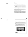
OMRON
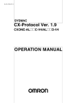
NT2S-SF121B-E
NT2S-SF122B-E
Programmable Terminal
INSTRUCTION SHEET
Thank you for purchasing this OMRON product.
Please read this Instuction sheet and thoroughly familiarize
yourself with functions and characteristics of the product
before use. Please retain this sheet for future.
For more information on specifications and usage, please
refer to each PT & Support Tool.
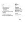
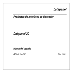
Motor is RUNNING
Speed: 1450 RPM
F1
NEXT
F2
PREV
F3
F4
F5
F6
CLR
OMRON
OMRON Corporation 1998. All Rights Reserved. NT2S-1/0299
12. Always tighten the connector screws after connecting communication
13.
14.
15.
16.
17.
18.
19.
20.
21.
22.
cables.
The max. pull load for cables is 30N. Do not apply loads greater than
this.
Confirm the safety of the system before turning ON or OFF the power
supply.
Start actual application only after sufficiently checking screen data and
the operation of the program in the PC (host).
When using the Programming Console functions, confirm system safety
and then perform the following operations :
• Changing monitor data
• Changing operation modes
• Forced setting or resetting
• Changing preset values or set values.
Do not press the key switch with a force greater than 30N.
Do not accidently press key switches when the backlight is not lit or when
the display does not appear. Confirm the safety of the system before
pressing key switches.
Set memory addresses so that the PT Control Area and PT Notification
Area do not overlap.
When transferring data in screen data units, also transfer data associated
with changes in the memory tables or direct connection.
Do not attempt to disassemble, repair or modify the units in any way.
Do not use benzene, paint thinner or other volatile solvents and do not
use chemically treated cloths.
OMRON
OMRON Corporation
System Components Division
66 Matsumoto
Mishima-city, Shizuoka 411-8511
Japan.
Tel : (81) 559-77-9633 / Fax : (81) 559-77-9097
Regional Headquarters
OMRON EUROPE B.V.
Wegalaan 67-69, NL-2132 JD Hoofddorp
The Netherlands
Tel : (31) 2356-81-300 / Fax : (31) 2356-81-388
OMRON ELECTRONICS, INC.
1 East Commerce Drive, Schaumburg, IL 60173
U.S.A.
Tel : (1) 847-843-7900 / Tel : (1) 847-843-8568
OMRON ASIA PACIFIC PTE. LTD.
83 Clemenceau Avenue,
#11-01, UE Square,
Singapore 239920
Tel : (65) 835-3011 / Tel : (65) 835-2711
Note : Specifications subject to change without notice.
Printed in India.
NOTES
To define the screen specific keys :
You can define the key task, specific for the screen while editing the screen.
You can click on the key to be redefined and configure the task as needed.
How are screens defined?
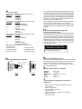
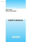
Power Supply
Power Supply for NT2S-SF121B-E : The power supply to the NT2S-SF121B-E
is through the 3 pin terminal of the unit. The connections are as given below.
1
2
3
Screen text can be configured by using the Edit-Screen menu or by clicking
on the Screen tool.
First the software will prompt you to enter the screen number to be edited
or defined. If it is a new screen, then you will be asked to select the type of
screen i.e. normal, special, link screen or function key.
The screen definition dialogue allows you to enter in your screen in a "what
you see is what you get" format. Simply type in your text. To embed any
dynamically animated register variable, press the "Embed Register" button.
It allows you to select the tag as well as format the embedded data. It is
possible to display register values in a bar graph format. Similarly, bit
sensitive text can also be entered by pressing the "Embed bit" button. The
text when bit is ON as well as when the bit is OFF can be entered here.
Pin # 1
Pin # 3
Earth
DC
Pin # 2
D C+
VDC Supply
} 24(1.5W
max)
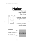
Power Supply for NT2S-SF122B-E : The power supply to the NT2S-SF122B-E
is from the PLC. The figure below shows the connection between the PLC and
the unit through a cable.
PLC PORT
DB9 MALE
CONNECTOR
The screen dialogue allows editing of the screen attributes. Note that a
scrolling screen text can not flash. If chaining is used then the "chained to"
screen must be defined.
DB9 FEMALE
CONNECTOR
To PLC
Programming Port
A list of screen texts called a link screen can be defined. It allows you to pick
a list from the already defined screens and these screens can be viewed by
pressing the NEXT or PREV keys. This mode can be simulated in the software
itself. A standard Drag and Drop format can be used for this definition.
Connecting
Cable
PLC
Note on RTC
23. Do not install the units in any of the following locations :
(This feature is optional for NT2S-SF122B-E).
The RTC values are downloaded in the PLC as follows :
LED Register + 1 (Higher byte)
LED Register + 1 (Lower byte)
LED Register + 2 (Higher byte)
LED Register + 2 (Lower byte)
LED Register + 3 (Higher byte)
LED Register + 3 (Lower byte)
LED Register + 4 (Lower byte)
----------------------
Hours
(HH)
Minutes (MI)
Seconds (SS)
Date
(DD)
Month (MO)
Year
(YY)
Day of week (Sunday=1)
24.
The RTC can be set in the Unit as follows:
During the power-on sequence, press the F1 + F3 keys together.
NT2S-SF121B-E will go in the RTC setting mode. You can set individual
values for the RTC in a menu format. NT2S will show you the current value
for each field and ask you to enter the new value for the field. This can
be done just as any other data entry, using the UP, LEFT, CLR and ENT
keys. You can scroll through this menu list and set all the values for RTC
as needed. These values will be in effect immediately.
You can embed each field in the RTC just like any other register. The
format for embedding is $$.
The tags for each RTC field are predefined in the Tag database, as soon
as a new project is created.
25.
26.
27.
• Locations subject to rapid changes in temperature
• Locations subject to temperatures or humidities outside the
range specified in the specification
• Locations subject to condensation as the result of high
humidity
• Locations subject splashing chemicals or solvents
• Locations subject to oil splashes
• Locations subject to corrosive or flammable gases
• Locations subject to strong shock or vibration
• Locations outdoors subject to direct wind and rain
• Locations subject to strong ultraviolet light
Take appropriate and sufficient countermeasures when installing
systems in the following locations :
• Locations subject to static elctricity or other forms of noise
• Locations subject to strong electromagnetic or magnetic fields
• Locations subject to possible exposure to radioactivity
The whole system may stop depending on how the power supply is
turned ON or OFF. Turn ONor OFF the power supply according to the
specified procedure.
Signals from the key switches may not be input if the switches are
pressed consecutively at high speed. Confirm each input before
proceeding to the next one.
To ensure greater safety for numeric inputs, first check for proper limits
in the PLC.
Pin Connections
Following are the IBM port pin designations for NT2S models :
IBM port pin #
Designation
2
TXD (Transmit)
3
RXD (Receive)
9
Circuit GND
Following are the PLC port pin designations for NT2S-SF121B-E:
PLC port pin #
Designation
2
TX232 (Transmit RS232)
3
RXD (Receive RS232/CMOS)
4&5
Circuit GND
6
VCC (+5V)
7
TXD (Transmit CMOS)
8
PLC Attach
9
Direction Control
Following are the PLC port pin designations for NT2S-SF122B-E:
PLC port pin #
Designation
2
Direction Control
3
TX232 (Transmit RS232)
4
VCC (+5V)
5
Circuit GND
6
TXD (Transmit CMOS)
7, 8
RXD (Receive RS232/CMOS)
Standard cables that are available to connect to Omron PLC
peripheral port are :
For NT2S-SF121B-E:
For NT2S-SF122B-E:
NT2S-CN212 ( 2 meter )
NT2S-CN222 ( 2 meter )
NT2S-CN215 ( 5 meter )
NT2S-CN225 ( 5 meter )
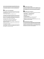
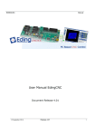
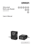
Panel
Screw to hold clamp
and unit on Panel
To define the global task for the keys :
The NT2S-SF121B-E/NT2S-SF122B-E has 6 keys that can be assigned
user definable functions by using the pull down menu of Edit-Function
keys or by clicking on the NT2S-SF121B-E/NT2S-SF122B-E key tool on
the tool station. The dialogue shows the function keys along with the user
assignable legends. Click on the key you wish to define, select the tag
on which the key operates on and the action. Depending on what type
of tag ( bit or register ) is selected, only actions that can be performed
on that tag will be enabled.
DO NOT USE THE FUNCTION BUTTONS
FOR EMERGENCY STOP APPLICATIONS!
It is advised that separate switches be used outside
the PLC for ANY emergency stops.
The project can be downloaded to the NT2S-SF121B-E/NT2S-SF122B-E
by selecting the Communicate-Download to Unit menu or by clicking the
link between the PC and NT2S-SF121B-E/NT2S-SF121B-E on the
toolstation. Connect the PC to the unit for downloading on the serial
port. Use a simple DB9 cable.
System requirements for NT2 ST
Mounting Clamp
Gasket
Fig. A
How are function keys configured?
How to download to the unit?
How is the unit panel mounted?
Panel
For any project, you must define the Tag database first. Tag is a register
or coil which is used in your application. Tags can be defined by using
either Edit-Tag database menu or Tag tool. A tagname can be assigned
to each tag and the tag can be referred to by it's name subsequently,
making it very convenient to use. Tag database can be accessed from
anywhere in the software. It is advised to define all the registers/coils you
will be using in your project ahead of time.
Once the Tag database is defined, assign the STR and the LED register.
This can be done using Edit-Setup menu or by clicking on the
PLC-NT2S-SF121B-E/NT2S-SF122B-E link on the Toolstation. Use a
bit addressable register as the LED register so that each LED can be easily
controlled.
Fig. B
•
•
•
•
•
Processor
Windows
Screen Display
Mouse
Memory
:
:
:
:
:
386 or higher.
3.1 or higher.
VGA or better, Color monitor.
Optional.
2 MB or more.
The following programming sequence is
suggested
•
•
•
•
•
•
•
Start a new project. Select NT2S-SF121B-E/NT2S-SF122B-E
and PLC model.
Create the Tag database.
Set the STR and the LED register.
Program in screens.
Define the function keys, if applicable to your application.
Save your work to disk.
Download work to Unit.
Another method is to use a special screen which allows data entry. Here,
the format in which data is edited is user definable. When this special
screen is triggered, the operator can enter the new data using the arrow
keys and the CLR and ENT keys. Coils can also be edited this way.
How is the unit configured?
Each unit MUST be configured using the Windows based setup software
provided with the unit. The software is quite easy to use and contains
comprehensive online help.
Invoke the NT2 ST software that is installed on your PC.
The software can be used either from the pull down menus or by using
the comprehensive Toolstation that appears on the bottom half of the
Window. Each tool has balloon help associated with it to help identify
the function. If the Toolstation does not appear on your screen, it can
be turned on using the "Options" pull down menu.
Select NEW project by clicking on the corresponding tool.
A window will appear showing all the available products.
Select the NT2S-SF121B-E/NT2S-SF122B-E. The bitmap of the unit
will appear on the screen.
Select your PLC from the list of available drivers. Also select the correct
PLC model that you are using.
The Toolstation now will allow you to configure the NT2S-SF121B-E/
NT2S-SF122B-E. If any error screen indicating that "PLC driver is not
found" appears, contact factory for support.
What does the unit do?
The NT2S-SF121B-E/NT2S-SF122B-E connects to YOUR PLC over it's
programming or standard communications port. It is capable of displaying
screens based on conditions in the PLC and is capable of changing data in
the PLC registers/coils. It can also print screen text over the serial port.
What does the unit have?
The NT2S-SF121B-E/NT2S-SF122B-E has the following functional blocks:
• NT2S-SF121B-E - 10-30 VDC power supply
• NT2S-SF122B-E - Supply from the PLC
• 2 lines of 16 character backlit LCD
• 6 keys keypad
• 2 LEDs for annunciation
• 8K / 32K EEPROM memory for PLC driver and screens
• RS232C Port to connect the PLC for programming
• RS232C Port to connect the PC for programming and also for printing
• RTC (Optional for NT2S-SF122B-E)
How does the unit work?
The NT2S-SF121B-E/NT2S-SF122B-E must be configured for YOUR application. It stores the configuration details and screens in it's memory. Based
on conditions in the PLC the configured screens are displayed. When a key
is pressed, the configured action is taken. The unit continuously communicates with the PLC to detect conditions for displaying screens, to control
the 2 LEDs on the unit and for it's internal operations.
How are screens displayed?
What do the keys do?
Each screen has a unique number. The NT2S-SF121B-E/NT2SSF122B-E scans a user definable register called as Screen Triggering
Register (STR) in the PLC. To display screen number "XXX", simply
put the number "XXX" in this STR. Valid screen numbers are 1 to 65528.
The keys on the NT2S-SF121B-E/NT2S-SF122B-E can perform user defined
functions. The same keys can be used to change data or to scroll through
a list of screens. The operation of keys depends on the type of screen being
displayed as follows:
Type of screen
Key operations
Normal
All keys perform user defined functions
as configured by the software
Special
Arrow keys, CLR and ENT keys are used
(with data entry)
to change data. NEXT and PREV keys
act as function keys.
Link
NEXT and PREV keys are used to scroll
through the list of screens. Other keys
act as function keys.
For all both line screens, the keys can be redefined to perform user defined
task which can be different from global key task.
Normal screen are used to monitor status or alarms. A screen can have
register values or bit controlled text embedded in it which is dynamically
updated. RTC related data can also be embedded.
Special screen are used to change data in the PLC or to turn a coil ON
or OFF.
Link screen defines a list of screens that can be viewed consecutively
by pressing the NEXT or PREV keys.
What are screen attributes?
A normal screen can flash or scroll on the display. Any screen can be
assigned to be sent to a serial printer. A screen can be assigned to the
top line, bottom line or both lines. A minimum time can be assigned
to ensure that the operator has enough time to view the screen. If the
PLC calls other screen in this time, they will be stored on a queue inside
the unit. The maximum queue size is 3 screens.
Note: The queue can be cleared by putting the number 65535 in STR.
You can likewise call a screen on priority by putting the number 65535
in STR first and then calling the desired screen number.
How are LEDs controlled?
The NT2S-SF121B-E/NT2S-SF122B-E scans a user definable register called
the LED register. The least significant 2 bits in this register are mapped to
the LEDs. If a bit is ON, the corresponding LED is turned ON.
How can data be entered?
There are two ways to edit data using the NT2S-SF121B-E/NT2S-SF122B-E.
One way is to use function keys. The function keys can download a constant
or can increment / decrement assigned register value or can change a coil
status.
NOTES
Notice :
1. When unpacking the units, check carefully for any external scratches
2.
3.
4.
5.
6.
7.
8.
9.
10.
or other damage. Also, shake the units gently and check for any
abnormal sound.
Turn OFF the power supply to the PT before mounting or dismounting
I/F Units. Correctly mount the I/F Units according to the User’s Manual
of the PT.
Do not touch the PCBs with bare hands. Discharge static electricity
accumulated in your body in advance.
Tighten the mounting brackets evenly. Make sure the panel is not
dirty or warped and that it is strong enough to hold the units.
Do not let metal particles enter the units when preparing the panel.
Double check all the connections before turning ON the power supply.
Do not perform a dielectric voltage test.
Make sure that the connector screws are properly tightened.
Always tighten the connector screws after connecting communication
cables.
The max. pull load for cables is 30N. Do not apply loads greater than
this.
NOTES
OMRON
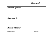
NT2S-SF123B-E
Programmable Terminal
INSTRUCTION SHEET
Thank you for purchasing this OMRON product.
Please read this Instuction sheet and thoroughly familiarize
yourself with functions and characteristics of the product
before use. Please retain this sheet for future.
For more information on specifications and usage, please
refer to each PT.
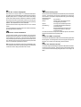
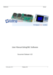
Motor is RUNNING
Speed: 1450 RPM
F1
REG
F2
DATA
F3
F4
F5
F6
CLR
OMRON
OMRON Corporation 1998. All Rights Reserved. NT2S-2/0299
11. Confirm the safety of the system before turning ON or OFF the supply
to the unit.
12. Start actual application only after sufficiently checking screen data and
the operation of the program in the PLC.
13. When using the Programming Console functions, confirm system safety
and then perform the following operations :
• Changing monitor data
• Changing operation modes
• Forced setting or resetting
• Changing preset values or set values.
14. Do not press the key switch with a force greater than 30N.
15. Do not accidently press key switches when the backlight is not lit or when
the display does not appear. Confirm the safety of the system before
pressing key switches.
16. Do not attempt to disassemble, repair or modify the units in any way.
17. Do not use benzene, paint thinner or other volatile solvents and do not
use chemically treated cloths.
18. Signals from the key switches may not be input if the switches are
pressed consecutively at high speed. Confirm each input before
proceeding to the next one.
19. To ensure greater safety for numeric inputs, first check for proper limits
in the PLC.
NOTES
Triggering screens
Pin Connections
As can be seen from the above examples, there are two ways to display
screens with the NT2S-SF123B-E :
Following are the PLC port pin designations for NT2S-SF123B-E:
PLC port pin #
Designation
1.
2, 3, 5
4
6
7
1, 8, 9
Keep all the message characters in the data memory ( the Omron
PLCs have lot of data registers which in most applications involving
simple digital controls are not used anyway ) and simply change the
offset register to display different screens.
The user can fill the data memory using the “data display editor” menu of
the PLC programming software.
2.
Note that the data memory as well as the program memory can be
used for embedding of data.
Of course, a combination of the two methods can be used to
optimize the memory usage.
OMRON
OMRON Corporation
System Components Division
66 Matsumoto
Mishima-city, Shizuoka 411-8511
Japan.
Tel : (81) 559-77-9633 / Fax : (81) 559-77-9097
Regional Headquarters
OMRON EUROPE B.V.
Wegalaan 67-69, NL-2132 JD Hoofddorp
The Netherlands
Tel : (31) 2356-81-300 / Fax : (31) 2356-81-388
OMRON ELECTRONICS, INC.
1 East Commerce Drive, Schaumburg, IL 60173
U.S.A.
Tel : (1) 847-843-7900 / Tel : (1) 847-843-8568
OMRON ASIA PACIFIC PTE. LTD.
83 Clemenceau Avenue,
#11-01, UE Square,
Singapore 239920
Tel : (65) 835-3011 / Tel : (65) 835-2711
Note : Specifications subject to change without notice.
Printed in India.
GND
VCC (+5V)
TXD (Transmit CMOS)
RXD (Receive CMOS)
NC
Standard cable that is available to connect to Omron PLC peripheral
port is : NT2S-CN222 ( 2 meter )
20. Do not install the units in any of the following locations :
• Locations subject to rapid changes in temperature
• Locations subject to temperatures or humidities outside the
range specified in the specification
• Locations subject to condensation as the result of high
humidity
• Locations subject splashing chemicals or solvents
• Locations subject to oil splashes
• Locations subject to corrosive or flammable gases
• Locations subject to strong shock or vibration
• Locations outdoors subject to direct wind and rain
• Locations subject to strong ultraviolet light
21. Take appropriate and sufficient countermeasures when installing
systems in the following locations :
• Locations subject to static elctricity or other forms of noise
• Locations subject to strong electromagnetic or magnetic fields
• Locations subject to possible exposure to radioactivity
22. The whole system may stop, depending on how the power supply is
turned ON or OFF. Turn ONor OFF the power supply according to the
specified procedure.
General:
The NT2S-S123B-E is intended to be used as a low cost Operator
interface for PLCs which are rich in program memory or data memory
areas such as the Omron C Series PLCs.
The NT2S-S123B-E has the following features:
Feature
NT2S-SF123B-E
Display
Backlit 2X16 LCD
LEDs
2
Keys
6
ASCII screens
32 characters
Embedded variables
16
Each key is mapped from work bits 201.00 to 201.05. Every time a key is
pressed, the corresponding bit as shown in the table below is held on while
the key is pressed. The keys also have alternate functions.
Work Bit Register mode function
F1/REG
F2/DATA
F3/DOWN
201.00
201.01
201.02
F4/UP
201.03
F5/CLR
201.04
F6/ENT
201.05
h.
Move “s “ into DM0215. This command completes the screen by
appending the “s ” to bake time.
This will put the following data in the data words below:
("b" is used for a space, i.e. 20H)
Key definitions:
Key
g.
Put 03032E03H in words DM0213 and DM0214. The NT2S-SF123B-E
will read data in DM0003 and embed in xx.x format.
Word
DM0200
DM0201
DM0202
DM0203
DM0204
DM0205
DM0206
DM0207
ASCII
Do
or
:b
CL
OS
ED
bb
bb
Hex
#446F
#6F72
#3A20
#434C
#4F53
#4544
#2020
#2020
Word
DM0208
DM0209
DM0210
DM0211
DM0212
DM0213
DM0214
DM0215
ASCII
BA
KE
TI
ME
:b
sb
Hex
#4241
#4B45
#5449
#4D45
#3A20
#0303
#2E03
#7320
Changes register prefix
Enters data entry mode
Increments register number or data
depending on mode
Decrements register number or data
depending on mode
Clears data field to 0 / Register field to
first register value
Accepts new data and sends to the PLC
How is the unit panel mounted?
Register mode:
Panel
Panel
Screw to hold clamp
and unit on Panel
In the register mode, the operator can access all the registers and bits
in the PLC.
By pressing the REG key, the operator can scroll through the register
prefixes. By using the UP / DOWN keys, the register numbers can be
accessed. Data can be changed in the registers by pressing the DATA
key. The data field will blink to indicate that the unit is ready to accept
new data. At this time, the UP / DOWN keys can be used to edit data
followed by the ENT key.
Mounting Clamp
Gasket
Fig. A
Fig. B
Power Supply
It is advisable to create a “password” screen which can block the usage
of the register mode.
The power supply to the NT2S-SF123B-E is from the PLC. The figure below
shows the connection between the PLC and the unit through a cable.
Bar Graph:
PLC PORT
DB9 MALE
CONNECTOR
DB9 FEMALE
CONNECTOR
To PLC
Programming Port
Connecting
Cable
PLC
NT2S-SF123B-E uses DM0012 to DM0015 registers to hold bar graph
values to be displayed. If Offset register points to DM0200 then put
Hex value 0C0C into DM0200 onwards to display bar graph with the
value in DM0012.
Example:
Put 0C0C into DM0200, DM0201, DM0202, DM0203 and 200 into
DM0020. This will display bar graph 8 characters wide. Maximum
length is 16 characters. Each character on display can display five
vertical lines. To display full bar graph put # 80 into DM0012 and
0C0C from DM0200 to DM0207.
To display Bar Graph with value in DM0013, put 0D0D in DM0200
onwards.
Example 2: Embed a variable in the screen
Unit Operations:
Suppose the following screen needs to be displayed on the
NT2S-SF123B-E :
The work bits 200.00 to 200.15 control the mode of operation of the unit.
Door: CLOSED
BAKETIME: 13.6s
Suppose the bake time is available in data word DM0100 and the oven
status is given by bit 001.00.
To display this screen, do the following:
a.
Move number 200 in DM0020 since the screen will be stored in DM0200
onwards.
b.
Move character string “Door:” into 2 words, i.e. DM0200 and DM0201.
c.
Move characters “OPEN” if bit 001.00 is ON or characters “CLOSED” if
001.00 is OFF.
This is a way to implement bit sensitive screens.
e.
In a similar manner, embed the characters “BAKETIME: ” into 5 words
from DM0208.
f.
NT2S-SF123B-E uses DM0000 to DM0011 registers for embedding data.
Here we select DM0003 to be used for embedding. So, move the data of
DM0100 into DM0003 so that embedding can be done.
Work Bit
200.00
200.01
200.02 & 200.03
200.04 to 200.07
200.08 & 200.09
200.10 & 200.11
200.12 to 200.14
200.15
Function
Controls LED0
Controls LED1
Not used
Reserved for future use
00: Screen mode
01: Register mode
10: Operator mode 11: Invalid
Timeout to screen mode from Operator mode
00: 10 seconds
01: 20 seconds
10: 30 seconds
11: 40 seconds
Reserved for future use
To disable data entry in Screen mode
(ON : Disable)
From the above table, it is clear that the unit will display ASCII text (see section
on Screens for more details on this ) if 200.08 and 200.09 are OFF. To allow
operators to view and edit the registers, 200.08 is to be kept ON. If 200.08 is OFF,
the unit will not display any registers and the function keys will only act as push
buttons mapped to the corresponding bits from 201.00. Refer to “Register Mode”
for details. If 200.09 is ON, REG key press will allow an operator to view the registers.
The REG key will scroll through the available register types whereas the UP and
DOWN arrow keys will scroll through the register/bit numbers. After timeout
specified by bits 10 and 11 and if no key is pressed, the unit will switch back to
the Screen mode and display screens. Thus Operator mode is a combination
of Register as well as Screen modes.
Screens
Example 1: Display a static screen
The unit displays 32 characters from the PLC memory. These characters
are taken from the PLC data registers.
The unit tracks register DM0020 ( the Offset register ) in the PLC. The number
in DM0020 gives the start address of the data register block which contains the
characters to be displayed. For example, if DM0020 has number 124 in it, the
unit will read 16 registers from DM0124, i.e. from DM0124 to DM0139 and display
the corresponding characters.
Each register contains two bytes. Each ASCII character to be displayed is
one byte. So, each word contains two characters that can be displayed. All the
PLC ladder logic has to do is to put the correct words in the registers being read
by the unit so that a proper screen can be displayed.
As mentioned above, the starting address of the screen data block is
controlled by the Offset register, i.e DM0020. Hence, there can be two methods
of changing the screen to be displayed. One is to keep the value in DM0020
constant and change the data in the screen registers by the ladder logic. Second
is to keep the screen text in the data memory (by editing DM registers) and change
the value in DM0020 so as to point to the correct memory address to display the
desired screen.
It is possible to embed registers in the screens. The unit reads 16 registers
from DM0000 to DM0015 (in which DM0012 to DM0015 are used for Bar Graph)
in every scan. The data in these registers can be embedded in the screens. To
do so, use hex bytes 0 to B (C to F used for Bar Graph) corresponding to register
DM0000 to DM0011 respectively in the screen. Refer to the example given which
explains the embedding of registers. It is possible to embed one data entry field
in screens. It is similar to embedding register, only instead of 0 to F use 10 to 1F
hex bytes to address DM0000 to DM0015. The registers DM0000 to DM0015 can
be edited with this feature one at a time in a screen.
Suppose the following screen needs to be displayed on the
NT2S-SF123B-E :
Last Rinse Cycle
Water pump is on
To display this screen, do the following:
a.
Move number 200 in DM0020 since the screen text will be stored
in DM0200 onwards.
b.
Move character string “Last Rinse Cycle” into 8 words from DM0200.
c.
In a similar manner, the characters “Water pump is on” can be embeded
into 8 words from DM0208. (i.e. from DM0208 to DM0215).
This will put the following data in data words below: ("b" is used for a space)
Word
DM0200
DM0201
DM0202
DM0203
DM0204
DM0205
DM0206
DM0207
ASCII
La
st
bR
in
se
bC
yc
le
Hex
#4C61
#7374
#2052
#696E
#7365
#2043
#7963
#6C65
Word
DM0208
DM0209
DM0210
DM0211
DM0212
DM0213
DM0214
DM0215
ASCII
Wa
te
rb
pu
mp
bi
sb
on
Hex
#5761
#7465
#7220
#7075
#6D70
#2069
#7320
#6F6E