1
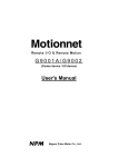
User's Manual
For
PCL6113/6123/6143
Pulse Control LSI
Nippon Pulse Motor Co., Ltd.
[Preface]
Thank you for considering our pulse control LSI, the "PCL6100 series."
Before using the product, read this manual to become familiar with the product.
Please note that the section "Handling Precautions" which include details about installing this IC, can
be found at the end of this manual.
[Cautions]
(1) Copying all or any part of this manual without written approval is prohibited by copyright laws.
(2) The specifications of this LSI may be changed to improve performance or quality without prior
notice.
(3) Although this manual was produced with the utmost care, if you find any points that are unclear,
wrong, or have inadequate descriptions, please let us know.
(4) We are not responsible for any results that occur from using this LSI, regardless of item (3) above.
- Explanation of the description in this manual
1. "X" "y" "z" and "u" at the foot of terminal names and bit names refer to X axis, Y axis, Z axis and U axis,
respectively.
____
2. Terminals with an overline above the name (ex. RST ) use negative logic. Their logic cannot be changed.
Terminals without an overline are positive logic, or their output logic can be changed.
3. When describing the bits in registers, "n" refers to a bit position. "0" refers to a bit position and it is prohibited
to write to any other than "0" and this bit always returns "0" when read.
4. Unless otherwise indicated, figures related to timing (intervals) in this manual are based on a reference clock
of 19.6608 MHz.
INDEX
1. Outline and Features ........................................................................................................................................1
1-1. Outline .......................................................................................................................................................1
1-2. Features ....................................................................................................................................................1
2. Specification .....................................................................................................................................................4
3. Terminal Assignment Diagram .........................................................................................................................5
3-1. PCL6113 ...................................................................................................................................................5
3-2. PCL6123 ...................................................................................................................................................5
3-3. PCL6143 ...................................................................................................................................................6
4. Functions of Terminals .....................................................................................................................................7
5. Block Diagram ................................................................................................................................................13
6. CPU-I/F ...........................................................................................................................................................13
6-1. Setting the CPU interface type ................................................................................................................14
6-2. Hardware design precautions .................................................................................................................14
6-3. Examples of CPU-I/F ..............................................................................................................................15
6-4. Address map ...........................................................................................................................................17
6-4-1. Axis arrangement map ....................................................................................................................17
6-4-2. Internal map of each axis ................................................................................................................17
6-5. Description of the map details .................................................................................................................19
6-5-1. Write the command code and axis selection (COMB0, COMB1)....................................................19
6-5-2. Write to an output port (OTPW, OTPB) ...........................................................................................20
6-5-3. Write/read the input/output buffer (BUFW, BUFB) ..........................................................................20
6-5-4. Reading the main status (MSTSW, MSTSB) ..................................................................................21
6-5-5. Reading the sub status and input/output port (SSTSW, SSTSB, IOPB) .........................................23
7. Commands (Operation and Control Commands) ...........................................................................................24
7-1. Operation commands ..............................................................................................................................24
7-1-1. Procedure for writing an operation command (the axis assignment is omitted) .............................24
7-1-2. Start command ................................................................................................................................25
7-1-3. Speed change command.................................................................................................................25
7-1-4. Stop command ................................................................................................................................26
7-1-5. NOP (do nothing) command ............................................................................................................26
7-2. General-purpose output bit control commands .......................................................................................27
7-3. Control command ....................................................................................................................................28
7-3-1. Software reset command.................................................................................................................28
7-3-2. Counter reset command ..................................................................................................................28
7-3-3. ERC output control command .........................................................................................................28
7-3-4. Pre-register control command .........................................................................................................28
7-3-5. PCS input command........................................................................................................................28
7-3-6. LTCH input (counter latch) command .............................................................................................28
7-4. Register control command ......................................................................................................................29
7-4-1. Procedure for writing data to a register (the axis assignment is omitted) .......................................29
7-4-2. Procedure for reading data from a register (the axis assignment is omitted) .................................29
7-4-3. Table of register control commands ................................................................................................30
7-5. General-purpose output port control command ......................................................................................31
7-5-1. Command writing procedures .........................................................................................................31
7-5-2. Command bit allocation ...................................................................................................................31
8. Registers .........................................................................................................................................................32
8-1. Table of registers ....................................................................................................................................32
8-2. Pre-register .............................................................................................................................................33
8-3. Description of the registers ....................................................................................................................35
8-3-1. PRMV (RMV) register ......................................................................................................................35
8-3-2. PRFL (RFL) register ........................................................................................................................35
8-3-3. PRFH (RFH) register .......................................................................................................................35
8-3-4. PRUR (RUR) register ......................................................................................................................35
8-3-5. PRDR (RDR) register ......................................................................................................................36
8-3-6. PRMG (RMG) register .....................................................................................................................36
8-3-7. PRDP (RDP) register.......................................................................................................................36
8-3-8. PRMD (RMD) register .....................................................................................................................37
8-3-9. PRIP (RIP) register ..........................................................................................................................38
8-3-10. PRUS (RUS) register.....................................................................................................................38
8-3-11. PRDS (RDS) register.....................................................................................................................39
8-3-12. RENV1 register ..............................................................................................................................39
8-3-13. RENV2 register ..............................................................................................................................41
8-3-14. RENV3 register ..............................................................................................................................43
8-3-15. RCUN1 register .............................................................................................................................44
8-3-16. RCUN2 register .............................................................................................................................44
8-3-17. RCMP1 register .............................................................................................................................44
8-3-18. RCMP2 register .............................................................................................................................44
8-3-19. RIRQ register .................................................................................................................................45
8-3-20. RLTC1 register ..............................................................................................................................45
8-3-21. RLTC2 register ..............................................................................................................................45
8-3-22. RSTS register ................................................................................................................................46
8-3-23. REST register ................................................................................................................................47
8-3-24. RIST register .................................................................................................................................47
8-3-25. RPLS register ................................................................................................................................48
8-3-26. RSPD register ................................................................................................................................48
8-3-27. RSDC register ...............................................................................................................................48
9. Operation Mode ..............................................................................................................................................49
9-1. Continuous operation mode using command control .............................................................................49
9-2. Positioning operation mode.....................................................................................................................49
9-2-1. Positioning operation (MOD: 41h) ...................................................................................................49
9-2-2. Timer operation (MOD: 47h) ...........................................................................................................49
9-3. Pulsar (PA/PB) input mode .....................................................................................................................50
9-3-1. Continuous operation using a pulsar input (MOD: 01h) ..................................................................52
9-3-2. Positioning operations using a pulsar input (MOD: 51h) .................................................................52
9-4. External switch operation mode ..............................................................................................................53
9-4-1. Continuous operation using an external switch (MOD: 02h) ...........................................................53
9-4-2. Positioning operation using an external switch (MOD: 56h) ...........................................................54
9-5. Origin return operation mode ..................................................................................................................55
9-5-1. Origin return operation 0 (ORM = 0) ...............................................................................................57
9-5-2. Origin return operation 1 (ORM=1)..................................................................................................58
9-6. Linear interpolation operation .................................................................................................................59
9-6-1. Outline of interpolation operation ....................................................................................................59
9-6-2. Interpolation procedures ..................................................................................................................59
9-6-3. Operation during interpolation .........................................................................................................61
10. Speed patterns .............................................................................................................................................62
10-1. Speed patterns ......................................................................................................................................62
10-2. Speed pattern settings ..........................................................................................................................63
10-3. Manual FH correction ............................................................................................................................67
10-4. Example of setting up an acceleration/deceleration speed pattern ......................................................71
10-5. Changing speed patterns while in operation .........................................................................................72
11. Description of the Functions .........................................................................................................................73
11-1. Reset .....................................................................................................................................................73
11-2. Target position override ........................................................................................................................74
11-2-1. Target position override 1 ..................................................................................................................74
11-2-2. Target position override 2 (PCS signal) ........................................................................................75
11-3. Output pulse control ..............................................................................................................................76
11-3-1. Output pulse mode ........................................................................................................................76
11-3-2. Output pulse length and operation complete timing ......................................................................77
11-4. Mechanical external input control .........................................................................................................78
11-4-1. +EL, -EL signal ..............................................................................................................................78
11-4-2. SD signal .......................................................................................................................................79
11-4-3. ORG, EZ signals ............................................................................................................................81
11-5. Servomotor I/F ......................................................................................................................................82
11-5-1. INP signal ......................................................................................................................................82
11-5-2. ERC signal .....................................................................................................................................83
11-5-3. ALM signals ...................................................................................................................................84
11-6. External start, simultaneous start ..........................................................................................................85
11-6-1. CSTA signal ...................................................................................................................................85
11-6-2. PCS signal .....................................................................................................................................86
11-7. External stop / simultaneous stop .........................................................................................................87
11-8. Emergency stop ....................................................................................................................................88
11-9. Counter .................................................................................................................................................89
11-9-1. Counter type and input method .....................................................................................................89
11-9-2. Counter reset .................................................................................................................................91
11-9-3. Stop the counter ............................................................................................................................92
11-10. Comparator .........................................................................................................................................93
11-10-1. Comparator types and functions .................................................................................................93
11-10-2. Ring count function ......................................................................................................................94
11-11. Synchronous starting ..........................................................................................................................95
11-11-1. Start triggered by another axis stopping......................................................................................95
11-11-2. Start on an internal synchronous signal ......................................................................................96
11-12. Output an interrupt signal ....................................................................................................................98
12. Electrical Characteristics ............................................................................................................................100
12-1. Absolute maximum ratings ..................................................................................................................100
12-2. Recommended operating conditions ..................................................................................................100
12-3. DC characteristics ...............................................................................................................................100
12-4. AC characteristics 1) (reference clock) ...............................................................................................101
12-5. AC characteristics 2) (CPU I/F) ...........................................................................................................102
12-5-1. 16-bits I/F-1) (IF1 = L, IF0 = L) 68000, etc ..................................................................................102
12-5-2. 16-bits I/F-2 (IF1=L, IF0=H) H8 ...................................................................................................103
12-5-3. 16-bits I/F-3 (IF1=H, IF0=L) 8086 etc. .........................................................................................104
12-5-4. 8-bits I/F-2 (IF1=H, IF0=H) Z80 etc. ............................................................................................105
12-6. Operation timing (common for all axes) ..............................................................................................106
13. External Dimensions ...................................................................................................................................110
13-1. PCL6113 .............................................................................................................................................110
13-2. PCL6123 .............................................................................................................................................111
13-3. PCL6143 .............................................................................................................................................112
14. Command list ..............................................................................................................................................113
14-1. Operation commands ..........................................................................................................................113
14-2. General-purpose port control commands ...........................................................................................113
14-3. Control commands ..............................................................................................................................113
14-4. Register control commands ................................................................................................................114
15. Handling Precautions..................................................................................................................................115
15-1. Design precautions .............................................................................................................................115
15-2. Precautions for transporting and storing LSIs .....................................................................................115
15-3. Precautions for installation ..................................................................................................................115
15-4. Other precautions ................................................................................................................................116
1. Outline and Features
1-1. Outline
The PCL6113, PCL6123, PCL6143 are CMOS LSIs designed to provide the oscillating, high-speed pulses
needed to drive stepper motors and servomotors (pulse string input types) by various commands from
CPU-I/F.
It can offer various types of control over the pulse strings and therefore the motor performance. These include
continuous operation, positioning, origin return at a constant speed, linear acceleration/deceleration, and
S-curve acceleration/deceleration.
The number of control axes is as follows: one for the PCL6113, two for the PCL6123, and four for the
PCL6143. They offer linear interpolation of multiple axes (using single or multiple LSIs), confirmation of a
LSI's operation status, and interrupt output by a variety of conditions. In addition, they are equipped with
servomotor driver control features.
These functions can be used with simple commands. The intelligent design philosophy reduces the burden on
the CPU units to control motors.
1-2. Features
Single voltage power supply 3.3 V
These LSIs can be operated by single voltage power supply from 3.0 V to 3.6 V.
The output signal level range is 0 to 3.3 V. The input signal level range is 0 to 3.3 V, or 0 to 5 V.
Super high-speed pulse train output
Up to 9.8 Mpps can be output when using a 19.6608 MHz (standard) reference clock, or up to 15 Mpps
when using a 30 MHz (maximum) reference clock.
CPU-I/F
These LSIs all contain integral interface circuits for four different CPU-I/F types, and they can be connected
to a wide variety of CPUs.
Examples of CPU types: Z80, 8086, H8, or 68000 etc.
Acceleration/deceleration speed control
Linear acceleration/deceleration and S-curve acceleration/deceleration are available.
Linear acceleration/deceleration can be inserted in the middle of an S-curve acceleration/deceleration
curve by setting S-curve range.
The S-curve range can specify each acceleration and deceleration characteristics independently. Therefore,
you can create an acceleration/deceleration profile that consists of linear acceleration and S-curve
deceleration, or vice versa.
Interpolation
These LSIs can perform linear interpolation (offering synchronized operation) of any number of axes.
Operation speed override
In single axis operation, speed can be changed during operation in any of the operation modes.
However, the speed cannot be changed during linear interpolation.
Target position override 1) and 2)
1) The target position (feeding amount) can be changed while feeding in the positioning mode.
If the current position exceeds the newly entered position, the motor will decelerate and stop
(immediately stop when already feeding at a constant speed), and then feed in the reverse direction.
2) Operation starts in the same as the continuous mode. When an external signal is received, the LSI
outputs specified number of pulses and the motor will stop.
Triangle drive elimination (FH correction function)
In the positioning mode, when a small number of pulses are output, this function automatically lowers the
maximum speed (FH) and eliminates triangle driving.
Pre-register function
-1-
Next set of data (feeding amount, initial speed, feeding speed, acceleration rate, deceleration rate, speed
magnification rate, ramping-down point, operation mode, S-curve range on an acceleration, S-curve range
on a deceleration) can be written while executing current data.
When the current operation is complete, the system will immediately execute the next operation.
Counter circuits
The following two counters are available separately for each axis.
Counter
Purpose of use
Count Input
COUNTER 1
28-bit counter for position control
Output pulses, EA/EB signal input
COUNTER 2
28-bit counter for position control
Output pulses, EA/EB signal input
Both of them can also latch values by writing a command, or by providing an LTC, or ORG signal.
The LSIs can also be set to reset automatically soon after writing a command and latching these signals.
Comparators
There are 2 comparator circuits for each axis. They can be used to compare target values and internal
counter values.
Comparator 1 can be compared with COUNTER 1 and Comparator 2 can be compared with COUNTER 2.
Simultaneous start function
Multiple axes controlled by this LSI, or controlled by multiple sets of this LSI, can be started to move at the
same time by a command or by an external signal.
Simultaneous stop function
Multiple axes controlled by this LSI, or controlled by multiple sets of this LSI, can be stopped at the same
time by a command, by an external signal, or by an error stop on any axis.
Manual pulsar input function
By applying manual pulse signals, you can rotate a motor directly.
The input signals can be 90 degree phase difference signals (1x, 2x, or 4x) or up and down signals.
When an EL signal of a feed direction is input, the LSI stops outputting pulses. But, it can feed in the
opposite direction without any command.
Direct input of external operation switch
An input terminal for operation switch is provided to directly drive a motor with an external operation switch.
These switches turn the motor forward (+) and backward (-).
The results of a switch press can be set to keep feeding pulses while pressed down, or to feed a specified
number of pulses for each press of the switch.
Operation mode
The basic operations of this LSI are: continuous operation, positioning, origin return, and linear interpolation.
By setting optional operation mode bits, you can use a variety of operations.
<Examples of the operation modes>
1) Start/stop by command.
2) Continuous operation and positioning operation using a manual pulsar.
3) Continuous operation and positioning operation using an external switch.
4) Origin return operation.
5) Positioning operation using commands.
_____
6) Hardware start of the positioning operation using CSTA input.
7) Feed for a specified amount after turning ON the PCS. (Target position override (2))
Origin return sequences
<Examples of origin return sequences>
1) Feeds at constant speed and stops when the ORG signal is turned ON
2) Feeds at constant speed and stops when the LSI finishes counting specified number of EZ pulses (after
the ORG signal is turned ON).
3) Feeds at high speed, decelerates when the SD signal is turned ON, and stops when the ORG signal is
turned ON.
4) Feeds at high speed, decelerates, and stops when the ORG signal is turned ON.
5) Feeds at high speed, starts deceleration when the ORG signal is turned ON. Then, stops when the LSI
-2-
finishes counting specified number of EZ pulses.
Mechanical input signals
The following four signals can be input for each axis.
1) +EL: When this signal is turned ON, while feeding in the positive (+) direction, the motor stops
immediately (with deceleration). When this signal is ON, no further movement occurs in the
positive (+) direction. (The motor can be rotated in the negative (-) direction.)
2) -EL: Functions the same as the +EL signal except that it works in the negative (-) direction.
3) SD: This signal can be used as a deceleration signal or a deceleration stop signal, according to the
software setting. When this is used as a deceleration signal, and when this signal is turned ON
during a high speed feed operation, the motor will decelerate to the FL speed. If this signal is
ON and the motor is started, the motor will run at the FL constant speed. When this signal is
used as a deceleration stop signal, and when this signal is turned ON during a high speed feed
operation, the motor will decelerate to the FL speed and then stop.
4) ORG: Input signal for an origin return operation.
For safety, make sure the +EL and -EL signals stay on from the EL position until the end of each stroke.
The input logic for these signals can be changed using the ELL terminal.
The input logic of the SD and ORG signals can be changed using software.
Servomotor I/F
The following three signals can be used as an interface for each axis.
1) INP: Input positioning complete signal that is output by a servomotor driver.
2) ERC: Output deviation counter clear signal to a servomotor driver.
3) ALM: Regardless of the direction of operation, when this signal is ON, the motor stops immediately
(decelerate and stop). When this signal is ON, no movement can occur on this axis.
While the LSI is operating in the timer mode, it cannot be stopped using the ALM input.
Even though the motor is stopped, the LSI will output an INT (interrupt request) when an ALM
signal is received.
The input logic of the INP, ERC, and ALM signals can be changed using software.
The ERC signal is a pulsed output. The pulse length can be set. (12 us to 104 ms. A level output is also
available.)
Output pulse specification
Output pulses can be set to a common pulse, 2-pulse mode or 90-degree phase difference mode. The
output logic can also be selected.
_____
Emergency stop signal ( CEMG) input
When this signal is turned ON, movement on all axes stops immediately. While this signal is ON, no
movement is allowed on any axes.
This input cannot be disabled. The LSI will stop when this signal is present, even it is in the timer mode.
Interrupt
___signal output
An INT
___signal (interrupt request) can be output for many reasons.
The INT terminal output signal can use ORed logic for lots of conditions on each axis.
___
(When more than one LSI is used, wired OR connections are invalid. ( INT≠Hi-z))
-3-
2. Specification
Item
Number of control axes
Description
PCL6113: One
PCL6123: Two (X and Y axes)
PCL6143: Four (X, Y, Z, and U axes)
Reference clock
Standard: 19.6608 MHz (Max. 30 MHz)
Positioning control range -134,217,728 to +134,217,727 (28 bits)
Ramping-down
point
0 to 16,777,215 (24 bits)
setting range
Number of registers used
Two for each axis (FL and FH)
for setting speeds
Speed setting step range 1 to 16,383 (14 bits)
Speed
magnification Change of reference clock varies speed range at the rate.
range
1. When reference clock = 19.6608 MHz, 0.293x to 600x.
(The following is an example.)
When
0.3x is selected:
0.3 to
4,914.9 pps
When
1x is selected
:1 to
16,383 pps
When
600x is selected:
600 to
9,829,800 pps
2. When reference clock =30 MHz, 0.447x to 915.527x.
(The following is an example.)
When
0.5x is selected:
0.5 to
8,191.7 pps
When
1x is selected:
1 to
16.383.5 pps
When 915.527x is selected: 915.527 to 14.999.0843.5 pps
Acceleration/deceleration Selectable acceleration/deceleration pattern for both increasing and decreasing
characteristics
speed separately, using Linear and S-curve acceleration/deceleration.
Acceleration rate setting
1 to 16,383 (14 bits)
range
Deceleration rate setting
1 to 16,383 (14 bits)
range
Ramping-down
point The automatic setting is only available when the acceleration and deceleration
automatic setting
curves are symmetrical.
Feed speed automatic Automatically lowers the feeding speed for short distance positioning is lowered.
correction function
Manual operation input
Manual pulsar input, external switch input
Counter
COUNTER 1: Position control counter (28 bits)
COUNTER 2: Position control counter (28 bits)
Comparators
28 bits x 2 circuits / axis
Interpolation functions
Linear interpolation: Any 2 to 4 axes
Operating
temperature
-40 to +85 °C
range
Power supply
Single voltage power supply: 3.0 to 3.6 V
Package
PCL6113: 80-pin QFP
PCL6123: 128-pin QFP
PCL6143: 176-pin QFP
-4-
3. Terminal Assignment Diagram
VDD
P7
P6
P5
P4/CP2
GND
P3/CP1
P2/MVC
P1/FDW
P0/FUP
VDD
PE
PB/-DR
PA/+DR
EZ
EB
EA
GND
LTC
INP
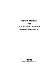
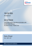
3-1. PCL6113
60
OUT
DIR
ERC
BSY
GND
(GND)
(GND)
VDD
CLK
GND
(GND)
(GND)
VDD
CSD
CSTA
CSTP
CEMG
ELL
RST
GND
56
58
54
52
50
46
48
42 40
44
PCS
ALM
ORG
SD
-EL
+EL
VDD
D15
D14
D13
D12
GND
D11
D10
D9
D8
VDD
D7
D6
D5
62
38
64
36
66
34
68
32
PCL6113
70
30
72
28
74
26
76
24
78
22
4
6
8
10
12
14
16
18
20
IF0
IF1
VDD
CS
RD
WR
A0
A1
A2
GND
INT
WRQ
IFB
VDD
D0
D1
D2
D3
GND
D4
80 2
BSYy
ERCy
DIRy
OUTy
VDD
P7y
P6y
P5y
P4y/CP2y
GND
P3y/CP1y
P2y/MVCy
P1y/FDWy
P0y/FUPy
VDD
PEy
PBy/-DRy
PAy/+DRy
EZy
EBy
EAy
GND
LTCy
INPy
PCSy
ALMy
ORGy
SDy
-ELy
+ELy
VDD
CP2x
CP1x
MVCx
FDWx
FUPx
GND
BSYx
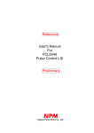
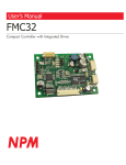
3-2. PCL6123
102 100
104
96
98
94
92
88
90
84
86
80
82
78
76
72
74
70
68
66 64
62
106
60
108
58
110
56
112
54
114
PCL6123
116
52
50
118
48
120
46
122
44
124
42
126
40
128
2
4
6
8
10
12
14
16
18
20
22
24
26
28
30
32
34
36
38
IF0
IF1
VDD
CS
RD
WR
A0
A1
A2
A3
GND
INT
WRQ
IFB
VDD
D0
D1
D2
D3
GND
D4
D5
D6
D7
VDD
D8
D9
D10
D11
GND
D12
D13
D14
D15
VDD
+ELx
-ELx
SDx
GND
FUPy
FDWy
MVCy
CP1y
CP2y
(OPEN)
(OPEN)
(OPEN)
VDD
CLK
GND
(GND)
(GND)
(GND)
(GND)
(GND)
VDD
CSD
CSTA
CSTP
CEMG
ELLx
ELLy
RST
GND
-5-
ERCx
DIRx
OUTx
VDD
P7x
P6x
P5x
P4x/CP2x
GND
P3x/CP1x
P2x/MVCx
P1x/FDWx
P0x/FUPx
VDD
PEx
PBx/-DRx
PAx/+DRx
EZx
EBx
EAx
GND
LTCx
INPx
PCSx
ALMx
ORGx
SDu
-ELu
+ELu
GND
BSYz
ERCz
DIRz
OUTz
VDD
P7z
P6z
P5z
P4z/CP2z
GND
P3z/CP1z
P2z/MVCz
P1z/FDWz
P0z/FUPz
VDD
PEz
PBz/-DRz
PAz/+DRz
EZz
EBz
EAz
GND
LTCz
INPz
PCSz
ALMz
ORGz
SDz
-ELz
+ELz
VDD
BSYy
ERCy
DIRy
OUTy
GND
P7y
P6y
P5y
P4y/CP2y
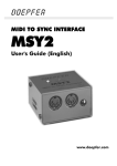
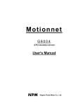
3-3. PCL6143
132 130 128 126 124 122
120 118 116 114 112
110 108 106 104 102 100
98
96
94
92
90
88
134
86
136
84
138
82
140
80
142
78
144
76
146
74
148
72
150
70
152
P CL 614 3
154
68
66
156
64
158
62
160
60
162
58
164
56
166
54
168
52
170
50
172
48
174
46
1762
4
6
8
10
12
14
16
18
20
22
24
26
28
30
32
34
36
38
40
42
44
VDD
P3y/CP1y
P2y/MVCy
P1y/FDWy
P0y/FUPy
GND
PEy
PBy/-DRy
PAy/+DRy
EZy
EBy
EAy
VDD
LTCy
INPy
PCSy
ALMy
ORGy
SDy
-ELy
+ELy
GND
BSYx
ERCx
DIRx
OUTx
VDD
P7x
P6x
P5x
P4x/CP2x
GND
P3x/CP1x
P2x/MVCx
P1x/FDWx
P0x/FUPx
VDD
PEx
PBx/-DRx
PAx/+DRx
EZx
EBx
EAx
GND
IF0
IF1
VDD
CS
RD
WR
A0
A1
A2
A3
A4
GND
INT
WRQ
IFB
VDD
D0
D1
D2
D3
GND
D4
D5
D6
D7
VDD
D8
D9
D10
D11
GND
D12
D13
D14
D15
VDD
+ELx
-ELx
SDx
ORGx
ALMx
PCSx
INPx
LTCx
ORGu
ALMu
PCSu
INPu
LTCu
VDD
EAu
EBu
EZu
PAu/+DRu
PBu/-DRu
PEu
GND
P0u/FUPu
P1u/FDWu
P2u/MVCu
P3u/CP1u
VDD
P4u/CP2u
P5u
P6u
P7u
GND
OUTu
DIRu
ERCu
BSYu
VDD
(GND)
GND
CLK
VDD
(GND)
(GND)
CSD
CSTA
CSTP
CEMG
ELLx
ELLy
ELLz
ELLu
RST
GND
Note: On the actual products, a mark similar to an indexing mark (O mark) may be printed on the LSI for
production reasons. The model name and the position of the 1st terminal are as shown in the terminal
allocation drawings. Identify the 1st terminal by the position of the O mark.
-6-
4. Functions of Terminals
Note 1:
Note 2:
Note 3:
Note 4:
Signal
name
GND
VDD
____
RST
CLK
IF0
IF1
The letter "n" at the end of each signal name stands for an axis name (x, y, z, or u). (Ex.: ELLn etc.)
In the "IN/OUT" column, "IN" indicates an input terminal and "OUT" indicates an output terminal.
"I/O" indicates a bi-directional terminal.
The logic column indicates the signal logic: Positive or Negative. "Positive" means positive logic and
“Negative” means negative logic. “P” means positive logic at default setting and can be changed
with software. "N" means negative logic at default and can be changed with software. "H" is a
hardware setting.
The "Handling" column describes how to deal with terminals when they are not used. (Some
terminals must be controlled, even when they are being used.)
"OP" means leave open (disconnected). "PU" means pull up. "PD" means pull down. "+V" must be
connected to VDD or pulled up. "GN" means a connection to GND. The pull up/down resistance
values should be in the range of 5 k to 10 k-ohms.
Terminal No.
IN/
Hand
Logic
Description
PCL
PCL
PCL
OUT
-ling
6113
6123
6143
10, 19,
11, 20,
12, 21,
IN
A negative power supply input.
29, 43,
30, 44,
31, 45,
Make sure to connect all of these terminals.
55, 65,
56, 66,
57, 67,
70, 80
81, 93,
83, 93,
103, 114 107, 119
128
129, 145
155, 162
176
3, 14,
3, 15, 25, 3, 16,26, IN
+3.3 VDC power supply input.
24, 34,
35, 51,
36, 52,
The allowable power supply range is +3.0 to 3.6 V .
50, 60,
61, 72,
62, 76,
Make sure to connect all of these terminals.
68, 73
88, 98,
88, 98,
112, 120 114, 124,
138, 150,
160, 164
79
127
175
IN
Nega
Reset signal input
-tive
Make sure to set this signal=L at least once after turning ON
the
power and before starting operation. Input and holding
____
RST =L level for at least 8 cycles of the reference clock.
For details about the LSI's status after a reset, see section
11-1. "Reset" in this manual.
69
113
163
IN
As standard, input a 19, 6608 MHz reference clock signal.
The LSI creates output pulses based on the clock input on
this terminal.
1
2
1
2
1
2
IN
-
-
___
CS
4
4
4
IN
Nega
-tive
-
___
RD
___
WR
5
6
5
6
5
6
IN
Negative
-
-7-
CPU-I/F mode setting
IF0
CPU
CPU signals to be connected to terminals
___
___
____
RD
WR
__
A0
____
WRQ
______
L
L
68000
(VDD)
___
R/ W
____
LDS
DTACK
____
L
H
H8
RD
___
HWR
___
(GND)
WAIT
H
L
8086
RD
___
WR
___
(GND)
READY
____
H
H
Z80
RD
WR
A0
WAIT
___
When the signal level on this terminal is L level, the RD and
___
WR terminals will be valid.
___
___
___
The RD and WR terminals are valid when CS terminal is L
level.
Terminal No.
Signal
Name
A0
A1
A2
A3
A4
___
INT
PCL
6113
PCL
6123
7
8
9
7
8
9
10
11
____
WRQ
PCL
6143
IN/
Hand
Logic
OUT
-ling
-
Description
IN
Posi
-tive
12
7
8
9
10
11
13
OUT
Nega OP
-tive
12
13
14
OUT
Nega OP
-tive
___
IFB
13
14
15
OUT
Nega OP
-tive
Signal used to indicate that the LSI is processing
commands
Use this signal to make connections with a CPU that does
not have a wait control input terminal.
When the LSI receives a write command from a CPU, this
signal will go L level. When the LSI finishes processing, this
signal will go H level.
Make sure that this terminal is H level before you access
next.
D0 to D3
15 to 18
16 to 19
17 to 20
I/O
-
D4 to D7
20 to 23
21 to 24
22 to 25
Posi
-tive
D8 to D11
I/O
Posi
-tive
PU
or
PD
Bi-directional data bus
When connecting a 16-bit data bus, connect the lower 8-bit
signal lines here.
Bi-directional data bus
When connecting a 16-bit data bus, connect the upper 8-bit
signal lines here.
In the case of 8-bit data bus (IF0=H, IF1=H), pull these
signals down to GND or up to VDD. (A single resistor can be
used by combining the lines.)
Input/output terminal for simultaneous deceleration
When performing multiple axis control using more than one
LSI, if you want to make____
the LSIs decelerate at the same
time, connect all of the CSD terminals to each other. Even
when using this signal, a pull up resistor to VDD is required.
The terminal status can be checked on the RSTS register
(extension status).
25 to 28
26 to 29
27 to 30
D12 to D15 30 to 33
31 to 34
32 to 35
____
CSD
74
121
167
I/O
Nega PU
-tive
_____
CSTA
75
122
168
I/O
Nega PU
-tive
-8-
Address bus input
For details about terminal A0, see the section describing
IF1 and IF0 terminals.
Interrupt request signal output to a CPU
There are three types of interrupt signals: a stop interrupt,
error interrupt, and an event interrupt. The interrupt type
can be determined by reading the main status MSTSW.
Each interrupt will be reset by reading MSTSW, REST, or
RIST.
___
The INT signal can be masked.
Wait request signal output to cause a CPU to wait
This LSI needs 4 reference clock cycles to process each
command.
____
___
If you will not be using the WRQ signal, check the IFB
terminal signal level so that you won't try to access the LSI
while
____ it is processing a command.
___
___
WRQ will be “L” only when CS =L and IFB=L.
Input/output terminal for simultaneous starts
When performing multiple axis control using more than one
LSI, if you_____
want to start the LSIs at the same time, connect
all of the CSTA terminals to each other. Even when using
this signal, a pull up resistor to VDD is required.
The terminal status can be checked on the RSTS register
(extension status).
Terminal No.
Signal
name
PCL
6113
IN/
Hand
Logic
OUT
-ling
Description
_____
CSTP
76
PCL
6123
123
PCL
6143
169
I/O
Nega PU
-tive
Input/output terminal for simultaneous stops
When performing multiaxis control using more than one
LSI, if you_____
want to stop the LSIs at the same time, connect
all of the CSTP terminals to each other. Even when using
this signal, a pull up resistor to VDD is required.
The terminal status can be checked on the RSTS register
(extension status).
_____
CEMG
77
124
170
IN
Nega +V
-tive
Emergency stop signal input
While this signal is L level, the LSI cannot start. If this signal
changes to L while in operation, the motors on all the axes
will stop operation immediately.
The terminal status can be checked on the RSTS register
(extension status).
Input logic setting for the +EL signal and –EL signal
L level: The input logic on +EL and –EL is positive.
H level: The input logic on +EL and –EL is negative.
ELL
(ELLn)
78
X: 125
Y: 126
X: 171
Y: 172
Z: 173
U: 174
IN
+EL
(+ELn)
35
X: 36
Y: 73
X: 37
Y :68
Z: 99
U: 130
IN
H
+V
End limit signal input in the positive (+) direction
When this signal is ON while feeding in the positive (+)
direction, the motor will stop immediately or will decelerate
and stop.
Specify the input logic using the ELL terminal.
The terminal status can be checked using an SSTSW
command signal (sub status).
-EL
(-ELn)
36
X: 37
Y: 74
X: 38
Y: 69
Z: 100
U: 131
IN
H
+V
End limit signal input in the negative (-) direction
When this signal is ON while feeding in negative (-)
direction, the motor on that axis will stop immediately, or will
decelerate and stop.
Specify the input logic using the ELL terminal.
The terminal status can be checked using an SSTSW
command signal (sub status).
SD
(SDn)
37
X: 38
Y: 75
X: 39
Y: 70
Z: 101
U: 132
IN
N
+V
Input deceleration (deceleration stop) signal
Selects the input method: Level or Latched inputs.
The input logic can be selected using software. The
terminal status can be checked using an SSTSW command
signal (sub status).
ORG
(ORGn)
38
X: 39
Y: 76
X: 40
Y: 71
Z: 102
U: 133
IN
N
+V
Origin position signal input
Used for origin return. (Edge detection.)
The input logic can be selected using software. The
terminal status can be checked using an SSTSW command
signal (sub status).
ALM
(ALMn)
39
X: 40
Y: 77
X: 41
Y: 72
Z: 103
U: 134
IN
N
+V
Alarm signal input
When this signal is ON, the motor on that axis stops
immediately, or will decelerate and stop.
The input logic can be selected using software.
The terminal status can be checked using an SSTSW
command signal (sub status).
PCS
(PCSn)
40
X: 41
Y: 78
X: 42
Y: 73
Z: 104
U: 135
IN
N
GN
The LSI will start positioning when this signal turns ON.
(Target position override 2)
The input logic can be changed using software.
The terminal status can be checked using the RSTS
(extension status) register.
-9-
Terminal No.
Signal
name
PCL
6113
PCL
6123
X: 42
Y: 79
PCL
6143
X: 43
Y: 74
Z: 105
U: 136
INP
(INPn)
41
LTC
(LTCn)
42
X: 43
Y: 80
EA
(EAn)
44
EB
(EBn)
EZ
(EZn)
IN/
Hand
Logic
OUT
-ling
Description
IN
N
GN
Position complete signal input from servo driver (in-position
signal)
The input logic can be changed using software.
The terminal status can be checked using the RSTS
(extension status) register.
X: 44
Y: 75
Z: 106
U: 137
IN
N
GN
Latch counter value of COUNTER 1 and COUNTER 2
The input logic can be changed using software.
The terminal status can be checked using the RSTS
register.
X: 45
Y: 82
X: 46
Y: 77
Z: 108
U: 139
IN
-
GN
45
X: 46
Y: 83
X: 47
Y: 78
Z: 109
U: 140
Input this signal when you want to control the position using
the encoder signal. Input a 90-degree phase difference
signal (1x, 2x, 4x) or input positive (+) pulses on EA and
negative (-) pulses on EB.
When inputting 90-degree phase difference signals, if the
EA signal phase is ahead of the EB signal, the LSI will count
up pulses.
The counting direction can be changed using software.
46
X: 47
Y: 84
X: 48
Y: 79
Z: 110
U: 141
IN
N
GN
PA /+DR
47
(PAn/+DRn)
X: 48
Y: 85
X: 49
Y: 80
Z: 111
U: 142
IN
-
GN
PB/-DR
48
(PBn/-DRn)
X: 49
Y: 86
X: 50
Y: 81
Z: 112
U: 143
Input a marker signal (that is output once for each turn of
the encoder) when using the marker signal in origin return
mode.
Use of the EZ signal improves origin return precision.
The input logic can be changed by using software. The
terminal status can be checked by using the RSTS register
(extension status).
Common input used to trigger by either an external pulse
(PA, PB), such as a manual pulsar, or an external switch
(+DR, -DR)
The use of this input will vary with the operation mode
setting.
When inputting external pulses, you can input 90-degree
phase difference signals (1x, 2x, 4x) or positive (+) pulses
(on PA) and negative (-) pulses (on PB).
The relation between the input and feed direction can be
changed using software.
Setting these terminals L level enables PA/PB.
By inputting an axis change switch signal, one manual
pulsar or external switch can be used alternately for four
axes.
___ ____
PE ( PEn )
49
X: 50
Y: 87
X: 51
Y: 82
Z: 113
U: 144
IN
Nega GN
-tive
P0/FUP
51
X: 52
Y: 89
X: 53
Y: 84
Z: 115
U: 146
I/O
-
PD
Common terminal for general purpose I/O and FUP
When this terminal is used as a general-purpose I/O, you
can set it for input or output.
When used as an FUP terminal, it will output a signal while
accelerating.
The FUP output logic can be set using software.
52
X: 53
Y: 90
X: 54
Y: 85
Z: 116
U: 147
I/O
-
PD
Common terminal for general purpose I/O and FDW
When this terminal is used as a general-purpose I/O, you
can set it for input or output.
When used as an FDW terminal, it will output a signal while
decelerating.
The FDW output logic can be set using software.
(P0n/FUPn)
P1/FDW
(P1n/FDWn)
- 10 -
Terminal No.
Signal
name
PCL
6123
X: 54
Y: 91
PCL
6143
X: 55
Y: 86
Z: 117
U: 148
54
X: 55
Y: 92
56
P5
(P5n)
P2/MVC
PCL
6113
53
IN/
Hand
Logic
OUT
-ling
Description
I/O
-
PD
X: 56
Y: 87
Z: 118
U: 149
I/O
-
PD
X: 57
Y: 94
X: 58
Y: 89
Z: 120
U: 151
I/O
-
PD
57
X: 58
Y: 95
X: 59
Y: 90
Z: 121
U: 152
I/O
-
PD
P6
(P6n)
58
X: 59
Y: 96
X: 60
Y: 91
Z: 122
U: 153
I/O
-
PD
General-purpose I/O terminal
You can set it for input or output terminal using software.
P7
(P7n)
59
X: 60
Y: 97
X: 61
Y: 92
Z: 123
U: 154
I/O
-
PD
General-purpose I/O terminal
You can set it for input or output terminal using software.
OUT
(OUTn)
61
X: 62
Y: 99
OUT
N
OP
DIR
(DIRn)
62
X: 63
Y: 100
X: 63
Y: 94
Z: 125
U: 156
X: 64
Y: 95
Z: 126
U: 157
Outputs command pulses for controlling a motor.
The output specifications are determined by selecting the
common pulse mode, 2-pulse mode, or 90-degree phase
difference mode.
Set the output mode using software.
ERC
(ERCn)
63
X: 64
Y: 101
OUT
N
OP
____
BSY
_____
( BSYn )
X: 65
Y: 96
Z: 127
U: 158
Deviation counter clear signal ouput to a servo driver
The output logic and pulse width (Level output is also
available.) can be changed using software. The terminal
status can be checked using the RSTS register.
64
X: 65
Y: 102
OUT
Nega OP
-tive
This signal becomes L level during operation.
_____
FUPn
X: 66
Y: 97
Z: 128
U: 159
-
-
OUT
Nega OP
-tive
This signal becomes L level during acceleration.
_____
FDWn
X: 67
Y: 104
-
-
OUT
Nega OP
-tive
This signal becomes L level during deceleration.
_____
MVCn
X: 68
Y: 105
-
X: 69
Y: 106
-
OUT
Nega OP
-tive
This signal becomes L level during constant speed
operation.
(P2n/MVCn)
P3/CP1
(P3n/CP1n)
P4/CP2
(P4n/CP2n)
- 11 -
Common terminal for general purpose I/O and MVC.
When this terminal is used as a general-purpose I/O, you
can set it for input or output.
When used as an MVC terminal, it will output a signal during
operation at a constant speed.
The MVC output logic can be set using software.
Common terminal for general purpose I/O and CP1
When this terminal is used as a general-purpose I/O, you
can set it for input or output.
When used as a CP1 terminal, it will output a signal while
establishing the Comparator 1 condition.
The CP1 output logic can be set using software.
Common terminal for general purpose I/O and CP2
When this terminal is used as a general-purpose I/O, you
can set it for input or output.
When used as CP2 terminal, it will output a signal while
establishing the Comparator 2 condition.
The CP2 output logic can be set using software.
General-purpose I/O terminal
You can set it for input or output terminal using software.
Terminal No.
Signal
name
PCL
6113
_____
CP1n
-
_____
CP2n
-
(OPEN)
(GND)
PCL
6123
X: 70
Y: 107
PCL
6143
IN/
Hand
Logic
OUT
-ling
Description
-
OUT
Nega OP
-tive
This signal becomes L level while establishing the
Comparator 1 conditions.
X: 71
Y: 108
-
OUT
Nega OP
-tive
This signal becomes L level while establishing the
Comparator 2 conditions.
-
109,
110,
111
-
OUT
-
OP
Output terminal for checking the LSI when delivered
Do not make any connections to this terminal.
66,
67,
71,
72
115,
116,
117,
118,
119
161,
165,
166
IN
-
GN
Output terminal for checking when delivered
Connect it to GND.
- 12 -
5. Block Diagram
___ ___ ___ ____
CS , RD ,WR, RST
____ ____ ____
INT , IFB ,WRQ
IF0,1
A0 to 4
_____
CEMG
_____ _____ ____
CSTA, CSTP, CSD
CLK
VDD
GND
All axes
control
CPU-I/F
RUT,RDS
FH
correction
circuit
RCMP1
Comparator 1
RCMP2
ELLx
Register & control
Comparator 2
Linear
interpolation
curcuit
Control
pulse length
Selector
Multiplication
rate dividing
circuit
Pulser I/F
circuit
OUTx, DIRx
PAx, PBx
____
PEx
RCUN1
COUNTER 1
Position control
counter
Latch
RCUN2 control
Selector
Acceleration/
deceleration
pulse generation
circuit
RLTC1
COUNTER 2
Position control
counter
Latch
control
Encoder I/F
circuit
EAx, EBx
Selector
RFL,RFH,RUR,RDR
RMG
Selector
D0 to D15
RLTC2
RMV
Comparator 3
Position
control counter
RDP
ALMx
RPLS
Ramp down point
calculation circuit
PCSx
ERCx
Current speed
RSDC
Drive signal
INPx
+ELx, -ELx, SDx, ORGx
LTCx
____
BSYx
P0x to P7
Senior input
EXz
General-purpose port
[X axis circuit]
[Y axis circuit] (Identical of the X axis circuit)
This circuit only exists in the PCL6123 and CPL6143.
[Z axis circuit] (Identical of the X axis circuit)
This circuit only exists in the PCL6143
[U axis circuit] (Identical of the X axis circuit)
This circuit only exists in the PCL6143
- 13 -
6. CPU-I/F
6-1. Setting the CPU interface type
These LSIs contain the following 4 CPU interface types, in order to facilitate connection to various CPUs. To
select a specific type, use the IF0 and IF1 terminals.
Shown below are some circuit examples. To use some other CPU, select the appropriate interface after
referring to section "12-5. AC characteristics".
[Example of connections for CPU signals]
Setting status
CPU___
signal to connect to the terminals
Interface
CPU type ___
Name
IF1
IF0
RD terminal WR terminal
A0 ____
terminal
terminal
__
______
L
L
16-bit I/F-1
68000
(VDD)
R/
W
LDS
DTACK
___
____
____
L
H
16-bit I/F-2
H8
RD
HWR
(GND)
WAIT
___
___
H
L
16-bit I/F-3
8086
RD
WR
(GND)
READY
___
___
____
H
H
8-bit I/F
Z80
RD
WR
A0
WAIT
__
16-bit I/F-1: A 16-bit interface with an R/ W mode input, strobe input, and acknowledge output.
The lower addresses correspond to the upper word in the I/O buffer.
Convenient for use with VME bus and 68000 series CPUs.
16-bit I/F-2: A 16-bit interface with an RD input and a WR input.
The lower addresses correspond to the upper word in the I/O buffer.
Convenient for H8 series CPUs.
16-bit I/F-3: A 16-bit interface with an RD input and a WR input.
The lower addresses correspond to the lower word in the I/O buffer.
Convenient for use with 8086 series CPUs.
8-bit I/F:
An 8-bit interface with an RD input and a WR input.
The lower addresses correspond to the lower word in the I/O buffer.
Convenient for use with Z80 series CPUs.
6-2. Hardware design precautions
All of the input terminals can handle 0 to +5 V levels.
Although all of the output terminals can be pulled up to +5 V (through 5k ohms or more), they cannot output
3.3 V or more.
____
To reset the LSI, hold the RST =L, and input the CLK signals for at least 8-clock cycles.
Any unused terminals out of P0 to P7 should be pulled down to GND externally (5k to 10k ohms) or pulled up
to VDD.
When connecting a CPU with an 8-bit bus, D8 to D15 should be pulled down to GND externally (5 k to 10
k-ohm) or pulled up to VDD. (Shared use of one resister for the 8 lines is available.)
Use the ELL terminal to change the +EL and –EL signal input logic.
- 14 -
6-3. Examples of CPU-I/F
Note: When using the 16-bit I/F, the LSI can only access words (16 bits), not bytes (8 bits).
(1) 16-bit I/F-1 (IF1 = L, IF0 = L)
68000 CPU
___
AS
A5-A23
PCL6143
Decoding
circuit
CL
A1-A4
D0-D15
D0-D15
+3.3V
____
LDS
__
R/ W
______
DTACK
____ ____
IPL0- IPL2
CLK
IF0
___
CS
IF1
A1-A4
Interrupt
control
circuit
GND
___
RD
A0
___
WR
____
WRQ
____
INT
______
RESET
___________
System reset
____
RST
Note: The PCL6143 uses A1 to A4. The PCL6123 uses A1 to A3. The PCL6113 uses A1 to A2.
(2) 16-bit I/F-2 (IF1 = L, IF0 = H)
H8 CPU
A5-A23
PCL6143
CL
Decoding
circuit
A1-A4
CLK
___
CS
A1-A4
D0-D15
D0-D15
___
RD
____
HWR
_____
WAIT
____
IRQ
______
RESET
A0
___
RD
___
WR
____
WRQ
____
INT
____
RST
___________
System reset
+3.3V
IF0
IF1
GND
GND
Note: The PCL6143 uses A1 to A4. The PCL6123 uses A1 to A3. The PCL6113 uses A1 to A2.
- 15 -
(3) 16-bit I/F-3 (IF1 = H, IF0 = L)
8086 CPU
PCL6143
___
M/ IO
A16-A19
ALE
D0-D15
Address
Decoding
circuit
CL
CLK
___
CS
IF0
IF1
A1-A4
Latch
+3.3V
GND
D0-D15
A0
Interrupt
control
circuit
INTR
____
INTA
GND
____
INT
___
RD
___
WR
____
WRQ
____
RST
___
RD
___
WR
READY
RESET
+5V
___
MN/ MX
System reset
___________
System reset
Note: The PCL6143 uses A1 to A4. The PCL6123 uses A1 to A3. The PCL6113 uses A1 to A2.
(4) 8-bit I/F (IF1 = H, IF0 = H)
8086 CPU
___
MX
A5-A7
PCL6143
Decoding
circuit
CL
CLK
___
CS
A0-A4
A0-A4
D0-D7
____
IORG
___
RD
___
WR
D0-D7
+3.3V
IF0
IF1
___
RD
___
WR
____
WRQ
____
INT
____
RST
 ̄
WAIT
____
INT
______
RESET
___________
System reset
Note: The PCL6143 uses A0 to A4. The PCL6123 uses A0 to A3. The PCL6113 uses A0 to A2.
- 16 -
6-4. Address map
6-4-1. Axis arrangement map
In this LSI, the control address range for each axis is independent. It is selected by using address input
terminal A3 and A4, as shown below.
A4
0
0
1
1
A3
0
1
0
1
Detail
X axis control address range
Y axis control address range
Z axis control address range
U axis control address range
Note: The table on the left is for the PCL6143.
The PCL6123 does not have an A4 address
line. Only the X and Y axes are available.
The PCL6113 does not have A4 or A3 address
lines. Only the X axis is available.
6-4-2. Internal map of each axis
The internal map of each axis is defined by (A0,) A1 and A2 address line inputs.
<When 16-bit I/F-1 or 16-bit I/F-2 mode is selected>
1) Write cycle
A1 A2
Address bus
Processing detail
1
1
COMW
Specify an axis, write a control command.
Change the status of the general-purpose output port (only bits
1
0
OTPW
assigned as outputs are effective)
0
1
BUFW0
Write to the input/output buffer (bits15 to 0)
0
0
BUFW1
Write to the input/output buffer (bits 31 to 16)
2) Readout cycle
A1 A2
Address bus
1
1
MSTSW
1
0
SSTSW
0
1
BUFW0
0
0
BUFW1
Processing detail
Read the main status (bits 15 to 0)
Read the sub status and general-purpose I/O port.
Read from the input/output buffer (bits 15 to 0)
Read from the input/output buffer (bits 31 to 16)
<When 16-bit I/F-3 mode is selected>
1) Write cycle
A1 A2 Address bus
Processing detail
0
0
COMW
Write the axis assignment and control command
Change the status of the general-purpose output port (only bits
0
1
OTPW
assigned as outputs are effective)
1
0
BUFW0
Write to the input/output buffer (bits 15 to 0)
1
1
BUFW1
Write to the input/output buffer (bits 31 to 16)
2) Readout cycle
A1 A2 Address bus
0
0
MSTSW
0
1
SSTSW
1
0
BUFW0
1
1
BUFW1
Processing detail
Read the main status (bits 15 to 0)
Read the sub status or general-purpose input/output port
Read from the input/output buffer (bits 15 to 0)
Read from the input/output buffer (bits 31 to 16)
- 17 -
<When 8-bit I/F mode is selected>
1) Write cycle
A2 A1 A0 Address bus
Processing detail
0 0 0
COMB0
Write control commands
0 0 1
COMB1
Specify an axis (specify control command execution axis)
Change the status of the general-purpose output port (only bits
0 1 0
OTPB
assigned as outputs are effective)
0 1 1
(Invalid)
1 0 0
BUFB0
Write to the input/output buffer (bits 7 to 0)
1 0 1
BUFB1
Write to the input/output buffer (bits 15 to 8)
1 1 0
BUFB2
Write to the input/output buffer (bits 23 to 16)
1 1 1
BUFB3
Write to the input/output buffer (bits 31 to 24)
2) Read cycle
A2 A1 A0
0 0 0
0 0 1
0 1 0
0 1 1
1 0 0
1 0 1
1 1 0
1 1 1
Address bus
MSTSB0
MSTSB1
IOPB
SSTSB
BUFB0
BUFB1
BUFB2
BUFB3
Processing detail
Read the main status (bits 7 to 0)
Read the main status (bits 15 to 8)
Read the general-purpose output port
Read the sub status
Read from the input/output buffer (bits 7 to 0)
Read from the input/output buffer (bits 15 to 8)
Read from the input/output buffer (bits 23 to 16)
Read from the input/output buffer (bits 31 to 24)
- 18 -
6-5. Description of the map details
6-5-1. Write the command code and axis selection (COMB0, COMB1)
Write the commands for reading from and writing to registers and the start and stop control commands for
each axis.
COMB0:
Set the command code. For details, see “7. Command (Operation and Control commands).”
SELu to x: Select an axis for executing the command. If all of the bits are 0, its own axis (selected by A4 and
A3) is selected. To write the same command to more than one axis, set the bits of the selected
axes to 1. When you write to a register, the details of the input/output buffer are written into the
register for each axis. When you read from a register, the details in the register are written into
the input/output buffer for each axis.
COMW
COMB1
15
14
13
12
0
0
0
0
11
COMB0
10
9
8
7
6
5
4
3
2
1
0
SELu SELz SELy SELx
Note 1: Specifications using SELu to x are effective for all commands, not only register write/read
commands.
Note 2: The PCL6143 has SELx to u, and the PCL6123 has SELx to y. However, the PCL6113 does not
have COMB1.
There are two methods to write to a register, as follows. Mixed use of these methods is allowed. The example
below uses the PCL6143.
(1) Commands and data I/O are written as one set per axis, and a total of up to 4 sets can be used.
In this case, the axis specification (COMB1), other than starting or stopping an interpolation operation, is
performed using 00h.
However, if CSTA and CSTP signals are used to start or stop an interpolation operation, 00h can also be
used for this command.
When using multiple sets of PCL6113, 6123, or 6143 LSIs, a common program can be created easily.
<In the case 16-bit I/F=3>
A4 to A1
Symbol
“0000”b COMW_X
“0010”b BUFW0_X
“0011”b BUFW1_X
“0100”b COMW_Y
“0110”b BUFW0_Y
“0111”b BUFW1_Y
“1000”b COMW_Z
“1010”b BUFW0_Z
“1011”b BUFW1_Z
“1100”b COMW_U
“1110”b BUFW0_U
“1111”b BUFW1_U
Description
X axis command
X axis I/O buffer (bits 15 to 0)
X axis I/O buffer (bits 31 to 16)
Y axis command
Y axis I/O buffer (bits 15 to 0)
Y axis I/O buffer (bits 31 to 16)
Z axis command
Z axis I/O buffer (bits 15 to 0)
Z axis I/O buffer (bits 31 to 16)
U axis command
U axis I/O buffer (bits 15 to 0)
U axis I/O buffer (bits 31 to 16)
- 19 -
(2) Write the commands to common addresses, and write the data to the I/O area for each axis independently.
In this case, the axis must be specified for each command that is written. (However, the software reset
command (SRST) ignores any axis specification.)
One command writes/reads all the axes in the same register. Therefore the data setting time is reduced.
<In the case 16-bit I/F=3>
A4 to A1
Symbol
Description
“0000”b
COMW
Command
“0010”b
BUFW0_X X axis I/O buffer (bits 15 to 0)
“0011”b
BUFW1_X X axis I/O buffer (bits 31 to16)
“0110”b
BUFW0_Y Y axis I/O buffer (bits 15 to 0)
“0111”b
BUFW1_Y Y axis I/O buffer (bits 31 to 16)
“1010”b
BUFW0_Z Z axis I/O buffer (bits 15 to 0)
“1011”b
BUFW1_Z Z axis I/O buffer (bits 31 to 16)
“1110”b
BUFW0_U U axis I/O buffer (bits 15 to 0)
“1111”b
BUFW1_U U axis I/O buffer (bits 31 to 16)
Note: The examples above use COMW on the X axis. However, using COMW on any other axis can perform
the identical operation.
6-5-2. Write to an output port (OTPW, OTPB)
Specify output terminal status from the general purpose I/O terminals P0 to P7.
Bits corresponding to terminals not set as outputs are ignored.
When writing a word, the upper 8 bits are ignored. However, they should be set to 0 for future compatibility.
OTP7 to 0: Specify the status of output terminals P7n to P0n (n = x, y, z and u).
A H level signal is output to the terminal that the corresponding bit is set to 1.
OTPW
OTPB
15
14
13
12
11
10
9
8
0
0
0
0
0
0
0
0
7
6
5
4
3
2
1
0
OTP7 OTP6 OTP5 OTP4 OTP3 OTP2 OTP1 OTP0
6-5-3. Write/read the input/output buffer (BUFW, BUFB)
When you want to write data into a register, after placing the data in the input/output buffer, write a "register
write command" into COMB0. The data in the input/output buffer will be copied into the register.
When you want to read data in register, write a "register read command" into COMB0. The data in the register
will be copied to the input/output buffer. Then you can read the data from the input/output buffer.
The order for writing to and reading from buffers BUFW0 to 1 (BUFB0 to 3) is not specified. The data written in
the input/output buffer can be read.
BUFW1
BUFB3
BUFW0
BUFB2
BUFB1
BUFB0
31 30 29 28 27 26 25 24 23 22 21 20 19 18 17 16 15 14 13 12 11 10 9 8 7 6 5 4 3 2 1 0
- 20 -
6-5-4. Reading the main status (MSTSW, MSTSB)
MSTSW
MSTSB1
15
14
0
13
SPRF SEOR
MSTSB0
12
11
10
0
0
0
9
8
7
6
5
4
3
2
1
0
SCP2 SCP1 SSC1 SSC0 SINT SERR SEND SENI SRUN SSCM
Bit
0
1
2
Bit name
Details
SSCM Becomes 1 by writing a start command. Becomes 0 when the operation is stopped.
SRUN Becomes 1 by the start pulse output. Becomes 0 when the operation is stopped.
SENI
Stop interrupt flag
When IEND.RENV2=1, the LSI turns ON the INT output because the status changes
from operating to stop and the SENI bit becomes 1. (After the main status is read, it
returns to 0.) When IEND = 0, this flag will always be 0.
3
SEND
Becomes 0 by writing start command. Set to 1 when the operation is stopped.
4
SERR
Becomes 1 when an error interrupt occurs. Becomes 0 by reading the REST.
5
SINT
Becomes 1 when an event interrupt occurs. Becomes 0 by reading the RIST.
7 to 6 SSC1 to 0 Sequence number for execution or stopping.
8
SCP1
Becomes 1 when the COMPARATOR 1 comparison conditions are met.
9
SCP2
Becomes 1 when the COMPARATOR 2 comparison conditions are met.
12 to 10
Not defined (always 0)
-
13
SEOR When target position override cannot be executed (reading the RMV register while
stopped), this signal changes to 1. After the main status is read, it changes to 0.
14
SPRF
Becomes 1 when the pre-register for the subsequent operation data is full.
15
Not defined (always 0)
-
Status change timing chart
1) When the continuous mode (MOD=00h, 08h) is selected.
___
WR
Start command
Stop command
Read main status
___
RD
SSCM
SRUN
SENI
SEND
____
BSY
OUT
- 21 -
2) When the PA/ PB continuous mode (MOD=01h) is selected.
___
WR
Start command
Stop command
Read main status
___
RD
PA
PB
SSCM
SRUN
SENI
SEND
____
BSY
OUT
3) When the DR continuous mode (MOD=02h) is selected.
Start command
___
WR
___
RD
+DR
SSCM
SRUN
SENI
SEND
____
BSY
OUT
- 22 -
Stop command
Read main status
4) When the auto stop mode is selected such as positioning operation mode (MOD=41h).
Start command
___
WR
Read main status
___
RD
SSCM
SRUN
SENI
SEND
____
BSY
OUT
6-5-5. Reading the sub status and input/output port (SSTSW, SSTSB, IOPB)
SSTSW
SSTSB
15
14
13
12
11
IOPB
10
9
8
7
6
5
4
3
2
1
0
SSD SORG SMEL SPEL SALM SFC SFD SFU IOP7 IOP6 IOP5 IOP4 IOP3 IOP2 IOP1 IOP0
Bit
7 to 0
8
9
10
11
12
13
14
15
Bit name
IOP7 to 0
SFU
SFD
SFC
SALM
SPEL
SMEL
SORG
SSD
Description
Reads the status of P7 to 0 (0: L level, 1: H level)
Becomes 1 while accelerating.
Becomes 1 while decelerating.
Becomes 1 while feeding at constant speed.
Becomes 1 when the ALM input is ON.
Becomes 1 when the +EL input is ON.
Becomes 1 when the -EL input is ON.
Becomes 1 when the ORG input is ON.
Becomes 1 when the SD input is ON. (Latch signal of the SD input.)
- 23 -
7. Commands (Operation and Control Commands)
7-1. Operation commands
After writing the axis assignment data to COMB1 (address 1 when an 8-bit-I/F is used), write the command to
COMB0 (address 0 when an 8-bit-I/F is used), the LSI will start and stop, as well as change the speed of the
output pulses.
When any other interface mode is selected, the LSI will write 16-bit data including axis assignment and
commands.
7-1-1. Procedure for writing an operation command (the axis assignment is omitted)
Write a command to COMB0.
A waiting time of 4 reference clock cycles (approximately 0.2 us) is required for the following period.
A) interval between "writing a command" and "writing the next command,"
B) interval between "register writing command" and "writing the I/O buffer,"
C) interval between "register reading command" and "reading the I/O buffer."
____
When the WRQ output signal is used by connecting it to the CPU, the CPU automatically ensures this waiting
time.
If you want to use a CPU that does not have this
___ waiting function, arrange the program sequence so that
access is only allowed after confirming that the IFB output signal = H level.
____
1) When WRQ output is not used
1.
 ̄ output is not used
When WRQ
 ̄
CS
Writing a command
 ̄
WR
 ̄
CS
Writing a command
 ̄
WR
 ̄
RD
More than 4 reference clock
cycles by software
2.
 ̄ output is used
When WRQ
 ̄
CS
Writing a command
 ̄
WR
 ̄ ̄
IFB
 ̄ ̄
WRQ
 ̄
CS
 ̄
WR
Writing a command
 ̄
RD
 ̄ ̄
IFB
 ̄ ̄
WRQ
4
reference
clock
cycles
automatically
 ̄ signal is L level while CS
 ̄ and I ̄
Notes: WRQ
FB signals become L level.
- 24 -
7-1-2. Start command
1) Start command
If this command is written while the motor is stopped, the motor will start rotating. If this command is written
while the motor is operating, it is taken as the next start command.
COMB0
Symbol
Description
50h
STAFL FL constant speed start
51h
STAFH FH constant speed start
52h
STAD
High speed start 1 (FH constant speed -> deceleration stop) Note. 1
53h
STAUD High speed start 2 (Acceleration -> FH constant speed -> Deceleration stop)
Note. 1
Note 1: For details, see section 10-1, "Speed patterns."
2) Residual pulses start command
Write this command after the motor is stopped on the way to a positioning, it will continue movement for the
number of pulses left in the positioning counter.
COMB0
Symbol
Description
54h
CNTFL Residual pulses FL constant speed start
55h
CNTFH Residual pulses FH constant speed start
56h
CNTD High speed start 1 residual pulses (FH constant speed -> Deceleration stop)
57h
CNTUD High speed start 2 residual pulses (Acceleration -> FH constant speed ->
Deceleration stop)
3) Simultaneous start command
_____
By setting the RMD register, the LSI will start movement on an axis which is waiting for CSTA signal.
COMB0
Symbol
Description
_____
06h
CMSTA Output one shot of the start pulse from the_____
CSTA terminal.
2Ah
SPSTA Perform the same processing as when a CSTA signal is supplied, for its own
axis only.
7-1-3. Speed change command
Write this command while the motor is operating, the motor on that axis will change its feed speed. If this
command is written while stopped it will be ignored.
COMB0
Symbol
Description
40h
FCHGL Change to the FL speed immediately.
41h
FCHGH Change to the FH speed immediately.
42h
FSCHL Decelerate and change to the FL speed.
43h
FSCHH Accelerate and change to the FH speed.
- 25 -
7-1-4. Stop command
1) Stop command
Write this command to stop feeding while operating.
COMB0
Symbol
49h
STOP Write this command while in operation to stop immediately.
4Ah
SDSTP Write this command while feeding at FH constant speed or high speed, the
motor on that axis will decelerate to the FL constant speed and stop. If this
command is written while the axis is being fed at FL constant speed, the motor
on that axis will stop immediately.
2) Simultaneous stop command
_____
Stop the motor on any axis whose CSTP input stop function has been enabled by setting the RMD register.
COMB0
Symbol
Description
_____
07h
CMSTP Outputs one shot of pulses from the CSTP terminal to stop movement on that
axis.
3) Emergency stop command
Stops an axis in an emergency
COMB0
Symbol
Description
_____
05h
CMEMG Emergency stop (same as a CEMG signal input)
7-1-5. NOP (do nothing) command
COMB0
00h
Symbol
NOP
Description
This command does not affect the operation.
- 26 -
7-2. General-purpose output bit control commands
These commands control output of terminals P0 to P7 by bit.
When the terminals are designated as outputs, signals are output from terminals P0 to P7. Bits that
correspondents to terminals set as other than outputs are ignored.
The write procedures are the same as for the Operation commands.
In addition to this command, by writing to a general-purpose output port (OTPB: Address 2 when an 8-bit I/F
is used), you can set 8 bits as a group. See section “7-5. General-purpose output port control command.”
COMB0
10h
11h
12h
13h
14h
15h
16h
17h
Symbol
P0RST
P1RST
P2RST
P3RST
P4RST
P5RST
P6RST
P7RST
Description
COMB0
Makes P0 L level.
18h
Makes P1 L level
19h
Makes P2 L level.
1Ah
Makes P3 L level.
1Bh
Makes P4 L level.
1Ch
Makes P5 L level.
1Dh
Makes P6 L level.
1Eh
Makes P7 L level.
1Fh
- 27 -
Symbol
P0SET
P1SET
P2SET
P3SET
P4SET
P5SET
P6SET
P7SET
Description
Makes P0 H level.
Makes P1 H level.
Makes P2 H level.
Makes P3 H level.
Makes P4 H level.
Makes P5 H level.
Makes P6 H level.
Makes P7 H level.
7-3. Control command
Set various controls, such as the reset counter.
The procedures for writing are the same as the operation commands.
7-3-1. Software reset command
Resets this LSI.
COMB0 Symbol
Description
____
04h
SRST Software reset. (Same function as making the RST terminal L level.)
Note: After writing this command, do not access during 12 cycles of CLK.
7-3-2. Counter reset command
Resets counter value to zero.
COMB0
Symbol
20h
CUN1R Reset COUNTER 1.
21h
CUN2R Reset COUNTER 2.
Description
7-3-3. ERC output control command
Controls the ERC signal using commands.
COMB0
Symbol
Description
24h
ERCOUT Outputs the ERC signal.
25h
ERCRST Resets the output when the ERC signal output is specified to a level type output.
7-3-4. Pre-register control command
Cancels the pre-register settings.
See section "8-2. Pre-register" in this manual for details about the pre-register.
COMB0
Symbol
Description
26h
PRECAN Cancel the operation pre-register.
7-3-5. PCS input command
Entering this command has the same results as inputting a signal on the PCS terminal.
COMB0
Symbol
Description
28h
STAON Alternative to a PCS terminal input.
7-3-6. LTCH input (counter latch) command
Entering this command has the same result as inputting a signal on the LTC terminal.
COMB0
Symbol
Description
29h
LTCH Alternative to an LTC (latch counter) terminal input.
- 28 -
7-4. Register control command
By writing a Register Control command to COMB0 (Address 0 when an 8-bit-I/F is used), the LSI can copy
data between a register and the I/O buffer.
Note: When using the I/O buffer while responding to an interrupt, CPU should save I/O buffer data using
PUSH command on the stack and restore it using POP command from the stack after performing the interrupt
routine.
7-4-1. Procedure for writing data to a register (the axis assignment is omitted)
1) Write the data that will be written to a register into the I/O buffer (addresses 4 to 7 when an 8-bit I/F is used).
The order in which the data is written does not matter. However, secure two reference clock cycles (t1)
between these writings.
2) Then, write a "register write command" to COMB0 (address 0 when an 8-bit I/F is used).
After writing one set of data, wait at least
four cycles (approx. 0.2 us, t2) before writing the next set of data.
____
In both case 1) and case 2), when the WRQ output is connected to the CPU, the CPU wait control function
will provide the waiting time between write operations automatically.
A0 to A2
___
4h
5h
6h
7h
0h
CS
____
WRQ
D0 to D7
t1
t1
Data
1
t1
Data
1
t1
Data
1
t2
Data
1
Command
2
7-4-2. Procedure for reading data from a register (the axis assignment is omitted)
1) First, write a "register read out command" to COMB0 (address 4 to 7 when an 8-bit-I/F is used).
2) Wait at least four reference clock cycles (approx. 0.2 usec, t3) for the data to be copied to the I/O buffer.
3) Read the data from the I/O buffer (address 4 to 7 when an 8-bit-I/F is used). The order for reading data from
the I/O buffer does not matter. There is no minimum time between read operations.
____
When the WRQ output is connected to the CPU, the CPU wait control function will provide the waiting time
between write operations automatically.
A0 to A2
4h
0h
5h
6h
7h
 ̄
CS
 ̄
WR
 ̄
RD
D0 to D7
t3
Command
1
2
Data
Data
Data
Data
3
3
3
3
- 29 -
7-4-3. Table of register control commands
No.
Detail
1 Feed amount
2 Initial speed
Operation
3
speed
Acceleration
4
rate
Deceleration
5
rate
Speed
6 magnification
rate
Ramping-down
7
point
8 Operation mode
Linear
9 interpolation
main axis data
Acceleration
10
S-curve range
Deceleration
11
S-curve range
Environment
12
setting 1
Environment
13
setting 2
Environment
14
setting 3
COUNTER 1
15
(command)
COUNTER 2
16
(mechanical)
Comparison
17 data data for
comparator 1
Comparison
18 data for
comparator 2
Event INT
19
cause setting
COUNTER 1
20
latched data
COUNTER 2
21
latched data
Extension
22
status
Error INT cause
23
status
Event INT
24
cause status
Positioning
25
counter
EZ counter,
26 current speed
monitor
Ramping-down
27
point setting
Bit
Name
Register
Read command
Write command
COMB0 Symbol COMB0 Symbol
D0h
RRMV
90h
WRMV
D1h
RRFL
91h
WRFL
Pre-register
Read command
Write command
Name
COMB0 Symbol COMB0 Symbol
PRMV
C0h
RPRMV
80h
WPRMV
PRFL
C1h
RPRFL
81h
WPRFL
28
14
RMV
RFL
14
RFH
D2h
RRFH
92h
WRFH
PRFH
C2h
RPRFH
82h
WPRFH
14
RUR
D3h
RRUR
93h
WRUR
PRUR
C3h
RPRUR
83h
WPRUR
14
RDR
D4h
RRDR
94h
WRDR
PRDR
C4h
RPRDR
84h
WPRDR
12
RMG
D5h
RRMG
95h
WRMG
PRMG
C5h
RPRMG
85h
WPRMG
24
RDP
D6h
RRDP
96h
WRDP
PRDP
C6h
RPRDP
86h
WPRDP
30
RMD
D7h
RRMD
97h
WRMD
PRMD
C7h
RPRMD
87h
WPRMD
27
RIP
D8h
RRIP
98h
WRIP
PRIP
C8h
RPRIP
88h
WPRIP
13
RUS
D9h
RRUS
99h
WRUS
PRUS
C9h
RPRUS
89h
WPRUS
13
RDS
DAh
RRDS
9Ah
WRDS
PRDS
CAh
RPRDS
8Ah
WPRDS
32 RENV1
DCh
RRENV1
9Ch
WRENV1
-
-
-
-
-
31 RENV2
DDh
RRENV2
9Dh
WRENV2
-
-
-
-
-
22 RENV3
DEh
RRENV3
9Eh
WRENV3
-
-
-
-
-
28 RCUN1
E3h
RRCUN1
A3h
WRCUN1
-
-
-
-
-
28 RCUN2
E4h
RRCUN2
A4h
WRCUN2
-
-
-
-
-
28 RCMP1
E7h
RRCMP1
A7h
WRCMP1
-
-
-
-
-
28 RCMP2
E8h
RRCMP2
A8h
WRCMP2
-
-
-
-
-
13
RIRQ
ECh
RRIRQ
ACh
WRIRQ
-
-
-
-
-
28
RLTC1
EDh
RRLTC1
-
-
-
-
-
-
-
28
RLTC2
EEh
RRLTC2
-
-
-
-
-
-
-
17
RSTS
F1h
RRSTS
-
-
-
-
-
-
-
9
REST
F2h
RREST
-
-
-
-
-
-
-
14
RIST
F3h
RRIST
-
-
-
-
-
-
-
28
RPLS
F4h
RRPLS
-
-
-
-
-
-
-
20
RSPD
F5h
RRSPD
-
-
-
-
-
-
-
24
PSDC
F6h
RPSDC
-
-
-
-
-
-
-
- 30 -
7-5. General-purpose output port control command
By writing an output control command to the output port (OTPB: Address 2 when using an 8-bit-I/F), the LSI
will control the output of the P0 to P7 terminals.
When the I/O setting for P0 to P7 is set to output, the LSI will output signals from terminals P0 to P7 to issue
the command.
When writing words to the port, the upper 8 bits are discarded. However, they should be set to zero to
maintain future compatibility.
The output status of terminals P0 to P7 is latched, even after the I/O setting is changed to input.
The output status for each terminal can be set individually using bit control commands.
7-5-1. Command writing procedures
Write control data to output port (OTPB: Address 2 when an 8-bit-I/F is used).
To
continue with a next command, the LSI must wait for four reference clock cycles (approx. 0.2 usec). The
____
WRQ ____
terminal outputs a wait request signal.
If the WRQ terminal signal is not connected to CPU, please insure the interval by software or access after the
___
IFB output terminal is confirmed to be H level.
A0 to A2
2h
Next command address
 ̄
CS
WR
D0 to D7
Command
Command
 ̄ ̄
IFB
4 cycles of
Reference clock
Longer than 4 cycles
of reference clock
7-5-2. Command bit allocation
7
6
5
4
3
2
1
0
OTP7 OTP6 OTP5 OTP4 OTP3 OTP2 OTP1 OTP0
Output P0
Output P1
Output P2
Output P3
Output P4
Output P5
Output P6
Output P7
- 31 -
0 : L level
1 : H level
8. Registers
8-1. Table of registers
The following registers are available for each axis.
Register
Bit
No.
R/W
Details
name length
1
RMV
28
R/W Feed amount, target position
2
RFL
14
R/W Initial speed
3
RFH
14
R/W Operation speed
4
RUR
14
R/W Acceleration rate
5
RDR
14
R/W Deceleration rate
6
RMG
12
R/W Speed magnification rate
7
RDP
24
R/W Ramping-down point
8
RMD
30
R/W Operation mode
9
RIP
27
R/W Main axis feed amount during linear interpolation
10
RUS
13
R/W S-curve acceleration range
11
RDS
13
R/W S-curve deceleration range
12 RENV1
32
R/W Environment setting 1 (specify I/O terminal details)
13 RENV2
31
R/W Environment setting 2 (specify general-purpose port details)
14 RENV3
22
R/W Environment setting 3 (specify origin return and counter
details)
15 RCUN1
28
R/W COUNTER 1 (command position)
16 RCUN2
28
R/W COUNTER 2 (mechanical position)
17 RCMP1
28
R/W Comparison data for comparator 1
18 RCMP2
28
R/W Comparison data for comparator 2
19
RIRQ
13
R/W Specify event interrupt cause
20 RLTC1
28
R
COUNTER 1 (command position) latch data
21 RLTC2
28
R
COUNTER 2 (mechanical position) latch data
22
RSTS
17
R
Extension status
23
REST
9
R
Acquire Error INT cause status
24
RIST
14
R
Event INT cause status
25
RPLS
28
R
Positioning counter (number of residual pulses to feed)
26 RSPD
20
R
EZ counter, current speed monitor
27 RSDC
24
R
Ramping-down point setting value
- 32 -
Pre-register
name
PRMV
PRFL
PRFH
PRUR
PRDR
PRMG
PRDP
PRMD
PRIP
PRUS
PRDS
8-2. Pre-register
The following registers and start commands have pre-registers:
RMV, RFL, RFH, RUR, RDR, RMG, RDP, RMD, RIP, RUS and RDS.
The term pre-register refers to a register which sets the next set of operation data while the current step is
executing. This LSI has the following 2-layer structure and executes FIFO operation.
Change
Setting
Pre-register
Register
(PRMV etc.)
(RMV etc.)
Operation control circuit
Normally, operation data are written into the pre-register. Start command’s pre-register is for written only.
To change the current operation status, such as changing the speed, the new data are written into the
register.
The data will be shifted (copied) from the “pre-register” to the “register” at the end of an operation.
One set of operation data uses multiple pre-registers (PRMV, PRFH, etc.). If the current operation completes
before the next set of operation data has been placed in all of the pre-registers, the LSI may start with
incomplete data. In order to prevent this problem, the "determined/not determined" status is used.
When a start command is written, the other operation data is considered to be determined, and the LSI will
continue its operation immediately after the current operation is complete.
The writing and operating procedures for the pre-registers are shown below.
1) When both the pre-register and register are empty,
data that is written to the pre-register will also be
written to the register. (Data 1 not determined status).
2) By writing a start command, the contents of the
register are declared determined and the LSI will start
the operation.
3) During operation, write the next operation data to the
pre-register. (A subsequent set of data that is the
same as the previous set does not need to be written.)
Since the register is currently in the "determined"
status, the next set of operation data is only written to
the pre-register. (Data 2)
4) By writing a start command for the next operation, the
data in the pre-register is declared to be determined.
5) When the first operation is finished, the data is
transferred from the pre-register to the register. The
LSI will then start operation according to the next set
of operation data (Data 2).
Procedure
Reset
1)
2)
3)
4)
5)
6)
Pre-register
0 Not
determined
Not
determined
data 1
Not
determined
data 1
Not
determined
data 2
Register
0 Not
determined
Not
determined
data 1
Determined
data 2
Not
determined
data 2
Not
determined
data 2
SPRF
0
0
Determined
data 1
0
Determined
data 1
0
Determined
data 1
1
Determined
data 2
0
Not
determined
data 2
0
6) When that operation is complete, the data is again
transferred from the pre-register to the register. However, in this case the next set of operation data is "not
determined," and so the LSI stops operation.
- 33 -
In step (5) and (6) above, the data in the pre-register is "not determined," allowing you to write the next set of
operation data.
Data written to the pre-register when the data in the pre-register is already "determined" will be ignored.
When the pre-register is declared to be___
determined, MSTSW.SPRF=1.
Also, the LSI can be set to output an INT signal when the pre-register changes from "determined" to "not
determined" status by setting the RIRQ.IRNM register.
Further, in any of the following cases, the pre-register has a "not determined" status, so that you can cancel a
continuous start even if the current operation is finished.
1) Writing a pre-register cancel command (26h).
2) A stop ordered by using the immediate stop command (49h) or deceleration stop command (4Ah).
While in a positioning operation, when the deceleration stop command is written during auto deceleration,
the mechanical position reaches the target position. However, the pre-register is declared "not
determined" and the next operation will be cancelled.
3) When the LSI stops because of an error (When any of the bits 6 to 0 in the REST register changes to 1.)
Note: To automatically start the next operation using the data already in the pre-register, set the operation
complete timing to "end of cycle" (PRMD.METM=0). If the "end of pulse" (PRMD.METM=1) is selected,
the interval between the last pulse and the next operation's start pulse will be narrower: 14 x T CLK (TCLK:
Reference clock cycle).
For details, see section “11-3-2. Output pulse length and operation complete timing.”
- 34 -
8-3. Description of the registers
The initial values of all the registers and pre-registers are "0."
Please note that with some registers, a value of "0" is outside the allowable setting range.
Note 1: Bits marked with an "*" asterisk are ignored when written and return a "0" when read.
Note 2: Bits marked with an "&" are ignored when written. They will be the same as the uppermost bit in the
empty column when read. (Code Extension)
8-3-1. PRMV (RMV) register
These registers are used to specify the target position for positioning operations. RMV is the register for
PRMV.
31 30 29 28 27 26 25 24 23 22 21 20 19 18 17 16 15 14 13 12 11 10 9 8 7 6 5 4 3 2 1 0
& & & &
Setting range: -134,217,728 to +134,217,727.
By changing the RMV register while in operation, the target position can be overridden.
8-3-2. PRFL (RFL) register
These pre-registers are used to set the initial speed (stop seed) for high speed (with acceleration
/deceleration) operations.
RFL is the register for PRFL.
31 30 29 28 27 26 25 24 23 22 21 20 19 18 17 16 15 14 13 12 11 10 9 8 7 6 5 4 3 2 1 0
*
*
*
*
*
*
*
*
*
*
*
*
*
*
*
*
*
*
The setting range is 1 to 16,383. However, the actual speed [pps] may vary with the speed magnification rate
setting in the PRMG register.
8-3-3. PRFH (RFH) register
These pre-registers are used to specify the operation speed.
RFH is the register for PRFH. Write to this register to override operation speed.
31 30 29 28 27 26 25 24 23 22 21 20 19 18 17 16 15 14 13 12 11 10 9 8 7 6 5 4 3 2 1 0
*
*
*
*
*
*
*
*
*
*
*
*
*
*
*
*
*
*
The setting range is 1 to 16,383. However, the actual speed [pps] may vary with the speed magnification rate
set in the PRMG register.
8-3-4. PRUR (RUR) register
These pre-registers are used to specify the acceleration rate.
RUR is the register for PRUR.
31 30 29 28 27 26 25 24 23 22 21 20 19 18 17 16 15 14 13 12 11 10 9 8 7 6 5 4 3 2 1 0
*
*
*
*
*
*
*
*
*
*
*
*
*
*
*
*
Setting range is 1 to 16,383.
- 35 -
*
*
8-3-5. PRDR (RDR) register
These pre-registers are used to specify the deceleration rate.
RDR is the register for PRDR.
31 30 29 28 27 26 25 24 23 22 21 20 19 18 17 16 15 14 13 12 11 10 9 8 7 6 5 4 3 2 1 0
*
*
*
*
*
*
*
*
*
*
*
*
*
*
*
*
*
*
The normal setting range is 1 to 16,383.
When PRDR = 0, the deceleration rate will be the value set by PRUR.
Note: When automatic setting is selected for the ramp down point (PRMD.MSDP = 0), enter the same value
as used for the PRUR, or 0, in this register.
8-3-6. PRMG (RMG) register
These pre-registers are used to set the speed magnification rate.
RMG is the register for PRMG.
31 30 29 28 27 26 25 24 23 22 21 20 19 18 17 16 15 14 13 12 11 10 9 8 7 6 5 4 3 2 1 0
*
*
*
*
*
*
*
*
*
*
*
*
*
*
*
*
*
*
*
*
The setting range is 1 to 4,095.
Set the relationship between the speed register PRFL (RFL), PRFH (RFH) values and the operation speeds.
The actual operation speed [pps] is a product of the speed magnification rate and the speed register setting.
[Setting example when the reference clock is 19.6608 MHz]
Speed
Operation speed
Setting
magnification
Setting
setting range [pps]
rate
3999 (0F9Fh)
0.3
0.3 to 4,914.9
59 (003Bh)
2399 (095Fh)
0.5
0.5 to 8,191.5
23 (0017h)
1199 (04AFh)
1
1 to 16,383
11 (000Bh)
599 (0257h)
2
2 to 32,766
5 (0005h)
239 (00EFh)
5
5 to 81,915
2 (0002h)
119 (0077h)
10
10 to 163,830
1 (0001h)
Speed
Operation speed setting
magnification
range [pps]
rate
20
20 to 327,660
50
50 to 819,150
100
100 to 1,638,300
200
200 to 3,276,600
400
400 to 6,553,200
600
600 to 9,829,800
8-3-7. PRDP (RDP) register
These pre-registers are used to set a ramping-down point (deceleration start point) for positioning operations.
RDP is the register for PRDP.
31 30 29 28 27 26 25 24 23 22 21 20 19 18 17 16 15 14 13 12 11 10 9 8 7 6 5 4 3 2 1 0
# # # # # # # #
Bits marked with a "#" symbol are ignored when written and change their setting when read according to the
setting of PRMD.MSDP.
MSDP
Setting details
bit #
Setting range
Offset for automatically set values.
When a positive value is entered, the LSI will start deceleration
-8,388,608 to
0
earlier and the FL speed range will be used longer.
Same as bit 23.
+8,388,607
When a negative value is entered, the LSI will start deceleration
later and the speed will not reach the FL speed.
When number of pulses left drops to less than a set value, the
0 to
1
0
motor on that axis starts to decelerate.
+16,777,215
- 36 -
8-3-8. PRMD (RMD) register
These pre-registers are used to set the operation mode.
RMD is the register for PRMD.
15
0
14
13
12
11
10
9
8
7
MPCS MSDP METM MCCE MSMD MINP MSDE
31
30
0
0
29
28
27
MCD0 MCDE
0
26
25
24
6
5
4
0
23
3
2
1
0
18
17
16
MOD
22
21
20
19
MADJ MSPO MSPE MAX3 MAX2 MAX1 MAX0 MSY MSY0 MSN1 MSN0
Bits
Bit name
Description
Setting basic operation mode
6 to 0
MOD Set operation mode.
“000 0000”b (00h): Continuous positive rotation controlled by command control.
“000 1000”b (08h): Continuous negative rotation controlled by command control.
“000 0001”b (01h): Continuous operation controlled by pulsar (PA/PB) input.
“000 0010”b (02h): Continuous operation controlled by external signal (+DR/-DR) input.
“001 0000”b (10h): Positive rotation origin return operation.
“001 1000”b (18h): Negative rotation origin return operation.
“100 0001”b (41h): Positioning operation (specify the incremental target position)
“100 0111”b (47h): Timer operation
“101 0001”b (51h): Positioning operation controlled by pulsar (PA/PB) input.
“101 0110”b (56h): Positioning operation controlled by external signal (+DR/-DR) input.
“110 0010”b (62h): Continuous linear interpolation
“110 0011”b (63h): Linear interpolation
7
Not
(Always set 0)
defined
Optional setting items
8
MSDE
9
MINP
10
MSMD
11
MCCE
12
METM
13
MSDP
14
MPCS
0: SD input will be ignored. (Checking can be done with sub status and RSTS)
1: Decelerates (deceleration stop) by turning ON the input.
0: Delay using an INP input will be invalid. (Checking can be done with RSTS)
1: Completes operation by turning ON the INP input.
Specify an acceleration/deceleration type for high speed feed.
(0: Linear acceleration/deceleration. 1: S-curve acceleration/deceleration.)
1: Stop counting output pulses on COUNTER 1 and 2.
This is used to move a mechanical part without changing the position controlled by
the LSI
When “EA/EB input” is selected for the counter input selection (RENV3.CIS1, CIS2),
the LSI will not stop counting when this bit is set.
Specify the operation complete timing. (0: End of cycle. 1: End of pulse.)
When selecting continuous operation using the pre-register, select "end of cycle."
Specify the ramping-down point for high speed feed.
(0: Automatic setting. 1: Manual setting.)
Effective for positioning operations and linear interpolation feeding.
When automatic setting is selected, set PRUR = PRDR and PRUS = PRDS.
1: While in automatic operation, control the number of pulses after the PCS input is
turned ON. (Override 2 for the target position.)
15
Not
(Always set 0)
defined
17 to 16 MSN1 to 0 When you want to control an operation block, specify a sequence number using 2
bits. By reading the main status (MSTSW), a sequence number currently being
executed (SSC1 to 0) can be checked. Setting the sequence number does not affect
the operation.
19 to 18 MSY1 to 0 After writing a start command, the LSI will start an axis synchronization operation
based on other timing.
“00”b : Start immediately.
_____
“01”b : Start on a CSTA input (or command 06h, 2Ah).
- 37 -
Bits
Bit name
Description
“10”b : Start with an internal synchronous start signal.
“11”b : Start when a specified axis stops moving.
23 to 20 MAX3 to 0 Specify an axis to check for an operation stop when the value of MSY1 to 0 is “11”b.
Setting examples
“0001”b : Starts when the X axis stops.
“0010”b : Starts when the Y axis stops.
“0100”b : Starts when the Z axis stops.
“1000”b : Starts when the U axis stops.
“0101”b : Starts when both the X and Z axes stop.
“1111”b : Starts when all axes stop.
_____
24
MSPE 1: Deceleration stop or immediate stop by CSTP input.
This is used for a simultaneous stop with another axis when this other axis stops with
an error.
_____
25
MSPO 1: Outputs a CSTP (simultaneous stop) signal when stopping due to an error.
26
MADJ Specify an FH correction function. (0: ON. 1: OFF.)
27
Not
(Always set 0)
defined
____
28
MCDE 1: Decelerates when CSD input = L.
Set this bit to 1 to decelerate
simultaneously with other axes.
____
29
MCDO 1: Outputs a L level on the CSD terminal when decelerating or at FL constant speed.
31 to 30
Not
(Always set 0.)
defined
8-3-9. PRIP (RIP) register
This is a pre-register used to specify the number of pulses for the main axis feed in linear interpolation (the
absolute value of the longest feed axis is set as the PRMV value)
RIP is the register for PRIP.
31 30 29 28 27 26 25 24 23 22 21 20 19 18 17 16 15 14 13 12 11 10 9 8 7 6 5 4 3 2 1 0
*
*
*
*
*
- When PRMD.MOD (bits 6 to 0) register is set as shown below, the register is enabled.
“110 0010”b (62h): Continuous linear interpolation (continuous operation with the linear interpolation ratio).
“110 0011”b (63h): Linear interpolation.
- Setting range: 0 to +134,217,727
8-3-10. PRUS (RUS) register
These pre-registers are used to specify the S-curve range of the S-curve acceleration.
RUS is the register for PRUS.
31 30 29 28 27 26 25 24 23 22 21 20 19 18 17 16 15 14 13 12 11 10 9 8 7 6 5 4 3 2 1 0
*
*
*
*
*
*
*
*
*
*
*
*
*
*
*
*
*
*
*
The normal setting range is 1 to 8,191.
When 0 is entered, the value of (PRFH - PRFL)/2 will be calculated internally and applied.
- 38 -
8-3-11. PRDS (RDS) register
These pre-registers are used to specify the S-curve range of the S-curve deceleration.
RDS is the register for PRDS.
31 30 29 28 27 26 25 24 23 22 21 20 19 18 17 16 15 14 13 12 11 10 9 8 7 6 5 4 3 2 1 0
*
*
*
*
*
*
*
*
*
*
*
*
*
*
*
*
*
*
*
The normal setting range is 1 to 8,191.
When 0 is entered, the value of (PRFH - PRFL)/2 will be calculated internally and applied.
Note: Specify the same value for the PRUS register when automatic setting of the ramp down point is
selected (PRMD.MSDP = 0).
8-3-12. RENV1 register
This register is used for Environment setting 1. This is mainly used to set the specifications for input/output
terminals.
15
14
13
12
11
10
9
8
7
6
5
4
3
ERCL EPW2 EPW1 EPW0 EROR EROE ALML ALMM ORGL SDL SDLT SDM
31
30
29
28
27
26
25
24
23
22
21
2
1
0
ELM PMD2 PMD1 PMD0
20
19
18
17
16
PMSK PCSM INTM DTMF DRF FLTR DRL PCSL LTCL INPL FTM1 FTM0 STPM STAM ETW1 ETW0
Bits
2 to 0
Bit name
PMD2 to 0 Specify OUT output pulse details
PMD2 to 0
SDM
5
SDLT
DIR output
OUT output
DIR output
Low
“001”b
High
Low
“010”b
Low
High
“011”b
Low
High
“100”b
High
“111”b
4
OUT output
Operation in (-) direction
High
“110”b
ELM
Operation in (+) direction
“000”b
“101”b
3
Description
High
OUT
OUT
DIR
DIR
OUT
OUT
DIR
DIR
Low
Low
Specify the process to occur when the EL signal input is turned ON. (0: Immediate stop. 1:
Deceleration stop.) Note 1
Specify the process to occur when the SD signal input is turned ON. (0: Deceleration only.
1: Deceleration and stop.)
Specify the latch function of the SD signal input. (0: OFF. 1: ON.)
Turns ON when the SD signal width is short.
When the SD input is OFF at the start, the latch signal is reset.
The latch signal is also reset when SDLT= 0.
- 39 -
Bits
6
7
Bit name
Description
SDL
Specify the SD signal input logic. (0: Negative logic. 1: Positive logic.)
ORGL
Specify the ORG signal input logic. (0: Negative logic. 1: Positive logic.)
8
ALMM
9
ALML
10
EROE
11
14 to
12
15
17 to
16
18
19
21 to
20
22
23
24
25
26
27
28
29
30
31
Specify the process to occur when the ALM signal input is turned ON. (0: Immediate stop.
1: Deceleration stop.)
Specify the ALM signal input logic. (0: Negative logic. 1: Positive logic.)
1: Automatically
outputs an ERC signal when the motor is stopped immediately by a +EL,
_____
-EL, ALM, or CEMG input signal. However, the ERC signal is not output when a
deceleration stop occurs.
EROR 1: Automatically output the ERC signal when origin return is completed.
EPW2 to 0 Specify the output pulse width of the ERC signal. (when CLK=19.6608MHz)
“000”b : 11 to 13 us
“100”b : 11 to 13 ms
“001”b : 91 to 98 us
“101”b : 46 to 50 ms
“010”b : 360 to 390 us “110”b : 93 to 100 ms
“011”b : 1.4 to 1.6 ms “111”b : Level output
ERCL
Specify the ERC signal output logic. (0: Negative logic. 1: Positive logic.)
ETW1 to 0 Specify the ERC signal OFF timer time. (when CLK=19.6608MHz)
“00”b : 0 us
“01”b : 11 to 13 us
“10”b : 1.4 to 1.6 ms
“11”b : 93 to_____
100 ms
STAM
Specify the CSTA signal input type. (0: Level trigger. 1: Edge trigger.)
_____
STPM
Specify a stop method using CSTP input. (0: Immediate stop. 1: Deceleration stop.)
FTM1 to 0 Select features of +EL, -EL, SD, ORG, ALM, and INP filters.
“00”b : Pulse length shorter than 3.2 us are ignored. (when CLK=19.6608MHz)
“01”b : Pulse length shorter than 25 us are ignored. (when CLK=19.6608MHz)
“10”b: Pulse length shorter than 200 us are ignored. (when CLK=19.6608MHz)
“11”b : Pulse length shorter than 1.6 ms are ignored. (when CLK=19.6608MHz)
INPL
Specify the INP signal input logic. (0: Negative logic. 1: Positive logic.)
LTCL
Specify the operation edge for the LTC signal. (0: Falling edge. 1: Rising edge)
PCSL
Specify the PCS signal input logic. (0: Negative logic. 1: Positive logic.)
DRL
Specify the +DR, -DR signal input logic. (0: Negative logic. 1: Positive logic.)
FLTR
1: Apply a noise filter to the +EL, -EL, SD, ORG, ALM, or INP inputs.
When a noise filter is applied, signal pulses shorter than the pulse length specified by
FTM1 to 0 are ignored.
DRF
1: Apply a noise filter on the +DR, -DR, or PE inputs.
When a noise filter is applied, signals pulses shorter than 32 ms (CLK=19.6608MHz) are
ignored.
DTMF
1: Turn OFF the direction change timer (0.2 ms) function.
INTM
1: Mask an INT signal output. (Interrupt
_____ circuit can be changed.)
PCSM 1: Make the PCS signal input as CSTA signal for its own axis only.
PMSK
1: Masks output pulses
Note1: When a deceleration stop (RENV1.ELM = 1) is specified to occur when the EL signal input turns ON,
the motor will start the deceleration when the EL input is turned ON. Therefore, the motor will stop by
passing over the EL signal position. In this case, be careful to avoid collisions of mechanical systems.
- 40 -
8-3-13. RENV2 register
This is a register for the Environment 2 settings. Specify the function of the general-purpose port, EA/EB input,
and PA/PB input.
15
14
13
12
POFF EOFF CSPO P7M
31
0
30
29
IEND ORM
28
EZL
11
P6M
27
10
9
8
7
6
5
4
3
2
1
0
P5M P4M1 P4M0 P3M1 P3M0 P2M1 P2M0 P1M1 P1M0 P0M1 P0M0
26
25
24
23
22
21
20
19
18
17
16
EZD3 EZD2 EZD1 EZD0 PDIR PINF PIM1 PIM0 EDIR EINF EIM1 EIM0
Bits
1 to 0
Bit name
Description
P0M1 to 0 Specify the operation of the P0/FUP terminals
“00”b : General-purpose input
“01”b : General-purpose output
“10”b : Output the FUP (acceleration) signal with negative logic.
“11”b : Output the FUP (acceleration) signal with positive logic.
3 to 2 P1M1 to 0 Specify the operation of the P1/FDW terminals
“00”b : General-purpose input
“01”b : General-purpose output
“10”b : Output the FDW (deceleration) signal with negative logic.
“11”b : Output the FDW (deceleration) signal with positive logic.
5 to 4 P2M1 to 0 Specify the operation of the P2/MVC terminal.
“00”b : General-purpose input
“01”b : General-purpose output
“10”b : Output the MVC (constant speed feeding) signal with negative logic.
“11”b : Output the MVC (constant speed feeding) signal with positive logic.
7 to 6 P3M1 to 0 Specify the operation of the P3/CP1 terminals.
“00”b : General-purpose input
“01”b : General-purpose output
“10”b : Output the CP1 (satisfied the Comparator 1 conditions) signal with negative
logic.
“11”b : Output the CP1 (satisfied the Comparator 1 conditions) signal with positive
logic.
9 to 8 P4M1 to 0 Specify the operation of the P4/CP2 terminals.
“00”b : General-purpose input
“01”b : General-purpose output
“10”b : Output the CP2 (satisfied the Comparator 2 conditions) signal with negative
logic.
“11”b : Output the CP2 (satisfied the Comparator 2 conditions) signal with positive
logic.
10
P5M
Specify the operation of the P5 terminals.
0: General-purpose input
1: General-purpose output
11
P6M
Specify the operation of the P6 terminals.
0: General-purpose input
1: General-purpose output.
12
P7M
Specify the operation of the P7 terminals.
0: General-purpose input
1: General-purpose output
_____
13
CSPO 1: When the RMD/MSP0 = 1, the LSI will output a CSTA when the motor is stopped
with a command.
14
EOFF 1: Disables EA/EB input. (Also disables input error detection.)
15
POFF 1: Disables PA/PB input. (Also disables input error detection.)
17 to 16 EIM1 to 0 Specify the EA/EB input operation.
“00”b : Multiply a 90-degree phase difference by 1 (Count forward when the EA input
phase is ahead.)
“01”b : Multiply a 90-degree phase difference by 2 (Count forward when the EA input
phase is ahead.)
- 41 -
Bits
Bit name
Description
“10”b : Multiply a 90-degree phase difference by 4 (Count up when EA input phase is
ahead.)
“11”b : Count up when the EA signal rises, count down when the EB signal rises.
18
EINF 1: Apply a noise filter to EA/EB/EZ input.
Ignores pulse inputs less than 3 CLK signal cycles long.
19
EDIR 1: Reverse the counting direction of the EA/EB inputs.
21 to 20 PIM1 to 0 Specify the PA/PB input operation.
“00”b : Multiply a 90-degree phase difference by 1 (Count up when the PA input
phase is ahead.)
“01”b : Multiply a 90-degree phase difference by 2 (Count up when the PA input
phase is ahead.)
“10”b : Multiply a 90-degree phase difference by 4 (Count up when PA input phase is
ahead.)
“11”b : Count up when the PA signal rises, count down when the PB signal rises.
22
PINF 1: Apply a noise filter to PA/PB input.
Ignore pulse inputs less than 3 CLK signal cycles long.
23
PDIR 1: Reverse the counting direction of the PA/PB inputs.
27 to 24 EZD3 to 0 Specify an EZ count value to be used for origin return.
“0000”b (1st time) to “1111”b (16th time)
28
EZL
Specify EZ signal input logic. (0: Falling edge. 1: Rising edge.)
29
ORM Select an origin return method.
0: Origin return operation 0
- Immediately stops by turning the ORG input from OFF to ON. (Decelerates and
stops when at high speed.)
- COUNTER reset timing: When the ORG input changes from OFF to ON.
1: Origin return operation 1
- When the LSI is feeding at constant speed, after the ORG input turns from OFF to
ON it will stop immediately by finishing counting the specified number of the EZ
signals.
When the LSI is feeding at high speed, it will decelerate by turning the ORG input
from OFF to ON and then immediately stop by finishing counting the specified
number of the EZ signals.
- COUNTER reset timing: When finishing counting the specified number of the EZ
signals.
30
IEND 1: Outputs an INT signal when stopping, regardless of whether the stop was normal or
due to an error.
31
Not
(Always specify 0.)
defined
- 42 -
8-3-14. RENV3 register
This register is for environment setting 3. Specify the counter function, latch function, and simultaneous start
function.
15
14
13
12
11
10
9
8
7
6
5
4
3
2
1
0
C2S1 C2S0 C1S1 C1S0 C2RM CU2R LOF2 CU2L C1RM CU1R COF1 CU1L CU2H CU1H CIS2 CIS1
31
30
29
28
27
26
25
24
23
22
21
0
0
0
0
0
0
0
0
0
0
SYI1
Bit
0
Bit name
CIS1
1
CIS2
2
3
4
5
CU1H
CU2H
CU1L
LOF1
6
7
8
9
CU1R
C1RM
CU2L
LOF2
10
CU2R
11
C2RM
13 to 12 C1S1 to 0
15 to 14 C2S1 to 0
19 to 16 SYO3 to 0
21 to 20
SYI1 to 0
31 to 22 Not defined
20
19
18
17
16
SYI0 SYO3 SYO2 SYO1 SYO0
Description
Select input counted by COUNTER 1
0: Output pulse
1: EA/EB input
Select input counted by COUNTER 2
0: EA/EB input
1: Output pulse
1: Stops counting of COUNTER 1.
1: Stops counting of COUNTER 2.
1: Resets COUNTER 1 when latching the contents of COUNTER 1.
1: Stop latching the contents of COUNTER 1 with the LTC signal input. (Only
effective for software.)
1: Latches (and resets) COUNTER 1 when an origin return operation is complete.
1: Set COUNTER 1 to ring counter operation using Comparator 1.
1: Resets COUNTER 2 when latching the contents of COUNTER 2.
1: Stop latching the contents of COUNTER 2 with the LTC signal input. (Only
effective for software.)
1: Latches (and resets) COUNTER 2 when an origin return operation is complete.
1: Set COUNTER 2 to ring counter operation using Comparator 2.
Select a comparison method for Comparator 1
“00”b : Turn the comparator function off.
“01”b : RCMP1 data = Comparison counter
“10”b : RCMP1 data > Comparison counter
“11”b : RCMP1 data < Comparison counter
Select a comparison method for Comparator 2
“00”b : Turn the comparator function off.
“01”b : RCMP2 data = Comparison counter
“10”b : RCMP2 data > Comparison counter
“11”b : RCMP2 data < Comparison counter
Select the output timing for the internal synchronous signal.
“0001”b : When the Comparator 1 conditions are met.
“0010”b : When the Comparator 2 conditions are met.
“1000”b : When starting acceleration.
“1001”b : When ending acceleration.
“1010”b : When starting deceleration.
“1011”b : When ending deceleration.
Others: The internal synchronous signal is not output.
Specify which axis will provide the LSI with the internal synchronous signal.
“00”b : Internal synchronous signal output by the X axis.
“01”b : Internal synchronous signal output by the Y axis.
“10”b : Internal synchronous signal output by the Z axis.
“11”b : Internal synchronous signal output by the U axis
(Always set to 0.)
- 43 -
8-3-15. RCUN1 register
This register is used to set and read COUNTER 1.
Setting range: -134,217,728 to +134,217,727
31 30 29 28 27 26 25 24 23 22 21 20 19 18 17 16 15 14 13 12 11 10 9 8 7 6 5 4 3 2 1 0
& & & &
*
*
For details about the counters, see section "11-9. Counter."
8-3-16. RCUN2 register
This register is used to set and read COUNTER 2.
Setting range: -134,217,728 to +134,217,727
31 30 29 28 27 26 25 24 23 22 21 20 19 18 17 16 15 14 13 12 11 10 9 8 7 6 5 4 3 2 1 0
& & & &
8-3-17. RCMP1 register
Specify the comparison data for Comparator 1.
Setting range: -134,217,728 to +134,217,727
For details about the counters, see section "11-10. Comparator."
31 30 29 28 27 26 25 24 23 22 21 20 19 18 17 16 15 14 13 12 11 10 9 8 7 6 5 4 3 2 1 0
& & & &
8-3-18. RCMP2 register
Specify the comparison data for Comparator 2.
Setting range: -134,217,728 to +134,217,727
31 30 29 28 27 26 25 24 23 22 21 20 19 18 17 16 15 14 13 12 11 10 9 8 7 6 5 4 3 2 1 0
& & & &
- 44 -
8-3-19. RIRQ register
Enables event interruption cause.
Set bits to 1 that you want to enable event interrupts.
15
14
13
0
0
0
31
30
29
28
27
26
25
24
23
22
21
20
19
18
17
16
0
0
0
0
0
0
0
0
0
0
0
0
0
0
0
0
Bit
0
1
2
3
4
5
6
7
8
9
10
11
12
31 to 13
12
11
10
9
8
7
6
5
4
3
2
1
0
IRSA IRDR IRSD IROL IRLT IRC2 IRC1 IRDE IRDS IRUE IRUS IRNM IREN
Bit name
IREN
IRNM
IRUS
IRUE
IRDS
IRDE
IRC1
IRC2
IRLT
Description
Stopping normally.
When enabled to write to the pre-register.
Starting acceleration.
When ending acceleration.
When starting deceleration.
When ending deceleration.
When Comparator 1 conditions are met.
When Comparator 2 conditions are met.
When latching the count value with an LTC signal input.
(When RENV3.LOF1 = LOF2 = 1, an interrupt will not occur.)
IROL
When the ORG input is ON.
(When RENV3.CU1R = CU2R = 0, an interrupt will not occur.)
IRSD
When the SD input is ON.
(Even when the SD input is disabled by setting PRMD.MSDE = 0, an interrupt
will occur.)
IRDR
When the
__ +DR(PA) –DR(PB) input is changed.
(When PE_____
= H, the interrupt will not occur.)
IRSA
When the CSTA input is ON.
Not defined (Always set to 0.)
8-3-20. RLTC1 register
Latched data for COUNTER 1. (Read only.)
The contents of COUNTER1 are copied when triggered by the LTC, an ORG input, or an LTCH command.
Data range: -134,217,728 to +134,217,727
31 30 29 28 27 26 25 24 23 22 21 20 19 18 17 16 15 14 13 12 11 10 9 8 7 6 5 4 3 2 1 0
& & & &
For details about the counters, see section "11-9. Counter."
8-3-21. RLTC2 register
Latched data for COUNTER 2 (Read only.)
The contents of COUNTER 2 are copied when triggered by the LTC, an ORG input, or an LTCH command.
Data range: -134,217,728 to +134,217,727
31 30 29 28 27 26 25 24 23 22 21 20 19 18 17 16 15 14 13 12 11 10 9 8 7 6 5 4 3 2 1 0
& & & &
- 45 -
8-3-22. RSTS register
The extension status can be checked. (Read only.)
15
14
13
12
11
10
9
8
7
6
5
4
3
2
1
0
SINP SDIN SLTC SDRM SDRP SEZ SERC SPCS SEMG SSTP SSTA SCD CND3 CND2 CND1 CND0
31
0
30
0
29
0
28
0
27
0
26
0
25
0
24
0
23
0
Bit
3 to 0
22
0
21
0
20
0
19
0
18
0
17
0
16
SDIR
Bit name
Description
CND3 to 0 Reports the operation status.
“0000”b : Under stopped condition
“1000”b : Waiting for PA/PB input.
“0001”b : Waiting for _____
DR input
“1010”b : Feeding at FL constant
“0010”b : Waiting for CSTA input
speed.
“0011”b : Waiting for an internal
“1011”b : Accelerating
synchronous signal
“1100”b : Feeding at FH constant
“0100”b : Waiting for another axis to stop.
speed.
“0101”b : Waiting for a completion of ERC “1101”b : Decelerating
timer
“1110”b : Waiting for INP input.
“0110”b : Waiting for a completion of
Others : (while controlling start/stop)
direction change
timer
____
4
SCD
Becomes 1 when the _____
CSD signal input is ON.
5
SSTA
Becomes 1 when the _____
CSTA signal input is turned ON.
6
SSTP
Becomes 1 when the CSTP
_____ signal input is turned ON.
7
SEMG
Becomes 1 when the CEMG signal input is turned ON.
8
SPCS
Becomes 1 when the PCS signal input is turned ON.
9
SERC
Becomes 1 when the ERC signal input is turned ON.
10
SEZ
Becomes 1 when the EZ signal input is turned ON.
11
SDRP
Becomes 1 when the +DR (PA) signal input is turned ON.
12
SDRM
Becomes 1 when the -DR (PB) signal input is turned ON.
13
SLTC
Becomes 1 when the LTC signal input is turned ON.
14
SDIN
Becomes 1 when the SD signal input is turned ON. (Status of SD input terminal.)
15
SINP
Becomes 1 when the INP signal input is turned ON.
16
SDIR
Operation direction (0: Positive direction, 1: Negative direction)
31 to 17 Not defined (Always set to 0.)
- 46 -
8-3-23. REST register
Used to check the error interrupt cause. (Read only.)
The corresponding bit will be "1" when an error interrupt occurs.
This register is reset when read.
15
0
14
0
13
0
12
0
11
0
10
0
9
0
31
0
30
0
29
0
28
0
27
0
26
0
25
0
Bit
0
1
2
8
7
6
5
4
3
2
1
0
ESPE ESEE ESP0 ESSD ESEM ESSP ESAL ESML ESPL
24
0
23
0
22
0
21
0
20
0
19
0
18
0
17
0
16
0
Bit name
ESPL
ESML
ESAL
Description
Stopped by the +EL input being turned ON.
Stopped by the -EL input being turned ON.
Stopped by turning the ALM input ON, or when an ALM input occurs while
stopping.
_____
3
ESSP
Stopped by the _____
CSTP input being turned ON.
4
ESEM
Stopped by the CEMG input being turned ON, or when an ALM input occurs while
stopping.
5
ESSD
Decelerated and stopped by the SD input being turned ON.
6
ESPO
An overflow occurred in the PA/PB input buffer counter.
7
ESEE
An EA/EB input error occurred. (The motor does not stop)
8
ESPE
A PA/PB input error occurred. (The motor does not stop)
31 to 9 Not defined (Always set to 0.)
8-3-24. RIST register
This register is used to check the cause of event interruption. (Read only.)
When an event interrupt occurs, the bits corresponding to the cause will be 1.
This register is reset when read.
15
0
14
0
31
0
30
0
13
12
11
10
9
8
7
6
5
4
3
2
1
0
ISSA ISMD ISPD ISSD ISOL ISLT ISC2 ISC1 ISDE ISDS ISUE ISUS ISNM ISEN
29
0
28
0
Bit
Bit name
0
ISEN
1
ISNM
2
ISUS
3
ISUE
4
ISDS
5
ISDE
6
ISC1
7
ISC2
8
ISLT
9
ISOL
10
ISSD
11
ISPD
12
ISMD
13
ISSA
31 to 14 Not defined
27
0
26
0
25
0
24
0
23
0
22
0
21
0
Description
When stopped automatically.
When available to write operation to pre-register.
When starting acceleration.
When ending acceleration.
When starting deceleration.
When ending deceleration.
When the comparator 1 conditions are met.
When the comparator 2 condition are met.
When the count value is latched by an LTC input.
When the count value is latched by an ORG input.
When the SD input turned ON.
When the +DR (PA) input changed.
When the -DR (PB) input changed.
When the _____
CSTA input turned ON.
(Always set to 0.)
- 47 -
20
0
19
0
18
0
17
0
16
0
8-3-25. RPLS register
This register is used to check the value of the positioning counter (number of pulses left for feeding). (Read
only.)
At the start of positioning operation, this value will be the absolute value in the RMV register. Each pulse that
is output will decrease this value by one.
Data range: 0 to 134,217,728
31 30 29 28 27 26 25 24 23 22 21 20 19 18 17 16 15 14 13 12 11 10 9 8 7 6 5 4 3 2 1 0
0 0 0 0
8-3-26. RSPD register
This register is used to check the EZ count value and the current speed. (Read only.)
15
0
14
0
31
0
30
0
Bit
13 to 0
13
12
11
10
9
8
7
AS13 AS12 AS11 AS10 AS9 AS8 AS7
29
0
28
0
27
0
26
0
25
0
24
0
23
0
6
5
4
3
AS6 AS5 AS4 AS3
22
0
21
0
20
0
2
1
0
AS2 AS1 AS0
19
18
17
16
ECZ3 ECA2 ECZ1 ECZ0
Bit name
AS13 to 0
Description
Read the current speed as a step value (same units as for RFL and RFH).
When stopped the value is 0.
15 to 14 Not defined (Always set to 0.)
19 to 16 ECZ3 to 0 Read the count value of EZ input that is used for an origin return.
31 to 20 Not defined (Always set to 0.)
8-3-27. RSDC register
This register is used to check the automatically calculated ramping-down point value for the positioning
operation. (Read only.)
31 30 29 28 27 26 25 24 23 22 21 20 19 18 17 16 15 14 13 12 11 10 9 8 7 6 5 4 3 2 1 0
0 0 0 0 0 0 0 0
The setting range will vary with the method used to set the ramp down point.
When automatic setting is selected, the available range is (the automatic set value + RDP set value). It is
expressed using 24 bits which are equal to -8,388,608 to +8,388,607. The value changes with the
acceleration/deceleration.
When manual setting is selected (PRMD.MSDP = 1), the range is 0 to +8,388,607 and a fixed value that is
equal to the RDP set value.
- 48 -
9. Operation Mode
Specify the basic operation mode using the PRMD.MOD (bits 6 to 0) (operation mode) register.
9-1. Continuous operation mode using command control
This is a mode of continuous operation. A start command is written and operation continues until a stop
command is written.
MOD
Operation method
Direction of movement
00h
Continuous operation from a command
Positive direction
08h
Continuous operation from a command
Negative direction
Operation is stopped by turning ON the EL signal corresponding to the direction of operation.
When operation direction is positive, +EL can be used. When operation direction is negative, -EL is used.
In order to start operation in the reverse direction after stopping the motion by turning ON the EL signal, a new
start command must be written.
9-2. Positioning operation mode
The following 2 operation types are available for positioning operations.
MOD
Operation method
Direction of movement
41h
Positioning operation
Positive direction when PRMV ≥ 0
Negative direction when PRMV < 0
47h
Timer operation (PRMV≥0)
Positive direction (DIR = H). However, the pulse
output is masked.
9-2-1. Positioning operation (MOD: 41h)
This is a positioning mode used by placing a value in the PRMV (target position) register.
The feed direction is determined by the sign set in the PRMV register.
When starting, the RMV register absolute setting value is loaded into the RPLS register. The LSI counts down
pulses with operations, and when the value of the positioning counter drops to 0, movement on the axes stops.
When you set the PRMV register value to zero to start a positioning operation, the LSI will stop outputting
pulses immediately.
9-2-2. Timer operation (MOD: 47h)
This mode allows the internal operation time to be used as a timer.
The internal effect of this operation is identical to the positioning operation. However, any pulses are not
output and they are masked. (The counter does not count.)
Therefore, the internal operation time using the constant speed start command will be a product of the
frequency of the output pulses and the RMV register setting. (Ex.: When the frequency is 1000 pps and the
RMV register is set to 120 pulses, the internal operation time will be 120 msec.)
Write a positive number (1 to 134,217,727) into the PRMV register. Negative numbers are treated as
unsigned positive numbers.
The +EL
signal, -EL signal,
SD input signal, and ALM signal are ignored. (These are always treated as OFF.)
_____
_____
The CSTP signal, and CEMG signals are effective.
The direction change timer function is stopped.
Regardless of the MINP setting (bit 9) in the RMD (operation mode) register, an operation complete delay
controlled by the INP signal will not occur.
In order to eliminate deviations in the internal operation time, set the PRMD.METM (bit 12) =0 and select "end
of cycle" as the operation complete timing.
- 49 -
9-3. Pulsar (PA/PB) input mode
This mode is used to allow operations from
__ a pulsar input.
In order to enable pulsar input, bring the PE terminal
L level. Set REMV2.POFF =0.
__
It is also possible to apply a noise filter on the PE input.
After writing a start command, when a pulsar signal is input, the LSI will output pulses to the OUT terminal.
Use an FL constant speed start (STAFL: 50h) or an FH constant speed start (STAFH: 51h) as a start
command.
Input pulsar signals on the PA and PB terminals. The input specification can be selected from the four
possibilities below by setting of the RENV2.PIM1 to 0.
- Supply a 90-degree phase difference signal (1x, 2x, or 4x).
- Supply count-up or countdown pulses (Two-pulse input).
Shown below are diagrams of the operation timing. (RENV1.PMD = “100”b --- When outputting 2 pulses)
1) When using 90-degree phase difference signals and 1x input (RENV2.PIM = “00”b)
PA
PB
 ̄
OUT
DIR
2) When using 90-degree phase difference signals and 2x input (RENV2.PIM = “01”b)
PA
PB
 ̄
OUT
DIR
3) When using 90-degree phase difference signals and 4x input (RENV2.PIM = “10”b)
PA
PB
 ̄
OUT
DIR
4) When using two pulse input. (RENV2.PIM = “11”b)
PA
PB
 ̄
OUT
DIR
- 50 -
The pulsar input mode is triggered by an FL constant speed start command (50h) or by an FH constant speed
start command (51h).
Pulsar input causes the LSI to output pulses with some pulses from the FL speed or FH speed pulse outputs
being omitted. Therefore, there may be a difference in the timing between the pulsar input and output pulses,
up to the maximum internal pulse frequency.
The maximum input frequency for pulsar signals (FP) is restricted by the FL speed when an FL constant
___
speed start is used, and by the FH speed when an FH constant speed start is used. The LSI outputs INT
signals as errors when both the PA and PB inputs change simultaneously and when the input/output buffer
counter (4 bits) overflows after the input frequency is exceeded. This can be monitored by the REST register.
FP <
setting speed
input I/F multiply value
Example: When the pulse input setting speed is 1000 pps with a 90-degree phase difference and a 2x input
multiply value, the input frequency on the PA terminal is less than 500 Hz.
FP cycle
(= FP1 )
PA
PB
Note: When the PA/ PB input frequency fluctuates, take the shortest frequency, not average frequency, as "
FP cycle" above.
<Setting relationship of PA/PB input>
Specify the PA/PB input
“00”b : 90-degree phase difference, 1x
“01”b : 90-degree phase difference, 2x
<RENV2.PIM0 to 1 (bit 21 to 20)> [RENV2]
(WRITE)
“10”b : 90-degree phase difference, 4x
23
16
“11”b : 2 pulse input
- - n n - - - -
Specify the PA/PB input count direction
<RENV2.PDIR (bit 23)> [RENV2]
(WRITE)
0: Count up when the PA phase is leading. Or, count up on the rising edge of PA. 23
16
1: Count up when the PB phase is leading. Or, count up on the rising edge of PB. n - - - - - - Enable/disable PA/PB input
0: Enable PA/PB input
1: Disable PA/PB input.
<RENV2.POFF (bit 15)> [RENV2]
(WRITE)
15
8
n - - - - - - -
___
Apply the +DR, -DR, PE input noise filter ___
<RENV2.DRF (bit 27)> [RENV1]
(WRITE)
1: Apply a noise filter on +DR, -DR and PE input
31
24
By setting the noise filter, the LSI ignores signals shorter than 32 msec.
- - - - n - - Reading operation status
<RSTS.CND (bit 3 to 0)> [RSTS]
(READ)
“1000”b : Wait for PA/ PB input.
7
0
- - - - n n n n
Reading PA/PB input error
ESPE (bit 17) = 1: A PA/PB input error occurs.
<REST.ESPE (bit 8)> [REST]
Reading PA/PB input buffer counter status
ESPO (bit 6) = 1: An overflow occurs.
<REST.ESP0 (bit 6)> [REST]
(READ)
15
8
0 0 0 0 0 0 0 n
(READ)
7
0
- n - - - - - -
* In the descriptions in the right hand column, "n" refers to a bit position. "0" refers to a bit position where it is
prohibited to write any value except zero and the bit will always be zero when read.
The pulsar input mode has the following 2 operation types.
- 51 -
The direction of movement for continuous operation can be changed by setting the RENV2 register, without
changing the wiring connections for the PA/PB inputs.
MOD
01h
51h
Operation mode
Continuous operation using pulsar input
Positioning operation using pulsar input
(incremental position)
Direction of movement
Determined by the PA/PB input.
Feeds in a positive direction when PRMV ≥ 0.
Feeds in a negative direction when PRMV <
0.
9-3-1. Continuous operation using a pulsar input (MOD: 01h)
This mode allows continuous operation using a pulsar input.
When PA/PB signals are input after writing a start command, the LSI will output pulses to the OUT terminal.
The feed direction depends on PA/PB signal input method and the value set in PDIR.
PA/PB input method
PDIR
Feed direction
PA/PB input
Positive direction
When the PA phase leads the PB phase.
0
90-degree phase difference
Negative direction
When the PB phase leads the PA phase.
signal
Positive direction
When the PB phase leads the PA phase.
(1x, 2x, and 4x)
1
Negative direction
When the PA phase leads the PB phase.
Positive direction
PA input rising edge.
0
Negative direction
PB input rising edge.
2 pulse input of up or down
pulse
Positive direction
PB input rising edge.
1
Negative direction
PA input rising edge.
The LSI stops operation when the EL signal in the current feed direction is turned ON. But the LSI can be
operated in the opposite direction without writing a___
restart command.
When stopped by the EL input, no error interrupt ( INToutput) will occur.
To release the operation mode, write an immediate stop command (49h).
9-3-2. Positioning operations using a pulsar input (MOD: 51h)
The positioning operation is synchronized with the pulsar input by using the PRMV setting as incremental
position data.
The feed direction is determined by the sign in the PRMV register.
At the start, the LSI loads the RMV register value into the positioning counter.
When PA/PB signals are input, the LSI outputs pulses and the positioning counter counts down. When the
value in the positioning counter reaches zero, movement will stop and another PA/ PB input will be ignored.
When you set PRMV register value to zero and start the positioning operation, the LSI will stop movement
immediately, without outputting any command pulses.
- 52 -
9-4. External switch operation mode
This mode allows operations with inputs from an external switch.
The external switch input terminals (+DR, -DR) are common with the pulsar signal input terminal. Apply a
positive direction switch signal to the PA/+DR terminal, and a negative direction switch signal to the PB/-DR
terminal.
___
To enable inputs from an external switch, bring the PE terminal L level.
After writing a start command, when a +DR and -DR signal is input, the LSI will output pulses to the OUT
terminal.
___
Set the RENVI register to specify the output logic of the ___
+DR and -DR signal. The INT signal can be set to
send an output when +DR and –DR input are changed. If PE = L, the LSI will output pulses regardless of the
operation mode selected.
The RSTS register can be used to check the operating status___
and monitor the +DR and –DR signals.
It is also possible to apply a noise filter to the +DR, -DR and PE inputs.
Set the input logic of the +DR and -DR signals
<RENV1.DRL (bit 25)>
0: Negative logic
1: Positive logic
___
Applying a noise filter to +DR, -DR and PE
<RENV1.DRF (bit 27)>
___inputs
1: Apply a noise filter to +DR, -DR and PE inputs
When a noise filter is applied, pulses shorter than 32 ms will be ignored.
Setting an event___
interrupt cause
<RIRQ.IRDR (bit 11)>
1: Output the INT signal when +DR and –DR signal input changed.
[RENV1]
(WRITE)
31
24
- - - - - - n [RENV1]
(WRITE)
31
24
- - - - n - - -
Reading the event interrupt cause
<RIST.ISPD (bit 11) and ISMD (bit 12)>
ISPD (bit 11) = 1: When the +DR signal input changes.
ISMD (bit 12) = 1: When the -DR signal input changes.
Read operation status
<CND (bits 3 to 0) in RSTS>
“0001”b : Waiting for a DR input
[RIST]
(READ)
15
8
0 0 - n n - - [RSTS]
(READ)
7
0
- - - - n n n n
[RIRQ]
(WRITE)
15
8
0 0 0 0 n - - -
Reading the +DR and -DR signals
<RSTS.SDRP (bit 11) and SDRM (bit 12)> [RSTS]
(READ)
SDRP = 0: +DR signal is OFF SDRP = 1: +DR signal is ON
15
8
SDRM = 0: -DR signal is OFF SDRM = 1: -DR signal is ON
- - - n n - - The external switch operation mode has the following two forms
MOD
Operation mode
02h
Continuous operation using an external switch.
56h
Positioning operation using an external switch.
Direction of movement
Determined by +DR, - DR input.
Determined by +DR, - DR input.
9-4-1. Continuous operation using an external switch (MOD: 02h)
This mode is used to operate a motor only when the DR signal is ON.
After writing a start command, turn the +DR signal ON to feed the motor in the positive direction, turn the -DR
signal ON to feed the motor in the negative direction, using a specified speed pattern.
By turning ON an EL signal for the feed direction, the motor will stop. However, the motor can feed in the
reverse direction. ___
An error interrupt ( INToutput) will not occur when the motor is stopped by the EL signal.
To end this operation mode, write an immediate stop command (49h).
If the motor is being fed with high speed commands (52h, 53h), the motor will decelerate and stop when the
DR signal turns OFF. If the DR signal for reverse direction turns ON while decelerating, the motor will
decelerate and stop. Then it will resume in the opposite direction.
[Setting example]
___
1) Bring the PE input “L”.
2) Specify PRFL, PRFH, PRUR, PRDR, and PRMG (speed setting).
3) Enter “0000010”b for PRMD.MOD (bits 6 to 0) register
4) Write a start command (50h to 53h).
RSTS.CND (bits 3 to 0) will wait for “0001”b (Wait for DR input).
In this condition, turn ON the +DR or -DR input terminal. The motor will rotate in the specified direction using
- 53 -
the specified speed pattern as long as the terminal is kept ON.
9-4-2. Positioning operation using an external switch (MOD: 56h)
This mode is used for positioning based on the DR signal turning ON.
At the start, the data in the RMV register is loaded into the positioning counter. When the DR signal is ON, the
LSI will output pulses and the positioning counter will start counting down pulses. When the positioning
counter value reaches zero, the LSI stops operation.
Even if the DR signal is turned OFF or ON again during the operation, it will have no effect on the operation. If
you make the REMV register value 0 and start a positioning operation, the LSI will stop operation immediately
without outputting any command pulses.
Turn ON the +DR signal to feed in the positive direction. Turn ON the -DR signal to feed in the negative
direction.
By turning ON the EL signal for the feed direction, the motor will stop. However, the motor can be feed in the
reverse direction. ___
An error interrupt ( INToutput) will not occur when the motor is stopped by the EL signal.
- 54 -
9-5. Origin return operation mode
Origin return operation varies with the PRMD.MOD setting, the RENV2.ORM setting and the type of start
command, as follows:
MOD
10h
ORM
0
COMB
50h
51h
53h
1
50h
51h
53h
18h
0
50h
51h
53h
1
50h
51h
53h
Operation description
Feeds in a positive direction at a FL constant speed and stops immediately
when the ORG input changes from OFF to ON.
Feeds in a positive direction at a FH constant speed and stops immediately
when the ORG input changes from OFF to ON.
Starts and accelerates from the FL to the FH speed in a positive direction
and starts deceleration when the ORG input changes from OFF to ON.
When the LSI has decelerated to the FL speed, it stops feeding pulses.
Also, if the LSI completes its deceleration to FL speed by a signal from the
SD input before the ORG input changes, the LSI will stop immediately when
the ORG input changes from OFF to ON.
Feeds in a positive direction at a FL constant speed. After the ORG input
changes from OFF to ON, the LSI stops operation immediately after
counting the specified number of EZ input signals.
Feeds in a positive direction at a FH constant speed. After the ORG input
changes from OFF to ON, the LSI stops immediately after counting the
specified number of EZ input signals.
Starts and accelerates from FL to FH speed in a positive direction. Starts to
decelerate when the ORG input changes from OFF to ON. After counting
the specified number of EZ input signals, the LSI stops.
Also, if the LSI completes its deceleration to FL speed by a signal from the
SD input before the ORG input changes, the LSI will stop soon after the
ORG input changes from OFF to ON, once it has counted the specified
number of EZ input signals.
Feeds in a negative direction at a FL constant speed and stops immediately
when the ORG input changes from OFF to ON.
Feeds in a negative direction at a FH constant speed and stops immediately
when the ORG input changes from OFF to ON.
Starts and accelerates from the FL to the FH speed in a negative direction
and starts deceleration when the ORG input changes from OFF to ON.
When the LSI has decelerated to the FL speed, it stops feeding pulses.
Also, if the LSI completes its deceleration to FL speed by a signal from the
SD input before the ORG input changes, the LSI will stop immediately when
the ORG input changes from OFF to ON.
Feeds in a negative direction at a FL constant speed. After the ORG input
changes from OFF to ON, the LSI stops immediately after counting the
specified number of EZ input signals.
Feeds in a negative direction at a FH constant speed. After the ORG input
changes from OFF to ON, the LSI stops immediately after counting the
specified number of EZ input signals.
Starts and accelerates from the FL to the FH speed in a negative direction
and starts deceleration when the ORG input changes from OFF to ON. After
counting the specified number of EZ inputs, the LSI stops.
Also, if the LSI completes its deceleration to FL speed by a signal from the
SD input before the ORG input changes, the LSI will stop soon after the
ORG input changes from OFF to ON, once it has counted the specified
number of EZ input signals.
- 55 -
Depending on the operation method, the origin position operation uses the ORG or EZ signals.
Specify the input logic of the ORG signal in the RENV1.ORGL. This register's terminal status can be
monitored with an SSTSW.SORG.
Specify the input logic and the number for EZ to count up of the EZ input signal in the RENV2.EZL and
RENV2.EZD. Status of this terminal can be monitored in the RSTS.SEZ.
You can apply an input filter to the ORG signal by setting the RENV1.FLTR and to the EZ signal by setting the
RENV2.EINF.
Selection of the origin return operation mode
0: Use only the ORG signal.
1: Use the ORG signal and EZ signals.
<RENV2.ORM (bit 29)> [RENV2]
(WRITE)
31
24
- - n - - - - -
Reading the ORG signal
0: Turn OFF the ORG signal.
1: Turn ON the ORG signal.
<SSTSW.SORG (bit 14)> [SSTSW]
(READ)
15
8
- n - - - - - -
Select input logic of the ORG signal
0: Negative logic.
1: Positive logic.
<RENV1.ORGL (bit 7)> [RENV1]
(WRITE)
7
0
n - - - - - - -
Apply an input noise filter to ORG and SD
<RENV1.FLTR (bit 26)> [RENV1]
(WRITE)
1: Apply a noise filter to the +EL, -EL, SD, ORG, ALM, and INP inputs.
31
24
When the filter is applied, signals which are shorter than the FTM pulse length will - - - - - n - be ignored.
Specify a time constant for the input filter
<RENV1.FLM (bit 21, 20)> [RENV1]
(WRITE)
“00”b : 3.2 µs
“10”b : 200 µs
23
16
“01”b : 25 µs
“11”b : 1.6 ms
- - n n - - - Reading the EZ signal
0: Turn OFF the EZ signal.
1: Turn ON the EZ signal.
Set the input logic for the EZ signal
0: Falling edge.
1: Rising edge
<RSTS .SEZ (bit 10)> [RSTS]
(READ)
15
8
- - - - - n - <RENV2.EZL (bit 28)> [RENV2]
(WRITE)
31
24
0 - - n - - - Apply an input filter to EA, EB, and EZ
<RENV2.INF (bit 18)> [RENV2]
(WRITE)
1: Apply a noise filter to these inputs.
23
16
Signals that are shorter than a CLK 3 cycle will be ignored.
- - - - - n - -
Specify an EZ count amount
<RENV2.EZD0 to 3 (bits 27 to 24)> [RENV2]
(WRITE)
Specify the number of EZ pulses needed to qualify for an origin return completion. 31
24
Specify the value (Number of pulses-1) in bits EZD3 to 0. Enter a number from 0 to 0 - - - n n n n
15.
When an origin return is complete, the LSI can latch (and reset) the counter and output an ERC (deviation
counter clear) signal.
The RENV3 register is used to set the basic origin return method. That is, whether or not to reset the counter
when the origin return is complete. Specify whether or not to output the ERC signal in the RENV1 register.
For details about the ERC signal, see “11-5-2. ERC signal.”
- 56 -
9-5-1. Origin return operation 0 (ORM = 0)
△:Timing when ERC signals are output with RENV1.EROR=1.
▲:Timing when ERC signals are output with RENV1.EROR=1
↑:Timing when Counter 1 (Counter 2) is latched (or reset)with RENV3.CU1R(CU2R).
□■Constant seed operation <Sensor: RENV1.ELM=0 or 1, ORG>
To output ERC signal when operation stops at the origin, set RENV1.EROR to 0.
To reset a counter at the origin position, set RENV3.CU1R(CU2R) to 1.
ORG
ON
EL
ON
Operation 1
Running
△
↑
Operation 2
Running
Operation 3
Error stop
Running
▲
Error stop
▲
■High speed operation <Sensor: RENV1.ELM = 0), ORG>
Even if the axis stops normally, it may not be at the origin position. However, COUNTER 2 (mechanical
position) provides a reliable value.
If ERC signal is output when operation stops at the origin, an error occurs on a counter value. Set
RENV1.EROR to 0.
To reset a counter at the origin position, set RENV3.CU1R(CU2R) to 1.
ORG
OFF
EL
OFF
Operation 1
ON
ON
Running
↑△
Operation 2
Error stop
▲
Operation 3
Error stop
▲
High speed operation <Sensor: EL (RENV1.ELM = 1), ORG>
Even if the axis stops normally, it may not be at the origin position. However, COUNTER 2 (mechanical
position) provides a reliable value.
If ERC signal is output when operation stops at the origin, an error occurs on a counter value. Set
RENV1.EROR to 0.
To reset a counter at the origin position, set RENV3.CU1R(CU2R) to 1.
When operation decelerates and stops at EL, ERC signal is not output.
ORG
OFF
EL
OFF
Operation 1
Operation 2
ON
Running
↑△
Error stop
Operation 3
Error stop
- 57 -
High speed operation <Sensor: EL (RENV1.ELM = 1), SD (RENV1.SDM = 0, RENV1.SDLT=0), ORG>
To output ERC signal when operation stops at the origin, set RENV1.EROR to 0.
To reset a counter at the origin position, set RENV3.CU1R(CU2R) to 1.
ORG
OFF
SD
OFF
EL
OFF
ON
ON
Operation 1
Operation 2
△
↑
Operation 3
Error stop
Operation 4
Error stop
9-5-2. Origin return operation 1 (ORM=1)
Constant speed operation <Sensor: EL (ELM = 0), ORG, EZ (EZD = “0001”b)>
ORG
OFF
ON
ON
EZ
EL
ON
Operation 1
Running
△
↑
Running
Operation 2
▲
Operation 3
Running
Error stop
Error stop
▲
High speed operation <Sensor: EL, ORG, EZ (EZD = “0001”b)>
ORG
OFF
ON
ON
EZ
ON
EL
Operation 1
Running
△
↑
Operation 2
Error stop
Running
Operation 3
Running
- 58 -
Error stop
9-6. Linear interpolation operation
9-6-1. Outline of interpolation operation
Using one or more LSIs, you can operate linear interpolation operation.
MOD
Operation mode
62h
Continuous linear interpolation
63h
Linear interpolation
Continuous linear interpolation operates on multi axes at a specified rate just like the linear interpolation, and
be started and stopped with commands like continuous mode.
In contrast, the operation automatically stops after feeding specified amount in linear interpolation.
The linear interpolation circuit in the LSI interpolates between a dummy axis associated with each axis and its
own axis.
By entering maximum feed amount data for each to every dummy axis, the LSIs will execute an indirect linear
interpolation between the axes.
As each interpolated axis operates independently, the start timing, deceleration timing, and error stop timing
must be matched between the axes.
When you want to use multiple LSIs and have them interpolate for each other, connect CSD, CSTA, and
CSTP terminals on each LSI to other same terminals on other LSI and provide a pull up resistor (5 k to 10
k-ohms) on VDD (3.3 V) for each signal line.
Even when performing interpolation within a single LSI, a pull up resistor is required for each terminal.
PCL61x3-1
 ̄
CSD
 ̄
CSTA
 ̄
CSTP
PCL61x3-2
 ̄
CSD
 ̄
CSTA
 ̄
CSTP
PCL61x3-3
 ̄
CSD
 ̄
CSTA
 ̄
CSTP
3.3V
5k to 10kΩ
9-6-2. Interpolation procedures
1) Enter a feed amount with a sign in the PRMV register for each axis. The sign specifies the feed direction.
2) Enter the absolute value of the PRMV (from the axis with the largest feed amount) in the PRIP registers of
all the axes that will perform an interpolation.
3) Specify the speed pattern (PRFL, PRFH, PRUR, PRMG, PRDP, PRDR, PRUS, PRDS) that will be used
for the axis with the maximum feed amount for all the axes that will perform an interpolation.
When you want to specify a synthesized speed, obtain the speed factor for the axis with the maximum feed
amount by calculation from the CPU. Then, enter this speed for all the axes that will perform an
interpolation.
4) If any of the axes performing an interpolation stops due to an error, and if you want to stop all the other
axes performing an interpolation, set the PRMD.MSPE and MSP0 on those axes to 1.
5) When you want to interpolate using acceleration/deceleration, set the PRMD.MCDE and MCD0 to 1 for all
the axes that will perform an interpolation.
6) When you want to perform an interpolation using only one LSI, specify the axis to interpolate in the upper
byte (COMB1) when writing the start command.
When you want to perform an interpolation using multiple LSIs, set the PRMD.MSY1 and 0 bits to “01”b, on all
the axes that will perform an interpolation. Then write a waiting for start command (waiting for a CSTA input).
- 59 -
After setting all the axes that will perform an interpolation to wait start, write the CSTA output command 06h
(simultaneous start) to any of these axes. All of the axes that will perform the interpolation will start at the
same time.
Other axes that are not interpolating can be operated independently.
[Setting example] Use the settings below and write a start command (0751h). The LSI will output pulses with
the timing shown in the figure below.
Setting
MOD
PRMV value
Operation speed
X axis
63h
5h
1000 pps
Y axis
63h
Ah
1000 pps
Z axis
63h
2h
1000 pps
X axis output pulse
1)
2)
3)
4)
5)
6)
7)
8)
9)
10)
Y axis output pulse
1000pps
Z axis output pulse
[Precision of linear interpolation]
As shown in the figure on the right,
linear interpolation executes an
interpolation from the current
coordinates to the end
coordinates.
The positional precision of a
specified line during linear
interpolation will be ±0.5 LSB
throughout the interpolation
range.
"LSB" refers to the minimum feed unit for the PRMV register setting. It corresponds to the resolution of the
mechanical system. (distance between squares in the figure on the right.)
- 60 -
9-6-3. Operation during interpolation
- Acceleration/deceleration operations
In addition to constant speed operation, these axes can accelerate/decelerate (linear acceleration or
S-curve), and a ramp down point with an automatic setting is also available.
However, the following restrictions are applied:
1) The settings for PRMD.MSDP and MADJ must be identical for all the axes that will perform an
interpolation.
2) If you want to use the manual setting (PRMD.MSDP = 1) for the ramp down point, enter the value for the
longest feed axis in the PRDP registers of all the axes that will perform an interpolation.
- Error stop
If any of the axes performing the interpolation stops on an error, the other axes performing an interpolation
will also stop by the CSTP terminal. Axes that did not encounter an error will show RSTS.ESSP = 1 when
read. This allows you to identify the axis that had an error.
- SD input
When SD input is enabled (PRMD.MSDE (bit 8)=1) by processing the CSD terminal, and if the SD input
turns ON on any of the axes, all axes will decelerate or decelerate and stop.
- Continuous interpolation
The LSI can use the pre-register to make a continuous linear interpolation.
Continuous interpolation refers to linear interpolation operations performed successively.
An example of the settings for continuous interpolation using the pre-register is shown in section “11-11-1.
Start triggered by another axis stopping.”
- 61 -
10. Speed patterns
10-1. Speed patterns
Speed pattern
FL constant speed
operation
f
Continuous mode
1) Write an FL constant speed start
command (50h).
Positioning operation mode
1) Write an FL constant speed start
command (50h).
2) Stop feeding by writing an
2) Stop feeding when the positioning
immediate stop (49h) or
counter reaches zero, or by writing an
deceleration stop (4Ah) command.
immediate stop (49h) or deceleration
stop (4Ah) command.
FL
t
1)
2)
FH constant speed
operation
f
FH
t
1)
2)
High speed operation 1)
f
1) Write an FH constant speed start
command (51h).
1) Write an FH constant speed start
command (51h).
2) Stop feeding by writing an
immediate stop command (49h).
2) Stop feeding when the positioning
counter reaches zero, or by writing an
immediate stop (49h) command.
* When the deceleration stop command (4Ah) is written to the register, the LSI
starts deceleration.
1) Write high speed start command 1 1) Write high speed start command 1
(52h).
(52h).
2) Start deceleration by writing a
2) Start deceleration when a ramping-down
deceleration stop command (4Ah).
point is reached or by writing a
deceleration stop command (4Ah).
* When the immediate stop command
FL
(49h) is written to the register, the LSI * When positioning with a high speed start
command 1 (52h), the ramping-down
t
immediately stops operation.
point is fixed to the manual setting,
1)
2)
regardless of the setting for
PRMD.MSDP (bit 13). If the
ramping-down point setting (PRDP) is 0,
the motor will stop immediately.
High speed operation 2)
1) Write high speed command 2 (53h). 1) Write high speed start command 2
(53h).
f
FH
2) Start deceleration by writing a
2) Start deceleration when a ramping-down
deceleration stop command (4Ah).
point is reached or by writing a
deceleration stop command (4Ah).
FH
FL
1)
2)
* When the immediate stop command *
t (49h) is written to the register, the LSI
immediately stops operation.
- 62 -
If the ramping-down point is set to
manual (PRMD.MSDP(bit 13) = 1), and
the ramping-down value (PRDP) is “0”,
the motor will stop immediately.
10-2. Speed pattern settings
Specify the speed pattern using the registers (pre-registers) shown in the table below.
If the next register setting is the same as the current value, there is no need to write to the register again.
Pre-register
Bit length
setting range
Description
PRMV
Positioning amount
28
PRFL
PRFH
PRUR
PRDR
PRMG
PRDP
PRUS
PRDS
Initial speed
Operation speed
Acceleration rate
Deceleration rate
Note 1
Speed magnification rate
Ramping-down point
S-curve acceleration range
S-curve deceleration range
14
14
14
14
12
24
13
13
Setting range
Register
-134,217,728 to 134,217,727
(8000000h)
(7FFFFFFh)
1 to 16,383
(3FFFh)
1 to 16,383
(3FFFh)
1 to 16,383
(3FFFh)
0 to 16,383
(3FFFh)
1 to 4,095
(0FFFh)
0 to 16,777,215 (0FFFFFFh)
0 to 8,191
(1FFFh)
0 to 8,191
(1FFFh)
RMV
RFL
RFH
RUR
RDR
RMG
RDP
RUS
RDS
Note 1: When PRDR = 0, the deceleration rate will be the value set in the PRUR.
[Relative position of each register setting for acceleration and deceleration factors]
Acceleration rate: Set in PRUR
f
Deceleration rate: Set in PRDR
FH speed : Set in PRFH, PRMG
S-curve Acceleration range:
Set in PRUS
Preset amount for positioning
operation : Set in PRMV
S-curve deceleration
range: Set in PRDS
FL speed : Set in PRFL, PRMG
t
t
Ramp-down point for positioning operation :
Set in PRDP or set automatically
- PRFL: FL speed setting register (14-bit)
Specify the speed for FL constant speed operations and the start speed for high speed operations
(acceleration/deceleration operations) in the range of 1 to 16,383 (3FFFh).
The speed will be calculated from the value in PRMG.
Reference clock frequency [Hz]
FL speed [pps] = PRFL x
(PRMG + 1) x 16384
- PRFH: FH speed setting register (14-bit)
Specify the speed for FH constant speed operations and the start speed for high speed operations
(acceleration/deceleration operations) in the range of 1 to 16,383 (3FFFh).
When used for high speed operations (acceleration/deceleration operations), specify a value larger than
PRFL.
The speed will be calculated from the value placed in PRMG.
Reference clock frequency [Hz]
FH speed [pps] = PRFH x
(PRMG + 1) x 16384
- 63 -
- PRUR: Acceleration rate setting register (14-bit)
Specify the acceleration characteristic for high speed operations (acceleration/deceleration operations), in
the range of 1 to 16,383 (3FFFh)
Relationship between the value entered and the acceleration time will be as follows:
1) Linear acceleration (PRMD.MSMD = 0)
(PRFH - PRFL) x (PRUR + 1) x 2
Acceleration time [s] =
Reference clock frequency [Hz]
2) S-curve without a linear range (PRMD.MSMD=1 and PRUS =0)
(PRFH - PRFL) x (PRUR + 1) x 4
Acceleration time [s] =
Reference clock frequency [Hz]
3) S-curve with a linear range (PRMD.MSMD=1 and PRUS >0)
(PRFH - PRFL + 2 x PRUS) x (PRUR + 1) x 2
Acceleration time [s] =
Reference clock frequency [Hz]
- PRDR: Deceleration rate setting register (14-bit)
Normally, specify the deceleration characteristics for high speed operations (acceleration/deceleration
operations) in the range of 1 to 16,383 (3FFFh).
To select the ramp down point auto setting (PRMD.MSDP = 0), set the PRDR register the same as PRUR
register setting, or enter 0.
When PRDR = 0, the deceleration rate will be the value placed in the PRUR.
The relationship between the value entered and the deceleration time is as follows.
1) Linear deceleration (MSMD = 0 in the PRMD register)
(PRFH - PRFL) x (PRDR + 1) x 2
Deceleration time [s] =
Reference clock frequency [Hz]
2) S-curve deceleration without a linear range (PRMD.MSMD=1 and PRDS = 0)
(PRFH - PRFL) x (PRDR + 1) x 4
Deceleration time [s] =
Reference clock frequency [Hz]
3) S-curve deceleration with a linear range (PRMD.MSMD=1 and PRDS >0)
(PRFH - PRFL + 2 x PRDS) x (PRDR + 1) x 2
Deceleration time [s] =
Reference clock frequency [Hz]
- PRMG: Magnification rate register (12-bit)
Specify the relationship between the PRFL and PRFH register settings and the speed, in the range of 1 to
4,095 (0FFFh). As the magnification rate is increased, the speed setting units will tend to be approximations.
Normally set the magnification rate to an appropriate small rate to fit for output speed range.
The relationship between the value entered and the magnification rate is as follows.
Reference clock frequency [Hz]
Magnification rate =
(PRMG + 1) x 16384
- 64 -
[Magnification rate setting example, when the reference clock =19.6608 MHz] (Output speed unit: pps)
Magnification
Output speed
Magnification
Output speed
Setting
Setting
rate
range
rate
range
3999 (0F9Fh)
0.3
0.3 to 4,914.9
59 (003Bh)
20
20 to 327,660
2399 (095Fh)
0.5
0.5 to 8,191.5
23 (0017h)
50
50 to 819,150
1199 (04AFh)
1
1 to 16.383
11 (000Bh)
100
100 to 1,638,300
599 (0257h)
2
2 to 32,766
5 (0005h)
200
200 to 3,276,600
239 (00EFh)
5
5 to 81,915
2 (0002h)
400
400 to 6,553,200
119 (0077h)
10
10 to 163,830
1 (0001h)
600
600 to 9,829,800
The maximum output speed of this IC can be attained when the reference clock is 30 MHz, PRMG = 1, and
PRFH = 16383.
In these conditions, the multiplication rate is 915.527x and the LSI will output 14.999 Mpps.
- PRDP: Ramping-down point register (24-bits)
Specify the value used to determine the deceleration start point for positioning operations that include
acceleration and deceleration.
The meaning of the value specified in the PRDP register varies according to setting of "ramping-down point
setting method" (PRMD.MSDP).
<When set to manual (PRMD.MSDP=1)>
Set the number of pulses at which to start deceleration, in the range of 0 to 16,777,215 (0FFFFFFh).
When the (PRDP set value) ≥ (Number of residual pulses), the LSI will start decelerating.
Note: In order to obtain the correct manual setting value, you have to know the actual maximum speed.
When there is only a small feed amount and the motor would have to decelerate while still
accelerating, or if the maximum speed is automatically modified by the FH correction function, the
LSI cannot calculate the manual setting value.
Therefore, in this case, turn OFF the FH correction function before trying the operation.
Alternatively, you can calculate the manual FH correction and then obtain the corrected maximum
speed using the following equations.
The optimum value of the ramping down position can be as follows.
1) Linear deceleration (PRMD.MSMD=0)
2
2
(PRFH - PRFL ) x (PRDR + 1)
Optimum value [Number of pulses]=
(PRMG + 1) x 16384
2) S-curve deceleration without a linear range (PRMD.MSMD=1 and the PRDS =0)
2
2
(PRFH - PRFL ) x (PRDR + 1) x 2
Optimum value [Number of pulses] =
(PRMG + 1) x 16384
3) S-curve deceleration with a linear range (PRMD.MSMD=1 and the PRDS >0)
(PRFH + PRFL) x (PRFH - PRFL + 2 x PRDS) x (PRDR + 1)
Optimum value [Number of pulses] =
(PRMG + 1) x 16384
Deceleration is started at the point that the (positioning counter value) ≤ (PRDP set value).
When the value for the ramping-down point is smaller than the optimum value, the speed when stopping will
be faster than the FL speed. On the other hand, if it is larger than the optimum value, the motor will feed at
FL constant speed after decelerating.
- 65 -
<When set to automatic (PRMD.MSDP = 0)>
This is an offset value for the automatically set ramping-down point. Set in the range of -8,388,608
(800000h) to 8,388,607 (7FFFFFh).
When the offset value is a positive number, the motor will start deceleration at an earlier stage and will feed
at the FL speed after decelerating. When a negative number is entered, the deceleration start timing will be
delayed.
If the offset is not required, set to zero.
- PRUS: S-curve acceleration range register (13-bit)
Specify the S-curve acceleration range for S-curve acceleration/deceleration operations in the range of 1 to
8,191 (1FFFh).
The S-curve acceleration range SSU will be calculated from the value placed in PRMG.
Reference clock frequency [Hz]
SSU [pps] = PRUS x
(PRMG + 1) x 16384
In other words, speeds between the FL speed and (FL speed + SSU), and between (FH speed - SSU) and the
FH speed, will be S-curve acceleration operations. Intermediate speeds will use linear acceleration.
However, if zero is specified, "(PRFH - PRFL)/2" will be used for internal calculations, and the operation will
be an S-curve acceleration without a linear component.
- PRDS: S-curve deceleration range setting register (13-bit)
Same as the PRUS, specify an S-curve deceleration range for the S-curve acceleration/deceleration
operation between 1 and 8,191 (1FFFh).
The S-curve acceleration range SSD will be calculated from the value placed in PRMG.
Reference clock frequency [Hz]
SSD [pps] = PRDS x
(PRMG + 1) x 16384
In other words, speeds between the FH speed and (FH speed - SSD), and between (FL speed + SSD) and the
FL speed, will be S-curve deceleration operations. Intermediate speeds will use linear deceleration.
However, if “0” is specified, "(PRFH - PRFL)/2" will be used for internal calculations, and the operation will
be an S-curve deceleration without a linear component.
- 66 -
10-3. Manual FH correction
When the FH correction function is turned ON (PRMD.MADJ = 0), and when the feed amount is too small for
a normal acceleration and deceleration operation, the LSI will automatically lower the FH speed to eliminate
triangle driving.
In addition, the ramp down point auto setting will also change according to the FH correction result.
However, the ramp down point auto setting function can only be used when the acceleration curve and
deceleration curve are symmetrical. In other words, if you want to make the acceleration and deceleration
curves asymmetrical, the ramp down point needs to be changed to a manual setting. In order to obtain the
correct manual setting value, you have to know the maximum speed.
Therefore, you have to turn OFF the FH correction function and manually correct the FH value.
pps
[FH correction function]
sec
Automatic correction of the maximum speed for changing the feed amount
- 67 -
< To execute FH correction manually>
1) Linear acceleration/deceleration speed (PRMD.MSMD=0)
When
2
2
(PRFH - PRFL ) x (PRUR + PRDR + 2)
PRMV ≤
(PRMG + 1) x 16384
,
PRFH ≤
(PRMG + 1) x 16384 x PRMV
PRUR + PRDR + 2
+ PRFL
2
2) S-curve acceleration without linear acceleration (PRMD.MSMD, PURS=0 and PRDS = 0)
When
2
2
(PRFH - PRFL ) x (PRUR + PRDR + 2) x 2
PRMV ≤
(PRMG + 1) x 16384
PRFH ≤
(PRMG + 1) x 16384 x PRMV
(PRUR + PRDR + 2) x 2
+ PRFL
2
3) S-curve acceleration/deceleration with linear acceleration/deceleration (PRMD.MSMD = 1, PRUS> 0, and
PRDS > 0)
(3)-1. When PRUS = PRDS
(i) Make a linear acceleration range smaller
When
(PRFH + PRFL) x (PRFH - PRFL + 2 x PRUS) x (PRUR + PRDR + 2)
PRMV ≤
and
(PRMG + 1) x 16384
PRMV >
(PRUS + PRFL) x PRUS x (PRUR + PRDR + 2) x 8
(PRMG + 1) x 16384
,
PRFH ≤ - PRUS +
2
(PRUS - PRFL) +
(PRMG + 1) x 16384 x PRMV
(PRUR + PRDR + 2)
(ii) Eliminate the linear acceleration/deceleration range
When
(PRUS + PRFL) x PRUS x (PRUR + PRDR + 2) x 8
PRMV ≤
(PRMG + 1) x 16384
,
Change to S-curve acceleration/deceleration without a linear acceleration/deceleration range (PRUS = 0,
PRDS = 0),
PRFH ≤
(PRMG + 1) x 16384 x PRMV
(PRUR + PRDR + 2) x 2
+ PRFL
2
Reference
PRMV: Positioning amount
PRFL: Initial speed
PRFH: Operation speed
PRUR: Acceleration rate
PRDR: Deceleration rate
PRMG: Speed magnification rate
PRUS: S-curve acceleration range PRDS: S-curve deceleration range
- 68 -
(3)-2. When PRUS < PRDS
(i) Make a linear acceleration/deceleration range smaller
When
(PRFH+PRFL)x{(PRFH-PRFL)x(PRUR+PRDR+2)+2xPRUSx(PRUR+1)+2xPRDSx(PRDR+1)}
PRMV ≤
(PRMG + 1) x 16384
and
PRMV >
(PRDS+PRFL) x {PRDS x (PRUR + 2 x PRDR + 3) + PRUS x (PRUR + 1)} x 4
(PRMG + 1) x 16384
,
2
PRFH ≤
-A + A + B
PRUR + PRDR + 2
However, A = PRUS x (PRUR + 1) + PRDS x (PRDR + 1)
B= {(PRMG + 1) x 16384 x PRMV - 2 x A x PRFL + (PRUR + PRDR + 2) x PRFL2} x (PRUR + PRDR + 2)
(ii) Eliminate the linear acceleration/deceleration range and make a linear acceleration section smaller.
When
(PRDS + PRFL) x {PRDS x (PRUR + 2 x PRDR + 3)} + PRUS x (PRUR +1 )} x 4
PRMV ≤
and
(PRMG + 1) x 16384
PRMV >
(PRUS + PRFL) x PRUS x (PRUR + PRDR + 2) x 8
(PRMG + 1) x 16384
Change to S-curve acceleration/deceleration without any linear acceleration/deceleration (PRUS>0,
PRDS=0)
2
PRFH ≤
-A + A + B
PRUR + 2 x PRDR + 3
However, A = PRUS x (PRUR + 1),
B= {(PRMG+1x16384xPRMV-2xAxPRFL+(PRUR+2xPRDR+3)xPRFL2}x(PRUR+2xPRDR+3)
(iii) Eliminate the linear acceleration/deceleration range
When PRMV ≤
(PRUS + PRFL) x PRUS x (PRUR + PRDR + 2) x 8
(PRMG + 1) x 16384
Change to S-curve acceleration/deceleration without any linear acceleration/deceleration (PRUS=0,
PRDS=0),
PRFH ≤
(PRMG + 1) x 16384 x PRMV
(PRUR + PRDR + 2) x 2
+ PRFL
2
Reference
PRMV: Positioning amount
PRFL: Initial speed
PRFH: Operation speed
PRUR: Acceleration rate
PRDR: Deceleration rate
PRMG: Speed magnification rate
PRUS: S-curve acceleration range PRDS: S-curve deceleration range
- 69 -
(3)-3. When PRUS>PRDS
(i) Make a linear acceleration/deceleration range smaller
When
(PRFH+PRFL)x{(PRFH-PRFL)x(PRUR+PRDR+2)+2xPRUSx(PRUR+1)+2xPRDSx(PRDR+1)}
PRMV ≤
(PRMG +1) x 16384
and
PRMV >
(PRUS + PRFL) x {PRUS x (2 x PRUR + PRDR + 3) + PRDS x (PRDR + 1) x 4
(PRMG + 1) x 16384
,
2
PRFH ≤
-A + A + B
PRUR + PRDR + 2
However, A = PRUS x (PRUR + 1) + PRDS x (PRDR + 1),
2}
B= {(PRMG + 1) x 16384 x PRMV - 2 x A x PRFL + (PRUR + PRDR + 2) x PRFL x (PRUR + PRDR + 2)
(ii) Eliminate the linear acceleration section and make a linear deceleration range smaller.
When
(PRUS + PRFL) x {PRUS x (2 x PRUR + PRDR + 3) + PRDS x (PRDR + 1)} x 4
PRMV ≤
(PRMG + 1) x 16384
PRMV >
(PRDS + PRFL) x PRDS x (PRUR + PRDR + 2) x 8
(PRMG + 1) x 16384
and
,
Change to S-curve acceleration/deceleration without any linear acceleration (PRUS = 0, PRDS > 0)
2
PRFH ≤
-A + A + B
2 x PRUR+ PRDR + 3
However, A = PRDS x (PRDR + 1),
2
B= {(PRMG+1)x16384xPRMV-2xAxPRFL+(2xPRUR+PRDR+3)xPRFL }x(2xPRUR+PRDR+3)
(iii) Eliminate the linear acceleration/deceleration range
When
(PRDS + PRFL) x PRDS x (PRUR + PRDR + 2) x 8
PRMV ≤
(PRMG + 1) x 16384
Change to S-curve acceleration/deceleration without any linear acceleration/deceleration (PRUS = 0,
PRDS = 0),
PRFH ≤
(PRMG + 1) x 16384 x PRMV
(PRUR + PRDR + 2) x2
+ PRFL
2
Reference
PRMV: Positioning amount
PRFL: Initial speed
PRFH: Operation speed
PRUR: Acceleration rate
PRDR: Deceleration rate
PRMG: Speed magnification rate
PRUS: S-curve acceleration range PRDS: S-curve deceleration range
- 70 -
10-4. Example of setting up an acceleration/deceleration speed pattern
Ex. Reference clock = 19.6608 MHz
When the start speed =10 pps, the operation speed =100 kpps, the accel/decel time = 300 ms, and linear
acceleration/deceleration is selected.
1) Select the 10x mode for magnification rate in order to get 100 kpps output
PRMG = 119 (0077h)
2) Since the 10x mode is selected to get an operation speed 100 kpps,
PRFH = 10000 (2710h)
3) In order to set a start speed of 10 pps, the magnification rate is set to the 10x mode.
PRFL = 1 (0001h)
4) In order to make the acceleration/deceleration time 300 ms, calculate from the equation for the acceleration
time and the PRUR setting value.
(PRFH - PRFL) x (PRUR + 1) x 2
Acceleration time [s] =
Reference clock frequency [Hz]
0.3 =
(10000 - 1) x (PRUR + 1) x 2
6
19.6608 x 10
∴PRUR = 293.94
However, since only integers can be entered for the PRUR register, use 293 or 294. The actual
acceleration/deceleration time will be 299.04 ms if PRUR = 293, or 300.06 ms if PRUR = 29.
5) Since the acceleration and deceleration times are equal, place 0 in the PRDR register and the deceleration
rate will be the same as the value in PRUR.
An example of the speed pattern when PRUR = 294
Speed
100kpps
(Operation speed)
10pps
(Start speed)
300.06 ms
300.06 ms
- 71 -
Time
10-5. Changing speed patterns while in operation
By changing the RFH, RUR, RDR, RUS, or RDS registers during operation, the speed and acceleration can
be changed.
An example of changing the speed pattern by changing the speed, during a linear acceleration/deceleration
operation
Speed
2)
3)
1)
Time
1)
Make RFH smaller while accelerating, the motor accelerates/decelerates until the speed reaches the
correct speed.
2),3) Change RFH after the acceleration/deceleration is complete. The motor will continue accelerating or
decelerating until the speed reaches the new speed.
An example of changing the speed pattern by changing the speed during S-curve acceleration/deceleration
operation
Speed
4)
2)
5)
3)
1)
Time
1)
If make RFH smaller and if ((changed speed) < (speed before change)), the motor will decelerate using
an S-curve until the speed reaches the correct speed.
5)
If make RFH smaller and if ((changed speed) ≥ (speed before change)), the motor will accelerate
without changing the S-curve's characteristic until the speed reaches the correct speed.
4)
If make RFH larger while accelerating, the motor will accelerate to the original speed entered without
changing the S-curve's characteristic. Then it will accelerate again until the speed reaches the newly
set speed.
2), 3) If RFH is changed after the acceleration/deceleration is complete, the motor will accelerate/decelerate
using an S-curve until the speed reaches the correct speed.
During positioning operation mode of Ramping-down automatic setting (PRMD.MSDP=0), there are the
following restrictions about operation speed override. If you set and execute without following the restriction,
function to set ramping-down point automatically cannot follow with operation and stop speed may be higher
than FL speed or moving at FL speed occurs after completing deceleration.
[During linear acceleration / deceleration]
1. Make acceleration and deceleration curves symmetric with RUR=RDR.
- 72 -
2. Only RFH can be changed during operation.
[During S-curve acceleration / deceleration]
Do not override operation speed.
11. Description of the Functions
11-1. Reset
After turning ON the power,
make sure to reset the LSI before beginning to use it.
____
To reset the LSI, hold the RST terminal “L” while supplying at least 8 cycles of a reference clock signal.
After a reset, the various portions of the LSI will be configured as follows.
Item
n = x, y, z, u
Internal registers, pre-register
Control command buffer
Axis assignment buffer
Input/output
buffer
___
INT
____terminal
WRQ terminal
___
IFB terminal
D0 to D7 terminals
D8 to D15 terminals
P0n
____to P7n terminals
CSD terminal
_____
CSTAterminal
_____
CSTP terminal
OUTn terminal
DIRn terminal
ERCn
_____ terminal
BSYn terminal
Reset status (initial status)
0
0
0
0
H level
H level
H level
Hi-Z
Hi-Z
Input terminal
H level
H level
H level
H level
H level
H level
H level
- 73 -
11-2. Target position override
This LSI can override (change the target position) freely during positioning operation.
However, the LSI cannot execute a target position override during linear interpolation.
There are two methods for overriding target position.
11-2-1. Target position override 1
If acceleration / deceleration characteristics are symmetric, target position can be overridden by change a
value of target position (RMV register value).
However, during S-curve acceleration / deceleration with ramping-down point automatic setting
(PRMD.MSDP=0), there are the following restriction. If you set and execute without following the restriction,
function to set ramping-down point automatically cannot follow with operation and stop speed may be higher
than FL speed or moving at FL speed occurs after completing deceleration.
- Do not change target position during acceleration / decoration.
- Set FH correction control OFF(RMD.MADJ = 1 ).
- You can override target position only at the timing the speed does not reach to ramping-down point during
acceleration / deceleration caused by target position override.
Change a target position by using a start position as a base.
1) If the new target position is further away from the
original target position during acceleration or
constant speed operation, the motor will maintain
the operation using the same speed pattern and it
will complete the positioning operation at the
position specified in the new target position (new
RMV value).
f
2) If the new target position is further away from the
original target position during deceleration, the
motor will accelerate from the current position to
FH speed and complete the positioning operation
at the position specified in the new target position
(new RMV value).
Assume that the current speed is Fu, and a curve
of the next acceleration will be equal to a normal
acceleration curve when RFL = Fu
f
3) If the machine position has already passed over the
new target position, or the target position is
changed to a position that is closer than the original
position during deceleration, the motor will
decelerate and stop. Then, the movement will
reverse and complete the positioning operation at
the new target position (new RMV value).
t
Change to a target
further away
t
Change to a target
further away
f
t
Change to a target
position already passed
Note1: When positioning while using acceleration/deceleration, even if the motor cannot decelerate to the FL
speed, it will stop at the specified position (placing a priority on the stop position). If the target position
override is applied and the LSI has to reverse feed, it will decelerate to the FL speed and then stop
(placing a priority on speed).
Therefore, it may possible that when a motor reverse is caused by the target position override, the
motor may feed pulses that cross over the target position and then reverse back to it.
- 74 -
Speed
Target position change
FH
Normally, movement stops without
decelerating to FL speed.
When the target point is overriden,
the axis decelerate to FL speed.
FL
Acceleration
Time
Deceleration
Note 2: If the LSI starts decelerating by changing the target to a closer position, and if you perform a “position
override” to a position further away during this deceleration, the LSI will not re-accelerate. It will feed
to the more distant target after decelerating to FL speed.
Note 3: The position override is only valid while feeding.
When the LSI receives an override command just a little before stopping a feed, it may not respond
to the override command. For this reason, check MSTSW.SEOR after the motor is stopped.
If the override is ignored, MSTSW.SEOR will become "1."
The LSI will set MSTSW.SEOR to "1" when it receives a command in the RMV register while feeding.
Therefore, if the command is written to the RMV register while stopped before feeding starts,
MSTSW.SEOR will also become "1." After reading the MSTSW, MSTSW.SEOR will return to "0"
within three CLK cycles.
11-2-2. Target position override 2 (PCS signal)
By setting PRMD.MPCS to "1," the LSI will perform positioning operations for the amount specified in the
PRMV register, based on the timing of this command after the operation start (after it starts outputting
command pulses) or on the "ON" timing of the PCS input signal.
A PCS signal can change the input logic. The PCS terminal status can be monitored using the RSTS register.
Setting pulse control using the PCS input
<PRMD.MPCS (bit 14)> [PRMD]
(WRITE)
1: Positioning for the number of pulses stored in the PRMV, starting from the time at 15
8
which the PCS input signal is turned ON.
- n - - - - - Setting the PCS input logic
0: Negative logic
1: Positive logic
<RENV1.PCSL (bit 24)> [RENV1]
(WRITE)
31
24
- - - - - - - n
Reading the PCS signal
< RSTS.SPCS (bit 8)> [RSTS]
(READ)
0: Turn OFF PCS signal
15
8
1: Turn ON PCS signal
- - - - - - - n
PCS substitution input
< Control command: STAON> [Control command]
Perform processes that are identical to those performed by supplying a PCS signal.
28h
- 75 -
11-3. Output pulse control
11-3-1. Output pulse mode
There are four types of common command pulse output modes and two types of 2-pulse modes, and two
types of 90-degree phase difference mode.
Common pulse mode:
Outputs operation pulses from the OUT terminal and outputs the direction
identification signal from the DIR terminal. (MOD = 000 to 011)
2-pulse mode:
Outputs positive direction operation pulses from the OUT terminal, and outputs
negative direction operation pulses from the DIR terminal. (MOD = 100, 111)
90-degree phase difference mode: This mode outputs signals from the OUT terminal and DIR terminal with
a 90-degree phase difference. (MOD = 101, 110)
The output mode for command pulses is set in RENV1.PMD (bits 2 to 0).
If motor drivers using the common pulse mode need a lag time (since the direction signal changes, until
receiving a command pulse), use a direction change timer.
When RENV1.DTMP (bit 28) is set to 0, the operation can be delayed for one direction change timer unit (0.2
ms), after changing the direction identification signal.
When RENV1.DTMF is 1, the LSI will start to output pulses 10 CLK cycles (0.5 us) after DIR changes.
Setting the pulse output mode
<RENV1.PMD2 to 0 (bits 2 to 0)>
When feeding in the
positive direction
PMD2 to 0
OUT output
DIR output
When feeding in the
negative direction
OUT output
DIR output
“000”b
High
Low
“001”b
High
Low
“010”b
Low
High
“011”b
Low
High
“100”b
“101”b
“110”b
“111”b
High
[RENV1]
7
(WRITE)
0
- - - - - n n n
High
OUT
OUT
DIR
DIR
OUT
OUT
DIR
DIR
Low
Low
Setting the direction change timer (0.2 ms) function
0: ON
1: OFF
- 76 -
<RENV1.DTMF (bit 28)> [RENV1]
(WRITE)
31
24
- - - n - - - -
11-3-2. Output pulse length and operation complete timing
Output pulse length is a 50% duty cycle.
When the PRMG setting is an even number, the duty cycle may deviate slightly and the ON time may be
shorter than the OFF time.
(Pulse ON time) / (Pulse cycle) = (PRMG set value / 2) / (PRMG set value +1)
Also, when setting PRMD.METM (operation completion timing setting), the operation complete timing can be
changed.
1) When PRMD.METM = 0 (the point at which the output frequency cycle is complete)
Output pulse cycle
15x TCLK
OUT
Last pulse
1st pulse of the next
operation
____
BSY
2) When PRMD.METM = 1 (when the output pulse is OFF)
TMIN
OUT
Last pulse
____
BSY
1st pulse of the next
start pulse
When "when the output pulse is OFF" is selected, the time interval "Min" from the last pulse until the next
starting pulse output will be TMIN = 17 x TCLK. (TCLK: Reference clock frequency)
Setting the operation complete timing
0: At the end of a cycle of a particular output frequency
1: When the output pulse is OFF.
- 77 -
<PRMD.METM (bit 12)>
[PRMD]
(WRITE)
15
8
- - - n - - - -
11-4. Mechanical external input control
11-4-1. +EL, -EL signal
When an end limit signal (a +EL signal when feeding in the + direction) in the feed direction turns ON while
operating, motion of a machine will stop immediately or decelerate and stop. After it stops, even if the EL
signal is turned OFF, a machine will remain stopped. For safety, please design a structure of the machine so
that the EL signal keeps ON until a machine reaches the end of the stroke even if the machine moves.
If the EL signal is ON when writing a start command, the axis cannot start moving in the direction of the
particular EL signal that is ON.
By setting RENV1.ELM, the stopping pattern for use when the EL signal is turned ON can be set to immediate
stop or deceleration stop (high speed start only). However, when the deceleration stop is selected, please
note to have room mechanically because the motor stops after passing through the EL position.
When the input noise filter is OFF, the minimum pulse time for the EL signal is one reference clock cycle (0.05
us). When the input noise filter is ON, the LSI will not respond to pulse signals shorter than the specified time.
By reading SSTSW.SPEL and SMEL, you can monitor the EL signal.
By reading REST.ESPL and ESML, you can check for an error interrupt caused by the EL signal turning ON.
When in the timer mode, this signal is ignored. Even in this case, the EL signal can be monitored by reading
SSTSW.SPEL and SMEL.
The input logic of the EL signal can be set for each axis using the ELL input terminal.
Set the input logic of the +EL and –EL signals
L: Positive logic input
H: Negative logic input
Stop method to when the +EL and –EL signals turn ON
0: Immediate stop by turning ON the +EL or –EL signal
1: Deceleration stop by turning ON the +EL or –EL signal
<ELL input terminal>
<RENV.ELM (bit 3)> [RENV1]
(WRITE)
7
0
- - - - n - - <RENV1.FLTR (bit 26)> [RENV1]
(WRITE)
Setting the +EL and –EL input noise filter
1: Apply noise filters to +EL, -EL, SD, ORG, ALM, and INP inputs.
When a noise filter is inserted, pulses shorter than the FTM set value are ignored.
Select the input noise filter characteristics
“00”b : 3.2 us
“10”b : 200μs
“01”b : 25 us
“11”b : 1.6 ms
Reading the +EL or –EL signal
SPEL = 0: Turn OFF the +EL signal
SMEL = 0 :Turn OFF the -EL signal
31
24
- - - - - n - <RENV1.FTM (bits 21, 20)> [RENV1]
(WRITE)
23
16
- - n n - - - <SSTSW.SPEL (bit 12), SMEL (bit 13)> [SSTSW]
(READ)
SPEL = 1: Turn ON the +EL signal
SMEL = 1: Turn ON the -EL signal
15
8
- - n n - - - [REST]
(READ)
Reading the stop cause when the ±EL signal turns on
<REST.ESPL (bit 0), ESML (bit 1)> 7
0
ESPL = 1: Stop by turning ON the +EL signal
- - - - - - n n
ESML = 1: Stop by turning ON the -EL signal
- 78 -
11-4-2. SD signal
If the SD signal input is disabled by setting PRMD.MSDE, the SD signal will be ignored.
If the SD signal is enabled and the SD signal is turned ON while in operation, the motor will: 1) decelerate, 2)
latch and decelerate, 3) decelerate and stop, or 4) latch and perform a deceleration stop, according to the
setting of RENV1.SDM and SDLT.
1) Deceleration < RENV1.SDM (bit 4) = 0, SDLT (bit 5) = 0 >
- While feeding at constant speed, the SD signal is ignored.
- While in high speed operation the motor decelerates to the FL speed when the SD signal is turned ON.
After decelerating, or while decelerating, if the SD signal turns OFF, the motor will accelerate to the FH
speed.
- If the SD signal is turned ON when the high speed command is written, the motor will operate at FL speed.
When the SD signal is turned OFF, the motor will accelerate to FH speed.
[FL constant speed operation]
f
[FH constant speed operation]
[High speed operation]
f
f
FH
FH
FL
Decelerate to FL
FL
t
SD signal
OFF
SD signal
ON
Accelerate to FH
t
t
OFF
SD signal OFF
ON
ON
OFF
2) Latch and decelerate <RENV1.SDM (bit 4) = 0, SDLT (bit 5)>
- While feeding at constant speed, the SD signal is ignored.
- While in high speed operation, decelerate to FL speed by turning the SD signal ON. Even if the SD signal
is turned OFF after decelerating or while decelerating, the motor will continue moving at FL speed and will
not accelerate to FH speed.
- If the SD signal is turned ON while writing a high speed command, the motor will feed at FL speed. Even
if the SD signal is turned OFF, the motor will not accelerate to FH speed.
[FL constant speed operation]
f
[FH constant speed operation]
f
FH
FH
FL
Decelerate to FL
FL
t
SD signal
[High speed operation]
f
OFF
ON
t
SD signal
ON
OFF
t
SD signal
OFF
ON
OFF
3) Deceleration stop <RENV1.SDM (bit 4) = 1, SDLT (bit 5) = 0 >
- If the SD signal is turned ON while in constant speed operation, the motor will stop.
- While in high speed operation, the motor will decelerate to FL speed when the SD signal is turned ON,
and then stop. If the SD signal is turned OFF during deceleration, the motor will accelerate to FH speed.
- If the SD signal is turned ON after writing a start command, the LSI will complete its operation without
another start.
___
- When stopped, the LSI will output an INT signal.
[FL constant speed operation]
f
[FH constant speed operation]
f
FH
FH
FL
Decelerate to FL
Accelerate to FH
again when SD
signal is turned off
while decelerating
FL
t
t
SD signal
[High speed operation]
f
OFF
ON
SD signal
ON
OFF
- 79 -
t
SD signal OFF
ON
OFF
4) Latched, deceleration stop <RENV1.SDM (bit 4) = 1, SDLT (bit 5) = 1>
- If the SD signal is turned ON while in constant speed operation, the motor will stop.
- If the SD signal is turned ON while in high speed operation, the motor will decelerate to FL speed and
then stop. Even if the SD signal is turned OFF during deceleration, the motor will not accelerate.
- If the SD signal is turned ON while writing a start command, the motor will not start moving and the
operation will be completed.
___
- While stopped, the LSI outputs an INT signal.
[FL constant speed operation]
f
[FH constant speed operation]
f
FH
FH
FL
SD signal
[High speed operation]
f
Decelerate to FL
SD signal is
turned OFF while
decelerating
FL
OFF
ON
t
SD signal
ON
OFF
t
SD signal
OFF
t
ON
OFF
The input logic of the SD signal can be changed. If the latched input is set to accept input from the SD signal,
and if the SD signal is OFF at the next start, the latch will be reset. The latch is also reset when you select
RENV1.SDLT to select level input as input type.
When the input noise filter is OFF the minimum pulse time for the SD signal is two reference clock cycles (0.1
us). When the input noise filter is ON, the LSI will not respond to pulse signals shorter than the specified time.
The latch signal of the SD signal can be monitored by reading SSTSW (sub status). The SD signal terminal
status can be monitored by reading RSTS. By reading the REST register, you can check for an error interrupt
caused by the SD signal turning ON.
Enable/disable SD signal input
0: Enable SD signal input
1: Disable SD signal input
<PRMD.MSDE (bit 8)> [PRMD]
(WRITE)
15
8
- - - - - - - n
Input logic of the SD signal
0: Negative logic
1: Positive logic
<RENV1.SDL(bit 6)> [RENV1]
(WRITE)
7
0
- n - - - - - -
Set the operation pattern when the SD signal is turned ON
<RENV1.SDM (bit 4)> [RENV1]
0: Decelerates on receiving the SD signal and feeds at FL constant speed
7
1: Decelerates and stops on receiving the SD signal
- - - n Select the SD signal input type
<RENV1.SDLT (bit 5)> [RENV1]
0: The SD signal is level input
7
1: The SD signal is latch input
- - n - (To release the latch, turn OFF the SD input when next start command is written or
select Level input.)
Reading the latch status of the SD signal
<SSTSW.SSD (bit 15)> [SSTSW]
0: The SD latch signal is OFF
15
1: The SD latch signal is ON
n - - - Reading the SD signal
0: The SD signal is OFF
1: The SD signal is ON
___
Reading the cause of an INT when stopped by the SD signal
1: Deceleration stop caused by the SD signal turning ON
<RSTS.SDIN (bit 14)> [RSTS]
0
- - (WRITE)
0
- - (READ)
8
- - (READ)
15
8
- n - - - - - -
<REST.ESSD (bit 5)> [RSTS]
(READ)
7
0
- - n - - - - -
Apply an noise input filter to SD
<RENV1.FLTR (bit 26)> [RENV1]
1: Apply a noise filter to the +EL, -EL, SD, ORG, ALM and INP input to ignores signals 31
whose pulse width is shorter than the FTM setting value will be ignored.
- - - - Select the input filter characteristics
<RENV1.FTM (bits 21, 20)> [RENV1]
“00”: 3.2 us
“10”: 200 us
23
“01”: 25 us
“11”: 1.6 ms
- - n n -
- 80 -
(WRITE)
(WRITE)
24
n - (WRITE)
16
- - -
11-4-3. ORG, EZ signals
These signals are enabled in the origin return operation modes.
When the input noise filter is OFF the minimum pulse time for the ORG signal is 1 reference clock cycle (0.05
us). When the input noise filter is ON, the LSI will not respond to pulse signals shorter than the specified time.
In addition, the ORG signal is sampled during the period that the output pulse is ON, so the ORG input must
be latched ON for more than one pulse.
The input logic of the ORG signal and EZ signal can be changed using the RENV1 register and RENV2
register.
The ORG terminal status can be monitored by reading SSTSW. The EZ terminal status can be monitored by
reading the RSTS register.
For details about the origin return operation modes, see “9-5, Origin position operation mode.”
ORG signal and EZ signal timing (When the input noise filter is OFF)
(i) When t ≥ 2 x TCLK, the pulse is counted
(ii) When TCLK < t < 2 x TCLK,
counting is undetermined.
(iii) When t ≤ TCLK, the pulse is not counted.
TCLK: Reference clock cycle
ORG
EZ
t
Enabling the ORG and EZ signals
“001 0000”b: Origin return in the positive direction
“010 1000”b: Origin return in the negative direction
Setting the origin return method
0: Use only the ORG input.
1: Use both the ORG input and EZ input.
<PRMD.MOD (bits 6 to 0)> [PRMD]
(WRITE)
7
0
0 n n n n n n n
<RENV2.ORM (bit 29)> [RENV2]
(WRITE)
31
24
- - n - - - - -
Set the input logic for the ORG signal
0: Negative logic
1: Positive logic
<RENV1.ORGL (bit 7)> [RENV1]
(WRITE)
7
0
n - - - - - - -
Set the ORG input noise filter
<RENV1.FLTR(bit 26)> [RENV1]
(WRITE)
1: Apply a filter to the +EL, -EL, SD, ORG ALM, and INP input.
31
24
By applying a noise filter, pulses shorter than the FTM set value are ignored.
- - - - - n - Setting the time constant for the input noise filter
<RENV1.FTM (bits 21, 20)> [RENV1]
(WRITE)
“00”b: 3.2 us
“10”b: 200 us
23
16
“01”b: 25 us
“11”b: 1.6 ms
- - n n - - - Read the ORG signal
0: The ORG signal is OFF
1: The ORG signal is ON
<SSTSW.SORG (bit 14)> [SSTSW
(READ)
15
8
- n - - - - - -
Set the EZ count number
<RENV2.EZD3 to 0 (bits 27 to 24)> [RENV2]
(WRITE)
Set the EZ count number for counting. as a condition for origin return operation
31
24
completion.
- - - - n n n n
Specify the value (the number to count to – 1) in EZD3 to 0. The setting range is 0 to
15.
Specify the input logic of the EZ signal
<RENV2.EZL (bit 28)> [RENV2]
(WRITE)
0: Falling edge
31
24
1: Rising edge
- - - n - - - Read the EZ signal
0: The EZ signal is OFF
1: The EZ signal is ON
<RSTS.SEZ (bit 10)> [RSTS]
(READ)
15
8
- - - - - n - -
Set the EZ input noise filter
<RENV1.EINF (bit 18)> [RENV1]
(WRITE)
1: Apply a noise filter to the EA, EB, EZ input.
23
16
By applying a noise filter, input signal pulses shorter than 3 cycles of CLK are ignored. - - - - - n - -
- 81 -
11-5. Servomotor I/F
11-5-1. INP signal
The pulse strings input accepting servo driver systems have a deviation counter to count the difference
between command pulse inputs and feedback pulse inputs. The driver controls so that the difference
becomes zero. In other words, the effective function of servomotors is to delete command pulses and, even
after the command pulses stop, the servomotor systems keep feeding until the count in the deviation counter
reaches zero.
With this LSI, you can select to make this LSI to determine the timing to input a positioning complete signal
(INP signal) as when an operation is complete from a servo driver in place of the pulse output complete timing.
____
When the INP signal input is used to indicate the completion status of an operation, the BSY signal when an
operation is complete, stop condition bits of the main status (MSTSW.SSCM, SRUM, SENI, SEND, SERR,
SINT), and operation status of the extension status (RSTS.CND3 to 0) will also change when the INP signal is
input.
The input logic of the INP signal can be changed.
The minimum pulse width of the INP signal is 1 cycle of the reference clock (0.05 usec) when the input noise
filter is OFF. If the input noise filter is ON, the LSI does not receive pulses shorter than the set length.
If the INP signal is already ON when the LSI is finished outputting pulses, it treats the operation as complete,
without any delay.
The INP signal can be monitored by reading the RSTS register.
Set the operation complete delay using the INP signal
< PRMD.MINP (bit 9)>
0: No operation complete delay waiting
for the INP signal.
____
1: Delay operation complete (status, BSY ) until the INP signal turns ON.
[PRMD]
(WRITE)
Input logic of the INP signal
0: Negative logic
1: Positive logic
<RENV1.INPL (bit 22)>
15
8
- - - - - - n [RENV1]
(WRITE)
Reading the INP signal
0: The INP signal is OFF
1: The INP signal is ON
<RSTS.SINP (bit 16)>
23
16
- n - - - - - [RSTS]
(READ)
Set the INP input noise filter
<RENV1.FLTR (bit 26)>
1: Apply a noise filter to the +EL, -EL, SD, ORG, ALM and INP input.
By applying a noise filter, pulses shorter than the FTM set value
Select the input noise filter characteristics
“00”b: 3.2 us
“10”b: 200 us
“01”b: 25 us
“11”b: 1.6 ms
<RENV1.FTM (bits 21, 20)>
23
16
0 0 0 0 0 0 0 n
[RENV1]
(WRITE)
31
24
- - - - - n - [RENV1]
(WRITE)
23
16
- - n n - - - -
- 82 -
11-5-2. ERC signal
A servomotor delays the stop until the deviation counter in the driver reaches zero, even after command
pulses have stopped being delivered. In order to stop the servomotor immediately, the deviation counter in the
servo driver must be cleared.
This LSI can output a signal to clear the deviation counter in the servo driver. This signal is referred to as an
"ERC signal." The ERC signal is output as one shot signal or a logic level signal. The output type can be
selected by setting in RENV1.EPW. If an interval is required for the servo driver to recover after turning OFF
the ERC signal (H level) before it can receive new command pulses, the ETW signal OFF timer can be
selected by setting RENV1.ETW.
Writing a start command
Motor
BSY
Operating
Stopping
Next operation starts
Stopping
ERC
ERC pulse width
Setting EPW2 to 0
ERC signal OFF timer
Setting ETW1 to 0
OUT
In order to output an ERC signal at the completion of an origin return operation, set in RENV1.EROR (bit 11)
= 1 to make the ERC signal an automatic output. For details about ERC signal output timing, see the timing
waveform in section “9-5-1, Origin return operation."
_____
In order to output an ERC signal for an immediate stop based on the EL signal, ALM signal, or CEMG signal
input, or on the emergency stop command (05h), set in RENV1.EROE (bit 10), and set automatic output for
the ERC signal. (In the case of a deceleration stop, the ERC signal cannot be output, even when set for
automatic output.)
The ERC signal can be output by writing an ERC output command (24h).
The output logic of the ERC signal can be changed by setting the RENV1 register. Read the RSTS register to
monitor the ERC signal.
Set automatic output for the ERC signal
<RENV1.EROE
_____ (bit 10)>
1: Does not output an ERC signal when stopped by EL, ALM, or CEMG
input.
_____
1: Automatically outputs an ERC signal when stopped by EL, ALM, or CEMG
input.
Set automatic output for the ERC signal
<RENV1.EROR (bit 11)>
0: Does not output an ERC signal at the completion of an origin return operation.
1: Automatically outputs an ERC signal at the completion of an origin return
operation.
Set the ERC signal output width
<RENV1.EPW2 to 0 (bits 14 to 12)>
“000”: 12 us “100”: 13 ms
“001”: 102 us “101”: 52 ms
“010”: 408 us “110”: 104 ms
“011”: 1.6 ms “111”: Level output
Select output logic for the ERC signal
<RENV1.ERCL (bit 15)>
0: Negative logic
1: Positive logic
[RENV1]
Specify the ERC signal OFF timer time
“00”b: 0 us
“10”b: 1.6 ms
“01”b: 12 us
“11”b: 104 ms
[RENV1]
<RENV1.ETW1 to 0 (bits 17 to 16)>
(WRITE)
15
8
- - - - - n - -
[RENV1]
(WRITE)
15
8
- - - - n - - [RENV1]
(WRITE)
15
8
- n n n - - - -
[RENV1]
(WRITE)
15
8
n - - - - - - (WRITE)
23
16
- - - - - - n n
- 83 -
Read the ERC signal
0: The ERC signal is OFF
1: The ERC signal is ON
Emergency stop command
Output an ERC signal
<RSTS.SERC (bit 9)>
<CMEMG: Operation command>
[RSTS]
(READ)
15
8
0 - - - - - n [Operation command]
05h
ERC signal output command
Turn ON the ERC signal
<ERCOUT: Control command >
[Control command]
24h
ERC signal output reset command
Turn OFF the ERC signal
<ERCRST: Control command >
[Control command]
25h
11-5-3. ALM signals
Input alarm (ALM) signal.
When the ALM signal turns ON while in operation, the motor will stop immediately or decelerate and stop.
At the constant speed start, the motor will stop immediately. To stop at high speed start, you can select
between to stop immediately or to decelerate and stop.
To stop using deceleration, keep the ALM input ON until the motor stops operation.
However, the motor only decelerates and stops on an ALM signal if the motor was started with a high speed
start.
If the ALM signal is ON when a start command is written, the LSI will not output any pulses.
The minimum pulse width of the ALM signal is 2 cycles of the reference clock (0.1 us) if the input noise filter is
OFF.
If the input noise filter is ON, the LSI does not receive pulses shorter than the specified length.
The input logic of the ALM signal can be changed. The signal status of the ALM signal can be monitored by
reading SSTSW.
Stop method when the ALM signal is ON
<RENV1.ALMM (bit 8)>
0: Stop immediately when the ALM signal is turned ON
1: Deceleration stop (at high speed start only) when the ALM signal is turned ON
[RENV1]
Input logic setting of the ALM signal
0: Negative logic
1: Positive logic
[RENV1]
<RENV1.ALML (bit 9)>
(WRITE)
15
8
- - - - - - - n
(WRITE)
15
8
- - - - - - n -
Read the ALM signal
0: The ALM signal is OFF
1: The ALM signal is ON
<SSTSW .SALM (bit 11)>
[SSTSW]
(READ)
15
8
- - - - n - - -
Reading the cause of a stop when the ALM signal is turned ON
<REST.ESAL (bit 7) >
1: Stop due to the ALM signal being turned ON
[REST]
Set the ALM input noise filter
<RENV1.FLTR (bit 26)>
1: Apply a noise filter to the +EL, -EL, SD, ORG ALM and INP input
When a filter is applied, pulses shorter than the FTM set value will be ignored.
[RENV1]
Select the input noise filter characteristics
“00”: 3.2 us
“10”: 200 us
“01”: 25 us
11: 1.6 ms
[RENV1]
<RENV1.FTM (bits 21, 20)>
(READ)
7
0
n - - - - - - (WRITE)
31
24
- - - - - n - (WRITE)
23
16
- - n n - - - -
- 84 -
11-6. External start, simultaneous start
11-6-1. CSTA signal
_____
This LSI can start when triggered by an external signal
on the CSTA terminals. Set PRMD.MSY (bits 19 and
_____
18) = “01”b and the LSI will start feeding when the CSTA goes “L”.
_____
In controlling multiple axes using more than one LSI, when you connect the CSTA terminals on each LSI and
input the same
signal, each axis on the each LSI starts to move. In this example a start signal can be output
_____
through the CSTA
terminal.
_____
The logic on the CSTA terminals___
cannot be changed.
_____
By setting the RIRQ register, the INT signal can be output together with a simultaneous start (when the CSTA
input is ON). By reading the RIST_____
register, the cause of an event_____
interrupt can be checked.
The operation status (waiting for CSTA input), and status of the CSTA terminal can be monitored by reading
the RSTS register , respectively.
<How to make a simultaneous start>
Set PRMD.MSY1 to 0 (bits_____
19 and 18) = “01”b for the axes you want to start. Write a start command and put
the LSI in the "waiting for CSTA input" status. Then, start the axes simultaneously by either of the methods
described below.
1)Write a simultaneous start
command. The LSI will output a one shot signal of 8 reference clock cycles
_____
(approx. 0.4 us) from the CSTA terminal.
2) Input a hardware signal from outside.
Supply a hardware signal after driving the terminal with open collector output (74LS06 or equivalent).
_____
CSTA signal
can be supplied as level trigger or edge trigger inputs. However, when level trigger input is
_____
selected, if CSTA = “L”
or a start command is written, the axis will start immediately.
_____
After connecting the CSTA terminals on each LSI, each axis can still be started independently using start
commands.
_____
To release the "waiting for CSTA input" condition, write an immediate stop command (49h).
1) To start axes controlled by different LSIs simultaneously, connect the LSIs as follows.
_____
CSTA
_____
CSTA
_____
CSTA
_____
CSTA
+3.3V
5k to 10kohm
2) To start simultaneously from an external circuit as an external start, connect the LSIs as follows.
_____
CSTA
_____
CSTA
_____
CSTA
_____
CSTA
+3.3V
5k to 10kohm
74LS06 (open collector output)
Start signal
For start signal, supply a one shot input signal with a pulse width of at least 4 reference clock cycles (approx.
0.2 us).
- 85 -
_____
CSTA input
_____
“01”b: Start by inputting a CSTA signal
<PRMD.MSY1 to 0 (bits 19 and 18)> [PRMD]
(WRITE)
23
16
- - - - n n - -
_____
Specify the input specification for
the CSTA signal
_____
0: Level trigger input for the _____
CSTA signal
1: Edge trigger input for the CSTA signal
_____
Read the _____
CSTA signal
0: The _____
CSTA signal is OFF
1: The CSTA signal is ON
<RENV1.STAM (bit 18)> [RENV1]
(WRITE)
23
16
- - - - - n - -
<RSTS.SSTA (bit 5)> [RSTS]
(READ)
7
0
- - n - - - - -
Read the operation status
_____
“0010”b: Waiting for CSTA input
<RSTS.CND (bits 3 to 0)> [RSTS]
(READ)
7
0
- - - - n n n n
Set an event interrupt
___ cause
_____
1: Output an INT signal when the CSTA input is ON.
<RIRQ.IRSA (bit 12)> [RIRQ]
Reading the event
interrupt cause
_____
1: When the CSTA signal is ON.
<RIST.ISSA (bit 13)>
(WRITE)
15
8
0 0 0 n - - - [RIST]
(READ)
15
8
0 0 n - - - - -
Simultaneous start command
<CMSTA: Operation
command> [Operation command]
_____
Output
a
one
shot
pulse
of
8
reference
clock
cycles
long
from
the
CSTA
terminal.
06h
_____
(The CSTA terminal is bi-directional. It can receive signals output)
Simultaneous start command for only
own axis
<SPSTA: Operation command> [Operation command]]
_____
Used the same way as when a CSTA signal is supplied, for an own axis only.
2Ah
11-6-2. PCS signal
_____
The PCS input which is used for the target position override 2 function can be enabled the CSTA signal for an
own axis only by setting RENV1.PCSM (bit 30) =1 and PRMD.MSY (bits 19 and 18) = "01"b.
The input logic of the PCS input signal can be changed. The terminal status can be monitored by reading the
RSTS register.
Specify the function of the PCS signal
<RENV1.PCSM (bit 30)> [RENV1]
_____
1: Make PCS input effective as CSTA for an own axis only.
31
_____
Set the Waiting for _____
CSTA input
“01”b: Start on a CSTA input.
(WRITE)
24
- n - - - - - -
<RMD.MSY1 to 0 (bits 19 and 18)> [RMD]
(WRITE)
23
16
- - - - n n - -
Set the input logic of the PCS signal
0: Negative logic
1: Positive logic
<RENV1.PCSL (bit 24)> [RENV1]
(WRITE)
31
24
- - - - - - - n
Read the PCS signal
0: The PCS signal is OFF
1: The PCS signal is ON
<RSTS.SPCS (bit 8)> [RSTS]
(READ)
15
8
- - - - - - - n
- 86 -
11-7. External stop / simultaneous stop
This
by an external signal using the
_____LSI can execute an immediate stop or a deceleration stop triggered _____
CSTP terminal. Set PRMD.MSPE (bit 24) = _____
1 to enable a stop from a CSTP input. The axis will stop
immediately or decelerate and stop when the CSTP terminal is “L”. Stop method in the case that the motor
starts in constant speed is only immediate start. In the case that the motor starts in high speed, you can select
from immediate stop and
deceleration stop.
_____
The input logic of the CSTP terminal cannot be changed.
_____
When multiple LSIs are used to control multiple axes, connect all
of the CSTP terminals from each LSI and
_____
input the same signal so that the axes which are set to _____
stop on a CSTP input can be stopped simultaneously.
In this case, a stop signal can also _____
be output from the CSTP terminal.
___
When an axis stops because the CSTP signal is turned ON, an INT signal can be_____
output. By reading the
REST register, you can determine the cause of an error interrupt. You can monitor CSTP terminal status by
reading the RSTS register.
<How to make a simultaneous stop>
Set PRMD.MSPE (bit 24) = 1 for each of the axes that you want to stop simultaneously. Then start these axes.
Stop simultaneously these axes using either of the
following three methods.
_____
1) By writing a simultaneous stop command, the CSTP terminal will output a one shot signal of 8 reference
clock cycles in length (approx. 0.4 us).
2) Supply an external hardware signal
Supply a hardware signal after driving the terminal with an open collector output (74LS06 or equivalent).
3) The CSTP terminal will output a one shot signal of 8 reference clock cycles (approximately 0.4 us) when a
stop caused by an error occurs on an axis that has PRMD.MSPO = 1.
_____
Even when the CSTP terminals on LSIs are connected together, each axis can still be stopped independently
by using the stop command.
1) Connect the terminals as follows for a simultaneous stop among different LSIs.
+3.3V
_____
CSTP
_____
CSTP
_____
CSTP
_____
CSTP
5k to 10k ohm
2) To stop simultaneously using an external circuit, connect as follows.
+3.3V
_____
CSTP
_____
CSTP
_____
CSTP
_____
CSTP
5k to 10kohm
74LS06 (open collector output)
Stop signal
As a stop signal, supply a one shot signal of 4 reference clock cycles or more in length (approx. 0.2 us).
- 87 -
_____
Setting to enable CSTP input
<PRMD.MSPE (bit 24)> [PRMD]
_____
1. Enable a stop from the CSTP input. (Immediate stop, deceleration stop)
31
(WRITE)
24
0 0 0 0 - - - n
_____
Auto output setting for the CSTP signal
<PRMD.MSPO
_____ (bit 25)> [PRMD]
1: When an axis stops because of an error, the LSI will output the CSTP signal.
31
(Output signal width: 8 reference clock cycles)
0 0 0 0
_____
Set the CSTP to be output a signal when an axis is stopped by a command
_____ <RENV2.CSP0 (bit 13)> [RENV2]
15
1: When PRMD.MSP0 = 1, the LSI will output the CSTP signal even if an axis is
stopped by a command. _____
- - n 0: The LSI will not output a CSTP signal_____
when an axis is stopped by a command.
Specify the stop method to use when the CSTP signal is turned ON.
[RENV1]
<RENV1.STPM (bit 19)> 23
_____
0: Immediate stop when the CSTP
signal is turned ON.
- - - _____
1: Deceleration
_____ stop when the CSTP signal is turned ON.
Read the _____
CSTP signal
< RSTS.SSTP (bit 6)> [RSTS]
0: The _____
CSTP signal is OFF
7
1: The CSTP signal is ON
- n - Read the cause of an error interrupt
_____
1. When stopped because the CSTP signal turned ON.
(WRITE)
24
- - n (WRITE)
8
- - - (WRITE)
16
n - - (READ)
0
- - - -
< REST.ESSP (bit 3)> [RSTS]
(READ)
7
0
- - - - n - - -
Simultaneous stop command
<CMSTP: Operation_____
command> [Operation command]
Outputs a one _____
shot pulse of 8 reference clock cycles in length from the CSTP
07h
terminal. (The CSTP terminal is bi-directional. It can receive signals output.)
11-8. Emergency stop
_____
This LSI has a CEMG signal
input terminal for use as an emergency stop signal.
_____
While in operation, if the
CEMG = L or if you write an emergency stop command, all the axes will stop
_____
immediately. While
the CEMG = L, no axis can be operated.
_____
The logic of the CEMG signal input terminal cannot be changed.
_____
___
When the axes are stopped because the CEMG = L, the LSI will output an INT signal. By reading the REST
register, the cause_____
of the error interruption can be determined.
The status of the CEMG signal input terminal can be monitored by reading the RSTS register.
_____
Read the _____
CEMG signal
<RSTS.SEMG (bit 7)> [RSTS]
(READ)
0: The CEMG
7
0
_____ signal is OFF
1: The CEMG signal is ON
n - - - - - - Read the cause of an error
interrupt
<REST.ESEM (bit 4)> [RSTS]
(READ)
_____
1. Stopped when the CEMG signal was turned ON.
7
0
- - - n - - - -
Emergency stop command
<CMEMG: Operation command> [Operation command]
_____
The operation is the same as when a CEMG signal is input.
05h
Note: In a normal stop operation, the final pulse width is normal. However, in an emergency stop operation,
the final pulse width may not be normal. It can be triangular. Motor drivers do not recognize triangle
shaped pulses, and therefore only the LSI counter may count this pulse. (Deviation from the command
position control). Therefore, after an emergency stop, you must perform an origin return to match the
command position with the mechanical position.
- 88 -
11-9. Counter
11-9-1. Counter type and input method
In addition to the positioning counter, this LSI contains two other counters/axis.
The positioning counter is loaded with an absolute value for the RMV register at the start, regardless of the
operation mode selected. It decreases the value with each pulse that is output. However, if RMD.MPCS (bit
14)=1 and a position override 2 is executed, the counter value will not decrease until the PCS input turned ON.
Input to COUNTER 1 and COUNTER 2 can be selected as follows by setting the RENV3 register).
* "0": Possible to count
Counter type
Number of bits
Output pulse
Encoder (EA/EB) input
COUNTER 1
Up/down counter
28
O
O
COUNTER 2
Up/down counter
28
O
O
Set COUNTER 1 input
0: Output pulses
1: EA/EB input
<RENV3.CIS1 (bit 0)> [RENV3]
(WRITE)
7
0
- - - - - - - n
<RENV3.CIS2 (bit 1)> [RENV3]
(WRITE)
Set COUNTER 2 input
0: EA/EB input
1: Output pulses
7
0
- - - - - - n -
The EA/EB input terminals, that are used as inputs for the counter, can be selected from the following two:
1) Signal input method:
Input 90-degree phase difference signals (1x, 2x, 4x)
Counter direction:
Count up when the EA input phase is leading.
Count down when the EB input phase is leading.
2) Signal input method:
Supply count-up or countdown pulses (Two-pulse input)
Counter direction:
Count up on the rising edge of the EA input.
Count down on the rising edge of the EB input.
The counter direction or EA/EB input signals can be reversed.
- 89 -
The LSI can be set to sense an error when both the EA and EB input, change simultaneously, and this error
can be detected using the REST register.
Set the input noise filter for EA/EB/EZ
<RENV2.EINF (bit 18)> [RENV2]
(WRITE)
0: Turn OFF the filter function
16
1: Turn ON the filter function (Input signals shorter than 3 reference clock cycles are 23
- - - - - n - ignored.)
Setting the EA/EB input
<RENV2.EIM1 to 0 (bit 17 and 16)> [RENV2]
(WRITE)
00: 90-degree phase difference, 1x 10: 90-degree phase difference, 4x
23
16
01: 90-degree phase difference, 2x 11: 2 pulse of up or down input pulses
- - - - - - n n
Specify the EA/EB input count direction
<RENV2.EDIR (bit 19)> [RENV2]
0: Count up when the EA phase is leading. Or, count up on the rising edge of EA.
23
1: Count up when the EB phase is leading. Or, count up on the rising edge of EB.
(WRITE)
Enable/disable EA/EB input
0: Enable EA/EB input
1: Disable EA/EB input. (EZ input is valid.)
(WRITE)
16
- - - - n - - -
<RENV2.EOFF (bit 14)> [RENV2]
15
- n - -
Reading EA/EB input error
1: An EA/EB input error occurred.
8
- - -
< REST.ESEE (bit 7)> [REST]
(READ)
7
0
n - - - - - - -
When EDIR = 0, EA/EB input and count timing will be as follows.
For details about the PA/PB input, see section "9-3. Pulsar input mode”.
1) When using 90-degree phase difference signals and 1x input
EA
EB
Counter
n
n+1
n
2) When using 90-degree phase difference signals and 2x input
EA
EB
Counter
n
n+1
n+2
n+1
n
3) When using 90-degree phase difference signals and 4x input
EA
EB
Counter
nn
n+1
n+2
n+3
n+4
n+3
n+2
n+1
n
4) When using Two-pulse input (counted on the rising edge)
EA
EB
Counter
n
n+1
n+2
- 90 -
n+1
n
11-9-2. Counter reset
The following three methods allow all the counters to latch their count value using the RENV3 register. The
latched values can read from the RLTC1 and 2 registers.
1) When the LTC signal turns ON.
2) When the ORG signal turns ON.
3) When a command is written.
___
The input timing of the LTC signal can be set in the RENV1 register. An INT signal can be output as an event
interrupt cause when the LSI latches the count value by turning ON the LTC and ORG signals.
Write a command to reset the counters. There is no external input terminal of the counter reset signal
However, the LSI has a function that will clear a counter soon after the count value has been latched. An
external latch signal can be input so that you can use the LTC signal input to reset a counter from the outside.
The function used to reset a counter soon after the counter value is latched is referred to as the "latch & clear
function."
___
The latch timing can be set in RENV3 register. The INT signal can be output as an event interrupt cause when
the counter value is latched by the LTC and ORG input signals.
Specify the LTC signal mode
0: Latch on the falling edge.
1: Latch on the rising edge.
Read the LTC signal
0: The LTC signal is OFF
1: The LTC signal is ON
Set the COUNTER1 latch & clear function
0: COUNTER 1 is not cleared after it is latched.
1: COUNTER 1 is cleared soon after it is latched.
<RENV1.LTCL (bit 23)> [RENV1]
Set the COUNTER 2 latch & clear function
0: COUNTER 2 is not cleared after it is latched.
1: COUNTER 2 is cleared soon after it is latched.
<RENV3.CU2L (bit 8)> [RENV3]
Set COUNTER 1 to latch on an external input
0: Latch COUNTER 1 on an LTC signal input.
1: Do not latch COUNTER 1 on an LTC signal input.
<RENV3.LOF1 (bit 5)> [RENV3]
Set COUNTER 2 to latch on an external input
0: Latch COUNTER 2 on an LTC signal input.
1: Do not latch COUNTER 2 on an LTC signal input.
<RENV3.LOF2 (bit 9)> [RENV3]
(WRITE)
23
16
n - - - - - - <RSTS.SLTC (bit 13)> [RSTS]
(WRITE)
15
8
- - - n - - - <RENV3.CU1L (bit 4)> [RENV3]
(WRITE)
7
0
- - - n - - - (WRITE)
15
8
- - - - - - - n
(WRITE)
7
0
- - n - - - - -
(WRITE)
15
8
- - - - - - n -
Set COUNTER 1 to latch on an origin return
<RENV3.CU1R (bit 6)> [RENV3]
(WRITE)
0: COUNTER 1 is not latched when returning at the origin position.
7
0
1: COUNTER 1 is latched when returning at the origin position.
- n - - - - - Set COUNTER 2 to latch on an origin return
<RENV3.CU2R (bit 10)> [RENV3]
(WRITE)
0: COUNTER 2 is not latched when returning at the origin position.
15
8
1: COUNTER 2 is latched when returning at the origin position.
- - - - - n - Set an event interrupt cause
<RIRQ.IRLT (bit 8) and IROL (bit 9)> [RIRQ]
(WRITE)
___
IRLT = 1: Output an INT signal when the counter value is latched by the LTC signal
15
8
- - - - - - n n
being turned
ON.
___
IROL = 1: Output an INT signal when the counter value is latched by the ORG signal
being turned ON.
Read the event interrupt cause
< RIST.ISLT (bit 8), ISOL (bit 9)> [RIST]
(READ)
ISLT = 1: Latch the counter value when the LTC signal turns ON.
15
8
ISOL = 1: Latch the counter value when the ORG signal turns ON.
- - - - - - n n
Counter latch command
Latch the contents of the counters (COUNTER 1 to 2).
- 91 -
<LTCH: Control command> [Control command]
29h
Counter reset command
20h: Reset COUNTER 1.
21h: Reset COUNTER 2.
<CUN1R to CUN2R: Control command> [Control command]
20h 21h
Note: When the latch & clear function is used, and if the clear (or latch) timing matches the count timing, the
counter will not become 0. It will be +1 or -1.
When detecting "0" using the comparator function, be careful of these cases.
11-9-3. Stop the counter
There are two methods for stopping counters: stop the count operation or set a mask on the counter input.
The counter operation can be stopped for independently COUNTER 1 and COUNTER 2. Selection of the
counter input is not related to stopping.
When the count input is masked, the counter that select the input will be stopped.
A counter that is set to count "output pulses" will stop counting if the timer mode is selected, regardless of the
counter stop method selected and the setting status.
If a counter is set to "counting output pulses" and RENV1.PMSK = 1, the LSI will not output pulses. However,
the counter will continue counting unless it is set to stop.
Stopping COUNTER 1
1. Stop COUNTER 1 counting operation.
<RENV3.CU1H (bit 2)>
Stopping COUNTER 2
1. Stop COUNTER 2 counting operation.
<REN3.CU2H (bit 3)>
Set the count input mask for output pulses
<RMD.MCCE (bit 11)>
1: The counter that is set to count "output pulses" will stop.
Set to mask output pulse.
1: Mask the output pulse.
<RENV1.PMSK (bit 13)>
[RENV3]
(WRITE)
7
0
- - - - - n - [RENV3]
(WRITE)
7
0
- - - - n - - [RMD]
(WRITE)
15
8
- - - - n - - [RENV1]
(WRITE)
31
24
n - - - - - - -
- 92 -
11-10. Comparator
11-10-1. Comparator types and functions
This LSI has 2 circuit 28-bit comparators per axis. These are referred to as "Comparator 1" and " Comparator
2."
Comparator 1 compares the setting in the RCMP1 register with COUNTER 1.
Comparator 2 compares the setting in the RCMP2 register with COUNTER 2.
One of three comparison methods (=, <,___
and >) can be selected, and the comparison results can be output to
a terminal. Also, the LSI can output an INT signal such as an event interrupt when comparison condition is
met.
A special use of the comparator is to control a ring count function and internal synchronous start function. For
descriptions of these functions, see "11-10-2. Ring count function" and "11-11-2. Start on an internal
synchronous signal."
Use the RENV2 and RENV3 registers to set the comparators.
Set the comparison conditions for Comparator 1 <RENV3.C1S1, 0 (bits 13 and 12)>
“00”b: Turn OFF the comparator function
“01”b: (RCMP1) = (COUNTER 1)
“10”b: (RCMP1) > (COUNTER 1)
“11”b: (RCMP1) < (COUNTER 1)
[RENV3]
Set the comparison conditions for Comparator 2 <RENV3.C2S1, 0 (bits 15 and 14)>
“00”b: Turn OFF the comparator function
“01”b: (RCMP2) = (COUNTER 2)
“10”b: (RCMP2) > (COUNTER 2)
“11”b: (RCMP2) < (COUNTER 2)
Set an event interrupt cause ___
<RIRQ.IRC2, 1 (bits 7 and 6)>
IRC1 (bit 6) = 1: Outputs an ___
INT signal when Comparator 1 conditions are met.
IRC2 (bit 7) = 1: Outputs an INT signal when Comparator 2 conditions are met.
Read the event interrupt cause
<RIST.ISC2, 1 (bits 7 and 6) >
IRC1 (bit 6) = 1: When the Comparator 1 conditions are met.
IRC2 (bit 7) = 1: When the Comparator 2 conditions are met.
[RENV3]
Read the comparator condition status
<MSTSW.SCP2, 1 (bits 9 and 8)>
SCP1 (bit 8) = 1: When the Comparator 1 conditions are met.
SCP2 (bit 9) = 1: When the Comparator 2 conditions are met.
Set the specifications for the P3/CP1 terminal
<RENV2.P3M1 to 0 (bits 7 to 6) >
“00”b: General-purpose input
“01”b: General-purpose output
“10”b: Output a CP1 signal (when the Comparator 1 conditions are met) using
negative logic.
“11”b: Output a CP1 signal (when the Comparator 1 conditions are met) using
positive logic.
Set the specifications for the P4/CP2 terminal
<RENV2.P4M1 to 0 (bits 9 to 8) >
“00”b: General-purpose input
“01”b: General-purpose output
“10”b: Output a CP2 signal (when the Comparator 2 conditions are met) using
negative logic.
“11”b: Output a CP2 signal (when the Comparator 2 conditions are met) using
positive logic.
- 93 -
(WRITE)
15
8
- - n n - - - -
(WRITE)
15
8
n n - - - - - [RIRQ]
(WRITE)
7
0
n n - - - - - [RIST]
(READ)
7
0
n n - - - - - [MSTSW]
(READ)
15
8
- - - - - - n n
[RENV2]
(WRITE)
7
0
n n - - - - - -
[RENV2]
(WRITE)
15
8
- - - - - - n n
11-10-2. Ring count function
COUNTER 1 and COUNTER 2 have a ring count function for use in controlling a rotating table.
Set RENV3.C1RM = 1 and COUNTER 1 will be in the ring count mode. Then the LSI can perform the following
operations.
- Count value will be 0 when the counter counts up from the value in RCMP1.
- Count value will be the count equals to the value in RCMP1 when the counter counts down from 0.
Set RENV3.C2RM = 1 and COUNTER 2 will be in the ring count mode. Then the LSI can perform the following
operations.
- Count value will be 0 when the counter counts up from the value in RCMP2.
- Count value will be the count equals to the value in RCMP2 when the counter counts down from 0.
Set COUNTER 1 to ring counter operation
1: Operate COUNTER 1 as a ring counter.
<RENV3.C1RM (bit 7)>
[RENV3]
(WRITE)
7
0
n - - - - - - -
Set COUNTER 2 to ring count operation
1: Operate COUNTER 2 as a ring counter.
<RENV3.C2RM (bit 11)>
[RENV3]
(WRITE)
15
8
- - - - - n - -
Even if the value for PRMV outside the range from 0 to the value in RCMPn, the LSI will continue to perform
positioning operations.
When driving a rotating table with 3600 pulses per revolution, and when RCMP1 = 3599, MOD = 41h, and
RMV = 7200, the table will rotate twice and the value in COUNTER 1, when stopped, will be the same as the
value before starting.
Note: To use the ring counter function, set the count value between 0 and the value in RCMPn. If the value is
outside the range above, the LSI will not operate normally.
Set the comparison conditions (C1S1 to 0, C2S1 to 0) to "00"b when using a counter as a ring counter.
Setting example
RENV3 = XXXXXX80h --- COUNTER 1 is in ring counter mode (RENV3.C1RM = 1)
RCMP1 = 4
--- Count range: 0 to 4
- 94 -
11-11. Synchronous starting
This LSI can perform the following operation by setting the PRMD register in advance.
- Start triggered by another axis stopping.
- Start triggered by an internal synchronous signal from another axis.
The internal synchronous signal output is available with
___6 types of timing. They can be selected by setting the
RENV3 register. By setting the RIRQ register, an INT signal can be output at the same time the internal
synchronous signal is output. You can determine the cause of event interrupt by reading the RIST register.
The operation status can be checked by reading the RSTS register.
11-11-1. Start triggered by another axis stopping
If the start condition is specified as a "Stop on two or more axes," when any of the specified axes stops after
operating and the other axes remain stopped, the axis which is supposed to start when the conditions are met
will start operation. the U axis starts operation
A setting example for the above operation is shown here.
In the setting example, while the X axis (or Y axis) is working and the Y (or X) axis remains stopped, the U axis
starts operation.
Specify the synchronous starting method
“11”b: Start triggered by specified axis stopping.
<PRMD.MSY1 to 0 (bits 19 & 18)> [PRMD]
(WRITE)
23
16
- - - - n n - [PRMD]
(WRITE)
Select an axis for confirming a stop (setting example)
<PRMD.MAX3 to 0 (bits 23 to 20)>
23
16
“0001”b: Start when the X axis stops
n n n n - - - “0010”b: Start when the Y axis stops
“0100”b: Start when the Z axis stops
“1000”b: Start when the U axis stops
“0011”b: Start when both the X and Y axes have stopped
“0101”b: Start when both the X and Z axes have stopped
“1011”b: Start when the X, Y, and U axes have all stopped
“1111”b: Start when all of the axes have stopped
Read the operation status
<RSTS.CND (bits 3 to 0)> [RSTS]
(READ)
“0100”b: Wait for another axis to stop.
7
0
- - - - n n n n
[Setting example ]
After setting steps 1) to 3), start both the X and Y axes. When both the axes stop, the U axis will start.
1) Set PRMD.MSY1 to 0 (bits 19 to 18) for the U axis to "11”b. (Start triggered by another axis stopping)
2) Set PRMD.MAX3 to 0 (bits 23 to 20) for the U axis to "0011"b. (When both X axis and Y axis stops)
3) Write a start command for the U axis.
Operation examples
Settings
Operation mode for the X axis in initial operation:
MSY1 to 0 = “00”b, MAX3 to 0 = “0000”b
Operation mode calling for the X axis in the next operation: MSY1 to 0 = “11”b, MAX3 to 0 = “0011”b
Operation mode for the Y axis in initial operation:
MSY1 to 0 = “00”b, MAX3 to 0 = “0000”b
Operation mode calling for the Y axis in the next operation: MSY1 to 0 = “11”b, MAX3 to 0 = “0011”b
(X axis positioning operation time) > (Y axis positioning operation time)
X axis
Stopping
Operating
Y axis
Stopping
Operating
Initial operation
Next operation
Initial operation
Next operation
When using continuous interpolation without changing the interpolated axes, all you need to do is to set the
next operation in the pre-register (you don't need to specify any stop conditions) rather than using the "start
- 95 -
when another axis stops" function.
When operating the continuous interpolation with changing the interpolated axes, by using the pre-register
function, you have to be careful. In this case, put a 0 in the PRMV register of the axes that will not move (not
be interpolated) and operate them as dummy interpolated axes.
How to perform continuous interpolation while changing the interpolated axis during the interpolation
operation (Linear interpolation between the X and Y axes => Linear interpolation between the X and Z axes).
Step
1
2
Register
PRMV
PRIP
X axis
10000
10000
Y axis
5000
10000
Z axis
0
10000
Description
Linear interpolation to [X: 10000, Y:
5000].
The Z axis performs a dummy
PRMD
0000_0063h 0000_0063h 0000_0063h interpolation operation with zero feed
amounts.
Start command: Write 0751h (FH constant speed start)
X ,Y and Z axes start command
PRMV
10000
0
-20000
Linear interpolation to[X: 10000, Z:
-20000]
PRIP
20000
20000
20000
The Y axis performs a dummy
interpolation operation with zero feed
PRMD
007C_0063h 007C_0063h 007C_0063h amounts.
When the X, Y, and Z axes stop
feeding, restart the X, Y, and Z axis.
Start command: Write 0751h (FH constant speed start)
X, Y, and Z axes start command
(SPRF will be 1).
11-11-2. Start on an internal synchronous signal
This is a function to start an own axis when another axis achieves a specified status.
Each axis selects the internal synchronous signal (status signal) from its own axis and outputs it to the other
axes.
Select an axis whose output internal synchronous signal to trigger its own axis to start.
The internal synchronization signal output has 6 possible timings. Select the timing with the RENV3 register.
Setting the synchronous start method
<PRMD.MSY1 to 0 (bits 19 to 18)>
“10”b: Start by the internal synchronize signal.
[PRMD]
Setting the internal synchronous signal output timing
<RENV3.SY03 to 1 (bits 19 to 16)>
“0001”b: When the Comparator 1 conditions are met.
“0010”b: When the Comparator 2 conditions are met.
“1000”b: When you want to start acceleration.
“1001”b: When you want to finish the acceleration phase.
“1010”b: When you want to start deceleration.
“1011”b: When you want to finish the deceleration phase.
Others: Turn OFF the internal synchronous output.
Select the internal synchronous signal input
<RENV3.SYI1 to 0 (bit 21 to 20)>
“00”b: Use the internal synchronous signal output by the X axis.
“01”b: Use the internal synchronous signal output by the Y axis.
“10”b: Use the internal synchronous signal output by the Z axis.
“11”b: Use the internal synchronous signal output by the U axis.
Reading the operation status
<RSTS.CND (bits 3 to 0)>
“0011”Qb: Waiting for an internal synchronous signal
[RENV3]
- 96 -
(WRITE)
23
16
- - - - n n - (WRITE)
23
16
- - - - n n n n
[RENV3]
(WRITE)
23
16
- - n n - - - [RSTS]
(WRITE)
7
0
- - - - n n n n
Example 1 below shows a case of using the internal synchronous signal.
[Setting example 1]
After completing steps 1) to 3) below, write a start command to
the X and Y axes, the X axis will start when the Y axis completes
its acceleration.
1) Set MSY1 to 0 (bits 19 &18) in the X axis PRMD to "10"b.
(Start with an internal synchronous signal)
2) Set SYI1 to 0 (bits 21 & 20) in the X axis RENV3 to "01"b.
(Use an internal synchronous signal from the Y axis.)
3) Set SYO3 to 0 (bits 19 to 16) in the Y axis RENV3 to "1001"b.
(Output an internal synchronous signal when the acceleration
is complete)
f
Y axis
FH
FL
f
Acceleration complete
X axis
FH
Example 2 shows how to start another axis using the
satisfaction of the comparator conditions to generate an internal
synchronous signal.
Be careful, since comparator conditions satisfied by timing and
the timing of the start of another axis may be different according
to the comparison method used by the comparators.
FL
[Setting Example 2]
Use COUNTER 1 and RCMP1 to start the X axis when the Y axis = 1000.
1) Set MSY1 to 0 (bits 19 and 18) in the X axis PRMD to "10"b. (Start by an internal synchronous signal)
2) Set SYI1 to 0 (bits 21 and 20) in the X axis RENV3 to "01"b. (Use an internal synchronous signal from the Y
axis)
3) Set SYO3 to 0 (bits 19 to 16) in the Y axis RENV3 to "0001"b. (Output an internal synchronous signal when
the Comparator 1 conditions are satisfied)
4) Set C1S1 to 0 (bits 13 to 12) in the Y axis RENV3 to "01"b. (Comparison method: RCMP1 data 1 =
Comparison counter)
5) Set the RCMP1 value of the Y axis to "1000b". (Comparison counter value of Comparator 1 is "1000".)
6) Write start commands for the X and Y axes.
The timing chart below shows the period between the time after the Comparator 1 conditions are established
and the time the X axis starts.
OUTy
Y axis command position
Counter value
CP1y
OUTx
X axis command position
Counter value
Note: In the example above, even if the Y feed amount is set to 2000 and the X feed amount is set to 1000,
the X axis will be 1 when the Y axis position equals 1000. Therefore, the operation complete position
will be one pulse off for both the X and Y axes. In order to make the operation complete timing the same,
set the RCMP1 value to 1001 or set the comparison conditions to "Comparator 1 < comparison
counter."
- 97 -
11-12. Output an interrupt signal
___
___
This LSI can output an interrupt signal ( INT signal). An INT
___ signal is output triggered by 9 types of errors, 14
types of events, and change from operating to stop. The INT
signal is output unconditionally triggered by error
___
interrupt causes. Triggered by event interrupt cause, the INT
___ signal is output under the condition set in the
RIRQ register. Triggered by stop interrupt causes, the INT signal is output under the condition set in
RENV2.IEND.
A stop interrupt is a simple interrupt function which produces an interrupt regardless of normal stop or error
stop.
For a normal stop interrupt to be issued, the confirmation process is needed to read the RIST register as
described in the Cause of an Event section. If your system needs only to detect a stop interrupt whenever a
stop occurs, it is easy to use the stop interrupt function.
___
The INT signal is output continuously until all the causes on all the axes that produced interrupts have been
cleared. An interrupt caused by an error is cleared by writing a "REST register read command”. An interrupt
caused by an event is cleared by writing a "RIST register read command”. A Stop interrupt cause is cleared by
writing to the main status.
To determine which type of interrupt occurred, on which axis and the cause of the interrupt, follow the
procedures below.
1) Read the main status of the X axis and check whether bits 2, 4, or 5 is "1."
2) If bit 2 (SENI) is "1," a Stop interrupt has occurred.
3) If bit 4 (SERR) is "1," read the REST register to identify the cause of the error interrupt.
4) If bit 5 (SINT) is "1," read the RIST register to identify the cause of the event interrupt.
5) Repeat steps 1) to 4) above for the Y, Z, and U axes.
___
The steps above will allow you to evaluate the cause of the interrupt and turn the INT output OFF.
Note 1: When
___reading a register from the interrupt routine, the details of the input/output buffer will change. If
the INT signal is output while the main routine is reading or writing registers, and the interrupt routine
starts, the main routine may produce an error. Therefore, in order to perform the interrupt routine,
CPU should save I/O buffer data using PUSH command on the stack and restore it using POP
command from the stack after performing the interrupt routine.
Note 2: While processing all axes in steps 1) to 4) above, it is possible that another interrupt may occur on an
axis whose process has completed. In___
this case, if the CPU interrupts reception mode, and is set to
edge triggering, the LSI will latch the INT output ON and it will not allow a new interrupt to interfere.
Therefore, make sure that the main status of all axes should
___be read after you have reset CPU to be
ready to receive the interrupt. After you confirm that the INT signal is not output from this LSI, the
interrupt routine should be completed.
___
Note 3: When not using the INT terminal, leave
___it open.
___
When using more than one LSI, the INT terminals cannot be wired ORed. ( INT ≠ Hi-Z)
___
The INT
___signal output can be masked by RENV1.INTM.
If the INT output is masked
___ (RENV1.INTM = 1), and when the interrupt conditions are satisfied, the status will
change. However, the INT signal will not go L level, but will remain H level.
___
While the interrupt conditions are satisfied and if the output mask is turned OFF (RENV1.INTM = 0), the INT
signal will go L level.
- 98 -
Read the interrupt status
<MSTSW.SENI(bit 2), SERR (bit 4), SINT (bit 5)> [MSTSW]
(READ)
SENI = 1: Becomes 1 when IEND = 1 and a stop interrupt occurs. Becomes 0 after
7
0
reading MSTSW.
- - n n - n - SERR = 1: Becomes 1 when an error interrupt occurs. Becomes 0 by reading REST.
SINT = 1: Becomes 1 when an event interrupt occurs. Becomes 0 by reading RIST.
Set the interrupt
<RENV1.INTM (bit 29)> [RENV1]
(WRITE)
___ mask
1: Mask INT output.
31
24
- - n - - - - (WRITE)
Setting a stop interrupt
1: Enable a stop interrupt.
<RENV2.IEDN (bit 30)> [RENV2]
31
24
0 n - - - - - -
Read the cause of the error interrupt
<RREST: Read out command> [Read command]
Copy the data in the REST register (error interrupt cause) to BUF.
F2h
Read the event interrupt cause
<RRIST: Read out command> [Read command]
Copy the data in the RIST register (event interrupt cause) to BUF.
F3h
Set the event interrupt cause
<WRIRQ: Write command> [Write command]
Write the BUF data to the RIRQ register (event interrupt cause).
ACh
[Error interrupt causes] <Detail of REST: Make the corresponding bit “1” to occur an interrupt.>
Cause (REST)
Error interrupt cause
Bit
Bit name
Stopped by turning ON the +EL input
0
ESPL
Stopped by turning ON the -EL input
1
ESML
Stopped by turning ON the ALM
2
ESAL
_____input
3
ESSP
Stopped by turning ON the CSTP
_____ input
4
ESEM
Stopped by turning ON the CEMG input
Deceleration stopped by turning ON the SD input
5
ESSD
Stopped by an overflow of PA/PB input buffer counter occurrence
6
ESPO
An EA/EB input error occurred (the motor does not stop).
7
ESEE
A PA/PB input error occurred (the motor does not stop).
8
ESPE
[Event interrupt causes] < Make the corresponding bit “1” to set an interrupt cause and to occur interrupt.>
Set cause (RIRQ)
Cause (RIST)
Event interrupt cause
Bit
Bit name
Bit
Bit name
Automatic stop
0
IREN
0
ISEN
When enabled to write to the pre-register.
1
IRNM
1
ISNM
When acceleration starts
2
IRUS
2
ISUS
When acceleration ends
3
IRUE
3
ISUE
When deceleration starts
4
IRDS
4
ISDS
When deceleration ends
5
IRDE
5
ISDE
When the Comparator 1 conditions are satisfied
6
IRC1
6
ISC1
When the Comparator 2 conditions are satisfied
7
IRC2
7
ISC2
When the counter value is latched by an LTC input
8
IRLT
8
ISLT
When the ORG input is turned ON
9
IROL
9
ISOL
When the SD input is turned ON
10
IRSD
10
ISSD
When the +DR input changes
11
ISPD
11
IRDR
When the -DR
input
changes
12
ISMD
_____
12
IRSA
13
ISSA
When the CSTA input is turned ON
- 99 -
12. Electrical Characteristics
12-1. Absolute maximum ratings
Item
Power supply voltage
Input voltage
Output current
Storage temperature
Symbol
VDD
VIN
IOUT
Tstg
Rating
-0.3 to + 4.0
-0.3 to + 7.0
-30 to +30
-65 to +150
Unit
V
V
mA
°C
Remark
-
12-2. Recommended operating conditions
Item
Power supply voltage
Ambient temperature
Symbol
VDD
TJ
Rating
3.0 to 3.6
-40 to +85
Unit
V
°C
Remark
No condensation
12-3. DC characteristics
Symbol
Condition
Min.
Max.
Unit
Idd1
CLK = 30 MHz, 1 axis at 15 Mpps, no load
-
36
mA
Idd2
CLK = 30 MHz, 2 axes at 15 Mpps, no load
-
77
mA
Idd4
CLK = 30 MHz, 4 axes at 15 Mpps, no load
-
180
mA
Input capacity
-
-
10
pF
L level input current
(VIL = GND)
-1
-
IIL
-125
-
H level input current
IIH
-
1
30
uA
L level input voltage
VIL
___ ___ ___
CS , RD , WR, A0 to A4, D0 to D15, CLK
Input terminals other than the above (Note
1)
VIH = VDD
VIH = 5.5 V
-
-0.3
0.8
V
H level input voltage
VIH
-
2.0
7.0
V
L level output voltage
VOL
IOL = 6 mA
-
0.4
V
H level output voltage
VOH
IOH = -6 mA
VDD -0.4
-
V
L level output current
H level output current
Internal pull up
resistance
IOL
IOH
VOL = 0.4 V
VOH = VDD -0.4
___V___ ___
Other than CS , RD , WR, A0 to A4, D0 to
D15, CLK
mA
mA
kohm
Item
Consumption current
(PCL6113)
Consumption current
(PCL6123)
Consumption current
(PCL6143)
RPU
-
6
-6
-
40
240
uA
Note 1: Internal pull up resistors are integrated for safety when open.
Note 2: The signs next to the current values shown (in amperes) refer to current flowing in (a positive
value) or out (a negative value).
- 100 -
12-4. AC characteristics 1) (reference clock)
Item
Reference clock frequency
Reference clock cycle
Reference clock H level width
Reference clock L level width
Symbol
fCLK
TCLK
TCKH
TCKL
Condition
-
- 101 -
Min.
33
16
16
Max.
30
-
Unit
MHz
ns
ns
ns
12-5. AC characteristics 2) (CPU I/F)
12-5-1. 16-bits I/F-1) (IF1 = L, IF0 = L) 68000, etc
Item ___
Address setup time for___
LS
Address hold time___
for LS
CS setup time for___
LS
CS__hold time for LS___
R/__
W setup time for___
LS
R/ W hold time for LS
____
___
ACK ON delay time for LS
____
___
ACK OFF delay time for LS
____
Data output prior time for___
ACK
Data float delay time___
for LS
Data setup time for____
LS
Data hold time for ACK
Symbol
TAS
TSA
TCSS
TSCS
TRWS
TSRW
TSLAKR
TSLAKW
TSHAKR
TSHAKW
TDAKLR
TSHD
TDSL
TAKDH
Condition
CL = 40pF
CL = 40pF
CL = 40pF
CL = 40pF
CL = 40pF
CL = 40pF
-
Min.
13
0
2
0
1
1
TCLK
TCLK
TCLK
17
0
Max.
4TCLK +15
4TCLK +15
17
17
18
-
<Read cycle>
A1 to A4
TAS
TSA
___
CS
___
LS (A0)
TCSS
TSCS
TRWS
__ ___
R/ W(WR)
TSRW
TSLAKR
TSHAKR
____ ____
ACK(WRQ)
TDAKLR
TSHD
D0 to D15
<Write cycle>
A1 to A4
TAS
TSA
___
CS
___
LS (A0)
TCSS
TSCS
TRWS
TSRW
__ ___
R/ W(WR)
TSLAKW
TSHAKW
____ ____
ACK(WRQ)
TDSL
TAKDH
D0 to D15
- 102 -
Unit
ns
ns
ns
ns
ns
ns
ns
ns
ns
ns
ns
ns
ns
ns
12-5-2. 16-bits I/F-2 (IF1=L, IF0=H) H8
Item ___
Symbol
Condition
Min.
Max.
Unit
Address setup time for ___
RD
TAR
10
ns
Address setup time for___
WR___
TAW
10
ns
Address
hold
time
for
RD
,
WR
T
0
ns
RWA
___
___
CS
setup
time
for
RD
T
4
ns
CSR
___
___
CS setup time for___
WR___
TCSW
4
ns
___
CS
hold
time
for
RD
,
WR
T
0
ns
RWCS
____
___
WRQ
TCSWT
CL = 40pF
13
ns
____ ON delay time for CS
WRQ signal L level time ___
TWAIT
4TCLK
ns
Data output delay time for RD
T
C
=
40pF
21
ns
RDLD
L
____
Data output delay time for
WRQ
TWTHD
CL = 40pF
10
ns
___
Data
float
delay
time
for
RD
T
C
=
40pF
18
ns
RDHD
L
___
WR signal width
T
Note
1
11
ns
WR
___
Data setup time for___
WR
TDWR
12
ns
Data hold time for WR
TWRD
0
ns
____
____
___
Note 1: When a WRQ signal is output, the duration will be the interval between WRQ = H and WR = H.
<Read cycle>
A1 to A4
TAR
___
CS
TRWA
TCSR
____
WRQ
TRWCS
TWAIT
TCSWT
___
RD
TRDHD
D0 to D15
TRDLD
TWTHD
<Write cycle>
A1 to A4
TAW
___
CS
TCSW
____
WRQ
___
WR
TRWA
TCSWT
TRWCS
TWAIT
TWRD
TWR
D0 to D15
TDWR
- 103 -
12-5-3. 16-bits I/F-3 (IF1=H, IF0=L) 8086 etc.
Item ___
Symbol
Condition
Min.
Max.
Unit
Address setup time for ___
RD
TAR
10
ns
Address setup time for___
WR___
TAW
10
ns
Address
hold
time
for
RD
,
WR
T
0
ns
RWA
___
___
CS
setup
time
for
RD
T
4
ns
CSR
___
___
CS setup time for___
WR___
TCSW
4
ns
___
CS
hold
time
for
RD
,
WR
T
0
ns
RWCS
____
___
WRQ
TCSWT
CL = 40pF
13
ns
____ ON delay time for CS
WRQ signal L level time ___
TWAIT
4TCLK
ns
Data output delay time for RD
T
C
=
40pF
21
ns
RDLD
L
____
Data output delay time for
WRQ
TWTHD
CL = 40pF
10
ns
___
Data
float
delay
time
for
RD
T
C
=
40pF
18
ns
RDHD
L
___
WR signal width
T
Note
1
11
ns
WR
___
Data setup time for___
WR
TDWR
12
ns
Data hold time for WR
TWRD
0
ns
____
____
___
Note 1: When a WRQ signal is output, the duration will be the interval between WRQ = H and WR = H.
<Read cycle>
A1 to A4
TAR
___
CS
____
WRQ
TRWA
TCSR
TRWCS
TWAIT
TCSWT
___
RD
TRDHD
D0 to D15
TRDLD
TWTHD
<Write cycle>
A1 to A4
TAW
TRWA
___
CS
TCSW
TRWCS
____
WRQ
___
WR
TCSWT
TWAIT
TWRD
TWR
D0 to D15
TDWR
- 104 -
12-5-4. 8-bits I/F-2 (IF1=H, IF0=H) Z80 etc.
Item ___
Symbol
Condition
Min.
Max.
Unit
Address setup time for ___
RD
TAR
10
ns
Address setup time for___
WR___
TAW
10
ns
Address
hold time for
TRWA
0
ns
___
___RD , WR
CS
setup
time
for
RD
T
4
ns
CSR
___
___
CS
setup
time
for
WR
T
4
ns
CSW
___
___ ___
CS hold time for RD , WR
TRWCS
0
ns
____
___
WRQ
ON
delay
time
for
CS
T
C
=
40pF
13
ns
CSWT
L
____
WRQ signal L level time ___
TWAIT
4TCLK
ns
Data output delay time for RD
T
C
=
40pF
21
ns
RDLD
L
____
Data output delay time for
WRQ
T
C
=
40pF
10
ns
WTHD
L
___
Data
TRDHD
CL = 40pF
18
ns
___ float delay time for RD
WR signal width
T
Note
1
11
ns
WR
___
Data setup time for___
WR
TDWR
12
ns
Data hold time for WR
TWRD
0
ns
____
____
___
Note 1: When a WRQ signal is output, the duration will be the interval between WRQ = H and WR = H.
<Read cycle>
A0 to A4
TAR
___
CS
TRWA
TCSR
____
WRQ
___
RD
TRWCS
TWAIT
TCSWT
TRDHD
D0 to D7
TWTHD
TRDLD
<Write cycle>
A0 to A4
TAW
___
CS
TRWA
TCSW
____
WRQ
TCSWT
TRWCS
TWAIT
___
WR
TWRD
TWR
D0 to D7
TDWR
- 105 -
12-6. Operation timing (common for all axes)
Item
____
RST input signal
length
EA, EB, EZ input signal
length
Symbol
TEAB
PA, PB input signal
length
TPAB
ERC output signal
length
-
Time of ERC signal
OFF timer
-
+EL, -EL, SD, ORG,
ALM, INP, CEMG input
signal length
+DR(PA),
-DR(PB),
___
PE input signal length
Time of direction
change timer
PCS input signal width
LTC input signal width
Output
signal
_____
length
CSTA
Input signal
length
Output
signal
_____
length
CSTP
Input signal
length
____
BSY signal ON delay
time
Start delay time
Deceleration delay time
-
-
Condition
Note 1
RENV2: EINF="0"
RENV2: EINF="1"
RENV2: PINF="0"
RENV2: PINF="1"
RENV1 : EPW = "000"b
RENV1 : EPW = "001"b
RENV1 : EPW = "010"b
RENV1 : EPW = "011"b
RENV1 : EPW = "100"b
RENV1 : EPW = "101"b
RENV1 : EPW = "110"b
RENV1 : EPW = "111"b
RENV1 : ETW = "01"b
RENV1 : ETW = "10"b
RENV1 : ETW = "11"b
RENV1 : FLTR = "0"
FLTR="1" & FTM="00"b
FLTR="1" & FTM="01"b
FLTR="1" & FTM="10"b
FLTR="1" & FTM="11"b
RENV1 : DRF = "0"
RENV1 : DRF = "1"
Min.
Max.
Unit
8・TCLK
-
ns
TCLK
3・TCLK
TCLK
3・TCLK
225・TCLK
240・TCLK
1793・TCLK
1920・TCLK
7169・TCLK
7680・TCLK
28673・TCLK
30720・TCLK
229377・TCLK
245760・TCLK
917505・TCLK
983040・TCLK
1835009・TCLK 1966080・TCLK
(Level output)
225・TCLK
240・TCLK
28673・TCLK
30720・TCLK
1835009・TCLK
1966080・TCLK
TCLK
64 ・TCLK
512・TCLK
4096・TCLK
32768・TCLK
TCLK
1048576・TCLK
-
ns
ns
ns
ns
ns
ns
-
RENV1 : DTMF = "0" (ON)
3585・TCLK
3840・TCLK
ns
-
-
TCLK
TCLK
-
ns
ns
-
-
-
-
-
-
-
-
4・TCLK
-
ns
TCMDBSY
TSTABSY
TCMDPLS
TSTAPLS
TCMDFDW
TSDFDW
-
4・TCLK
4・TCLK
15・TCLK
15・TCLK
5・TCLK
2・TCLK
5・TCLK
5・TCLK
16・TCLK
16・TCLK
6・TCLK
3・TCLK
ns
ns
ns
ns
ns
ns
Note 1: Longer than 8 cycles CLK signal is needed to be input.
- 106 -
8・TCLK
4・TCLK
ns
-
8・TCLK
ns
ns
1) When the EA, EB inputs are in the Two-pulse mode
TEAB
TEAB
TEAB
EA
TEAB
TEAB
TEAB
TEAB
AB
EB
2) When the EA, EB inputs are in the 90-degree phase difference mode
EA
TEAB
TEAB
TEAB
TEAB
EB
3) When the PA, PB inputs are in the Two-pulse mode
TPAB
TPAB
TPAB
PA
TPAB
TPAB
TPAB
TPAB
PB
4) When the PA, PB inputs are in the 90-degree phase difference mode
PA
TPAB
TPAB
TPAB
TPAB
PB
__
5) Timing for the command start (when I/M = H, and B/ W = H)
___
WR
A start command is written
TCMDBSY
____
BSY
TCMDPLS
OUT
Initial output pulse
6) Simultaneous start timing
_____
CSTA
TSTABSY
____
BSY
TSTAPLS
OUT
Initial output pulse
- 107 -
7) Deceleration start timing triggered by a command
Write a start command
 ̄
WR
TCMDFDW
 ̄
FDW
8) Deceleration start timing triggered by the SD input
 ̄
SD
TSDFDW
 ̄
FDW
9) Stop timing by a command
CLK
 ̄
BSY
SSCM
SRUN
SENI
SEND
CND
0000
INT
(Stop interrupt)
10) Stop timing by normal automatic stop
CLK
 ̄
BSY
SSCM
SRUN
SEND
SINT
RIST(0)
CND
0000
INT
(Event interrupt)
- 108 -
11) Stop timing by error
CLK
 ̄
BSY
SSCM
SRUN
SEND
SERR
REST
Change error cause bit
CND
INT
0000
(Error interrupt)
- 109 -
13. External Dimensions
13-1. PCL6113
Unit : mm
14.0±0.4
12.0±0.1
60
41
PCL6113
INDEX
21
80
1
20
+0.1
14.0±0.4
0.18-0.05
0 to 10°
0.5
0.1
1.7 max
0.5
1.0
- 110 -
0.5±0.2
14.0±0.4
40
12.0±0.1
61
13-2. PCL6123
23.2±0.4
Unit : mm
20±0.1
102
65
14.0±0.1
PCL6123
17.2±0.4
64
103
INDEX
128
39
1
38
2.7±0.1
0.2±0.05
0.15±0.05
0 to 10°
0.35
3.5 max
0.5
0.8±0.2
1.6
- 111 -
13-3. PCL6143
26±0.4
Unit : mm
24±0.1
132
89
PCL6143
26±0.4
88
24±0.1
133
INDEX
45
176
1
44
+0.10
0.2-0.05
1.7 max
1.4±0.1
0.5
0.1
0 to 10°
0.5
1
- 112 -
0.5±0.2
14. Command list
14-1. Operation commands
COMB0 Symbol
Description
05h
CMEMG Emergency stop
_____
06h
CMSTA CSTA output (simultaneous
start)
_____
07h
CMSTP CSTP output (simultaneous
stop)
Immediate change to FL
40h
FCHGL
constant speed
Immediate change to FH
41h
FCHGH
constant speed
COMB0 Symbol
Description
50h STAFL FL constant speed start
51h
STAFH
FH constant speed start
52h
STAD
High speed start 1 (FH constant speed
→ Deceleration stop)
53h
STAUD
54h
42h
FSCHL Decelerate to FL speed
55h
43h
FSCHH Accelerate to FH speed
56h
49h
STOP
57h
4Ah
SDSTP Deceleration stop
Immediate stop
-
High speed start 2 (acceleration → FH
constant speed → Deceleration stop)
FL constant speed start for remaining
CNTFL
number of pulses
FH constant speed start for remaining
CNTFH
number of pulses
High speed start 1 for remaining number
CNTD
of pulses
High speed start 2 for remaining number
CNTUD
of pulses
-
14-2. General-purpose port control commands
COMB0
10h
11h
12h
13h
14h
15h
16h
17h
Symbol
P0RST
P1RST
P2RST
P3RST
P4RST
P5RST
P6RST
P7RST
Description
Make P0 L level.
Make P1 L level.
Make P2 L level.
Make P3 L level.
Make P4 L level.
Make P5 L level.
Make P6 L level.
Make P7 L level.
COMB0
18h
19h
1Ah
1Bh
1Ch
1Dh
1Eh
1Fh
Symbol
P0SET
P1SET
P2SET
P3SET
P4SET
P5SET
P6SET
P7SET
Description
Make P0 H level.
Make P1 H level.
Make P2 H level.
Make P3 H level.
Make P4 H level.
Make P5 H level.
Make P6 H level.
Make P7 H level.
14-3. Control commands
COMB0
00h
04h
20h
21h
24h
Symbol
NOP
SRST
CUN1R
CUN2R
Description
(Invalid command)
Software reset
Reset COUNTER 1
Reset COUNTER 2
ERCOUT Output an ERC signal
COMB0 Symbol
Description
25h
ERCRST Reset the ERC signal
26h
PRECAN Cancel the pre-register
28h
STAON Substitute PCS input
29h
LTCH Substitute LTC input
_____
Uses the same process as the CSTA
2Ah
SPSTA
input only for its own axis
- 113 -
14-4. Register control commands
No.
Detail
1 Feed amount
2 Initial speed
Operation
3
speed
Acceleration
4
rate
Deceleration
5
rate
Speed
6 magnification
rate
Ramping-down
7
point
8 Operation mode
Linear
interpolation
9
main axis feed
data
Acceleration
10
S-curve range
Deceleration
11
S-curve range
Environment
12
setting 1
Environment
13
setting 2
Environment
14
setting 3
COUNTER 1
15
(command)
COUNTER 2
16
(mechanical)
Comparison
17 data for
comparator 1
Comparison
18 data for
comparator 2
Event interrupt
19
cause setting
COUNTER 1
20
latched data
COUNTER 2
21
latched data
Extension
22
status
Get error
23
interrupt cause
Get event
24 interrupt cause
status
Positioning
25
counter
EZ counter,
26 current speed
monitor
Ramping-down
27 point setting
value
Register
Read command
Write command
Name
COMB0 Symbol COMB0 Symbol
28 RMV
D0h
RRMV
90h
WRMV
14 RFL
D1h
RRFL
91h
WRFL
Pre-register
Read command
Write command
Name
COMB0 Symbol COMB0 Symbol
PRMV
C0h
RPRMV
80h
WPRMV
PRFL
C1h
RPRFL
81h
WPRFL
14
RFH
D2h
RRFH
92h
WRFH
PRFH
C2h
RPRFH
82h
WPRFH
14
RUR
D3h
RRUR
93h
WRUR
PRUR
C3h
RPRUR
83h
WPRUR
14
RDR
D4h
RRDR
94h
WRDR
PRDR
C4h
RPRDR
84h
WPRDR
12
RMG
D5h
RRMG
95h
WRMG
PRMG
C5h
RPRMG
85h
WPRMG
24
RDP
D6h
RRDP
96h
WRDP
PRDP
C6h
RPRDP
86h
WPRDP
30
RMD
D7h
RRMD
97h
WRMD
PRMD
C7h
RPRMD
87h
WPRMD
27
RIP
D8h
RRIP
98h
WRIP
PRIP
C8h
RPRIP
88h
WPRIP
13
RUS
D9h
RRUS
99h
WRUS
PRUS
C9h
RPRUS
89h
WPRUS
13
RDS
DAh
RRDS
9Ah
WRDS
PRDS
CAh
RPRDS
8Ah
WPRDS
32 RENV1
DCh
RRENV1
9Ch
WRENV1
-
-
-
-
-
31 RENV2
DDh
RRENV2
9Dh
WRENV2
-
-
-
-
-
22 RENV3
DEh
RRENV3
9Eh
WRENV3
-
-
-
-
-
E3h
RRCUN1
A3h
WRCUN1
-
-
-
-
-
E4h
RRCUN2
A4h
WRCUN2
-
-
-
-
-
Bit
RCUN
1
RCUN
28
2
28
28
RCMP
1
E7h
RRCMP1
A7h
WRCMP
1
-
-
-
-
-
28
RCMP
2
E8h
RRCMP2
A8h
WRCMP
2
-
-
-
-
-
13 RIRQ
ECh
RRIRQ
ACh
WRIRQ
-
-
-
-
-
28 RLTC1
EDh
RRLTC1
-
-
-
-
-
-
-
28 RLTC2
EEh
RRLTC2
-
-
-
-
-
-
-
17 RSTS
F1h
RRSTS
-
-
-
-
-
-
-
9
REST
F2h
RREST
-
-
-
-
-
-
-
14
RIST
F3h
RRIST
-
-
-
-
-
-
-
28 RPLS
F4h
RRPLS
-
-
-
-
-
-
-
20 RSPD
F5h
RRSPD
-
-
-
-
-
-
-
24 PSDC
F6h
RPSDC
-
-
-
-
-
-
-
- 114 -
15. Handling Precautions
15-1. Design precautions
1) Never exceed the absolute maximum ratings, even for a very short time.
2) Take precautions against the influence of heat in the environment, and keep the temperature around the
LSI as cool as possible.
3) Please note that ignoring the following may result in latching up and may cause overheating and smoke.
- Make sure that the voltage on the input/output terminals does not exceed the maximum ratings.
Consider power voltage drop timing when turning ON/OFF the power.
- Be careful not to introduce external noise into the LSI.
- Hold the unused input terminals to +3.3 V or GND level.
- Do not short-circuit the outputs.
- Protect the LSI from inductive pulses caused by electrical sources that generate large voltage surges,
and take appropriate precautions against static electricity.
4) Provide external circuit protection components so that overvoltages caused by noise, voltage surges, or
static electricity are not fed to the LSI.
15-2. Precautions for transporting and storing LSIs
1) Always handle LSIs carefully and keep them in their packages. Throwing or dropping LSIs may damage
them.
2) Do not store LSIs in a location exposed to water droplets or direct sunlight.
3) Do not store the LSI in a location where corrosive gases are present, or in excessively dusty
environments.
4) Store the LSIs in an anti-static storage container, and make sure that no physical load is placed on the
LSIs.
15-3. Precautions for installation
1) In order to prevent damage caused by static electricity, pay attention to the following.
- Make sure to ground all equipment, tools, and jigs that are present at the work site.
- Ground the work desk surface using a conductive mat or similar apparatus (with an appropriate
resistance factor). However, do not allow work on a metal surface, which can cause a rapid change in
the electrical charge on the LSI (if the charged LSI touches the surface directly) due to extremely low
resistance.
- When picking up an LSI using a vacuum device, provide anti-static protection using a conductive
rubber pick up tip. Anything which contacts the leads should have as high a resistance as possible.
- When using a pincer that may make contact with the LSI terminals, use an anti-static model. Do not use
a metal pincer, if possible.
- Store unused LSIs in a PC board storage box that is protected against static electricity, and make sure
there is adequate clearance between the LSIs. Never directly stack them on each other, as it may
cause friction that can develop an electrical charge.
2) Operators must wear wrist straps which are grounded through approximately 1M-ohm of resistance.
3) Use low voltage soldering devices and make sure the tips are grounded.
4) Do not store or use LSIs, or a container filled with LSIs, near high-voltage electrical fields, such those
produced by a CRT.
5) Plastic packages absorb moisture easily. Even if they are stored indoors, they will absorb moisture as
time passes.
If you will be using a soldering method that heats the whole package and you are worried about moisture
absorption, dry the packages thoroughly before reflowing the solder.
Dry the packages for 20 to 36 hours at 125 ± 5 °C. The packages should not be dried more than two
times.
6) To heat the entire package for soldering, such as infrared or superheated air reflow, make sure to
observe the following conditions and do not reflow more than two times.
- Temperature profile
The temperature profile of an infrared reflow furnace must be within the range shown in the figure
below. (The temperatures shown are the temperature at the surface of the plastic package.)
- Maximum temperature
The maximum allowable temperature at the surface of the plastic package is 260 °C peak [A profile].
- 115 -
The temperature must not exceed 250 °C [A profile] for more than 10 seconds. In order to decrease the
heat stress load on the packages, keep the temperature as low as possible and as short as possible,
while maintaining the proper conditions for soldering.
Temperature °C
Less than 10 seconds at
250°C or higher
260
250
220
140 to 200
60 to 120 sec
Less than
35 sec
Time
[A profile (applied to lead-free soldering)]
7) Solder dipping causes rapid temperature changes in the packages and may damage the devices.
Therefore, do not use this method.
15-4. Other precautions
1) When the LSI will be used in poor environments (high humidity, corrosive gases, or excessive amounts of
dust), we recommend applying a moisture prevention coating.
2) The package resin is made of fire-retardant material; however, it can burn. When baked or burned, it may
generate gases or fire. Do not use it near ignition sources or flammable objects.
3) This LSI is designed for use in commercial apparatus (office machines, communication equipment,
measuring equipment, and household appliances). If you use it in any device that may require high
quality and reliability, or where faults or malfunctions may directly affect human survival or injure humans,
such as in nuclear power control devices, aviation devices or spacecraft, traffic signals, fire control, or
various types of safety devices, we will not be liable for any problem that occurs, even if it was directly
caused by the LSI. Customers must provide their own safety measures to ensure appropriate
performance in all circumstances.
- 116 -
January 28, 2015
No. DA70104-1/3E
- 117 -
* The specifications may be changed without notice for improvement.
NPM Nippon Pulse Motor Co., Ltd.
Head Office:
No.16-13, 2-chome, Hongo, Bunkyo-ku, Tokyo 113-0033, Japan
Phone: +81-3-3813-8841 Fax: +81-3-3813-8665
Web: http://www.pulsemotor.com E-mail: [email protected]