1
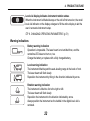
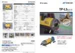
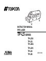
INSTRUCTION MANUAL PIPE LASER TP-L5 SERIES TP-L5GV TP-L5G TP-L5BG TP-L5AV TP-L5A TP-L5B 32956 90092 HOW TO READ THIS MANUAL Thank you for selecting the TOPCON instrument. • Please read this instruction manual carefully before using this instrument. • Verify that all equipment is included. “ STANDARD SYSTEM COMPONENTS” (p. iii) • The specifications and general appearance of the instrument are subject to change without prior notice and without obligation by Topcon Corporation and may differ from those appearing in this manual. • Some of the diagrams shown in this manual may be simplified for easier understanding. Symbols The following conventions are used in this manual. : Indicates precautions and important items which should be read before operations. : Indicates the chapter title to refer to for additional information. : Indicates supplementary explanation. i HOW TO READ THIS MANUAL Notes regarding manual style • Except where stated, "TP-L5" means TP-L5GV/G/BG/AV/A/B in this manual. • The specifications by the model are as follows. Model Laser Upper/Lower Laser Green --- Centerline LED --- TP-L5GV TP-L5G --- TP-L5BG ----- TP-L5AV TP-L5A TP-L5B Auto alignment " Automatic alignment with the target (TP-L5GV/G/AV/A only)" (p. 39) Red ----- --- • All company and product names featured in this manual are trademarks or registered trademarks of each respective organization. ii STANDARD SYSTEM COMPONENTS 1) 2) 3) 4) 5) 6) Pipe Laser TP-L5..................................... 1pc. Remote controller RC-200....................... 1pc. Battery BT-53Q (rechargeable battery) ... 1pc. AC/DC Converter AD-13 ......................... 1pc. Battery adapter BA-2 ............................... 1pc. Self-centering Feet ø150mm .................................................. 4pcs. ø200mm .................................................. 4pcs. ø250mm .................................................. 4pcs. ø300mm .................................................. 4pcs. 7) Single point foot....................................... 1pc. 8) Target....................................................... 1set 9) AAA Manganese battery*1) ...................... 4pcs. 10) Carrying case .......................................... 1pc. 11) Instruction manual ................................... 1vol. • Please make sure that all of above items are in the box when you unpack. *1) Batteries included in the package are to confirm the initial operation. Please replace the batteries provided with new batteries (alkaline) as soon as possible. iii CONTENTS 1. 2. 3. 4. PRECAUTIONS FOR SAFE OPERATION ............................................................................ 1 PRECAUTIONS ..................................................................................................................... 7 LASER SAFETY INFORMATION ........................................................................................ 13 PRODUCT OUTLINE ........................................................................................................... 16 4.1 Parts and Functions of the Instrument.......................................................................... 16 Control panel............................................................................................................. 18 Key Operation (When the instrument is locked) ....................................................... 21 Indicators .................................................................................................................. 22 5. USING THE BATTERY ........................................................................................................ 25 5.1 Battery BT-53Q (Rechargeable battery) ....................................................................... 25 Removing the battery................................................................................................ 25 Battery charging........................................................................................................ 26 5.2 Battery Holder DB-53 (Dry battery holder) *Optional accessory................................... 29 Removing the battery................................................................................................ 29 Replacing the dry cell batteries................................................................................. 29 5.3 PC-17 (Power cable for 12vDC) *Optional accessory .................................................. 30 6. BASIC OPERATION ............................................................................................................ 31 6.1 Setting up the Instrument.............................................................................................. 31 6.2 Grade setting procedure ............................................................................................... 32 Direct entry of grade value........................................................................................ 32 Set grade value by moving laser............................................................................... 35 iv CONTENTS 6.3 Setting Laser Line ......................................................................................................... 36 Automatic Centering.................................................................................................. 38 Automatic alignment with the target (TP-L5GV/G/AV/A only) ................................... 39 6.4 Changing the laser beam mode.................................................................................... 42 7. STANDARD ACCESSORIES............................................................................................... 43 7.1 Self-centering Feet........................................................................................................ 43 7.2 Single Point Foot........................................................................................................... 44 7.3 Remote Controller (RC-200) ......................................................................................... 45 Replacing battery for Remote Control, RC-200 ........................................................ 49 7.4 Target ........................................................................................................................... 50 8. CHANGING OPERATING PARAMETERS .......................................................................... 51 8.1 Operating Parameters................................................................................................... 51 8.2 How To Change Operating Parameters........................................................................ 53 8.3 How to Input (Change) Security Code .......................................................................... 55 8.4 How to change Company Name ................................................................................... 60 9. CHECKS AND ADJUSTMENTS .......................................................................................... 66 9.1 Procedure To Check and Adjust Laser Calibration....................................................... 66 Checking Calibration ................................................................................................. 66 Adjusting Calibration ................................................................................................. 67 9.2 Checking of Upper/Lower Laser (TP-L5GV/AV only).................................................... 70 v CONTENTS 10. 11. 12. 13. 14. ERROR DISPLAYS.............................................................................................................. 71 TROUBLESHOOTING ......................................................................................................... 72 OPTIONAL ACCESSORIES ................................................................................................ 77 SPECIFICATIONS ............................................................................................................... 78 REGULATIONS.................................................................................................................... 81 vi 1. PRECAUTIONS FOR SAFE OPERATION For the safe use of the product and prevention of injury to operators and other persons as well as prevention of property damage, items which should be observed are indicated by an exclamation point within a triangle used with WARNING and CAUTION statements in this instruction manual. The definitions of the indications are listed below. Be sure you understand them before reading the manual’s main text. Definition of Indication WARNING Ignoring this indication and making an operation error could possibly result in death or serious injury to the operator. CAUTION Ignoring this indication and making an operation error could possibly result in personal injury or property damage. This symbol indicates items for which caution (hazard warnings inclusive) is urged. Specific details are printed in or near the symbol. This symbol indicates items which are prohibited. Specific details are printed in or near the symbol. This symbol indicates items which must always be performed. Specific details are printed in or near the symbol. 1 1. PRECAUTIONS FOR SAFE OPERATION General Warning Do not use the unit in areas exposed to high amounts of dust or ash, in areas where there is inadequate ventilation, or near combustible materials. An explosion could occur. Do not perform disassembly or rebuilding. Fire, electric shock, burns or hazardous radiation exposure could result. Do not use under thunderous weather conditions. This unit is conductive and if struck by lightning, death or injury could result. Handle with care when using near high voltage cables or transformers. This unit is conductive and contact could result in electric shock. When securing the instrument in the carrying case make sure that all catches, including the side catches, are closed. Failure to do so could result in the instrument falling out while being carried, causing injury. 2 1. PRECAUTIONS FOR SAFE OPERATION Caution Do not use the carrying case as a footstool. The case is slippery and unstable so a person could slip and fall off it. Do not place the instrument in a case with a damaged case or belt. The case or instrument could be dropped and cause injury. Do not wield or throw the plumb bob. A person could be injured if struck. Power Supply Warning Do not short circuit. Heat or ignition could result. Do not place articles such as clothing on the battery charger while charging batteries. Sparks could be induced, leading to fire. Do not use voltage other than the specified power supply voltage. Fire or electrical shock could result. 3 1. PRECAUTIONS FOR SAFE OPERATION Do not use batteries other than those designated. An explosion could occur, or abnormal heat generated, leading to fire. Do not use damaged power cords, plugs or loose outlets. Fire or electric shock could result. Do not use power cords other than those designated. Fire could result. Use only the specified battery charger to recharge batteries. Other chargers may be of different voltage rating or polarity, causing sparking which could lead to fire or burns. Do not use the battery or charger for any other equipment or purpose. Fire or burns caused by ignition could result. Do not heat or throw batteries or chargers into fire. An explosion could occur, resulting in injury. To prevent shorting of the battery in storage, apply insulating tape or equivalent to the terminals. Otherwise shorting could occur, resulting in fire or burns. 4 1. PRECAUTIONS FOR SAFE OPERATION Do not use batteries or the battery charger if wet. Resultant shorting could lead to fire or burns. Do not connect or disconnect power supply plugs with wet hands. Electric shock could result. Caution Do not touch liquid leaking from batteries. Harmful chemicals could cause burns or blisters. Tripod Caution When mounting the instrument to the tripod, tighten the centering screw securely. Failure to tighten the screw properly could result in the instrument falling off the tripod, causing injury. Tighten securely the leg fixing screws of the tripod on which the instrument is mounted. Failure to tighten the screws could result in the tripod collapsing, causing injury. 5 1. PRECAUTIONS FOR SAFE OPERATION Do not carry the tripod with the tripod shoes pointed at other persons. A person could be injured if struck by the tripod shoes. Keep hands and feet away from the tripod shoes when fixing the tripod in the ground. A hand or foot stab wound could result. Tighten the leg fixing screws securely before carrying the tripod. Failure to tighten the screws could lead to the tripod legs extending, causing injury. 6 2. PRECAUTIONS Before starting work or operation, be sure to check that the instrument is functioning correctly with normal performance. Charging Battery • Be sure to charge the battery within the charging temperature range. Charging temperature range: 10 to 35°C Warranty policy for Battery • Battery is an expendable item. The decline in retained capacity depending on the repeated charging/discharging cycle is out of warranty. Vibration and Impact Protection • When transporting the instrument, provide protection to minimize risk of severe vibration or impact. Severe vibration or impacts may affect beam accuracy. Sudden changes of temperature • A sudden change in temperature may cause water condensation on the glass used for the laser emission part. In such a case, let the instrument stand for a while to allow it to adjust to the temperature prior to actual use. 7 2. PRECAUTIONS Storage precautions • When storing the instrument, keep it in a place not exposed to direct sunlight and at the temperature range from -30 to 60°C. • Do not store the wet instrument in the carrying case. If any part of the instrument is wet, thoroughly wipe off with soft cloth and leave it dry before storing in the carrying case. Battery • The battery is not charged when the instrument is shipped. Make sure to charge it fully before use. • If the battery is over-discharged, it may make re-charging impossible or shorten the running time. Store the battery when it is fully charged. • Even if the instrument is not used for a long period, charge the battery at least once per 3 to 6 months to maintain the performance of the battery. • If the battery's running time shortens after using it for a certain period, contact your local dealer. • When using an external power supply, it should be rated between 9 and 20 volts DC. 8 2. PRECAUTIONS Measurement This instrument is designed for survey and survey related uses (that is, surveying coordinates, distance, angles and depths, and recording such measurements). This product should never be used: • Without the user thoroughly understanding this manual. • After disabling safety systems or altering the product. • With unauthorized accessories. • Without proper safeguards at the survey site. • Contrary to applicable laws, rules, and regulations. Maintenance • Wipe off moisture completely if the instrument gets wet during survey work. • Wipe away stain or dirt with soft cloth after dusting. • Clean storage case using cloth moistened with neutral detergent or water. Do not use ether, benzene, thinner or other solvents. • To clean the instrument or the carrying case, lightly moisten a soft cloth in a mild detergent solution. Wring out excess water until the cloth is slightly damp, then carefully wipe the surface of the unit. Do not use any alkaline cleaning solutions, alcohol, or any other organic solvents on the instrument or display. • When removing the instrument from the carrying case, never pull it out by force. The empty carrying case should be closed to protect it from moisture. • Check the tripod for loose fit and loose screws. • Check the instrument for proper adjustment periodically to maintain the instrument accuracy. 9 2. PRECAUTIONS Other precautions • Protect the instrument from heavy shocks or vibration. • When setting up the instrument, position it so the bubble in the digital level vial on the display is in the center position. • When you remove the instrument from the carrying case, be sure to open the cover of the case after laying the case down, right side up. • Consult your local dealer before using the instrument under special conditions such as long periods of continuous use or high levels of humidity. In general, special conditions are treated as being outside the scope of the product warranty. • Physical reflection and refraction may occur under hot weather conditions or in a small pipe diameter due to its temperature or moisture conditions, which could interfere with the precision or available range of the instrument. To minimize the effect of these conditions please take the following precautions. 1) Place the pipe hot side (heated by sunlight etc.) down. 2) Do not apply an excessive amount of "pipe adhesive" to the pipe joints. 3) Immediately back fill the trench as pipe work is finished. If it is difficult to follow the instructions noted above, please use a blower (commerciallyavailable) or place the instrument on the pipe before performing the operation. User • Wear the required protectors (safety shoes, helmet, etc.) when operating. 10 2. PRECAUTIONS Exporting this product (Relating EAR) • This product is equipped with the parts/units, and contains software/technology, which are subject to the EAR (Export Administration Regulations). Depending on countries you wish to export or bring the product to, a US export license may be required. In such a case, it is your responsibility to obtain the license. The countries requiring the license as of May 2013 are shown below. Please consult the Export Administration Regulations as they are subject to change. North Korea Iran Syria Sudan Cuba URL for the EAR of the US: http://www.bis.doc.gov/policiesandregulations/ear/index.htm Exceptions from Responsibility • The user of this product is expected to follow all operating instructions and make periodic checks of the product’s performance. • The manufacturer, or its representatives, assumes no responsibility for results of a faulty or intentional usage or misuse including any direct, indirect, consequential damage, and loss of profits. 11 2. PRECAUTIONS • The manufacturer, or its representatives, assumes no responsibility for consequential damage, and loss of profits by any disaster, (an earthquake, storms, floods etc.). A fire, accident, or an act of a third party and/or a usage any other usual conditions. • The manufacturer, or its representatives, assumes no responsibility for any damage, and loss of profits due to a change of data, loss of data, an interruption of business etc., caused by using the product or an unusable product. • The manufacturer, or its representatives, assumes no responsibility for any damage, and loss of profits caused by usage except for explained in the user manual. • The manufacturer, or its representatives, assumes no responsibility for damage caused by wrong movement, or action due to connecting with other products. 12 3. LASER SAFETY INFORMATION The TP-L5 is classified as a class 3R Laser Product according to IEC Standard Publication 60825-1 Ed.2.0: 2007 and United States Government Code of Federal Regulation FDA CDRH 21CFR Part 1040.10 and 1040.11 (Complies with FDA performance standards for laser products except for deviations pursuant to Laser Notice No.50, dated June 24, 2007.) TP-L5GV/AV TP-L5G/BG/A/B Warning Label Laser beam emitted from here (TP-L5GV/AV model only) TP-L5AV/A/B Laser beam emitted from here Laser beam emitted from here (TP-L5GV/AV model only) TP-L5GV/G/BG 13 3. LASER SAFETY INFORMATION Warning • Use of controls or adjustments or performance of procedures other than those specified herein may result in hazardous radiation exposure. • Never intentionally point the laser beam at another person. The laser beam is injurious to the eyes and skin. If an eye injury is caused by exposure to the laser beam, seek immediate medical attention from a licensed ophthalmologist. • The laser beam is emitted when the power is turned ON. Before turning the power on, make sure that persons are not located in the path of the laser beam. • Secure the instrument in a fixed position before it is used. If it is necessary to hold the instrument by hand, make sure that persons are not located in the area before the laser is emitted. • Do not look directly into the laser beam. Doing so could cause permanent eye damage. • Do not stare at the laser beam. Doing so could cause permanent eye damage. • Never look at the laser beam through a telescope, binoculars or other optical instruments. Doing so could cause permanent eye damage. Caution • Perform checks at start of work and periodic checks and adjustments with the laser beam emitted under normal conditions. 14 3. LASER SAFETY INFORMATION • When the instrument is not being used, turn off the power. • When disposing of the instrument, destroy the battery connector so that the laser beam cannot be emitted. • Avoid setting the instrument at heights at which the path of the laser may strike pedestrians or drivers at head height. Operate the instrument with due caution to avoid injuries that may be caused by the laser beam unintentionally striking a person in the eye. • Do not emit the laserbeam at eye level. • Never point the laser beam at mirrors, windows or surfaces that are highly reflective. The reflected laser beam could cause serious injury • Only those who have received training as per the following items shall use this product. • Read this manual for usage procedures for this product. • Hazardous protection procedures (read "LASER SAFETY INFORMATION") • Requisite protective gear (read "LASER SAFETY INFORMATION") • Accident reporting procedures (stipulate procedures beforehand for transporting the injured and contacting physicians in case there are laser-induced injuries). • Persons working within the range of the laser beam are advised to wear eye protection which corresponds to the laser wavelength of the instrument being used. • Areas in which the laser is used should be posted with a standard laser warning sign. • Sight targets so that the laser beam does not stray from them. 15 4. PRODUCT OUTLINE 4.1 Parts and Functions of the Instrument Remote control receiving window Battery knob Battery Operating keys Upper laser emitting window (TP-L5GV/AV only) Display Handle Lower laser emitting window Power supply connector (with cap) (TP-L5GV/AV only) Handle fixing screw 16 4. PRODUCT OUTLINE Upper laser blocking hatch (TP-L5GV/AV only) Blocks the upper laser beam by rotating Remote control receiving window Laser beam window Laser beam emitted from here Grade axis mark Laser grade starting point Centerline LED (TP-L5G/BG/A/B only) Laser centerline mark (TP-L5G/BG/A/B only) Starting point of the laser line 17 4. PRODUCT OUTLINE Control panel Lock key Warning/Standby Indicator LED Beam mode key Centerline LED (TP-L5G/BG/A/B)/ LD (TP-L5GV/AV) key Auto alignment key (TP-L5GV/G/AV/A only) Laser right/left key (Line control/Digits shifting/ Auto centering) Laser right/left key (Line control/Digit shifting/ Auto centering) Power key Setting key Laser up/down key (Value setting) The illumination of the display will be ON for 30 seconds whenever anyone key is pressed. 18 4. PRODUCT OUTLINE Key/LED Nomenclature Centerline LED / LD (GV/AV) key Function Turn the centerline LED/LD (GV/AV) ON or OFF by pressing. (Auto shut off after 30 minutes.) Beam mode key The mode of laser beam is switched alternately. "On mode" / "Blinking mode" / "Energy mode (TP-L5GV/G/ BG only)" “6.4 Changing the laser beam mode” (p.42) Lock key Forbids the entry of the laser up/down key, the laser right/ left key, the setting key and the auto alignment key of the instrument and the remote control, as well as prevents the setting value to be changed by incorrect operation. Pressing again releases this function. “Key Operation (When the instrument is locked)” (p.21) Auto alignment key (TP-L5GV/G/AV/A) The laser beam is aligned to the center of the target automatically. “Automatic alignment with the target (TP-L5GV/G/AV/ A only)” (p.39) 19 4. PRODUCT OUTLINE Key/LED Nomenclature Laser right/left key Function Press to move the laser beam to the right or to the left. Active indicating digit shifts to the right or the left. “6.3 Setting Laser Line” (p.36) By pressing both keys at the same time, the laser beam returns to the center automatically. “Automatic Centering” (p.38) Laser up/down key Press to move the laser beam up or down. Positive and negative values are indicated in the display for grade setting. By pressing both keys at the same time, returns grade to 00.000% (0‰). Setting key Press to enter grade shown on display. Power key Turn the instrument ON or OFF. Warning / Standby Indicator LED Flashes to indicate warning or standby mode. 20 4. PRODUCT OUTLINE Key Operation (When the instrument is locked) When the instrument is locked, the operable/inoperable keys of the instrument and the remote control are as follows. RC-200 TP-L5 Centerline LED/LD key Operable keys Operable keys Beam mode key Power key Inoperable keys Auto alignment key Inoperable keys Laser ON/OFF switch Laser beam mode key Auto alignment key Laser right/left key Laser up/down key Laser right/left key Setting key • Press the lock key on the instrument to release the lock function. 21 4. PRODUCT OUTLINE Indicators Laser line indicator Digital level vial, rotate instrument until centered Indicates the direction of the laser line. Battery warning indication Remaining battery capacity is shown in 3 steps. Power remaining for operation Centerline LED/LD (GV/AV) key Operating time is limited. Recharging or alternate power will be required soon. Charging while using 12 volt DC external battery. Grade indication Percent or Permil symbol Lock indicator Indicates when the instrument is locked. Flashing alternatory Auto leveling indication (Flashing) Flashes when the instrument is auto leveled. After auto leveling is finished, the display changes laser mode. Laser mode indication By pressing the beam mode key, the mode is switched alternately. “6.4 Changing the laser beam mode” (p.42) 22 4. PRODUCT OUTLINE Level vial display indicates instrument rotation status When the instrument is titled sideways or the unit is first turned on, the small level vial indicator on the display enlarges to fill the entire display to aid the user in accurate instrument setup. “8. CHANGING OPERATING PARAMETERS” (p.51) Warning indications Battery warning indication Operation is impossible. The laser beam is not emitted then, and the centerline LED does not turn on, too. Charge the battery or replace with a fully charged battery. Level warning indication The instrument tilted beyond the auto-leveling range to the back or front. The laser beam will flash slowly. Reposition the instrument by tilting in the direction indicated by arrow. Rotation warning indication The instrument is tilted too far to the right or left. The laser beam will flash slowly. Reposition the instrument to the direction indicated by arrow. Always position the instrument so the bubble in the digital level vial is centered. 23 4. PRODUCT OUTLINE Rotation direction detection error Reposition the instrument horizontally. WAIT During laser position adjusting process The display will appear during the adjustment of the laser after the startup of the instrument. Operations can be performed just after "WAIT" disappears. • If the battery is removed while the instrument is turned ON, this display may be appeared the next time the instrument starts up. • This display may be appeared when operating at especially high/low temperature or starting up the instrument after the battery warning indication "EMPTY" being displayed. • While "WAIT" is displayed, the key operations are impossible. Safety Lock If the instrument is moved for any reason after the laser is OFF (standby mode) using the remote controller, a safety lock will be in operation. This is to insure operational accuracy. "SAFETY LOCK" will appear on the display and the laser beam and the indicator LED will flash. To reset, turn power OFF the instrument by the Power key on the control panel, check the instrument position, and then turn ON the instrument again. While the safety lock is in operation, power cannot be turned ON/OFF by the remote controller. 24 5. USING THE BATTERY • The battery was not charged at the factory. Charge the battery fully before using the instrument. 5.1 Battery BT-53Q (Rechargeable battery) Removing the battery • Before removing the battery, turn off the power to the instrument. 1 Turn the battery knob to "OPEN", lift and remove the BT-53Q rechargeable battery. 25 5. USING THE BATTERY Battery charging 1 Insert the BA-2 battery adapter into the Battery adapter BA-2 BT-53Q rechargeable battery as shown. 2 Plug the AC/DC converter AD-13 into the BA-2. 3 Insert the AC/DC converter power cord into the appropriate AC outlet. BT-53Q LED of the BT-53Q rechargeable battery will light up red. 4 After charging is complete (Charging time: Approx. 9 hours), unplug the BA-2 battery adapter from the BT-53Q rechargeable battery. The LED will light up green. 5 Unplug the AC/DC converter power cord from the AC receptacle. 26 AC/DC converter AD-13 5. USING THE BATTERY • Charging while operating from DC12V external battery This function is useful when operating from the BT-53Q rechargeable battery that is low and needs charging. Using the instrument with 12vDC external battery in ambient temperature [10 to 35°C (50 to 95°F)], the rechargeable battery can be recharged while the instrument is in use. Optional accessory power cable (PC-17) is necessary to use the instrument with 12vDC external battery. “5.3 PC-17 (Power cable for 12vDC) *Optional accessory” (p.30) Connect 12vDC external battery and turn the instrument ON, the BT-53Q will charge automatically. The charging indicator LED on top of the BT-53Q will indicate charging status. • The LED on the battery indicates charging status as follows: Red ON : Green ON : Green flashing : Red flashing : Charging Charging completed. Internal error of BT-53Q rechargeable battery BT-53Q rechargeable battery protection feature* is working automatically. The instrument can be used in this case. *Automatic protection feature: In case of overcharge or high or low ambient temperatures that exceeds charging temperature range, charging will be stopped or changed to protect battery. 27 5. USING THE BATTERY • If the 12vDC external battery is disconnected while working, the power source will automatically switch to the BT-53Q rechargeable battery. • Be sure to charge the battery within the charging temperature range (10 to 35°C). • Do not perform charging with others except the AC/DC converter AD-13. • For l.onger battery life, conform to the suggested charging time to the extent possible. • The battery source will discharge when stored and should be checked before using with instrument. • Do not recharge the battery when fully charged. Doing so will lower battery performance. • For long-term storage, the battery should be charged at least once per 3 to 6 months and store in a place at 30°C or below. If you allow the battery to become completely discharged, it will have an effect on future charging. • Batteries generate power using a chemical reaction and as a result have a limited lifetime. Even when in storage and not used for long periods, battery capacity deteriorates with the passage of time. This may result in the operating time of the battery shortening despite having been charged correctly. In this event, a new battery is required. 28 5. USING THE BATTERY 5.2 Battery Holder DB-53 (Dry battery holder) *Optional accessory Removing the battery 1 Turn the battery knob to "OPEN", lift and remove the battery holder DB-53. Replacing the dry cell batteries 1 Open battery holder DB-53 by turning the lid knob to "OPEN". 2 Remove the old batteries and replace with new batteries (4xD size dry cell batteries) matching [+] and [-] as shown in the figure. Close the battery cover by turning the knob to "LOCK". DB-53 3 Insert the battery holder into the instrument. Secure by turning the knob to "LOCK". • Replace all 4 batteries with new ones at the same time. • Insert the batteries in the battery box according to the appointed direction. • Do not mix used and new batteries, and do not mix different types of batteries together. 29 5. USING THE BATTERY 5.3 PC-17 (Power cable for 12vDC) *Optional accessory Red clip to positive terminal PC-17 Power cable for 12vDC Black clip to negative terminal 12 volt DC battery • Stop the engine while using automobile battery. • Be sure to connect the red clip to positive terminal and black clip to negative terminal of the battery when using the Power source cable for 12 volt DC. (Electric current consumption: Max. 3A) • Always turn OFF the instrument before removing on-board battery or external power cable. 30 6. BASIC OPERATION 6.1 Setting up the Instrument 1 Always position the instrument so the bubble in the digital level vial is centered. • The laser might move from side to side in order to adjust the position of laser beam after the instrument is turned ON (See WAIT display on p.24). The instrument is not operable during this adjusting process (for about 30 seconds). The instrument has a self-leveling range of ±10%. To assure proper self-leveling the instrument must be positioned to within 10% of the grade entered. +10% (+100)‰ -10% (-100)‰ Setting grade Inclination of the instrument • A warning indication will appear depending on the instrument's installed condition. "Warning indications" (p.23 to 24) 31 6. BASIC OPERATION 6.2 Grade setting procedure Direct entry of grade value (Example) Setting grade of -12.345% (Format ± AB.CDE%) • Input range: -15.000 to 40.000% (-150.00 to 400.00‰) • Setting grade is not possible when the instrument is locked. Procedure Key operation 1 Press [SET] key. The previous data will be shown, and ± mark is highlighted. 2 Press [ ] or [ ] key to change the sign or to -. 32 Display 6. BASIC OPERATION 3 Press [ ] key to shift to digit A. Disit A is highlighted. 4 Press [ ] or [ ] key to change value to or "1". 5 Press [ ] key to shift to digit B. Disit B is highlighted. 6 Press [ ] or [ ] key to change value to or "2". 7 Repeat previous steps to change values ・ ・ ・ ・ ・ of digit C to "3", digit D to "4" and digit E to "5". 33 6. BASIC OPERATION 8 Press [SET] key. After entering, the instrument starts repositioning the laser to the grade. The auto leveling indication blinks during the grade setting process. The laser beam blinks at the same time. • The grade value displayed on the screen will be set automatically if no value is entered within 15 seconds. 34 6. BASIC OPERATION Set grade value by moving laser Grade value can be set directly by moving laser up or down. Be sure that the lock is disengaged before operating. The grade display will increase or decrease according to the direction of the laser. Pressing the [ ] or [ ] key, the laser beam moves up or down. • 0 setting Pressing the [ ] and [ 00.000% (0‰). ] key at the same time, the display and the laser will return to 35 6. BASIC OPERATION 6.3 Setting Laser Line Use the laser right/left key on the instrument display panel or the RC-200 remote control to move the horizontal laser position to the left or right required. The maximum adjusting range is 9 m (29.5 ft.) at a distance of 30 m (100ft.) The speed of the line travel is variable. When the key is first pressed, the speed will be slow. By pressing the key continuously, the speed of line travel will increase. The relative position of the laser beam is shown on the display as indicated below. • Setting Laser Line is not possible when the instrument is locked. This display indicates that the laser line is positioned at the left end of the adjustment range. The laser line will not travel to the left even if the laser right/left key is held down. In addition, the laser will blink to alert the user of this condition. It is always a good idea to pre-position the laser to the center of its adjusting range prior to setup. LASER LINE INDICATOR 36 This display indicates that the laser line is positioned at the right end of the adjustment range. The laser line will not travel to the right even if the laser right/left key is held down. In addition, the laser will blink to alert the user of this condition. It is always a good idea to pre-position the laser to the center of its adjusting range prior to setup. 6. BASIC OPERATION Maximum line adjust range 37 6. BASIC OPERATION Automatic Centering Press both laser right and left keys at the same time. The laser will return to the center of the line adjustment range automatically. ・ Automatic centering is not possible when the instrument is locked. Laser line indication Press the [ 38 ] and [ ] key at the same time. 6. BASIC OPERATION Automatic alignment with the target (TP-L5GV/G/AV/A only) When the alignment is placed on centerline so it is in the alignment path of the beam, the laser will search the horizontal center of the target and automatically align the beam to it. Set the alignment target as follows and press the automatic alignment key on the instrument or the RC200 remote control. The instrument starts automatic alignment and the following display is shown. • This function is helpful for second day set ups. ・ Automatic alignment is not possible when the instrument is locked. Detection strips Laser receiving side 39 Automatic alignment key 6. BASIC OPERATION Target Set the target so the detection strips face the front of the instrument. • Large atmospheric motions could shorten the range of use of automatic alignment. To prevent atmospheric motions from occurring, limit the working range within the shade or use a blower (commercially-available) for working. • When using the RC-200 remote control at close range during auto alignment mode, the laser may be subject to stop outside the target. Press the automatic alignment key to start automatic alignment again. 40 6. BASIC OPERATION Display WAIT The display shows auto leveling is in process. After auto leveling is completed, automatic alignment starts. The display shows auto alignment is in process. Each step shows alignment progress. Automatic alignment in progress Automatic alignment will finish soon. Alignment is completed. Confirm the laser beam on the target. If necessary, use the laser right/left key or the remote control RC-200 and align the laser precisely. Alignment target is lost during auto alignment mode. Reset the instrument and press the automatic alignment key again. 41 6. BASIC OPERATION 6.4 Changing the laser beam mode Two laser beam modes are available, ON and Blinking. A third mode, Energy-saving, is available on green laser beam models. By pressing the beam mode key, the beam mode will change alternatively. Press the beam mode key. TP-L5AV/A/B TP-L5GV/G/BG Display Display ON mode Blinking mode ON mode Blinking mode Energy-saving mode 42 7. STANDARD ACCESSORIES 7.1 Self-centering Feet Four sets of centering feet are provided with the TP-L5. The feet provided with TP-L5 will center the laser beam inside the following diameters of pipe: 150mm (6"), 200mm (8"), 250mm (10") and 300mm (12") They can also be used to set laser on top of the pipe or on a flat surface. 150mm / 6" 200mm / 8" Single point foot 250mm / 10" 300mm / 12" 43 7. STANDARD ACCESSORIES 7.2 Single Point Foot Use the single pointed foot when the TP-L5 is unstable due to setting up on rough surfaces. It is possible to use two self-centering feet for 200 mm (8") diameter with the single point foot when the surface is level. 44 7. STANDARD ACCESSORIES 7.3 Remote Controller (RC-200) The RC-200 allows you to remotely control most function of the TP-L5 as shown below. The RC-200 is convenient for aligning the beam while using a transit, or for saving power by temporarily putting the unit in standby mode using the ON/OFF switch. Signal aperture Signal lamp Automatic alignment mode key When red LED is blinking, the signal is transmitting Automatic centering Press both keys at the same time Laser right/left key Laser right/left key Laser ON/OFF switch Laser beam mode key Controls laser ON/OFF for the instrument 45 7. STANDARD ACCESSORIES • Operating range by remote control: Approx.200 m (656 ft.) (Though the pipe from a forward position) Approx.25 m (82 ft.) (From above panel) • The laser ON/OFF switch controls the laser beam only, not for the instrument. To turn power OFF to the instrument, be sure to switch OFF the instrument after operation is finished. When the laser is turned off by the laser ON/OFF switch, "STANDBY" is indicated on the display and the laser flashes once for five seconds (standby mode). • To turn the laser beam ON again after the laser is turned off by the remote control, wait for 2 seconds or more and then press the laser ON/OFF switch for 2 seconds or more. • Large atmospheric motions could shorten the operating range by the remote control. To prevent atmospheric motions from occurring, limit the working range within the shade or use a blower (commercially-available) for working. 46 7. STANDARD ACCESSORIES • When using the remote controller, direct the signal aperture to the remote control receiving window on front of the TP-L5. Remote control receiving window (Laser beam can be received from above panel.) Remote control receiving window Laser line will travel in the opposite direction of the laser right/left key when using the remote control from a forward position. Laser line will travel in the direction of the laser right/left key when using the remote control from above or behind the panel position. 47 7. STANDARD ACCESSORIES RC-200 ON OFF LASER BEAM RC-200 Signal aperture Manhole Remote control receiving window Remote control receiving window ON OFF RC-200 48 LASER BEAM RC-200 Signal aperture 7. STANDARD ACCESSORIES Replacing battery for Remote Control, RC-200 1 Lift the battery cover on the back of the remote controller RC-200 is lifted up slightly by pressing toward the direction of the mark . When the lid lifts up, take it out. 2 Replace the 4 old AAA alkaline batteries with new ones. 3 Click to close the lid by pressing on it. • Replace all 4 batteries with new ones at the same time. • Insert the batteries in the battery box according to the appointed direction. • Do not mix used and new batteries, and do not mix different types of batteries together. 49 7. STANDARD ACCESSORIES 7.4 Target Select the size of target assembly appropriate for the pipe diameter. Target (s) Target (L) Detection strips (TP-L5GV/G/AV/A only) Fixing screw When laser beam strikes the detection strips in auto alignment mode, the laser beam starts alignment. Level vial Target holder Laser receiving side 50 8. CHANGING OPERATING PARAMETERS 8.1 Operating Parameters The standard (default) setting for several operating parameters of the TP-L5 can be changed by the user. This table below lists the operating parameters that can be changed, the stand default setting and optional settings for each one. Functions Parameter Options [default] Description R-TILT DISPLAY DISP1 ON/ [OFF] DISP 1: default OFF ON/OFF of enlarged display (level vial indicator) When this parameter is set to ON, the level vial indicator is enlarged when the of the level vial instrument is off and the power key is first indicator pressed.The power key must be pressed again to turn instrument on. DISP2 [ON] /OFF DISP 2: default ON The level vial indicator enlarges to fill the display anytime the TP-L5 is tilted.The display returns to normal when the instrument is properly positioned or when any other control key is pressed. 51 8. CHANGING OPERATING PARAMETERS V-LED/ ON/OFF of the centerline LED/ V-LD (GV/AV) upper and lower lasers' automatic cut-off (automatic power off) UNIT Switch the unit of the grade values displayed (% / ‰) ON/OFF of Security Mode S CODE CHANGE Input / Change the Security Code S CODE --- / [30] --- : Automatic cut-off is disabled. LED/LD remains on whenever after being turned on by user. 30 : Default setting. Centerline LED/LD automatically cuts off 30 minutes after it has been turned on by user. p.19 % /‰ ON / [OFF] (no preset code) % : Default setting. Grade is displayed to the nearest thousandths of a percent (+01.235%) ‰ : Grade is displayed as per mill [+01.235% (percent) equals +012.35 (per mill)] Activates security code function. Default is OFF. Changing to ON requires the entry of a 4-digit security to turn on instrument. Allows user to input any 4-digit security code after S CODE is set to ON. Change the CHANGE NAME Allows user to enter name that will display (TOPCON preset) during powerup. Default name is TOPCON. Company Name 52 8. CHANGING OPERATING PARAMETERS 8.2 How To Change Operating Parameters EXAMPLE Change R-TILT DISPLAY, DISP1 from OFF to ON and disable the V-LED/LD (TP-L5GV/AV) automatic cut-off. Procedure Key operation 1 Press Power ON key while pressing and holding the Lock key. The R-TILT DISPLAY is the first parameter setting. Power ON [ R-TILT DISPLAY ] V-LD*1 - - - [ 30 ] PARAMETERS DISP1 ON [ OFF ] DISP2 [ ON] OFF DISPLAY. 3 The DISP1 parameter highlights to show it is active. Press [ select [ON] for DISP1. PARAMETERS + 2 Press SET key to select R-TILT Display PARAMETERS DISP1 [ ON] OFF DISP2 [ ON] OFF ] key to 53 8. CHANGING OPERATING PARAMETERS 4 Press SET key to accept new setting. PARAMETERS R-TILT DISPLAY V-LD - - - [ 30 ] 5 Press [ ] key to select [---]. PARAMETERS R-TILT DISPLAY V-LD - - - [ 30 ] 6 Press SET key to accept new setting. Display will change to operating mode. The unit will now operate with the new parameter settings (level vial indicator enlarged on power-up and centerline LED always on). *1 "V-LED" is indicated when the TP-L5G/BG/A/B is used. 54 8. CHANGING OPERATING PARAMETERS 8.3 How to Input (Change) Security Code To prevent unauthorized use of the TP-L5 a four-digit security can be set. The following table describes how to activate the security mode (S CODE) and select a four-digit code. When Security mode is set, it is necessary to input the code every time power is turned on (in Normal mode, Selecting mode and Checking & Adjusting mode). • Memorize the security code and file it in a safe place. It is not possible to operate the TP-L5 without entering the code. Procedure Key operation 1 Press Power ON key while pressing and holding the Lock key.*1 (text in [brackets] indicates present setting) PARAMETERS + Power ON 2 Select "CHANGE S CODE" (If first time to set code, "INPUT S CODE" is indicated.) by pressing the [ ] key four times. 4 times 55 Display [ R-TILT DISPLAY ] V-LD*2 - - - [ 30 ] PARAMETERS S CODE ON [OFF] [CHANGE S CODE ] 8. CHANGING OPERATING PARAMETERS 3 Press SET key. *3 ENTER 01234 SECURITY 56789 CODE [_ _ _ _] SET 4 Select a numeric character by pressing the [ ], [ ], [ ], [ or ] keys. Example: 7 or 5 Press SET key. ENTER 01234 SECURITY 56789 CODE [ 7_ _ _ ] SET 6 Repeat steps 4 and 5 to set ENTER 01234 SECURITY 56789 CODE [ 7777 ] SET remaining three code numbers. Example: 7777 *4 7 Select "SET" by pressing the [ ], [ ], [ ], [ ENTER 01234 SECURITY 56789 CODE [_ _ _ _] SET or ] keys. or 56 ENTER 01234 SECURITY 56789 CODE [ 7777 ] SET 8. CHANGING OPERATING PARAMETERS 8 Press SET key. SECURITY CODE SET The display returns to menu. PARAMETERS S CODE [ ON] OFF [CHANGE S CODE] 9 Press SET key. SET *1 When security mode is ON, the security code must be input to operate. *2 "V-LED" is indicated when the TP-L5G/BG/A/B is used. 57 8. CHANGING OPERATING PARAMETERS *3 When security code has been entered, but security mode is OFF, input of current security code is necessary to change security code. *4 After all four digits are chosen and the SET key is pressed, each digit will highlight in sequence. While it is higlighting, it is possible to change the number in case of error. ON/OFF of Security Mode Procedure Key operation 1 Press Power ON key while pressing 2 and holding the Lock key. (see *1 on p.57) (text in [brackets] indicates present Select "S CODE" by pressing the [ ] key three times. PARAMETERS + Power ON 3 times 3 Select ON or OFF by pressing the [ ] or [ or ] keys. 58 Display [ R-TILT DISPLAY ] V-LD*1 - - - [ 30 ] PARAMETERS UNIT [ % ] ‰ S CODE ON [ OFF ] PARAMETERS UNIT [ % ] ‰ S CODE [ ON] OFF 8. CHANGING OPERATING PARAMETERS 4 Press SET key. 5 Enter the security code which was previously set. (see *3 on p.58) CHECK 01234 SECURITY 56789 CODE [_ _ _ _] SET Enter Code 6 Select "SET" by pressing the [ ], [ ], [ ], [ or ] keys. or 7 Press SET key. CHECK SECURITY CODE 01234 56789 SECURITY CODE ACCEPTED The instrument returns to normal mode. 59 8. CHANGING OPERATING PARAMETERS 8.4 How to change Company Name The company name displayed during power-up can be changed. The following characters can be used: Numeric digits 0 to 9; capital letters A to Z; period; comma; apostrophe; space; opened and closed parenthesis. Maximum of 32 characters can be input (2 lines of 16 characters each). Procedure Key operation 1 Press Power ON key while pressing and holding the Lock key.*1 (text in [brackets] indicates present setting) PARAMETERS + Power ON 2 Press the down arrow key five [ ] times to scroll to CHANGE NAME. 5 times 60 Display [ R-TILT DISPLAY ] V-LD*2 - - - [ 30 ] PARAMETERS [CHANGE S CODE] [CHANGE NAME] 8. CHANGING OPERATING PARAMETERS 3 Press SET key. *3 COMPANY NAME ENTER NEW NAME 4 Select a character string by pressing the [ ] or [ or ] keys. = 5 Select a character in the character string by pressing the [ keys. Example; LASER(1) ] or [ or ] 61 _= _ _ _ _ _ _ _ _ _ _ _ _ _ 8. CHANGING OPERATING PARAMETERS 6 Press SET key. 7 Repeat procedures 4 and 6 until _ complete.*4 ______________ 8 Select "SET" by pressing the [ ] or [ or ] keys. _ ______________ 9 Press SET key. COMPANY NAME SET The display returns to menu. PARAMETERS S CODE ON [OFF] [CHANGE S CODE] 62 8. CHANGING OPERATING PARAMETERS 10 Press SET key. SET The instrument returns to normal mode. *1 When security mode is ON, the security code must be input to operate. *2 "V-LED" is indicated when the TP-L5G/BG/A/B is used. *3 When security code has been entered, but security mode is OFF, input of current security code is necessary to change security code. *4 Follow the steps below if it's necessary to correct a character during input. 63 8. CHANGING OPERATING PARAMETERS How to correct a character Procedure Key operation Display or LASOR(1) _ _ _ _ _ _ _ _ _ _ _ _ _ =_ _ _ _ _ _ _ _ 1 Select the left or right arrow by pressing the [ ] or [ ] keys. 2 Press [SET] key. The underline (cursor) moves to left or right by pressing the SET key. . . . . . LASOR(1)_ _ _ _ _ _ _ _ _ _ _ _ _ _ =_ _ _ _ _ _ _ _ LASOR(1) _______ _ _ _ _ _ _ _ =_ _ _ _ _ _ _ _ 3 Select a character string by pressing the [ ] or [ or ] keys. 64 LASOR(1) ________ _ ______________ ABCDEFGHIJ ←→ SET 8. CHANGING OPERATING PARAMETERS 4 Select a character in the character string by pressing the [ keys. ] or [ or ] 5 Press SET key. LASOR(1) ________ _ ______________ ABCDEFGHIJ ←→ SET LASER(1) _ ________ ______________ ABCDEFGHIJ ←→ SET Repeat steps 1 and 5 to correct other characters. 65 9. CHECKS AND ADJUSTMENTS 9.1 Procedure To Check and Adjust Laser Calibration +00.000% Checking Calibration 1 Make sure grade is set to 00.000% (0‰). 2 Locate control points directly beneath the laser beam 1m (3.3 ft) in front of the TP-L5 and 60m (197ft.) from the first control point (see illustration above). 3 Set up a transit or level midway between the 1st and 2nd control points. 66 9. CHECKS AND ADJUSTMENTS 4 Take elevation readings at both control points using the laser beam and the transit or level. If the distance between the readings at each point (x1 and x2) are the same, the unit does not need adjustment. If x1 and x2 are not the same, the unit requires adjustment as follows. Adjusting Calibration Procedure Key operation 1 When checking is finished, turn the power OFF. Power OFF 2 Press Power ON key while pressing and holding the SET key. + "0 SET" is displayed. 67 Display 9. CHECKS AND ADJUSTMENTS 3 Press SET key. "INIT" is displayed, and then "LEVELING" is displayed. INIT LEVELING 4 Adjust the height of laser beam x1 and X2 measurements are equal (use [ ] or [ ] key). LEVEL • The display will be changed to "LEVELING" again if the instrument is moved. In this case, wait until the display changes to "LEVEL" and readjust the instrument. or 68 9. CHECKS AND ADJUSTMENTS 5 Press SET key after completing the adjustment. WAIT "WAIT" is displayed. 6 When +00000 appears on the display, press the SET key again. END Repeat checking procedure above to confirm accurate calibration. • If the adjustment range is exceeded, "E72" (error) will be displayed in step 5. Repeat checking and adjusting procedure. If the error continues, contact your local dealer. 69 9. CHECKS AND ADJUSTMENTS 9.2 Checking of Upper/Lower Laser (TP-L5GV/AV only) 1 Set up the instrument on a single control point using the downward laser plummet. Target Gap 2 Set up a target approximately 3m Gap Vertical direction (10ft.) above the instrument. Laser 3 Move the target above the manhole unit the upper laser is aligned to the center of the target. Manhole 4 Rotate the instrument 180° without changing lower laser line position. Control point If the upper laser emitting position does not change more than 4mm, the unit is within specification. • If the unit is out by more than 4mm (0.014’), please contact your local dealer. 70 Laser 10. ERROR DISPLAYS If an error is displayed, follow the procedures shown below. Error Code Contents Countermeasure E-02 E-03 Abnormal operation of internal measuring system. Switch OFF the power, then ON again. Excessive vibration around the laser may cause this error. Eliminate vibration. E-04 The angle is not measured properly. Contact your local dealer. E-05 The laser's positioning is not adjusted properly. Switch OFF the power, then ON again. E-72 Indicates excessive tilt of the laser instrument during calibration checking or adjusting. Switch OFF the power, then ON again. Set the instrument level then repeat checking and adjusting calibration procedure. E-99 Abnormal operation of internal memory system detected. Switch OFF the power, then ON again. • If error code remains after trying countermeasures above, please contact your Topcon dealer. 71 11. TROUBLESHOOTING Check to see the instrument referring to the error list or the following troubleshooting list when you notice the failure of the instrument. If the instrument can't be recovered or the failure isn't written in the following list, please contact your local dealer. Conditions Causes Countermeasures Laser beam does not emit 1) Battery level is low. Laser beam blinks 1) When Level Warning Indicator blinks, the instrument is tilted beyond the self-leveling range (laser blinks slowly). 2) Any shock or vibration to the unit produces unstable condition causing beam to blink. 2) Improper connection to an external power source (such as a 12 volt DC battery). 3)The laser is turned off because the laser ON/OFF switch of the remote controller is pushed. 72 1) Recharge or replace the batteries with new ones. 2) Make sure connection is secure and attached to correct terminals. 3) Push the laser ON/OFF switch of the remote controller, then the laser is turned on. 1) Reposition the instrument until the level warning indicator disappears. 2) Eliminate the source of disturbance to the unit. 11. TROUBLESHOOTING Conditions Laser beam emits but grade setting is not possible Causes Countermeasures 1) The instrument is in lock mode. 2) The value entered is out of the grade range. 3) When Level Warning Indicator blinks, the instrument is tilted beyond the self-leveling range (laser blinks slowly). 4) Battery level is low. Laser beam emits but line setting is not possible. 1) The instrument is in lock mode. Remote control does not function. 1) The instrument is in lock mode. 2) The laser beam has reached the limit of line adjusting range. 2) The battery power of remote control is low. 73 1) Press the lock key on the instrument to release the lock function. 2) Grade entry must be in the range of 15 to 40%. 3) Reposition the instrument until the level warning indicator disappears. 4) Recharge or replace the batteries with new ones. 1) Press the lock key on the instrument to release the lock function. 2) Center the line adjustment and aim instrument so laser is roughly aimed at target. 1) Press the lock key on the instrument to release the lock function. 2) Replace the batteries. 11. TROUBLESHOOTING Conditions The laser beam is unstable. Causes Countermeasures 1) The laser beam is refracted due to temperature differences within the pipe. 1) When the pipe is laid, the trench must be backfilled immediately to help maintain temperature stability. 2) Use a blower (commerciallyavailable) to move air through the pipe to blend the air and remove mist or fog. • Cover the pipe to prevent heat build up inside the pipe. • Clear the mist or fog. 2) The laser beam is refracting and reflecting due to fog and/or mist. The laser position shifts over time passed. 1) The pipe may be sinking. 2) The target is not securely held. 74 1) Confirm the pipe grade setting using a level. 2) Secure the target within its holder. 11. TROUBLESHOOTING Conditions The grade setting value of the TP-L5 and the measured grade value are not equal. Causes Countermeasures 1) Incorrect grade value was entered. 1) Confirm the input value (‰ or %) and reset. 2) Adjust the laser and/or target so the bubble is centered. 2) The bubble on the bubble tube display of the instrument or the bubble on the target was not adjusted correctly. 3) The laser beam is refracted due to temperature differences within the pipe. 75 3) When the pipe is laid, the trench must be backfilled immediately to help maintain temperature stability. Use a blower (commerciallyavailable) to move air through the pipe to keep temperature 11. TROUBLESHOOTING Conditions Causes Countermeasures The charging lamp of the internal battery BT-53Q is blinking slowly when connected to the DC12V external battery. (Error blinking) 1) The charging temperature is out of range. 1) Recharging should take place in the temperature range of 10 to 35°C (50 to 95°F). 2) Continue the charging for 30 minutes. • If the lamp changes to red light up mode, the battery is normal. • If the lamp continues green blinking, battery is faulty and must be replaced. Always properly dispose old battery. 2) The battery BT-53Q is completely discharged. 76 12. OPTIONAL ACCESSORIES • AC/DC Converter AD-13 • Power cable for 12VDC PC-17 • Dry battery holder DB-53 • Drop manhole kit model 6 • Single pointed foot model 2 • Trivet stand model 3 • Trivet handle model 2 • Carrying case for trivet stand kit model 2 • Tripod adapter model 3 • Scope model 2 • Target (Large) • Over the top target • Optional accessories which are sold separately may be subject to change or be discontinued without notice. Contact your local dealer for the details. 77 13. SPECIFICATIONS TP-L5 Light source Wave length Laser power output Laser class Laser diameter Line control width Grade readout Minimum setting of grade Grade setting method Auto leveling range Slope direction Axis direction Horizontal accuracy Automatic alignment distance : Visible laser diode : 520nm (TP-L5GV/G/BG, green) 635nm (TP-L5AV/A/B, red) : 4.5mW : Class 3R : ø12mm : Approx. 17°Maximum line adjust range (p. 37) : -15 to 40%(-150 to 400‰) : 0.001% (0.01‰) : Absolute encoder : : : : ±10% Approx. ±4° ±10 arc seconds 5 to 150m (TP-L5GV/G/AV/A) 78 13. SPECIFICATIONS Upper/Lower Laser (TP-L5GV/AV only) Light source : Visible laser diode Wave length : 655nm Laser power output : 0.9mW (maximum) Compensating range : Grade setting direction Approx. ±4° Rotating direction Approx. ±2° Vertical accuracy (Rolling direction) : Upper ±1.5' Lower ±3.5' Power source : Ni-MH battery BT-53Q Working duration at 20°C (68°F) TP-L5GV/G/BG BT-53Q : about 40 hours DB-53 (optional accessory) : about 55 hours (Using alkaline manganese dry batteries) TP-L5AV/A/B BT-53Q : about 55 hours DB-53 (optional accessory) : about 80 hours (Using alkaline manganese dry batteries) • Battery using time will vary depending on environmental conditions and operations done with TP-L5 series. 79 13. SPECIFICATIONS External power source Charging time per battery Charging temperature range Operating temperature range Storage temperature range Water resistance Size Weight : 9 to 20V : about 9 hours : : : : : (Charging can take longer than the times stated above when temperatures are either especially high or low.) 10 to 35°C -20 to 50°C (-4 to 122 °F) -30 to 60°C (-22 to 140 °F) IPX8 (IEC 60529:2001) 122mmX330mm (without handle) 125mmX374mm (with rear handle) : about 3.8kg (with BT-53Q) Remote controller Model RC-200 Operating distance Functions Power supply Operating time : Though the pipe from a forward position, about 200m (656ft.) From above panel, about 25m (82ft.) : Line control, Laser beam ON/OFF, Laser beam mode, Automatic alignment mode, Line centering : Four AAA size dry batteries : about 8 months (Using alkaline manganese dry batteries) 80 14. REGULATIONS Region/ Country Directives/ Regulations Labels/Declarations FCC Compliance WARNING: Changes or modifications to this unit not expressly approved by the party responsible for compliance could void the user's authority to operate the equipment. U.S.A. FCC-Class A NOTE: This equipment has been tested and found to comply with the limits for a Class A digital device pursuant to Part 15 of the FCC Rules. These limits are designed to provide reasonable protection against harmful interference when the equipment is operated in a commercial environment. This equipment generates, uses, and can radiate radio frequency energy and, if not installed and used in accordance with the instruction manual, may cause harmful interference to radio communications. Operation of this equipment in a residential area is likely to cause harmful interference in which case the user will be required to correct the interference at his own expense. Declaration of Conformity Model Number: Trade Name: 81 TP-L5 TOPCON CORPORATION 14. REGULATIONS Manufacture Name: Address: TOPCON CORPORATION 75-1, Hasunuma-cho, Itabashi-ku, Tokyo, 174-8580 JAPAN JAPAN Country: U.S.A. Representative Responsible party: TOPCON POSITIONING SYSTEMS,INC. Address: 7400 National Drive Livermore, CA94551, U.S.A Telephone number: 925-245-8300 California, U.S.A. Proposition65 82 14. REGULATIONS Region/ Country California, and NY, U.S.A. Directives/ Regulations Labels/Declarations Recycling Batteries 83 14. REGULATIONS Canada ICES-Class A This Class A digital apparatus meets all requirements of Canadian InterferenceCausing Equipment Regulations. Cet appareil numérique de la Class A respecte toutes les exigences du Reglement sur le matériel brouilleur du Canada. This class A digital apparatus complies with Canadian ICES-003. Cet appareil numérique de la classe A est conforme a la norme NMB-003 du Canada. 84 14. REGULATIONS Region/ Country EU Directives/ Regulations Labels/Declarations EMC:Class A 85 14. REGULATIONS Region/ Country Directives/ Regulations EU WEEE Directive EU EU Battery Directive Labels/Declarations 86 http://www.topcon.co.jp Please see the attached address list or the following website for contact addresses. GLOBAL GATEWAY http://global.topcon.com/ ©2015 TOPCON CORPORATION ALL RIGHTS RESERVED