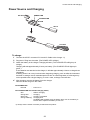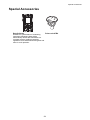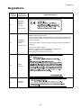
1
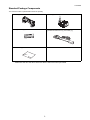
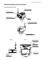
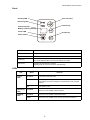
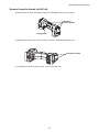
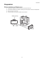
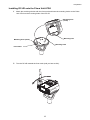
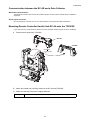
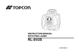
INSTRUCTION MANUAL
REMOTE CONTROL SYSTEM 4
RC-4
22210 90081
Foreword
Foreword
Thank you for purchasing the TOPCON RC-4 Remote control system-4.
For the best performance of the instrument, please read these brief instructions carefully, and
keep them in a convenient location for future reference.
This system has the following features:
• Enables wireless communications between a built-in wireless total station (TS 9 series) / imaging
station IS / Quick station QS (hereafter referred as “TS/IS/QS”) and an RC-4R on the prism side,
which allows one-man survey with the use of a data collector.
• Has the turn-round function with which more efficient one-man survey is possible.
Turn-round motions
Refer to “Light Emitting Angle” on page 16 and “Light Detecting Range” on page 17.
RC-4R should be kept aiming so that the TS/IS/QS always stays within the above range of laser beam
emission until the turn-round motions are completed.
If the aiming is out of above range while RC-4R is in turn-round motions, the turn-round could not be
completed.
XTrademark
Bluetooth® is a registered trademark of Bluetooth® SIG., Inc., U.S.A.
1
Foreword
Contents
Foreword. . . . . . . . . . . . . . . . . . . . . . . . . . . . . . . . . . . . . . . . . . . . . . . . . . . . . 1
Contents . . . . . . . . . . . . . . . . . . . . . . . . . . . . . . . . . . . . . . . . . . . . . . . . . . . . . . . . . . . . . . . . .2
Standard Package Components . . . . . . . . . . . . . . . . . . . . . . . . . . . . . . . . . . . . . . . . . . . . . . .3
Precautions for Safe Operation . . . . . . . . . . . . . . . . . . . . . . . . . . . . . . . . . . 4
TS/IS/QS series . . . . . . . . . . . . . . . . . . . . . . . . . . . . . . . . . . . . . . . . . . . . . . . . . . . . . . . . . . . .5
Precautions . . . . . . . . . . . . . . . . . . . . . . . . . . . . . . . . . . . . . . . . . . . . . . . . . . 6
Nomenclature and Functions. . . . . . . . . . . . . . . . . . . . . . . . . . . . . . . . . . . . 8
Remote Controller RC-4R . . . . . . . . . . . . . . . . . . . . . . . . . . . . . . . . . . . . . . . . . . . . . . . . . . . .8
Remote Controller Handle Unit RC-4H . . . . . . . . . . . . . . . . . . . . . . . . . . . . . . . . . . . . . . . . .10
Preparation . . . . . . . . . . . . . . . . . . . . . . . . . . . . . . . . . . . . . . . . . . . . . . . . . 11
Battery Installation and Replacement . . . . . . . . . . . . . . . . . . . . . . . . . . . . . . . . . . . . . . . . . .11
Installing RC-4R onto the Prism Unit A7R4 . . . . . . . . . . . . . . . . . . . . . . . . . . . . . . . . . . . . . .12
Communication between the RC-4R and a Data Collector . . . . . . . . . . . . . . . . . . . . . . . . . .13
Mounting Remote Controller Handle Unit RC-4H onto the TS/IS/QS . . . . . . . . . . . . . . . . . .13
Basic Operation. . . . . . . . . . . . . . . . . . . . . . . . . . . . . . . . . . . . . . . . . . . . . . 14
Power Switch ON. . . . . . . . . . . . . . . . . . . . . . . . . . . . . . . . . . . . . . . . . . . . . . . . . . . . . . . . . .14
Battery Remaining Display . . . . . . . . . . . . . . . . . . . . . . . . . . . . . . . . . . . . . . . . . . . . . . . . . .14
Battery Warning Display for RC-4R . . . . . . . . . . . . . . . . . . . . . . . . . . . . . . . . . . . . . . . . . . . .14
Battery Warning for TS/IS/QS series . . . . . . . . . . . . . . . . . . . . . . . . . . . . . . . . . . . . . . . . . . .14
Auto Power Off . . . . . . . . . . . . . . . . . . . . . . . . . . . . . . . . . . . . . . . . . . . . . . . . . . . . . . . . . . .14
Error Display . . . . . . . . . . . . . . . . . . . . . . . . . . . . . . . . . . . . . . . . . . . . . . . . . . . . . . . . . . . . .14
Setting for Communications with TS/IS/QS . . . . . . . . . . . . . . . . . . . . . . . . . . . . . . . . . . . . . .15
Light Emitting Angle. . . . . . . . . . . . . . . . . . . . . . . . . . . . . . . . . . . . . . . . . . . . . . . . . . . . . . . .16
Light Detecting Range . . . . . . . . . . . . . . . . . . . . . . . . . . . . . . . . . . . . . . . . . . . . . . . . . . . . . .17
Turn-round Function . . . . . . . . . . . . . . . . . . . . . . . . . . . . . . . . . . . . . . . . . . . . . . . . . . . . . . .18
Stopping Turn-round operations . . . . . . . . . . . . . . . . . . . . . . . . . . . . . . . . . . . . . . . . . . . . . .19
Low Power Mode of Laser Beam. . . . . . . . . . . . . . . . . . . . . . . . . . . . . . . . . . . . . . . . . . . . . .19
Reference : Turn-round motions:. . . . . . . . . . . . . . . . . . . . . . . . . . . . . . . . . . . . . . . . . . . . . .19
Setting Mode . . . . . . . . . . . . . . . . . . . . . . . . . . . . . . . . . . . . . . . . . . . . . . . . 20
Setting Items . . . . . . . . . . . . . . . . . . . . . . . . . . . . . . . . . . . . . . . . . . . . . . . . . . . . . . . . . . . . .20
How to Channel Set. . . . . . . . . . . . . . . . . . . . . . . . . . . . . . . . . . . . . . . . . . . . . . . . . . . . . . . .20
Communication Baud Rate . . . . . . . . . . . . . . . . . . . . . . . . . . . . . . . . . . . . . . . . . . . . . . . . . .21
Power Source and Charging . . . . . . . . . . . . . . . . . . . . . . . . . . . . . . . . . . .
Special Accessories . . . . . . . . . . . . . . . . . . . . . . . . . . . . . . . . . . . . . . . . . .
Regulations . . . . . . . . . . . . . . . . . . . . . . . . . . . . . . . . . . . . . . . . . . . . . . . . .
Specifications . . . . . . . . . . . . . . . . . . . . . . . . . . . . . . . . . . . . . . . . . . . . . . .
2
22
24
25
28
Foreword
Standard Package Components
The numerical value in parentheses shows the quantity.
RC-4H (1)
RC-4R (1)
Battery BT-66Q (1)
Battery charger BC-30D (1)
[AC/DC Converter AD-14(1), AC-Cable (1)]
Silicon cloth (1)
• Make sure that all of the above items are with the instrument when purchased.
3
Precautions for Safe Operation
Precautions for Safe Operation
For the safe use of the product and prevention of injury to operators and other persons as well as prevention of
property damage, items which should be observed are indicated by an exclamation point within a triangle used
with WARNING and CAUTION statements in this instruction manual.
The definitions of the indications are listed below. Be sure you understand them before reading the manual’s
main text.
Definition of Indication
WARNING
Ignoring this indication and making an operation error could possibly result in
death or serious injury to the operator.
CAUTION
Ignoring this indication and making an operation error could possibly result in
personal injury or property damage.
This symbol indicates items for which caution (hazard warnings inclusive) is urged. Specific
details are printed in or near the symbol.
This symbol indicates items which are prohibited. Specific details are printed in or near the
symbol.
This symbol indicates items which must always be performed. Specific details are printed in or
near the symbol.
General
Warning
Do not perform disassembly or rebuilding. Fire, electric shock or burns could result.
Do not use the unit in areas exposed to high amounts of dust or ash, in areas where there is
inadequate ventilation, or near combustible materials. An explosion could occur.
Risk of injury by falling down the instrument or case.
Do not use a carrying case with a damaged which belts, grips or latches.
It could be dangerous if the instrument falls over, please check that you fix the handle to the
instrument.
Power Supply
Warning
Do not short circuit. Heat or ignition could result.
Do not use voltage other than the specified power supply voltage. Fire or electrical shock could
result.
Do not use damaged power cords, plugs or loose outlets. Fire or electric shock could result.
Do not use power cords other than those designated. Fire could result.
Do not place articles such as clothing on the battery charger while charging batteries. Sparks
could be induced, leading to fire.
Use only the specified battery charger to recharge batteries. Other chargers may be of different
voltage rating or polarity, causing sparking which could lead to fire or burns.
Do not heat or throw batteries into fire. An explosion could occur, resulting in injury.
4
Precautions for Safe Operation
Do not use the battery or charger for any other equipment or purpose. Fire or burns caused by
ignition could result.
To prevent shorting of the battery in storage, apply insulating tape or equivalent to the terminals.
Otherwise shorting could occur, resulting in fire or burns.
To reduce the risk of hazards, use only CSA/UL certified power supply cord set, cord is Type SPT2 or heavier, minimum No.18 AWG copper, one end is provided with a moulded-on male
attachment plug cap (with a specified NEMA configuration), and the other end is provided with a
moulded-on female connector body (with a specified IEC non-industrial type configuration).
Do not use batteries or the battery charger if wet. Resultant shorting could lead to fire or burns.
Do not connect or disconnect power supply plugs with wet hands. Electric shock could result.
Do not use batteries other than those designated. An explosion could occur, or abnormal heat
generated, leading to fire.
Caution
Do not touch liquid leaking from batteries. Harmful chemicals could cause burns or blisters.
Bluetooth wireless technology
Warning
Do not use within the vicinity of hospitals. Malfunction of medical equipment could result.
Use the instrument at a distance of at least 22 cm from anyone with a cardiac pacemaker.
Otherwise, the pacemaker may be adversely affected by the electromagnetic waves produced
and cease to operate as normal.
Do not use onboard aircraft. The aircraft instrumentation may malfunction as a result.
Do not use within the vicinity of automatic doors, fire alarms and other devices with automatic
controls as the electromagnetic waves produced may adversely affect operation resulting in an
accident.
Laser safety
Warning
Use of controls or adjustments or performance of procedures other than those specified herein
may result in hazardous radiation exposure.
This product uses the invisible laser beam to communicate. This product is manufactured and sold in
accordance with “Performance Standards for Light-Emitting Products” (FDA/BRH 21 CFR 1040) or “Radiation
Safety of Laser Products, Equipment Classification, Requirements and User’s Guide” (IEC Publication 608251) provided on the safety standards for laser beam.
As per the said standard, this product is classified as “Class 1 (I) Laser Products”.
This is simple a product to operating that is not required to training from a “Laser safety officer”.
In case of any failure, do not disassemble the instrument. Contact TOPCON or your TOPCON dealer.
Class 1 Laser Product
Invisible Laser Beam
TS/IS/QS series
The software must be of the correct version for your version of the TS/IS/QS series, otherwise the RC-4 will not
function properly. Contact TOPCON or your TOPCON dealer for version information.
5
Precautions
Precautions
Before starting work or operation, be sure to check that the instrument is functioning correctly with normal
performance.
Battery level check
Confirm battery remaining level before operating.
Direct sunlight
Do not leave the instrument under strong sunlight for a long time. It may cause the instrument to malfunction.
Guarding the instrument against shocks
When transporting the instrument, provide some protection to minimize the risk of shocks. Heavy shocks may
cause the measurement to be faulty.
Waterproof property
The instrument can not be submerged underwater.
RC-4 is designed based on the International Standard IP65 and RC-4H is designed based on the International
Standard IP54, therefore it is protected from the normal rainfall.
Storing the instrument for long period
Remove the battery from the instrument when you would not use it for long period.
Maintenance
Always clean the instrument after use.
• If the instrument becomes wet from rain, dry moisture.
• To clean the instrument, dust off well and then wipe clean with a soft cloth.
• Remove the dust using a brush, then wipe off with a soft cloth.
For cleaning the lens surface of the receiving window, use a cleaning brush, then use a clean lintless cotton
cloth. Moisten it with alcohol (or mixture with ether) to wipe gently in a rotational motion from the center out.
• To remove the dust on the surface of emitting window or the parts made by plastic, never use thinner or
benzine. Use a clean cloth moistened with neutral detergent.
User
• This product is for professional use only!
The user is required to be a qualified surveyor or have a good knowledge of surveying, in order to understand
the user and safety instructions, before operating, inspecting or adjusting.
• Wear the required protectors (safety shoes, helmet, etc.) when operating.
Exceptions from Responsibility
• The user of this product is expected to follow all operating instructions and make periodic checks of the
product’s performance.
• The manufacturer, or its representatives, assumes no responsibility for results of a faulty or intentional usage
or misuse including any direct, indirect, consequential damage, and loss of profits.
• The manufacturer, or its representatives, assumes no responsibility for consequential damage, and loss of
profits by any disaster, (an earthquake, storms, floods etc.). A fire, accident, or an act of a third party and/or
a usage any other usual conditions.
6
Precautions
• The manufacturer, or its representatives, assumes no responsibility for any damage, and loss of profits due
to a change of data, loss of data, an interruption of business etc., caused by using the product or an unusable
product.
• The manufacturer, or its representatives, assumes no responsibility for any damage, and loss of profits
caused by usage except for explained in the user manual.
• The manufacturer, or its representatives, assumes no responsibility for damage caused by wrong movement,
or action due to connecting with other products.
7
Nomenclature and Functions
Nomenclature and Functions
Remote Controller RC-4R
Sighting collimator
Receiving window
Emitting window
(Laser beam aperture)
Panel
Antenna for SS wireless
Prism unit A7R4
(Optional accessory)
Bottom
Rear side
Battery cover lug
Mounting hole
(small)
Mounting hole
Battery cover
Serial signal
RS-232C
connector
8
Nomenclature and Functions
Panel
Sending LED
Turn-round key
Receiving LED
Channel key
Channel display /
Battery remaining display
Power LED
Escape key
Power switch
Key
Function
Power switch
ON/OFF of power of the RC-4R.
Turn-round key
TS/IS/QS will be in turn-round motion.
Escape key
Cancels the emitting laser for turn-round motion. The TS/IS/QS will stop the
turn-round operation after continuing the motion for a while.
Channel key
Changes the transmission channels
(Emitting laser for turn-round motion / SS-Wireless)
LEDs
LED
Power
LED
Status
Contents
On solid
The power of RC-4R is ON.
Flash
The battery remaining of RC-4R is low.
The battery should be recharged or replaced with a fully charged
battery.
Off
The power is OFF
Receiving
LED
On solid
Sending
LED
On solid
RC-4R is in the middle of data transmission.
Flash
RC-4R is in the middle of turn-round command transmission.
RC-4R is in the middle of data reception.
9
Nomenclature and Functions
Remote Controller Handle Unit RC-4H
Attaching the RC-4H to the TS/IS/QS, it enables the TS/IS/QS to do turn-round motions.
Detectors
(at five points)
Fixing knob
TS/IS/QS series carrying case is large enough to house the TS/IS/QS fitted with RC-4H.
Connection points
Do not damage or shock connection points. It may cause malfunction.
10
Preparation
Preparation
Battery Installation and Replacement
1
Push down the battery cover lug to unhook it, and remove the cover.
2
Insert Battery BT-66Q in the direction matching connection points as shown in the illustration.
3
Mount two lugs on the RC-4R.
4
Push the battery cover lug down until the cover is locked.
Battery cover lug
Battery cover
Lug
Connection
points
BT-66Q
11
Preparation
Installing RC-4R onto the Prism Unit A7R4
1
Match the receiving window with the front mark and insert the mounting hooks on the Prism
Unit A7R4 into the mounting holes of the RC-4R.
Mounting hole
(small)
Mounting hole
Mounting hook (small)
Mounting hook
Front mark
2
Turn the RC-4R towards the front mark (until you hear a click).
12
Preparation
Communication between the RC-4R and a Data Collector
Bluetooth communication
The Bluetooth module built-in the RC-4R enables wireless-communication with Bluetooth-compatible
equipment.
Serial signal connector
By connecting this connector to a PC or a data collector, it will provide the date transmission.
Mounting Remote Controller Handle Unit RC-4H onto the TS/IS/QS
If you wish to do turn-round motions, attach the remote controller handle unit RC-4H to the TS/IS/QS.
1
Dismount the handle from TS/IS/QS.
RC-4H
Handle
Handle unit
mounting mark
2
Match the handle unit mounting marks for the RC-4H and TS/IS/QS.
3
Make sure that the fixing knob is tightly fastened.
Note
Ensure that the power switch of TS/IS/QS is off when mounting RC-4H.
13
Basic Operation
Basic Operation
Power Switch ON
Press the power switch.
Power LED will light.
Power LED
Power switch
Battery Remaining Display
Push [ESC] key and the battery remaining capacity will be displayed for approximately 5 seconds.
Battery remaining display
Usable
Battery Warning Display for RC-4R
When the battery of the RC-4R is low, the power LED will flash with beep sound.
(Audio sound: Two pitches, frequent beep synchronized with power LED)
Confirm the battery remaining when turning on the instrument.
When the power LED is flashed with beep sound, replace or recharge the battery.
Battery Warning for TS/IS/QS series
When the battery power of TS/IS/QS in communication with RC-4R is low, the beep will sound from the RC-4R.
(Audio sound: Three pitches, frequent beep)
When the beep sounds, replace or recharge the batteries of TS/IS/QS.
Auto Power Off
If no key operation is given or no communication is performed for more than 30 minutes, the power turns off
automatically.
Error Display
The RC-4R unit does not display errors.
Refer to the operation manual for the data collector and other software for details.
14
Basic Operation
Setting for Communications with TS/IS/QS
The following settings is prerequisites for the communications to take place between the TS/IS/QS (or an
application program) and RC-4R.
The same RC channel / SS Wireless channel must be assigned to both RC-4R and the TS/IS/QS.
With RC and SS-Wireless channels for the RC-4R, the parameters of the
application software used for the FC-250 or PC may be prioritized. For further
details, please refer to the instruction manual for your application software.
Setting Parameters in TS/IS/QS
Refer to the TS/IS/QS instruction manual for the TS/IS/QS setup procedures.
Setting Parameters in RC-4R
Set the parameters in Setting Mode.
Refer to Table of item to be set in Setting Mode.
Setting Parameters of Bluetooth Communication port in Data Collector
When connecting the RC-4R and data collector using Bluetooth, there are no settings for the RC-4R. Details
about procedures for connecting the data collector and RC-4R by Bluetooth, refer to the instruction manual for
the application software used on the data collector.
Setting Parameters of Communication port in Data Collector
Connect a data collector to be used to the serial RS-232C connector of the RC-4R, and set the items as follows.
B.Rate
38400
Data.L
8
Parity
none
1
Stop Bit
Refer to the instruction manual for the application software used on the data collector for the setup procedures.
15
Basic Operation
Light Emitting Angle
Laser beams are emitted from the emitting window of the RC-4R.
The angle of emitting laser beams is as follows.
Light emitting angle
Top view
Side view
At greater distances, the laser light at the edge of the beam field (angle) will be weaker.
Important
RC-4R should be kept aiming so that the TS/IS/QS always stays within the
above range of laser beam emission until the turn-round motions are
completed.
If the aiming is out of above range while RC-4R is in turn-round motions, the
turn-round could not be completed.
16
Basic Operation
Light Detecting Range
The detecting angles of RC-4R and RC-4H (TS/IS/QS) are shown below:
TS/IS/QS can only be turned round with the turn-round key under the condition that RC-4R remains confined
within the range as shown below where RC-4H can detect light.
Top view
Detecting range
Side view
Important
Maintain the angle toward the TS/IS/QS within the range shown above until
the turn-round function is completed.
Detecting range
(RC-4H can detect the laser in all horizontal direction.)
RC-4H
Turn-round function can be done within above range.
17
Basic Operation
Turn-round Function
Important
• Do not change the RC-4R direction during turn-round motions.
When the direction is changed, the detecting signal for TS/IS/QS moves and the prism
search cannot be performed correctly, causing a delay in the time required to complete
the search or preventing the search from being completed.
• At greater distances, the laser light at the edge of the emitting range (angle) will be
weaker; therefore, the RC-4R must be aimed correctly.
The turn-round key on RC-4R is used to have the TS/IS/QS search or automatically track RC-4R (prism).
Turn-round function is useful for auto-tracking when you start working or when the auto-tracking is interrupted
by any reason.
For increasing efficiency, keep the auto-tracking status when you move to another measurement point.
Note
The settings and conditions of communication are prerequisites for the communications
to take place between the TS/IS/QS and RC-4R.
1
Turn on the TS/IS/QS and execute the [External Link].
2
Turn on the RC-4R by pressing the power switch.
3
Collimate the TS/IS/QS by using the sighting collimator on the RC-4R.
4
Press the [turn-round] key on the RC-4R.
TS/IS/QS starts searching and ends in the tracking mode.
Note
TS/IS/QS must be kept apart from reflecting planes such as glass and white walls. Reflected light
may prevent it from correct prism searching and from auto tracking. In this case, change the power
mode of RC-4R to the low power mode to decrease the output of laser beam. To change the power
mode, refer to “Low Power Mode of Laser Beam” on page 19.
18
Basic Operation
Turn-round operation status display
With the RC-4R, turn-round operation will be displayed as shown below.
Searching
Ready for communication
or
(Low Power mode)
Stopping Turn-round operations
Press the [ESC] key to terminate turn-round operation. After the key is pressed, turn-round operation will
continue for a short time before the TS/IS/QS comes to a stop.
Low Power Mode of Laser Beam
When the TS/IS/QS performs a turn-round function at a distance of approximately 30 m from the RC-4R, strong
reflections of the pulsed laser diode (PLD) emission can prevent the TS/IS/QS from searching the prism
correctly. In this case, switch the laser to low-power mode to reduce the intensity of such reflections.
In low-power mode, the range of the turn-round function is shorter than in normal-power mode.(Approx. 50m)
To change the low-power mode
Turn the power ON while holding down the [ESC] key.
A buzzer will sound indicating that the RC-4R is in low-power mode.
To return to normal-power mode, turn the power OFF, wait several seconds, and then turn the power ON again.
Reference : Turn-round motions:
When the turn-round key on the RC-4R is pressed, the pulsed laser diode (PLD) in the emitter produces a laser
beam with a ± 10° cone pattern, refer to “Light Emitting Angle” on page 16.
The RC-4H component of the TS/IS/QS has photo detectors on all four sides (front, rear, right and left), allowing
laser beams to be detected in any orientation. This detection ability extends to approximately ± 30° in the
vertical direction, refer to “Light Detecting Range” on page 17.
Upon detecting laser emissions, the TS/IS/QS aligns toward the RC-4R.
After horizontal alignment, the telescope is scanned vertically in order to target the prism and initiate auto
tracking.
Under certain conditions, the time required for communications can increase to the point
that turn-round operations require a long time to complete, and under certain circumstances
such operations might not even be completed properly. The following conditions can
adversely affect operation:
1) When units are used for communication over long distances or under poor atmospheric
and weather conditions (e.g., in strong direct sunlight; heat refraction such as occurs
near road surfaces and building surfaces on hot days; rain; fog, etc.)
2) When the aim of the RC-4R is set incorrectly, refer to “Light Emitting Angle” on page 16.
3) When communication channel settings, or other settings, of the TS/IS/QS and RC-4R
are not matched or are set incorrectly, refer to “Setting Mode” on page 20.
4) When the TS/IS/QS is located in front of or to the side of glass or some other reflective
surface.
5) When, during turn-round operations, a person, car, or other object obstructs the light
path between the TS/IS/QS and the RC-4R.
6) When the units are used over long distances, the RC-4R is set to low-power mode, refer
to “Low Power Mode of Laser Beam” on page 19.
7) When the dip switch settings on the RC-4R are set incorrectly, refer to “Communication
Baud Rate” on page 21.
8) When the battery status display on the TS/IS/QS is flashing (low battery power)
19
Setting Mode
Setting Mode
In this mode, following items can be set.
Setting Items
Items
Selecting item
Description
1 to 6 (CH)
Sets a channel to be used for turn-round.
The same communication channel (1to 6) must be
assigned to both RC-4R and the TS/IS/QS.
Prevents interference of communication when several
systems consisting of a TS/IS/QS and a RC-4 are used at
one site.
SS Wireless
channel
01 to 20 (CH)
Sets a channel to be used for communications.
The same communication channel (01 to 20) must be
assigned to both RC-4R and the TS/IS/QS.
Prevents interference of communication when several
systems consisting of a TS/IS/QS and a RC-4 are used at
one site.
Communication
baud rate
38400/9600 (bps)
The communication baud rate can be selected.
RC channel
How to Channel Set
RC channel / SS Wireless channel
1
With the power ON, push the channel change key on the panel once.
Current RC channel will be displayed. (Default setting: 1 CH)
2
While the RC channel is displayed (approx. 3 seconds), push the key once again.
It will switch to the next RC channel.
3
Repeat step 2 until the RC channel you wish to set is displayed.
After approx. 3 seconds, the current SS Wireless channel will be displayed in 2 digits. (Default
setting : 01 CH)
4
While the SS Wireless channel is displayed (approx. 3 seconds), push the key once again.
It will switch to the next SS Wireless channel.
5
Repeat step 4 until the SS Wireless channel you wish to set is displayed.
(The communication channel setting cannot be changed during turn-round.)
20
Setting Mode
Communication Baud Rate
Setting can be done with the dip-switch on the battery section.
1
Remove battery cover and battery.
2
Set the dip switch with a pin.
Battery cover lug
Battery cover
Dip-switch
Dip-switch
Serial signal RS-232C
baud rate setting
Unused (fixed to OFF)
Unused (fixed to OFF)
Unused (fixed to OFF)
Note
Setting
Contents
OFF (default)
38400 (bps)
ON
9600 (bps)
1
2
Unused (fixed to OFF)
-----
3
Unused (fixed to OFF)
-----
4
Unused (fixed to OFF)
-----
Dip-switch No.2-4 must be fixed to OFF position.
The RC-4R does not work correctly when the switch No.2-4 are set to ON
position.
21
Power Source and Charging
Power Source and Charging
POWER LED
BT-66Q
CHARGE LED
BC-30D
AD-14
AC-cable
To charge
1
Connect the AC/DC converter AD-14 and AC-Cable to the charger. *1)
2
Plug the AC-Plug into the outlet. (The POWER LED will light.)
3
Attach the battery in the charger. Charging will start. (The CHARGE LED will light up in
orange.)
Charging will take approximately 3 hours per battery. (The CHARGE LED will light up in
green.)
If two batteries are attached to the charger, it will take approximately 6 hours to charge them
completely.
If battery power is at a very low level when beginning charging, such as after the instrument
has been in storage over an extended period of time in a discharge state, a full charge may
not be possible with a single charging. In such a case, recharge a second time.
4
After charging, remove the battery from the charger.
Remove the AC-Plug from the outlet.
The POWER LED
Red ON
:
Power is on.
The CHARGE LED will indicate charging status;
OFF
: Wait for charging.
Orange ON
: Charging.
Green ON
: Charging completed.
Orange Flashing: Charging error.
CHARGE LED will flash when the battery life is over or the battery is
broken down. Replace the battery to new one.
*1) Always use the AC/DC converter provided with the product.
22
Power Source and Charging
• Do not charge continuously, otherwise the battery and the charger may be deteriorated.
If charging is necessary, use the charger after stopping charge for approximately 30 minutes.
• Do not charge the battery in right after the battery is charged, it causes deterioration of the battery
in rare cases.
• The charger may develop heat while charging, there is no problem of it.
Note
• Recharging should take place in a room with an ambient temperature range of 10°C to
40°C (50°F to 104°F).
• If charging is done at high temperature, charging time of the battery may take longer.
• Exceeding the specified charging time may shorten the life of the battery and should be
avoided if possible.
• The battery will self-discharge when stored and should be checked before using with
instrument.
• If the battery is not used over an extended period of time, store in a place at 30°C or below
in a 50% charged state.
Over discharge will lower performance and a full charge may become impossible.
Please charge once every few months.
23
Special Accessories
Special Accessories
Data Collector
Suitable for systemization of measuring
instrument. Measuring data will be
automatically stored and transferred to a
computer system, making measuring
operations more efficient and saving time and
effort in such operation.
Prism unit-A7R4
24
Regulations
Regulations
Region/
Country
EU
Directives/
Regulations
Labels/Declarations
Applicable
instrument :
• RC-4H
• RC-4R
EMC-Class B
EU
Applicable
instrument :
RC-4R
R&TTE Directive
REMOTE CONTROLLER RC-4R
Hereby, TOPCON CORP., declares that the above-mentioned equipment is in
compliance with the essential requirements and other relevant provisions of
Directive 1999/5/EC.
Please inquire below if you wish to receive a copy of Topcon's Declaration of
Conformity.
R&TTE-Class 1
Topcon Europe Positioning B.V.
Essebaan 11, 2908 LJ Capelle a/d IJssel, The Netherlands
Tel:+31-10-4585077 Fax:+31-10-2844949
http://www.topcon-positioning.eu/index.asp
EU
WEEE
Directive
EU
EU Battery
Directive
25
Regulations
Region/
Country
Directives/
Regulations
Labels/Declarations
NOTE:
This equipment has been tested and found to comply with limits for a Class B
digital device, pursuant to Part 15 of the FCC Rules. These limits are designed
to provide reasonable protection against harmful interference in a residential
installation. This equipment generates, uses, and can radiate radio frequency
energy and, if not installed and used in accordance with the instructions, may
cause harmful interference to radio communications.
However, there is no guarantee that interference will not occur in a particular
installation. If this equipment does cause harmful interference to radio or
television reception, which can be determined by turning the equipment off and
on, the user is encouraged to try to correct the interference by one or more of
the following measures:
- Reorient or relocate the receiving antenna.
- Increase the separation between the equipment and receiver.
- Connect the equipment into an outlet on a circuit different from that to which
the receiver is connected.
- Consult the dealer or an experienced radio / TV technician for help.
U.S.A.
FCC-Class B
This transmitter must not be co-located or operated in conjunction with any
other antenna or transmitter.
This equipment complies with FCC radiation exposure limits set forth for
uncontrolled equipment and meets the FCC radio frequency (RF) Exposure
Guidelines in Supplement C to OET65. This equipment has very low levels of
RF energy that is deemed to comply without maximum permissive exposure
evaluation (MPE). But it is desirable that it should be installed and operated with
at least 20cm and more between the radiator and person’s body (excluding
extremities: hands, wrists, feet and ankles).
Declaration of Conformity
Model Number:
RC-4R
Trade Name:
TOPCON CORPORATION
Manufacturer
Name:
Address:
Country:
TOPCON CORPORATION
75-1, Hasunuma-cho, Itabashi-ku, Tokyo, 174-8580 JAPAN
JAPAN
U.S.A. Representative
Responsible party: TOPCON POSITIONING SYSTEMS,INC.
Address:
7400 National Drive Livermore, CA94551, U.S.A
Telephone number: 925-245-8300
California,
U.S.A.
Proposition65
California,
U.S.A.
Perchlorate
Material
(CR Lithium
Battery)
26
Regulations
Region/
Country
California
and NY,
U.S.A.
Directives/
Regulations
Labels/Declarations
Recycling
Batteries
This class B digital apparatus meets all requirements of the Canadian
interference-Causing Equipment Regulations.
Cet appareil numérique de la class B respecte toutes les exigences du
Réglement sur le matérique brouilleur du Canada.
This Class B digital apparatus complies with Canadian ICES-003
Cet appareil numerique de la Class B est conforme a la norme NMB-003 du
Canada.
Canada
ICES-Class B
Operation is subject to the following two conditions: (1) this device may not
cause interference, and (2) this device must accept any interference, including
interference that may cause undesired operation of this device.
This equipment complies with IC radiation exposure limits set forth for
uncontrolled equipment and meets RSS-102 of the IC radio frequency (RF)
Exposure rules. This equipment has very low levels of RF energy that is
deemed to comply without maximum permissive exposure evaluation (MPE).
But it is desirable that it should be installed and operated with at least 20cm and
more between the radiator and person's body (excluding extremities: hands,
wrists, feet and ankles).
Australia
C-Tick
The compliance label indicates that the product complies with the applicable
standard and establishes a traceable link between the equipment and the
manufacturer, importer or their agent responsible for compliance and for placing
it on the Australian market.
27
Specifications
Specifications
Operating temperature
Storing temperature
Protection against water and
dust
:
:
-20°C to +50°C
-30°C to +60°C
:
Turn-round operating
distance * 1)
:
RC-4R: IP65
RC-4H: IP54
(Based on the standard IEC60529)
5m~400 m (16ft ~1310 ft)
(When using with the prism unit A7R4/A7PR4)
The operating distance may be shorter than normal in
such the condition is not good by the heat simmer or strong
direct sun shine to the detector.
* 1)
Turn-round operating time
:
:
Approximately 10 seconds *2, 3)
Sight haze with visibility about 20km (12.5 miles) moderate
sunlight with light shimmer.
Under normal weather conditions, with the telescope
turned 90° relative to the prism, and turn-round performed
with the prism roughly aligned vertical. (Refer to “Reference : Turn-round motions:” on page 19.)
6
:
20
* 2)
* 3)
Number of RC channels
Number of SS WIRELES
channels
Remote Controller Handle Unit RC-4H
Power source
Detective range
:
:
Weight
Dimensions
:
:
DC 7.4V from TS/IS/QS
Horizontal : 360°
Vertical : ±30°
0.3 kg
58(D) × 166(W) × 71(H) mm
:
:
0.4 kg (with battery)
126 (D) × 124 (W) × 67 (H) mm (with antenna folded down)
:
:
:
:
:
:
:
Bluetooth® Specification v1.2
Generic Access Profile
Service Discovery Application Profile
Serial Port Profile
IEEE std802 48bit LAN MAC Address
B010518
Output Class2
:
About 5m
(The range will be different by a condition)
Remote Controller RC-4R
Weight
Dimensions
Bluetooth® Unit
Bluetooth® Standard
Bluetooth® profiles
BD Address
QDID
Bluetooth® Transmitting
Bluetooth®
Communication distance
28
Specifications
SS Wireless Unit
Communication distance
:
:
:
About 1000m
(The range will be different by a condition)
100mW or less
DS/FH hybrid SS method
Transmission output
Transmission method
[Emitting Laser]
Angle of Laser
:
Laser class
:
[Detecting Laser]
Detecting range
:
Horizontal ±35°
Vertical ±35°
[Interface]
Connector with 6 pins
:
RS-232C
Baudrate: 38400/9600 (Default : 38400)
Bit length: 8 bits
Parity bit: None
Stop bit: 1 bit
:
:
:
:
DC7.4V
2500mAh
9 hours *1)
Under normal temperature at +20°C, Measuring two points
(Including communicating and recording data) every 1
minute and using turn-round function once every 10 minutes.
In low temperature, operating time will decrease rapidly
due to the characteristic of battery.
Each direction ±10°
At greater distances, the laser light at the edge of the emitting range (angle) will be weaker by laser emitting characteristic.
100m (328ft): Approximately ±10°
400m (1310ft): Approximately ±4°
(The range and angle will be different by a condition.)
Class 1/ Class l
Rechargeable Battery BT-66Q
Output voltage
Capacity
Maximum operating time
*1) Normal use
Battery Charger BC-30D (with AC/DC converter AD-14 and AC-cable)
Input voltage
:
Frequency
:
Recharging time (at +20°C / +68°F)
Battery BT-66Q
:
Operating temperature
:
Charging signal
:
Finishing signal
:
Weight (with AC/DC converter) :
AC 100-240V
50/60Hz
3 hours/1 battery
+10°C to +40°C (+50°F to 104°F)
Orange charge lamp should glow
Green charge lamp should glow
0.4kg (0.8 lbs)
29
This is the mark of the Japan Surveying Instruments
Manufacturers Association.
©2010 TOPCON CORPORATION
ALL RIGHTS RESERVED
http://www.topcon.co.jp
Please see the attached address list or the following website for contact addresses.
GLOBAL GATEWAY http://global.topcon.com/