1
ProSim737 User Manual Version: Status: August 16, 2011 Beta ProSim737 Paradijslaan 18c 3034 SM ROTTERDAM The Netherlands [email protected] www.prosim737.com ProSim737 User Manual Licensing Terms & Conditions Introduction Overview Architecture Navigation data Software updates External hardware Installation Hardware requirements Prerequisites Licensing Installation Support files ProSim737 Scope Installation Interface Modelled systems Electrical system Pneumatic system Fuel system Hydraulic system Heating system Fire detection Master caution system IRS system Configuration Connecting to hardware Overview IO Elements Configuring IO Elements Configuring hardware for IOElements Using Phidgets cards Using OpenCockpits SIOC Using joystick cards and joysticks Using FSUIPC Using CPFlight hardware other than the CPFlight MCP/EFIS Using Flight Illusion gauges Adding custom audio Instructor Station Situation Failures Setup Prestored positions Global database Cockpit Setup Quickstart Company Routes ProSimMCP Scope Installation Configuration Using CPFlight MCP’s and EFIS panels Using OpenCockpits MCP’s and throttle Using Opencockpit EFIS panels Using Sismo Soluciones MCP’s and EFIS Using privately built MCP’s with opencockpits cards Using other privately built MCP’s Using the software panel Using FSUIPC Offsets Buttons and switches Indicators Displays Tuning About the autopilot CWS mode ProSimCDU Scope Installation Configuration Options Using Engravity CDU’s Using OpenCockpits CDU’s Using the keyboard Using the WebCDU ProSim737 Display Scope Installation Configuration Setting up displays ProSim737 Panel Scope Installation Configuration Working with ProSim737 Panel ProSim737 Audio Scope Installation Configuration Using OpenCockpits cards with ProSim737 Architecture SIOC How to configure IOCards with ProSim737 Use the following steps to enable IOCards in ProSim737: Interfacing with ProSim737 Query FMS Query Aircraft Query failures Query armedFailures Groundpower Frequently Asked Questions Installation Flying with ProSim737 Licensing The ProSim737 suite is currently in beta stage. It can be used for free for testing purpose and non-commercial use . Terms & Conditions All our offers and agreements are subjected to the General Terms and conditions of ICT~Office, registered at the Chamber of Commerce Midden-Nederland with number 30174840. Our terms & conditions can be accessed through our website: http://prosim737.com/licensing/terms-conditions/ Introduction The ProSim737 suite is a complete suite of software tools to build an accurate two engine simulator. In combination with Microsoft Flightsimulator 9 or 10, it will allow you to build a setup that is very close the the real aircraft. Before and during development of this suite, a number of key points were identified that the software should address. These are: 1. Accuracy. The software should do its best to model real life behaviour of systems. This allows accurate failure modeling. 2. Autopilot and Flight Director. An often neglected part of the autopilot system is a good Flight Director. The Flight Director is crucial in training and must be reliable. Autopilot functions should work like in the real aircraft. 3. Reliability. Because of the complex nature of all components in use, it’s easy to get lost in failures that are hard to track. The software should be fault tolerant and not rely on the operation of other components. 4. Maintainability and configuration. Configuration must be straightforward without complex tasks. All navigation data should be in one place for easy updating. 5. Usable for personal training. The software should be usable for basic IFR trainig. The instructor station must be usable from within the cockpit on a touchscreen and allow instant aircraft placement and other features without the need to use a keyboard. Preflight and route entry must be accessible from outside the cockpit. 6. Friendly to cockpit builders. There should be no restrictive copy protection. Computers must be upgradable without loss of function and hardware bound keys. 7. Modern technology. All data should be stored in XML and be editable. The main means of control should be via a web interface, so any web capable device can be used. This software is targeted at enthousiast home builders. It is not endorsed by any aircraft manufacturer and may not be used for real world operational training unless specifically certified by an approved aviation authority. Overview The ProSim suite consists of various modules that can be used in various configurations depending on your needs. Every module is a Windows program that can communicate to the main server program over a network. Below you will find a quick overview of the components in the system. ProSim737 The central component is the ProSim737 main module and acts as a central hub for all other modules. The module contains the systems simulation and the webserver that hosts the instructor station. There should be one ProSim737 program running per cockpit. ProSimMCP The ProSimMCP module is basically the autopilot. It contains the autoflight systems and will talk to the Mode Control Panel (MCP) in the cockpit. The program displays a graphical MCP on startup that you can use if you don’t have a hardware MCP. There should be one ProSimMCP program running per cockpit. ProSimCDU The ProSimCDU program is simulates a Control and Display unit. These units are used to control the flight management system. For every physical CDU unit in the cockpit, one ProSimCDU module should be run. The program displays a graphical CDU on startup that you can use if you don’t have a hardware CDU. ProSimDisplay All graphical elements in the cockpit are generated by the ProSimDisplay module. One module should be running per physical computer screen. Multiple displays or graphics elements can be displayed on every screen. This program is typically run on one or more separate computers. ProSimPanel The ProSimPanel module is an optional module that displays aircraft panels. It can be used as a replacement for hardware panels. Additionally, it can be used to view the state of the switches and indicators on the panels. There can be any number of ProSimPanel programs running per cockpit. They will keep synchronized. ProSimAudio The ProSimAudio module can be used on computers to generate flightdeck audio, like GPWS callouts or warnings. The ProSim737 main program can also do this, but if you prefer audio from a different computer, this module can be used to relay sounds. Architecture All ProSim modules can communicate over a network and are therefore freely placeable on different computers. There are two modules that need direct access to Flight Simulator. These are ProSim737 and ProSimMCP. The other modules communicate only with the ProSim737 main program. Communications between ProSim737, ProSimMCP and Flight Simulator is handled by the standard FSUIPC utility. This utility must be installed in Flight Simulator. Because ProSim737 and ProSimMCP need direct access to Flight Simulator, we recommend running these two programs on the same machine that Flight Simulator is running on. Each display in your cockpit must be connected to a computer that runs ProSimDisplay. Some computers can drive multiple displays, which reduces the amount if computers you need. The instructor station is a web based system and is hosted by the ProSim737 main program. You can use any web browser to connect to the computer running ProSim737. The port that is used by ProSim737 can be configured, but is port 8080 by default. Because of the web technology, every device that is capable if showing internet pages can be used to control the instructor stations. This includes normal PC’s, touchscreen PC’s, tablet computers or even mobile phones. Navigation data Every aircraft needs a navigation database. In ProSim, the navigation database comes from two sources: 1. Data is extracted from Flight Simulator scenery files. Airports, runways and gate positions are extracted from Flight Simulator, so they always match your currently installed scenery. You can run this extraction any time if you’ve updated your scenery. 2. Routes and Terminal Procedures are read from a Navigraph database. This database can be updated to reflect real world navigation procedures. It must be purchased from the Navigraph website. The database can be updated by following the Navigraph procedures. To see the current state of the installed navigation data, you should open the ProSim737 configuration screen and look for a block called “Database”. In this block there is also a “Rebuild” button. Pressing this button will scan the Flight Simulator directory and build the first part of the navigation database. The Flight Simulator database is created in a file called “startpositions.xml” in the ProSim737 directory. This file contains all data extracted from Flight Simulator. To install the second part (the Navigraph database), go to the Navigraph website http:// www.navigraph.com/ and download the navigation package labeled “ProSim737”. The package comes in the form of an executable that installs the required data. Run the installer on the machine where ProSim737 is installed. All navigation data is distributed by the ProSim737 main program to all other ProSim modules requiring them. Therefore, you only need to install and maintain the data on the machine running ProSim737. When you have successfully configured the database, the database block in the configuration screen should read “Source: Hybrid”, as indicated in this picture: This tells you that navigation data is coming from both FS and the Navigraph database. Software updates All ProSim software can be overwritten by newer versions. Settings, databases and other local files are stored in .xml files and are not part of the distribution, so they won’t be overwritten when you upgrade files from a new ProSim distribution. To make backups of your settings, copy all .xml files from the directory of a ProSim module. To update ProSim software, copy the contents of the distribution zip file in the same folder as the older release, overwriting the older files. It is advisable to update the software of all modules at the same time. External hardware A wide range of hardware is supported by the ProSim suite. Below is an overview of the supported hardware and the modules that are used to control the hardware. Status ProSim737 ProSimMCP Phidgets cards 1 ✔ Joystick emulator cards 1 ✔ CPFlight MCP/EFIS 1 ✔ CPFlight MIP 1 ✔ CPFlight Radios 1 ✔ ProSimCDU CPFlight Fire panel 1 ✔ CPFlight Cargo Fire Panel 1 ✔ FSBUS 3 ✔ Opencockpits cards 1 ✔ Opencockpits throttle 1 ✔ Opencockpits MCP/EFIS 1 ✔ Opencockpits CDU 1 Opencockpits Overhead panel 1 Sismo Soluciones MCP/EFIS 2 Sismo Soluciones MIP module 2 Engravity CDU 1 Flight Illusion gauges 1 ✔ MatrixOrbital display 1 ✔ CockpitSonic throttle 1 ✔ ✔ ✔ ✔ ✔ ✔ Revolution Sim Products Throttle (Pending) Generic FSUIPC input 1 Flightdeck Solutions CDU 2 Flightdeck Solutions SYS cards 2 ✔ (fsuipc) PoKeys USB and Ethernet cards 1 ✔ Status ✔ ✔ ✔ 1. Tested and confirmed by ProSim737 development 2. Confirmed by external developers, not tested by ProSim737 development 3. Unconfirmed Installation Hardware requirements ● ● ● ● ● ● ProSim737 The recommended setup for a simulator is to run ProSim737 on the same machine as FS. For optimal performance, a fast quad core processor is recommended. ProSim may be run together with FS on a dual core machine, but performance issues may arise. ProSimMCP The recommended setup is to run ProSimMCP on the same machine as FS. The same requirements as ProSim737 are true. ProSimDisplay ProSimDisplay should be run on its own machine. The optimum setup is three machines for all cockpit displays. The machines should be reasonably fast but do not have to be state of the art. ProSimCDU ProSimCDU is a very light program and will run on any computer capable of running the dot net 3.5 runtime. ProSimPanel ProSimPanel can be run on any machine that contains the dot net 3.5 runtime. ProSimAudio ProSimAudio is also a very light program and will run on any computer capable of running the dot net 3.5 runtime. Prerequisites All ProSim737 modules are DotNet Windows applications. They have been tested on Windows XP, Windows Vista and Windows 7. All modules require the dot net 3.5 runtime to operate. This runtime is preinstalled on Windows 7 and can be downloaded for the other platforms. Licensing Licenses come in the form of a string of characters that you will receive by email. Embedded in the license is the name of the license holder and the email address. The license can be inserted in the main program by clicking “License” from the File menu. The main program will then distribute the license information to all other modules. The license is not bound to a specific computer and can be stored and used on a new computer if you upgrade your computers. Installation All ProSim modules come in their own folder. You can place these folders on any computer. Refer to the later chapters for specific installation instructions per module. Support files Some extra files are created by the ProSim modules. All of these files will be in the same folder as the program executable. You can therefor move and copy a ProSim module by moving its folder. Below is a list of files you may encounter: config.xml All ProSim modules will store their configuration in a file called config.xml. This file contains all the selected options. cockpitsetup.xml ProSim737 stores the various cockpit configurations in this file. The configurations can be changed in the “Cockpit Setup” tab of the instructor station. positions.xml ProSim737 stores preset positions in this file. Preset positions can be stored in the “Setup” tab of the instructor station. startpositions.xml ProSim737 builds this file after scanning Flight Simulator scenery file. This file is a large XML file that contains all airports, runways and gates extracted from flightsimulator. It is not adviced to edit this file, since rebuilding the database from the configuration screen will overwrite this file. translations.xml ProSim737 stores position translations in this file. Translations can be configured in in the “Setup” tab of the instructor station. companyroutes.xml ProSim737 stores all company routes in this file. Company routes are managed in the CoRoutes tab of the instructor station. transitionAltitudes.xml This file contains the transition altitudes for all global airports. It is only read by ProSim and distributed in the main package. ProSim737 Scope The ProSim737 module is the main module of the system. It’s tasks are: ● ● ● ● Acting as a server for other ProSim modules to connect to Simulating all aircraft systems Acting as a web server to host the instructor station Distributing audio and navigational data to other modules Installation To install the ProSim737 main program, three steps are required: 1. Install the base files by extracting the ProSim737 zip file into a new folder. 2. Install FSUIPC in FlightSimulator 3. Setup the navigation database for ProSim737 Installing the base files into a new folder To install the main Program, create a new folder on your computer and extract the ProSim737.zip file into the folder. You can now start ProSim737 by running the ProSim737.exe application. Installing FSUIPC in Flight Simulator ProSim737 needs access to Flight Simulator. This is done through the FSUIPC utility, which needs to be installed in Flight Simulator. Refer to the FSUIPC installation guide to do this. Setting up the navigation database for ProSim737 When you run the program for the first time, it’s important to prepare the navigation database. To do this, open the configuration screen with the “Config” item from the “File” menu. Locate the “Database” block and press the “rebuild” button. You will be asked for the Flight Simulator folder. Usually, this folder is already selected. Confirm the correct folder with the Ok button. ProSim737 will now scan your scenery and extract the navigation database. This process result in the file “startpositions.xml” being created in the ProSim737 folder. This file contains the extracted data and is loaded by ProSim737 when it starts. If you intend to run the full cockpit suite, you should also install a Navigraph database. This database contains the extra navigation information that is not available in Flight Simulator. To install the Navigraph database, go to the Navigraph website at http://www.navigraph.com/, and select the “FMS Data” tab. Here, download the “ProSim737” package and follow the instructors to install it on the same computer as where ProSim737 is running. Verify that your navigation setup is complete by opening the configuration screen and looking at the “Database” block. The “Source:” line should read “Hybrid”, meaning that it is using both Flight Simulator data and Navigraph data. Interface The ProSim737 main interface shows the current state of the cockpit switches and lights. The program window is divided in tabs that represent the state of the various aircraft subsystems. The “Main” tab shows all the enabled drivers and connected hardware. It is divided in two boxes. The “IO Modules” box contains all currently available input and output methods. This can be hardware cards, joysticks, connections to software, etc. The “Software” box contains all selected drivers. The other tabs all list the state of the various switches and lights in the cockpit. Switches are represented as dropdown boxes, and lights are represented by their color and a textual description. The state you see in the various tabs is always the currently active state. If you have hardware configured to drive a specific switch, the state of the switch should always be represented here. If it is not, then there is a connection issue. When ProSim737 has positively received information from a hardware switch, the corresponding dropdown box will be grayed out. This is an indication that your hardware has been configured properly. Modelled systems Electrical system All major buses are simulated. Major components in the simulation include: ● Batteries ● Three Transformer/Rectifier units ● Static inverter ● Cross bus tie relay (connects DC buses) ● Bus transfer relays (connects AC buses) ● Standby bus relays Electrically operated valves will not function when no power is available. All electric equipment will draw power from the bus they are connected to. This allows realistic operation of the BAT DISCHARGE light. Pneumatic system The pneumatic system is fed with bleed air from the engines or APU. Engine bleed air uses air from the 5th and 9th stage of the engine. A valve will shut off the high stage on high engine settings. The bleed trip system will monitor the pressure in the ducts and shutoff the system when pressure is too high. Bleed trips can be reset with the trip reset button. Leaks in the air ducts are simulated and will overheat the wing body. Temperature is calculated from the dynamic pressure on the wing and the internal bleed air temperature. Airconditioning packs will condition bleed air for use in the cabin. Fluid dynamics calculations are used to calculate the cabin pressure. These will drive the Cabin Alt, Pressure differential and Cabin VSI gauges. The cabin outflow valve can be automatically controlled, but can also be operated manually. The outside pressure is taken from flight simulator. In automatic mode, the outflow valve will try to maintain a maximum of 700 feet/minute cabin VSI. Currently, there is no modeling for the cruise alt/land alt setting. Fuel system The fuel system contains the tanks and fuel ducts. Based on the pitch and bank of the aircraft one or more fuel pumps can indicate a "low pressure" warning. This is a dual channel indication, meaning that both lights must be on before a master caution situation occurs. On recall, a single low pressure light will be indicated in the master caution system. Fuel consumption in flight simulator is taken from the correct tank, based on the configuration of the fuel system. Hydraulic system Both system A, B and the standby system are modeled. When no pressure is available, control of the aircraft is inhibited in flight simulator. Alternate flap extension is modeled, but most hardware flap controllers overwrite the flap settings, so in that case, the alternate flap extension will not work. Heating system Probe heats and window heat is modeled. The window temperature is calculated from outside air temperature and dynamic pressure on the window. This will also shut off the window heat power and trigger an overheat condition. Fire detection A complete fire detection system is modeled. Both engines have two detection loops, which can have faults. Faulty detection loops will not detect fires. The test switch on the fire panel can test the loops. Turning a fire handle will result in engine shutdown and will inhibit hydraulic low pressure lights. The cargo fire system is also modelled with independent detection loops. Master caution system The master caution system contains twelve lights for indicating new situations on the overhead panel. Pushing the master caution button reset the lights. The recall button will turn on all lights when pressed down and will show all active indications when released. IRS system The IRS system models two independent IRS systems. These systems do not control flight simulator at the moment. The units will be subject to drift in both speed/heading calculations and position calculations. Speed/Heading drift can be realigned in flight by turning the switches to "Align". This will start a 10 seconds quick alignment. Position drift can only be aligned on the ground and will take several minutes, depending on the latitude of the aircraft. Configuration There are two ways of configuring individual switches and indicator in ProSim737: 1. Manually configure what hardware the switches and lights are connected to. 2. Import a ready-made configuration that was provided by a vendor. To manually configure your lights and switches, or to check the current configuration settings, open the configuration screen by selecting the “Config” option from the “File menu” and refer to the chapter “Connecting to hardware” for more information. To import a ready-made configuration, select “Import configuration” from the file menu. A dialog box will now appear asking you for the configuration XML file to import. After selecting the appropriate file, you will be presented with a list of products that this configuration file supports. Select the products for which you want to import the configuration settings and press OK. Your settings will now be imported and saved to the main ProSim737 configuration file. All configuration items are stored in a file called “config.xml” in the ProSim737 folder. Normally you will use the ProSim737 configuration screen to make changes, but you may also edit the config.xml file by hand. You can also copy the configuration file to a different computer to duplicate the settings. Connecting to hardware Overview The main philosophy of ProSim737 regarding interfacing is that it will deliver any kind of information in any way that is required. This means that there are no “default offsets” or other default ways to get data. Whenever the question arises “Where can I get ...” or “What is the offset for ..”, the answer is always: In the configuration screen. There you can select what you want and tell prosim where to deliver it. IO Elements In order to communicate with the outside world, ProSim737 uses IO Elements. An IO Element is a part of the simulation system that is able to communicate its state to the outside world. There are various types of IO Elements in the system: Indicators An indicator is usually a status light on a panel. Indicators can be in three states: Off, Normal and Bright mode. For hardware outputs that support fine brightness control like the Phidget LED64 boards, indicators can be dimmed with the "light test" switch using the Dim/Bright setting and can be tuned further with the sliders for individual colors in the configuration screen. Also, most indicators light up when the "light test" switch is placed in the "test" position. Gates Gates communicate a state that is On or Off. An example of a gate is the “Overhead Backlight master”, which is on when the backlighting should be on, or the Stickshaker, which is on when the stickshaker should be active. Gauges A gauge is a value that is modulated to a number between 0 and 1024. The modulation can be nonlinear and can be fine tuned with sliders. The modulation of the input value allows you to connect servos to a gauge IO Element. Numerical outputs Numerical outputs are like gauges, but do not modulate the value. They simply output a number. They can be used to write to an FSUIPC offset or to the opencockpits system for further processing. Every gauge in the system (like the APU EGT gauge), has a respective numerical output that can be used when the unmodulated value of the gauge is needed. Sound Sounds are audio events that are generated by ProSim737. Sounds can be picked up by the optional ProSimAudio program to be played on external machines. Inputs Inputs are used for switches and buttons. Displays Displays are small panels with some information on them. There are two displays available: The Electric panel on the overhead panel, and the IRS display on the aft overhead panel. The large LCD screens in the cockpit are not configured here; they are handled by the separate ProSimDisplay program. Analog inputs Analog inputs are input values from 0 to 255. These are used for panel dimmers. They can be read from joystick axes, FSUIPC or OpenCockpits SIOC. Configuring IO Elements Configuration of the IO Elements is done through the configuration window, which can be opened from the file menu. In the configuration window, every type of IO Element has its own tab. There are some variations in configurations between IO Element types, but in general you’ll find the name of the IO Element in the first column, you select the board to connect to in the second column and you finally set the port or address on this board in the third column. Before configuring the IO Elements, it’s important to make sure you have checked all the hardware options in the “Drivers” tab that you intend to use. ProSim will then know what to fill in the board selection dropdown menus. Below, configuration of the different IO Element types is discussed. Finally, the different hardware boards and their options are explained. Configuring Switches Switches are the various switches, buttons and selectors in the cockpit. Every switch has at least two states. For push-buttons, these states can be “pushed” and “off”. For selectors there may be many states. ProSim will list all available states per switch. It is important to understand that you do not need to configure all the states for a switch to make it work. A push-button for example, has only one wire and will connect to one port, but has two states. You only need to configure the connected wires. For a normal push-button, you will probably only configure the “pushed” state and leave the “off” state as “[Not connected]”. If you want to control a switch by hardware, you may leave one state as “[Not connected]”. This state will be the button’s default state and will be active when no signal is received on the configured states. Configuring Indicators Every indicator can have multiple outputs. Each of these outputs will be controlled by the indicator. To add extra addresses, press the “+” sign. Configuring gauges Gauges have extra sliders below their standard configuration items. You first set the output address of the gauge and then move the sliders to calibrate the gauge. Configuring displays Displays have a single output address. Configuring gates Gates are configured like indicators. Configuring numerical elements Numerical elements are configured like indicators. Configuring audio Audio elements can be configured like indicators. There is an extra option available to let the ProSim main program play the audio. This option is called “[Internal audio]”. If an external address is configured, a two second value of “1” is sent to the output when the audio needs to be played. Configuring audio in ProSim737 will make ProSim737 output the audio through the main speakers (probably mixed with the engine sound). If you want to have a more realistic audio environment where the audio is played through a different set of speakers, leave all the audio configuration off and run the separate ProSimAudio utility on an external computer. Configuring hardware for IOElements Using Phidgets cards Phidgets cards usually have multiple input and/or output ports. Before you can configure a phidget card, it has to be plugged into the computer. When ProSim lists the card in the “IO Modules” block in the main window, it is available for configuration. Select the board in the first column and select the output in the second column. Using OpenCockpits SIOC SIOC is the opencockpits scripting language. It uses variables for communications. To use a SIOC variable within prosim, select “IOCP” in the first column. Type the number of the variable in the second column. Refer to the OpenCockpits ProSim integration chapter for more information. Using joystick cards and joysticks Joystick cards can be used as inputs. In the first column select the specific device to use. In the second column, select the number of the button. Using FSUIPC FSUIPC offsets are available as input and output. In the first column, select the type of the offset to use. The second column has a different meaning for inputs and outputs. ProSim supports three types of FSUIPC address: Normal offsets: These are normal whole FSUIPC offsets. Bit offsets: These are specific bits within an FSUIPC offsets. Value offsets: These are specific values of an FSUIPC offsets. Inputs: ● Normal offset: the system will test if the offset is zero or nonzero. To use normal offsets, just type the offset in hexadecimal (e.g. 0x5642). ● Bit offsets: the system will test if a certain bit in the offset value is set. Type the offset in hexadecimal, followed by a '.' and the bit number, starting from 0. For example, to test the fourth bit in offset 0x5642, you type "0x5642.3". The input is active when the bit is set. ● Bit toggle: the system will test if a certain bit in the data is changed. Type the offset in hexadecimal, followed by a '.' and the bit number, starting from 0 and add a ‘T’. For example, to test changes in the fourth bit in offset 0x5642, you type "0x5642.3T". The input is active for one second when the bit is changed. ● Value offsets: the system will test if the offset contains a specific number. Type the offset in hexadecimal, followed by a '=' and the value to test for. For example, to test if offset 0x5610 is 2, you type "0x5610 = 2". Outputs: ● Normal offsets: For lights, a "0" will be written for "off", a "1" for "normal brightness" and a "2" will be written for "bright". Gates write a “0” for “off” and a “1” for “on”. ● Bit offsets: The indicated bit will be turned on or off, depending on the state of the output. ● Value offsets: If the state of the output is on, the specified value is written to the offset. If it is off, “0” will be written. Using CPFlight hardware other than the CPFlight MCP/EFIS CPFlight hardware is connected to each other with black CPFlight link cables. One of the devices serves as the host and is connected to the computer. This is usually the CPFlight MCP device, but CPFlight also sells panels that have a direct connection to the computer. These panels can be used when you have no CPFlight MCP. It is important to check what CPFlight device connects to your computer. This can be either the CPFlight MCP, or some other CPFlight device. Then, choose one of the following: 1. Your CPFlight hardware is connected through the CPFlight MCP Configure ProSimMCP with the right COM port. Open the “drivers” tab in the ProSim737 configuration screen and select “CPFlight boards through MCP” 2. Your CPFlight hardware is connected though some panel other than the CPFlight MCP Only configure ProSim737. Open the “drivers” tab in the configuration screen and select the correct COM port in the line “CPFlight boards direct connection” All CPFlight panels and boards have specifically labeled switches, buttons and connectors. Because of this, it is not needed to further specify what switches and indicators should be connected where in the ProSim737 configuration screens. To use CPFlight boards, you only need to perform the steps mentioned above and leave all switches and indicators that the boards should control to “[Not connected]”. ProSim737 will automatically control the correct switches when they are received from the CPFlight hardware. Using Flight Illusion gauges Flight Illusion gauges can be configured as normal gauges. Select “Flight Illusion” in the first column and the type of gauge in the second column and calibrate as usual. Adding custom audio Custom audio can be added to the ProSim737 environment for additional effects. Audio has to be in the form of Wave files (.wav). To add custom audio files, open the Audio Addons window by selecting “Audio addons” from the ProSim737 File menu. Here, you will see a list of all currently added audio files and you can add and remove audio. To add new audio, first press the “Add new” button. Next, choose a name for the Audio in the “name” text field, select the audio file in the “audio file” input and determine whether the audio should play continuously or only once. “Play once” audio will be played once when the input signal is active and then waits for the signal to be off before listening again. Continuous audio is played in a loop After you have added the audio, ProSim737 will make two new IO Elements: 1. The audio element, which is found under the tab “Audio”. This element is the actual audio file and can be configured in the ProSimAudio program to play remotely. 2. The input element, which can be found in the configuration screen under the “Switches tab”. This element decides when the audio should play and can be configured to listen to FSUIPC offsets, switches or certain events in the aircraft. When the audio has been named “myaudio”, the Audio element is called “Audio addon myaudio” and the switch will be named “Audio addon myaudio input”. Example: Adding an APU start sound Assume you have a .wav file that you want to play when the APU is started. Follow these steps: 1. 2. 3. 4. 5. Open the “Audio addons” screen from the ProSim737 file menu. Click the “Add new” button. In the “Name” box, type “APU Starting”. Click the “Select” button next to the Audio file text box and locate your audio file. Press OK to add the sound to ProSim737. The sound has now been added, but ProSim737 needs to be told when to play it. 6. Open the configuration screen by selecting “Config” from the File menu. 7. On the “Switches” tab, locate the line “Audio addon APU Starting input Active” 8. In the first column next to the line, choose “[Gate]”. This will tell ProSim737 to connect the input switch to an internal event. 9. In the second column, choose “APU Starting” from the dropdown menu. 10. Close the configuration screen by pressing OK. ProSim737 is now set up to play the APU Starting sound when the APU is started. To actually hear the sound, like any sound in ProSim737, two options are available: Option 1: ProSimAudio 1. Start ProSimAudio. 2. If not already configured, open the configuration screen by right clicking in the window and selecting “Config”. Next, enter the computer name or IP Address of the computer running ProSim737 and press OK. 3. A list of available audio items should appear. Locate the button that says “Audio addon APU starting” and press it. This will enable the sound in ProSimAudio. 4. Use the “Test” button to verify that the sound is loaded. 5. The sound is now ready to play when the APU starts. Option 2: Internal audio from ProSim737 1. Open the configuration screen of ProSim737 and select the “Audio” tab. 2. Locate the “Audio addon APU Starting” sound, and select “[internal audio]”. 3. Press OK to close the configuration screen. 4. The sound is now ready to play when the APU starts. Instructor Station ProSim737 comes with an elaborate instructor station that is accessed via a web browser. This makes is easy to use the instructor station without the need to install any software. To access the instructor station, you have to enter the instructor station URL into your web browser. To find the instructor station URL, click on the “Web Access” item from the “Help” menu in the ProSim737 main window. This will give you a list of Urls that ProSim737 is hosting. The instructor station is listed as the “Base URL”. If multiple lines are present labeled “Base URL”, you have multiple IP addresses configured on your machine. You should try all of the URL’s to find the one that is working. The instructor station screen is divided in several tabs that access different areas of control. Situation This screen is mostly used in the cockpit by the pilots and/or instructors. It provides quick access to preprogrammed positions and weather conditions. The buttons are large so they are accessible from a touchscreen. The top row of the Situations tab is filled by a set of quick positioning slots. These slots can be preloaded from the “Setup” tab. Any unused quick positioning slots can be used to store positions during the flight. These positions can then be recalled instantly. Failures The Failures tab is the interface to the ProSim737 failure system. It provides an overview of the currently active failures and allows the selection and arming of new failures. The failures tab always shows the current state of the aircraft. Any failure or situation that may disrupt the normal operation of the aircraft is shown in yellow boxes on the top of the screen. When there are no yellow boxes, there are no operational problems. Pressing the “Remove” button in a yellow box will cause the system to make an attempt to resolve the issue. When a situation cannot be resolve (for example, when asking to realign an IRS system that has no power), the box will immediately reappear. To activate or arm a new failure, select the failure from the overview and fill in the conditions form. If no condition is selected, the failure will be active immediately. Setup The setup screen allows you to prepare five preprogrammed positions for the Situation screen. Before a flight, the setup screen is used to fill these positions (called “Slots”) with possibly useful positions for quick positioning during the flight. Slots can be filled with positions that come from two possible sources: 1. Prestored positions. These positions can be created by placing the aircraft somewhere and storing the position. 2. Global database positions. These positions are created by selecting a runway/parking on a certain airport and possibly applying a translation. Prestored positions Prestored positions are positions that are created by flying the aircraft to a certain location and storing it. They are mostly useful for specific locations that are not accessible by the global database, like holding points or parts of an approach procedure. To create a prestored position, fly the aircraft to the desired location and press pause. Next, type a name in the text box labeled “Store current position in database” and press store. To load a position into a slot, select it from the overview, type the slot number to load it in and press “Load”. Global database The global database is a database of airport runways, gates and parkings. This database must be extracted from Flight Simulator for this feature to work. The database is accessed by typing a part of a name or ICAO code into the Global database text field. The system will list all matching airports. Select an airport from the list. This will display all runways and parkings. If you select a runway, an optional translation can be selected. Translations are used to modify a runway position into a different position. For example, transforming a “Runway start” into a “10 NM final”. This feature is not accessible for parkings. By default, a number of translations is present for selection. You can also define your own translations in the column labeled “Translations”. Translations can change the position in five different ways: 1. Speed: Normally, the speed is 0 kts. For airborne starts, set a desired speed here. 2. Climb: This is the number of feet that should be added to the runway height. 3. Pitch: This is the pitch of the aircraft. 4. Rotate: This is number of degrees that the aircraft nose must be turned clockwise relative to the runway heading. 5. Translation: This allows you to translate the position a number of miles to the front, back, left and right, relative to the runway heading and threshold. After selecting the airport, runway or parking and an optional translation, the generated position can be loaded in a slot by typing the desired slot number and pressing “load”. Cockpit Setup The Cockpit Setup tab allows you to set specific layouts and options. These are known as “Carrier options”, because they usually vary by airline. All changes you make in the tab are effective immediately. If you want to store the current selection of options, you can type in a name in “Store new configuration” box and press the “Store” button. The “Default” configuration is the configuration you see every time the software starts. To store the default configuration, click on “Default” and press “Store”. Quickstart If you do not have an overhead panel, you can use the “Quickstart” tab to set the overhead switches in a fixed position for a certain flight phase. If you do have a hardware overhead panel, this tab is not useful. It can be removed in the configuration screen of ProSim737. Company Routes Company routes are preprogrammed routes that can be loaded into the FMS without having to enter the individual legs of the route. Company routes are usually entered by typing the name of the route in the CO ROUTE field of the RTE page. Company routes are managed from the Routes tab. In this tab, you will find two columns: The leftmost column, labeled “company routes”, lists all company routes in the database and the rightmost column, labeled “route”, contains information about the company route you are working on. This route is not related to any route you may have loaded in the FMS. It is just an editor. There are three ways to get a flightplan in the editor: 1. Type or paste a flightplan into the textwindow. You can get flightplans form various sources, like websites or flightplan generators. 2. Select a company route from the list and press “Load selected route from database” to load an existing company route. 3. Press “Load route from FMS” to load the route that is currently in the FMS. As soon as the text in the Route editor changes, the route is processed. If the route is valid, a complete list of waypoints is shown. If not, an error message will appear. To save the route in the editor as a company route, type a name in the text field “Store route as” and press the “store” button. The route can now be recalled in the FMS by using the “CO ROUTE” field on the RTE page. Flightplan format The flightplan format that can be used in the company route editor consists of the list of <waypoints> <airway> entries. The first and the last entry of the route may be a valid ICAO airport identifier, specifying departure and destination airports. Only the enroute portion of the route may be entered. No SIDs or STARS are allowed. An example of a valid route from EHRD to LOWI is “WOODY UN872 NIK UM624 REMBA UL607 ELMEM” ProSimMCP Scope The ProSimMCP module contains the autopilot functions. Its primary control is the Mode Control Panel (MCP). The module also controls two Electronic Flight Instrumentation System (EFIS) panels and the throttle quadrant. In combination with data received from the ProSim737 main module, the ProSimMCP module sends steering commands to Flight Simulator to fly the aircraft when the autopilot is turned on. It will also relay information about the state of the autopilot and flight directors to the ProSim737 main module, so it can be distributed to the displays. Installation When ProSimMCP is used in your cockpit, there should be one ProSimMCP program running in your cockpit, preferably on the same computer that runs Flight Simulator. ProSimMCP requires FSUIPC to access Flight Simulator. If you need to run ProSimMCP on a different computer than your main Flight Simulator computer, WideFS is needed. This is not a recommended setup. Configuration Before ProSimMCP can be used, it has to be configured. To do this, right click anywhere in the window and select “Config”. Here you can set the IP address of the ProSim737 server. This is usually 127.0.0.1, if the ProSim737 program is run on the same machine. The second box is used to enter the port of the ProSim737 program, which is currently always 8082. To check if the program is successfully connected, right click somewhere in the window and check the status label. If it is green, the connection is successful. If the label is red, then there is a connection issue. Next, if you are using a hardware MCP panel, you will need to configure it here. There are a number of boxes in the configuration screen, each for a specific hardware setup. The boxes are labeled “For CP Flight MCP’s”, “For OpenCockpits MCP’s and throttle”, “For Sismo Soluciones MCP’s” and “For other MCP’s”. Select one box that best suits your situation and fill in the items there. Leave the other boxes empty. Make sure you don’t enable “Control via FSUIPC” and “Control via ProSim737 configuration” if you don’t specifically need these. Using CPFlight MCP’s and EFIS panels CPFlight MCP’s usually connect to the computer with a USB cable. Older versions may use a serial cable. In any case, a COM port (either real or virtual) is used to communicate with the panel. You will need to find the COM port that your CPFlight MCP is connected to. Select this COM port in the drop down menu to enable the MCP. CPFlight EFIS panels are daisy-chained to the MCP and will be automatically picked up by ProSimMCP without further configuration. Using OpenCockpits MCP’s and throttle Opencockpits MCP’s use the OpenCockpits SIOC software to communicate with the computer. This software can be downloaded from the OpenCockpits website. The SIOC program needs to be configured with a script that it runs. This script tells SIOC how to handle all buttons, lights and displays. It will also tell SIOC what variables should contain the panel’s information so ProSimMCP can access it. In order to connect the ProSimMCP to an OpenCockpits panel, some ready-to-use SIOC scripts are provided. You can find a number of SIOC scripts in the “Opencockpits” folder in the ProSimMCP main folder. prosim_mcp This script contains support for the OpenCockpits MCP, EFIS and CDU hardware prosim_throttle This script contains support for the OpenCockpits throttle unit prosim_mcp_throttle This script includes both of the above scripts You should select the script appropriate for your situation. If you want to run your own SIOC code for additional functions, you will need to embed the ProSim script into your own script. If you’re not using SIOC for anything else, you can simply use the provided script. Once SIOC has been configured and sees your MCP panel, you only need to connect ProSimMCP to SIOC by providing the IP address and port of your SIOC program. This is usally 127.0.0.1 port 8092. Here are the steps again in sequential order: 1. Optionally download and install SIOC if you haven’t already done this. 2. Copy the prosim_mcp.ssi, prosim_throttle or prsim_mcp_throttle.ssi SIOC script to your SIOC folder, or embed the .txt version of the script into your own script. 3. Configure SIOC by editing sioc.ini to run the script and list your MCP panel. 4. Restart SIOC so it is running your script. 5. Open the ProSimMCP configuration window. 6. In the OpenCockpits block, type the IP address and port of SIOC (ususally 127.0.0.1 8092) 7. Check the box MCP/EFIS if you have an OpenCockpits MCP. Check the box Throttle if you have an OpenCockpits throttle. 8. Press OK and restart ProSimMCP. Below is an image of the OpenCockpits part configured for SIOC on the local machine, controlling an MCP, EFIS and Throttle unit. The MCP should now turn on and be usable. Everytime you run ProSimMCP, make sure you are also running SIOC. Using Opencockpit EFIS panels The OpenCockpits SIOC script provided with ProSimMCP also contains the code for two EFIS panels. The script relies on the device numbering to be like this: ● Device Index 1: EFIS captain ● Device Index 2: EFIS F/O When you connect an EFIS panel to your computer, SIOC will show you a device number. Using this number, you can configure SIOC to map the device to either Device Index 1 or Device Index 2. You can do this by editing sioc.ini and adding a “master=” line. The image below shows you a SIOC screen where the EFIS is not correctly configured: Note that SIOC says “IDX = *”, indicating that is does not know the device and has not assigned a device index to it. When everything is set up correctly, SIOC will show you the correct device index: Here we see that the EFIS has been assigned Device index 1, and will therefor be handled as the Captain Efis by the ProSimMCP script. Using Sismo Soluciones MCP’s and EFIS Sismo Soluciones MCP’s and EFIS panels use a system call SCPascal to run a script that tells the hardware what to do. Refer to Sismo’s installation guide to install and configure SCPascal to run the correct ProSim737 scripts. Next, open the ProSimCMP configuration screen by right clicking somewhere in the ProSimMCP window and selecting Config. In the Main tab, locate the block that says “For Sismo Soluciones MCP’s” and fill in the address of the SC-Pascal server. The second text field is the TCP port to use, which is filled with the default value of 8097. Using privately built MCP’s with opencockpits cards If you have built your own MCP using OpenCockpits cards, you must write your own SIOC script. Use the supplied ProSim_mcp SIOC script as a base. This script lists all variable numbers that are in use by ProSim for various buttons, lights and displays. If you leave the variable numbers the same, and you edit the “Link” and “Output” parts of the lines to reflect your setup, the script will work with your MCP. Remember that ProSimMCP communicates with SIOC with the specific variable numbers listed in the script, so it is important that you not change these numbers. In case you have a strict numbering scheme for SIOC variables, and the provided ProSim variables conflict with the script you have already written, you may want to relocate the ProSim variable range. To do this, in the ProSimMCP configuration screen, there is an item “SIOC Base Offset” available. This number can be used to tell ProSimMCP where to start the ProSim range of SIOC variables. For example, filling in “1000” here will add 1000 to the normal variable numbers, so ProSimMCP will expect the IAS MCP value in variable 1102 instead of 102. Please note that when you set this configuration item to anything different than 0, you will need to build your own SIOC script so it works with the new variable numbers. Next, configure ProSimMCP to connect to SIOC by setting the IP address and port of the SIOC process in the configuration screen. Using other privately built MCP’s If you want the most flexibility in controlling the MCP buttons and switches, you can use the main ProSim737 program to assign buttons and switches to the MCP functions. To enable this function, select “Control via ProSim737 configuration” in the ProSimMCP configuration window. You can now go to the ProSim737 configuration screen and use the “Switches MCP/Throttle” tab to set the MCP and EFIS switches. Using the software panel ProSimMCP is usually controlled by a hardware panel. If you don’t have access to a hardware panel, the program can be used to control the MCP. Click on buttons to push them. Use the scroll wheel of the mouse to change numbers. Two software EFIS panels can be opened by right clicking anywhere in the windows and selecting “EFIS Captain” or “EFIS F/O”. Using FSUIPC Offsets When “Control via FSUIPC” is activated, ProSimMCP will use FSUIPC offsets. These offsets are identical to the one that Project Magenta uses. Whenever possible, set your hardware to Project Magenta offsets. Buttons and switches ProSimMCP reads the 8-byte offset 0x5410 for buttons. This area is divided in 64 bits. Toggling a bit will trigger a button push. This means that the bit has to be changed to generate the action. If the bit was “0”, a “1” needs to be written. If the bit was “1”, a “0” has to be written. Here are the mappings of bits to buttons: Bit 12 CWS A (known to PM as Alt 747) Bit 17 Will set Flight Director 2 to on Bit 18 Will set Flight Director 2 to off Bit 19 Will set the A/T to ARM Bit 20 Will set the A/T to OFF Bit 21 Will push N1 Bit 22 Will push Speed Bit 23 Will push CO Bit 24 Will push Level Change Bit 25 Will push Heading Sel Bit 26 Will push VNAV Bit 27 Will push LNAV Bit 28 Will push VORLOC Bit 29 Will push Approach Bit 30 Will push Alt Hold Bit 31 Will push Vertical Speed Bit 32 Will push CMD 1 Bit 36 Will push CMD 2 Bit 37 Will set Flight Director 1 to on Bit 38 Will set Flight Director 1 to off Bit 40 Will set the disengage bar to disengage Bit 41 Will set the disengage bar to normal Bit 42 CWS B (Known in PM as AP disconnect 747) Indicators ProSimMCP uses the 2 byte offset 0x4f0 to write status information. Here are the bits with their functions: Bit 0 CMD 1 light Bit 1 CMD 2 light Bit 2 Vertical speed light Bit 3 Alt hold light Bit 4 Approach light Bit 5 VORLOC light Bit 6 LNAV light Bit 7 Heading sel light Bit 8 Level Change light Bit 9 Speed light Bit 10 N1 light Bit 11 A/T light Bit 12 Flight director on Bit 14 VNAV light Bit 15 Speed is in mach Displays Here are the offsets for displays: 0xc4e (2 bytes) Course 1 0xc5e (2 bytes) Course 2 0x540a (4 bytes) Alt 0x540c (2 bytes) VSI 0x5408 (2 bytes) Heading 0x5406 (2 bytes) Speed IAS 0x540e (2 bytes) Speed Mach Additionally, the 2-byte offset 0x51c is used to indicate which displays must be off: Bit 0 VSI display is blanked Bit 1 Speed display is blanked Tuning By default the autopilot is tuned to fly correct for most aircraft models. If you find that the aircraft is rolling left and right slowly it may require some firmer aileron control. You can set this in the “tuning” tab of the configuration screen. The Aileron tuning value you see is in percent. The default value is 100. Increase this to 150 to have firmer control. You should keep increasing the value until the aircraft flies correctly. About the autopilot The ProSimMCP autopilot is an advanced simulation of a real Autopilot Flight Director System (AFDS). The autopilot has been written from the ground up without using any components from Flight Simulator. Because of this, it is important that no other autopilot systems are active when you use ProSimMCP. Some knowledge of this system is required to use the panel to its full potential. Here are some hints on using the autopilot: ● ● CMD and CWS mode can be engaged above 400 feet radio altitude. CMD mode does not know or understand anything about currently active flight modes. Its only job is to fly the aircraft towards the flight director cues. ● ● ● ● ● LNAV can be engage when the Perf Init CDU page has active data (ACT PERF INIT shows as the menu title) and there is an active route (ACT RTE shows on the route page). LNAV can be armed on the ground and will become active at 200 feet radio altitude. Do not look at the lights on the MCP to determine what mode is active. Always look at the FMA display at the top of the PFD for this. The lights on the MCP indicate modes that can be switched off. Active modes that cannot be switched off turn off their light on the MCP. VOR/LOC mode uses the NAV1 radio when FCC1 is master (yellow MA light on the left side of the panel). It uses the NAV2 radio when FCC2 is master (yellow MA light on the right side of the panel). When a glideslope capture occurs, both FCC’s will become master and this may cause Flight director cues to disappear on the side that has not tuned the active ILS frequency. All FMA modes are switched off when there is no master FCC. This occurs when there is no active autopilot and both flight directors are switched off. CWS mode CWS mode, or Control Wheel Steering, is a lower operations mode of the autopilot that is used to hold a certain bank or pitch. In the real aircraft, during CWS operations, bank or pitch can be set by applying force to the yoke. When the force is released, the aircraft holds the current pitch or bank. CWS can be active in the pitch axis, the roll axis, or both. The FMA displays the words “CWS P” when CWS is active in the pitch axis and “CWS R” when CWS is active in the roll axis. CWS can become active in two situations: 1. CWS mode has been selected on the MCP panel. Both axes will revert to CWS operations. 2. CMD mode is active on the MCP, but one or both axes do not have an active flight mode. CWS will be active on the axis that has no active flight mode. This happens for example, if you fly in HDG SEL mode and you press the HDG SEL button to disengage the mode. Because of limitation in the current Flight Simulator hardware, there is no way to detect pressure on the yoke. ProSim therefore simulates CWS by looking at the position of the yoke. When the yoke is in the centered position, CWS assumes no force is applied and will take over the axis. When you move the yoke from its centered position, CWS will let you set a new pitch or bank. It is therefore important that when you release the yoke, its output is near the (0,0) position. Make sure you have correctly calibrated your yoke and when you feel CWS mode is not keeping the aircraft on it current pitch or bank, check your calibration settings. With a little practice you will quickly find it easy to fly CWS in prosim. Simply apply little input to the yoke to bring the aircraft to a new bank and/or pitch and release the yoke. Feel free to play around with this, because it provides very interesting ways to fly, especially in bad weather conditions. ProSimCDU Scope The ProSimCDU module simulates a Control and Display Unit. These units are used to access information in the Flight Management System. Both pilots have access to a CDU unit, which is placed in the center console, next to the throttles. The ProSimCDU module does not distinguish between a “captain CDU” and a “First Officer CDU”. Multiple instances of the program can be started to create as many CDU’s as required. All CDU’s will be linked through the ProSim737 main program and will display the same information. The module can also be used outside of the cockpit, so preflight data entry can be done in a different location. Installation Place the ProSimCDU folder on any computer that needs to run the program. No additional software or installation procedures are necessary. All required data is automatically loaded from the ProSim737 main program when a connection is made. ProSimCDU does not require FSUIPC of WideFS. Configuration To open the configuration screen of ProSimMCP, right click anywhere in the window and select “Config”. Like all other ProSim modules, ProSimCDU needs to know the IP address of the computer running the ProSim737 main program. Fill in this information in the “Server” field. The second box is used to enter the port of the ProSim737 program, which is currently always 8082. To check if the program is successfully connected, right click somewhere in the window and check the status label. If it is green, the connection is successful. If the label is red, then there is a connection issue. Options Some options are available in the “Options” box: ● Start minimized: This will start the program in its minimized state, in which the window is not shown. ● ● ● Start fullscreen: This will start the program in fullscreen mode. If you have a CDU with a monitor that needs ProSimCDU to generate the screen output, use this mode. Preferred host for WebCDU. This will make this CDU the preferred host for Webbased CDU access. See the paragraph “Web CDU”. Show frame: When this option is on, the CDU frame and its buttons will be shown. Turn this option off to display the screen only. Using Engravity CDU’s Engravity CDU’s use a USB connection to the computer. When the CDU is connected to the computer, a virtual COM port will be created. You will need to know the name of this COM port to configure the engravity device. The configuration of the port is done in the configuration screen. The box labeled “For Engravity CDU’s” shows the configurable options. When you have found the COM port, configure it in the “COM Port” selector and press OK. Using OpenCockpits CDU’s OpenCockpits CDU’s have two connectors: ● A USB connector for the keyboard interface. ● A composite video connector for the display. Preparing the keyboard interface. The OpenCockpits CDU uses the SIOC program to handle the keyboard. This program can be downloaded from the OpenCockpits website. The SIOC program needs a script to tell it what to do with the various inputs and outputs connected to it. ProSimCDU comes with a custom made SIOC script that can handle all OpenCockpits hardware. You will find this script in the “OpenCockpits” folder. The SIOC program needs to run in order to communicate with OpenCockpits hardware. In order to connect ProSimCDU to the SIOC program, ProSimCDU must be configured with the address and port of SIOC. You will find this information in the main window of SIOC under the header “<IOCP> SERVER”. In the image below, the IP address is 192.168.1.34 and the port is 8092. SIOC works with numbered variables to transport information. By default, the ProSim SIOC script will use variable number 50 to transport the CDU keys and variable 51 for the EXEC light. If you want to change this, you will need to edit the ProSim SIOC script and update the ProSimCDU configuration to set the new variable offset. For example, if you set the variable number to 100 in the ProSimCDU configuration screen, variable 100 will be used for the keys and variable 101 will be used for the EXEC light. This way, a large number of CDU’s can be handled with one SIOC program. Preparing the video output. To use this device, you will need a computer that has a composite out video port. Most modern video cards come with adapters that can provide this output. To set up the video, connect the composite video connector to your video output port on the computer and make sure that you can see the windows desktop on your OpenCockpits CDU. Next, run ProSimCDU on the computer and make sure you have set these options: ● Start fullscreen: Enabled ● Show Frame: Disabled Below is an example of the final configuration of a ProSimCDU that runs with an OpenCockpits CDU: Using the keyboard The ProSimCDU program can be controlled by keyboard. For backwards compatibility, the same keylayout as the Project Magenta CDU is available. If you used this key layout before, you don’t need to change anything. The native key layout of ProSimCDU is: Keyboard CDU A-Z A-Z . (dot) . (dot) - (minus) - (minus) (space) SP Delete DEL / (slash) / (slash) Backspace CLR F1 - F6 LSK1 - LSK6 F7 - F12 RSK1 - RSK6 Insert INIT REF , (comma) RTE [ CLB ‘ (quote) CRZ ] DES Home MENU + LEGS * DEP ARR \ (backslash) HOLD End PROG Enter EXEC ` (backquote) N1 LIMIT ; FIX Page up PREV PAGE Page down NEXT PAGE Using the WebCDU When at least one ProSimCDU program is running and connected to the ProSim737 server, any web capable device can be used to call up a CDU unit. The address of the WebCDU is the main address of the instructor station with “/cdu” appended to it. All input keys are sent to a connected ProSimCDU program and the screen output will be relayed back to the web browser. Any running ProSimCDU unit can be chosen to handle the WebCDU’s. If you want a particular ProSimCDU instance to handle the WebCDU’s, select the option “Preferred host for WebCDU”. A WebCDU running in Firefox: ProSim737 Display Scope The ProSim737 Display module is used wherever graphical elements need to be displayed in the cockpit. Some planes have six LCD displays. Simulation cockpits often use common computer LCD’s placed behind the main instrument panel to simulate these. The ProSim737 Display module can be configured to display any kind of display or other graphical element in any location and size. An unlimited amount of ProSim737 Display modules can be run on various computers. It can even be used outside of the cockpit to see what the pilots are seeing. Installation To install ProSim737 Display, copy its folder to any computer. No additional files are needed. All information, including the navigation database is loaded from the ProSim737 main program. ProSim737 Display does not require FSUIPC of WideFS. Configuration Before ProSim737 Display can show any information, it has to be connected to the ProSim737 main program. To do this, right click anywhere in the window and select “Configuration”. In the configuration window, type the IP address of the machine running ProSim737. The second box is used to enter the port of the ProSim737 program, which is currently always 8082. To check if the program is successfully connected, right click somewhere in the window and check the status label. If it is green, the connection is successful. If the label is red, then there is a connection issue. Setting up displays ProSim737 Display can show multiple screens in its window. Usually, you will want to run one ProSim737 Display program per physical monitor connected to the computer. You can then enable multiple screens and place them at correct positions.When the program exits, the position and layout of all screens are stored and will be the same when the program starts next time. When you start the program for the first time, the captains PFD and ND are visible. To change the screens that are visible, right click in the window and select the screens you want under the “Screens” menu. To manipulate the size and location of a screen, you must first select it. You do this by clicking on the screen, or pressing TAB until there is a green border around the screen. You can now move or resize the screen. This can be done by dragging the mouse and using the scrollwheel of the mouse to resize. For fine tuning the following keys can be used: Cursor keys Move the screen Shift + Cursor keys Quickly move the screen Numpad +/- Adjust size of screen Shift + Numpad +/- Quickly adjust size of screen [ / ] (bracket keys) Adjust only the width of the screen Shift + [ / ] (bracket keys) Quickly adjust only the width of the screen * Reset Height/Width of screen to Square TAB Select next screen ProSim737 Panel Scope ProSim737 Panel is an optional program that can be used to view and/or control the panels in the aircraft. Installation To install ProSim737 Panel, copy its folder to any computer. No additional files are needed. ProSim737 Panel does not require FSUIPC of WideFS. Configuration To open the configuration screen of ProSim737 Panel, right click anywhere in the window and select “Config”. Like all other ProSim737 modules, ProSim737 Panel needs to know the IP address of the machine running the ProSim737 main program. Fill in this information in the “Server” field. After starting ProSim737 Panel, the program will display the forward overhead panel. Using the right mouse button will bring up a menu. From this menu, you can choose what panel is displayed. All panel dimensions and settings are stored when the program exits, and will be recalled when the program is next run. Working with ProSim737 Panel The panel is controlled with the left mouse button only. This way, it is suitable for touchscreen displays. When you move the mouse over an item, the cursor will change into a hand symbol, to indicate a clickable area. It is important to understand that ProSim737 Panel does not contain any logic. It only displays the state of the switches and indicators. The actual states are contained and maintained by the ProSim737 main program. Because of this architecture, it is possible to run any number of ProSim737 Panel programs in your cockpit, without interference. When an area on the panel is clicked, ProSim737 Panel will send a request to the ProSim737 main program to make a change to the switch. ProSim737 will then check if the switch is under hardware control. Switches that are under hardware control can not be changed in ProSim737 Panel. Clicking them will have no effect. Pressing and holding an indicator on ProSim737 Panel will trigger a light test of that indicator. This light test also works in connected hardware. Whenever a switch or indicator changes in ProSim737, all connected ProSim737 Panel programs will immediately reflect the change. This is ideal for checking your hardware overhead panel. Consult ProSim737 Panel to check how ProSim737 is seeing your switches while making changes to your hardware overhead panel. ProSim737 Audio Scope ProSim737 Audio is an optional program that can be used to play ProSim737 audio on a different computer than where the ProSim737 program is installed. This allows you to build realistic sound configurations. Once configured, the program does not need any attention and will act as a relay to play any sound it is configured to play. Installation To install ProSim737 Audio, copy its folder to any computer. No additional files are needed. All information, including the audio files is loaded from the ProSim737 server. ProSim737 Audio does not require FSUIPC of WideFS. Configuration To open the configuration screen of ProSim737 Audio, right click anywhere in the window and select “Config”. Like all other ProSim737 modules, ProSim737 Audio needs to know the IP address of the machine running the ProSim737 main program. Fill in this information in the “Server” field. After connection with the server has been established, the program will display all available sounds from the server. Enable a sound by clicking the button. After exiting the program, the enabled sounds will be stored, so they are enabled again when the program runs the next time. After configuring sounds in ProSim737 Audio, all configured sounds will be played when needed by the program. There is no configuration necessary in the main ProSim737 program. Using OpenCockpits cards with ProSim 737 Architecture There are various panels, IOCards and other hardware available from OpenCockpits. This hardware is usually connected to the computer with a standard USB connector. All OpenCockpits hardware uses the OpenCockpits SIOC program to drive the hardware. ProSim737 in turn, talks with the SIOC program. Generic lights and switches are handled by ProSim737. The EFIS and MCP panels are handled by ProSim737 MCP and the CDU is handled by ProSim737 CDU. SIOC The SIOC program can be downloaded from the OpenCockpits website. SIOC contains a scripting language which can be used to write SIOC scripts. A SIOC script is a script that tells SIOC what to do with the buttons, knobs and indicators of the connected hardware. SIOC scripts consist of numbered variables and optional code. The numbered variables are the storage of SIOC and contain all the data that is transmitted between SIOC and its connected hardware. Whenever a ProSim737 module communicates with SIOC, it does so by sending and receiving the contents of the numbered variables. In ProSim737 you can assign inputs and outputs to variables by selection “IOCP” and typing a variable number. How to configure IOCards with ProSim737 Use the following steps to enable IOCards in ProSim737: 1. Download and install the SIOC program. 2. Run the SIOC program 3. Configure ProSim737 to connect to SIOC by opening the configuration screen. In the field for “IOCP Server” type the IP address and port of SIOC. This information is present in the SIOC window. 4. Press OK. 5. Assign the SIOC variables that ProSim737 should use for input and/or output. This is done in the configuration screen. In the first dropdown “IOCP” should be selected and in the textbox next to it, a variable number should be used. ProSim737 communicates with SIOC by using these variable numbers. What SIOC should do with these numbers is up to the SIOC script that is used. You may choose any number, as long as it is unique. 6. Create the SIOC script. To help in creating your SIOC script, ProSim737 can create a stub script for you. This script lists all the variables you have configured in ProSim737 with a standard SIOC line. These SIOC lines should be edited in a text editor to set the correct physical ports on the boards that should be used. The stub script is available from the ProSim737 instructor station. While ProSim737 is running, open a webbrowser and use the following URL: http://localhost:8080/sioc 7. After you have edited the SIOC script with the correct port numbers, compile it with the SIOC program. To do this, press the CONFIG button in the main SIOC screen. Next, from the Compiler menu, select “Files” and select the SIOC script you have edited. The second line should be filled in with required output file. This file usually has an .ssi extension. Next, close the window and press the “Compiler” button. 8. Configure SIOC to run your script. This can be done by editing the sioc.ini file. 9. Restart SIOC to complete the process. Interfacing with ProSim737 The ProSim737 main program has an internal web server that can be used to control some parts of the system. This can be used to develop add-ons or custom software. The standard way to interface with ProSim737 is to call the XML gateway URL on the webserver. This URL has the format: http://<host>:<port>/xml? query=<action>[¶meter=value] As a reply to this call, an XML document in sent back in the following format: <root> <query>[A copy of the query]</query> <success>[true or false depending on the outcome]</success> <answer> [The content of the answer] </answer> </root> At the moment, the following queries are available: fms Retrieve FMS data aircraft Retrieve basic aircraft data failures Retrieve a list of supported failures armedFailures Interact with the failure system Query FMS Supported parameters: None Retrieves the content of the route in the FMS. Specifications are not finalized. Query Aircraft Supported parameters: None Retrieves a list of basic parameters of the aircraft. Specifications are not finalized. Query failures Supported parameters: None Retrieves all supported failures in the system. This list is a fixed list of what the instance of ProSim737 supports and need only be retrieved once. The answer contains a sequence of <failure> elements in this format: <failures> <failure id="f1"> <name>TransBus1</name> <domain>Busses</domain> <help>The TransBus1 bus has failed</help> </failure> … </failures> The ID attribute is used to communicate with the system about this failure through the “armedFailures” query. The name attribute can be used to display to the user. The domain attribute provides the means to classify failures. The help attribute is a short string that contains additional information about the failure. Query armedFailures Supported parameters: failures, remove, ias, alt, altb, min The armedFailures query is used to interact with the failure system. Armed failures are groups of failures that are either triggered immediately, or are triggered based on certain conditions. Each armed failures entry has an ID that can be used to remove it. This query will always reply with the current list of armed failures. This list is a sequence of <armedFailure> elements in the following format: <armedFailure id="0"> <failures>f106</failures> <triggered>true</triggered> <condition> <ias>120</ias> <altAbove>1000</altAbove> <altBelow>2000</altBelow> <time>2011-03-22T12:38:15.390625+01:00</time> <condition> </armedFailure> The <failures> element contains a comma separated list of failure ID’s that this entry will trigger. The <triggered> element is true when the failures were triggered and false when the armedFailure is still waiting for a condition to become true. The <condition> element will typically be empty, or contain a single condition, but all possible conditions are shown for reference. To set a new armed failure, the “failures” parameter must be present and should contain a list of failure ID’s, separated by commas. Optionally, the ias, alt, altb, or min parameters may be provided to make the armed failure a condition based failure. When no condition is provided, the failure will be triggered immediately. ● ● ● ● ias is the speed in KTS above which the failures should trigger alt is the altitude above which the failures should trigger altb is the altitude below which the failures should trigger min is the amount of minutes that should pass before the failure should trigger To remove a failure, the parameter “remove=<id>” should be used. When an armedFailure is removed, the systems involved will be repaired. Here are some example URL’s: ● Trigger failure f108 above 80kts: http://localhost:8080/xml? query=armedFailures&failures=f108&ias=80 ● Remove failure number 0: http://localhost:8080/xml?query=armedFailures&remove=0 Groundpower Supported parameters: active This query is used to read or set the state of the ground power. The query always returns the current state of the ground power in the following format: <groundPower active="true|false"/> To set the ground power, the “active” parameter can be used. The value of this parameter should be “true” or “false”. Please note that ground power will only be provided under the condition that the aircraft is not moving and on the ground. Frequently Asked Questions Installation Do I need WideFS? As long as you run ProSim737 and ProSim737 MCP on the computer that runs FS, you will not need WideFS. Should I use FS9 or FSX? This is up to you. FSX is recommended because it has a better weather model and offers higher texture resolutions. I have installed new scenery. How can I make the instructor station use the new gates and runways? Please rebuild the ProSim737 scenery database by opening the ProSim737 configuration screen and pressing the “rebuild” button in the “database” box. I cannot see any SIDs and STARs. Route information is coming from a Navigraph database that has to be installed separately. To check the current status of the navigation database, open the ProSim737 configuration screen and check the “Database” box. It should read “Source: hybrid”. For instructions on how to install the Navigraph database, refer to the paragraph “Navigation data”. The RTE page does not accept the airport codes I entered ProSim737 probably have no loaded airports. You can check this in the configuration screen of ProSim737. Look at the box labeled “Database”. The number of databases should be more than 0. You can press the “Rebuild” button to let ProSim737 export your currently installed scenery. Flying with ProSim737 I have tuned an ILS frequency, but I only see a localiser indication and no glideslope. Make sure you have the correct frontcourse set in the course window of the MCP. If the course differs by more than 90 degrees, the aircraft systems will assume you are making a backcourse approach and remove the glideslope display. CWS is not holding my attitude. CWS will make steering inputs when the yoke control input is around the center. If the input is too far from the center, CWS will stop making steering inputs to allow you to set a new attitude. Make sure your flight controls are properly calibrated in either windows joystick calibration or FSUIPC calibration. When released, they should return as close to the center position as possible. My aircraft is slowly rolling left and right while it should fly level (POSKY 737 models) Your aircraft model needs firmer aileron control. Open the ProSim737 MCP configuration screen and under the “Tuning” tab, increase the “aileron tuning” value. The value is in percent, so putting it to 150 is a good start. Increase this value until the aircraft is flying correctly. LNAV will not engage. To engage LNAV, you will need a active route and an active Perf Init. To get an active Perf Init, fill in the required fields in the Perf Init page and when the EXEC key lights, press it so the page title turns to “ACT PERF INIT”. To activate a route, enter at least one waypoint and press the “activate” line. Make sure the page title says “ACT RTE 1”. My Alt hold light is sometimes on and sometimes off when the FMA reads “Alt Hold”. The FMA tells you what mode is active. The lights on the MCP only tell you what mode can be disengaged and not what mode is active. When the alt hold light on the MCP is on, it can be disengaged. When the light is off, it cannot be disengaged. I get an “EXCESS DATA” flag in the Navigational Display When ProSim737 Display detects that it cannot maintain smooth operation, it will display this flag in the navigational display. The display may become jerky if the flag is visible. Reduce the amount of data that is displayed or upgrade the hardware to increase perfomance. The CALL light on the overhead panel is flashing. The CALL light is part of the operator call system. When you press the “ATTEND” button, the CALL light will flash until the simulator operator acknowledges the call. This can be done on the failure tab of the instructor station by removing the “Attend button pressed” box. One of my EFIS panels is not working, while the other does. This is usually caused by the “Display Control Panel” switch on the forward overhead panel. This switch allows you to disable an EFIS panel, so you can control all displays with just one EFIS panel. Make sure the selector is set to the “Normal” position for normal EFIS operation. One or more displays are black. There can be three reasons for a display to be black. 1. In the “MIP” tab of the ProSim737 program, check the various Brightness sliders to make sure the brightness is not set too dark. Move the sliders to the right to increase brightness. By default, all sliders are at maximum brightness, but if you connect hardware to these sliders, a misconfiguration may cause the sliders to go to zero brightness. 2. The electric power may be off. The captains displays need standby power. This is available with the battery switch to ON and the Standby Power switch to AUTO. The F/O displays need AC power. AC power is available when the “TRANSFER BUS OFF” lights on the overhead panel are off. 3. The DEU systems may be offline. After they receive power, it takes approx 90 seconds for them to boot. If one DEU is offline, the displays will automatically switch to the working DEU and the message “DISPLAY SOURCE” will be shown in the PFD. If both DEU’s are offline, the displays will be blank. This happens after a cold start.


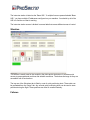


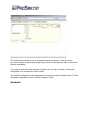

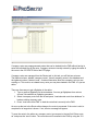


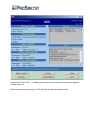
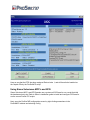
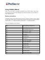


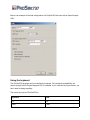


![[1 ] Oracle® Enterprise Manager](http://vs1.manualzilla.com/store/data/005669073_1-0396df232df5e560fdd03210f5126330-150x150.png)