1
User’s Manual
MOST50 E-O Converter
E-O Converter User’s Manual
Copyright © 2009 SMSC.
Jan 2009
DB0820UM1A
Page 1
MOST50 E-O Converter
Further Information
For more information on SMSC automotive products, including integrated circuits, software, and MOST
development tools and modules, visit our web site: http://www.smsc-ais.com. Direct contact information is
available at: http://www.smsc-ais.com/offices.
SMSC Europe GmbH
Bannwaldallee 48
D-76185 Karlsruhe
Germany
SMSC
80 Arkay Drive
Hauppauge, New York 11788
USA
Technical Support
Contact information for technical support is available at: http://www.smsc-ais.com/contact.
Legend
Copyright © 2009 SMSC. All rights reserved.
Ensure that all information within a document marked as 'Confidential' or 'Restricted Access' is handled solely in accordance with the agreement pursuant to which it is provided, and is not reproduced or disclosed to others without the prior written consent of SMSC. The confidential ranking of a document can be found in the footer of every page. This document supersedes and replaces all information previously supplied. The technical information in
this document loses its validity with the next edition. Although the information is believed to be accurate, no responsibility is assumed for inaccuracies.
Specifications and other documents mentioned in this document are subject to change without notice. SMSC reserves the right to make changes to this
document and to the products at any time without notice. Neither the provision of this information nor the sale of the described products conveys any
licenses under any patent rights or other intellectual property rights of SMSC or others. There are a number of patents and patents pending on the MOST
technology and other technologies. No rights under these patents are conveyed without any specific agreement between the users and the patent owners. The products may contain design defects or errors known as anomalies, including but not necessarily limited to any which may be identified in this
document, which may cause the product to deviate from published descriptions. Anomalies are described in errata sheets available upon request. SMSC
products are not designed, intended, authorized or warranted for use in any life support or other application where product failure could cause or contribute to personal injury or severe property damage. Any and all such uses without prior written approval of an officer of SMSC will be fully at your own risk.
MediaLB is a trademark, and SMSC and MOST are registered trademarks of Standard Microsystems Corporation (“SMSC”). Other names mentioned
may be trademarks of their respective holders.
SMSC DISCLAIMS AND EXCLUDES ANY AND ALL WARRANTIES, INCLUDING WITHOUT LIMITATION ANY AND ALL IMPLIED WARRANTIES
OF MERCHANTABILITY, FITNESS FOR A PARTICULAR PURPOSE, TITLE, AND AGAINST INFRINGEMENT AND THE LIKE, AND ANY AND ALL
WARRANTIES ARISING FROM ANY COURSE OF DEALING OR USAGE OF TRADE. IN NO EVENT SHALL SMSC BE LIABLE FOR ANY DIRECT,
INCIDENTAL, INDIRECT, SPECIAL, PUNITIVE, OR CONSEQUENTIAL DAMAGES; OR FOR LOST DATA, PROFITS, SAVINGS OR REVENUES OF
ANY KIND; REGARDLESS OF THE FORM OF ACTION, WHETHER BASED ON CONTRACT; TORT; NEGLIGENCE OF SMSC OR OTHERS;
STRICT LIABILITY; BREACH OF WARRANTY; OR OTHERWISE; WHETHER OR NOT ANY REMEDY OF BUYER IS HELD TO HAVE FAILED OF
ITS ESSENTIAL PURPOSE, AND WHETHER OR NOT SMSC HAS BEEN ADVISED OF THE POSSIBILITY OF SUCH DAMAGES.
E-O Converter User’s Manual
Page 2
Copyright © 2009 SMSC.
DB0820UM1A
MOST50 E-O Converter
Conventions
Within this manual, the following abbreviations and symbols are used to improve readability.
Example
BIT
FIELD.BIT
x…y
BITS[m:n]
PIN
msb, lsb
MSB, LSB
zzzzb
0xzzz
zzh
rsvd
code
Multi Word Name
Section Name
VAL
x
<Parameter>
{,Parameter}
[Parameter]
Description
Name of a single bit within a field
Name of a single bit (BIT) in FIELD
Range from x to y, inclusive
Groups of bits from m to n, inclusive
Pin Name
Most significant bit, least significant bit
Most significant byte, least significant byte
Binary number (value zzzz)
Hexadecimal number (value zzz)
Hexadecimal number (value zz)
Reserved memory location. Must write 0, read value indeterminate
Instruction code, or API function or parameter
Used for multiple words that are considered a single unit, such as:
Resource Allocate message, or Connection Label, or Decrement Stack Pointer instruction.
Section or Document name.
Over-bar indicates active low pin or register bit
Don’t care
<> indicate a Parameter is optional or is only used under some conditions
Braces indicate Parameter(s) that repeat one or more times.
Brackets indicate a nested Parameter. This Parameter is not real and actually decodes
into one or more real parameters.
E-O Converter User’s Manual
Copyright © 2009 SMSC.
DB0820UM1A
Page 3
MOST50 E-O Converter
TABLE OF CONTENTS
1 PREFACE .................................................................................................................... 5
1.1 Intended Use ....................................................................................................................................5
1.2 Deliverables ...................................................................................................................................... 5
2 INTRODUCTION ......................................................................................................... 6
3 SYSTEM EXAMPLE .................................................................................................... 8
4 BOARD DETAILS ..................................................................................................... 10
4.1 Battery Operation ...........................................................................................................................11
4.2 Physical Layer Conversion ............................................................................................................. 12
4.3 Status LEDs ................................................................................................................................... 13
4.3.1 Power ..................................................................................................................................... 13
4.3.2 Charge ................................................................................................................................... 13
4.3.3 Optical Error ...........................................................................................................................13
4.3.4 ePHY Error ............................................................................................................................. 13
5 TEST CONFIGURATIONS ........................................................................................ 14
5.1 Radiated Emissions ........................................................................................................................ 14
5.2 Bulk Current Injection ..................................................................................................................... 16
5.3 Transverse Electromagnetic Cell ................................................................................................... 18
5.4 Electrostatic Discharge ................................................................................................................... 21
APPENDIX A: SPECIFICATIONS ................................................................................ 22
APPENDIX B: TROUBLESHOOTING ......................................................................... 23
APPENDIX C: INITIAL CHARGE INSTRUCTIONS ..................................................... 24
E-O Converter User’s Manual
Page 4
Copyright © 2009 SMSC.
DB0820UM1A
Confidential
MOST50 E-O Converter
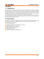
1 Preface
1.1 Intended Use
SMSC’s MOST50 E-O Converter is intended for use during development, test, and analysis of MOST50
Electrical Physical Layer (ePHY) network devices. Operation of the MOST50 E-O Converter is supported
only when used in conjunction with the components provide by SMSC, which are included in the product
deliverables (see Section 1.2). The original state of the product should not be altered; otherwise product
functionality and performance cannot be guaranteed, and user safety may be at risk.
This user’s manual should be read in its entirety prior to operating the MOST50 E-O Converter, with special consideration given to Initial Charge Instructions (Appendix C). Any reference to E-O Converter in this
document implies MOST50 E-O Converter.
1.2 Deliverables
The MOST50 E-O Converter is designed for use with the components that accompany the device in the
MOST50 E-O Converter Kit. A complete MOST50 E-O Converter Kit includes the following items:
MOST50 E-O Converter (qty: 2)
12 V Power Supply (qty: 2)
Unshielded Twisted Pair (UTP) ePHY Cable - 0.5 m (qty: 2)
Duplex Optical Fiber Cable - 3 m (qty: 1)
Duplex Optical Fiber Cable - 40 m (qty: 1)
ePHY Connector Housing (qty: 2)
Female Contacts (qty: 8)
MOST50 E-O Converter User’s Manual (qty: 1)
E-O Converter User’s Manual
Copyright © 2009 SMSC.
DB0820UM1A
Page 5
MOST50 E-O Converter
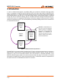
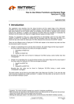
2 Introduction
In order to validate electomagnetic compatibility (EMC) and operational electrostatic discharge (ESD)
tests, it is necessary to isolate the device under test (DUT) from other nodes within the MOST50 ePHY
network (see Figure 2-1). Isolation involves eliminating the influence of the other nodes as well as external
environmental factors from the DUT. In the case of EMC testing, environmental isolation is achieved
through the use of an anechoic chamber, which is a shielded room that is designed to attenuate environmental noise sources. For operational ESD testing, the transient voltages induced on the ePHY network
need to be confined to the DUT. This is accomplished by electrically isolating the DUT ePHY network from
the other MOST50 devices.
MOST50
Network
Device
#1
MOST50
ePHY
Network
MOST50
Network
Device
(DUT)
EMC/ESD measurements for
the DUT must be performed
while the device is operating
in an active system. Electrical
isolation
is
required
to
minimize the influence of other
network devices and various
environmental factors.
MOST50
Network
Device
#2
Figure 2-1: MOST50 Network Implementation
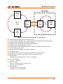
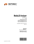
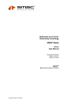
The MOST50 E-O Converter assists in isolating the DUT during a functional network test by converting a
MOST50 ePHY network into an optical physical layer network interface. Figure 2-2 shows how this is
achieved by using two E-O Converter devices. One E-O Converter is connected electrically to the
MOST50 network devices outside of the test environment while the other E-O Converter is connected
electrically to the MOST50 DUT inside of the test environment. The MOST50 network is completed when
an optical connection is made between the two E-O Converters.
E-O Converter User’s Manual
Page 6
Copyright © 2009 SMSC.
DB0820UM1A
MOST50 E-O Converter
Isolated EMC/ESD
Test Environment
MOST50
Network
Device
#1
MOST50
ePHY
Network
MOST50
E-O
Converter
(#1)
Optical Physical
Layer Network
MOST50
E-O
Converter
(#2)
MOST50
ePHY
Network
MOST50
Network
Device
(DUT)
MOST50
Network
Device
#2
Figure 2-2: MOST50 Network Implementation with DUT Isolation
The major features of the MOST50 E-O Converter include:
Conversion between MOST50 ePHY network signals and optical physical layer network signals
Minimal influence on MOST50 ePHY network messages
Protection of stimulus equipment from harsh test environments
Optical interface operable at lengths up to 50 m
Aluminum enclosure with battery power supply to reduce emissions and improve immunity
On-board battery charger circuit
Simultaneous battery charging and powering the device
Low battery indicator
Remote monitoring of ePHY errors through a Versatile Link optical transmitter
The MOST50 E-O Converter has been tested under the following conditions:
CISPR 25:2002
– Radiated and Conducted Emissions: Class 5, narrowband
ISO 11452-3:2001(E)
– 225 V/m, 1 - 400 MHz
ISO 11452-4:2001
– 200 mA, no network unlocks or coding errors
– 300 mA, no physical damage
ISO 10605:2001
– Handling: ±8 kV contact discharge
– Operational: ±15 kV air discharge
E-O Converter User’s Manual
Copyright © 2009 SMSC.
DB0820UM1A
Page 7
MOST50 E-O Converter
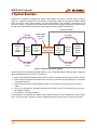
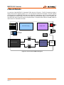
3 System Example
Instructions on setting up a sample test system are provided in this section. The test system, shown in
Figure 3-1, utilizes two MOST50 E-O Converters to electrically isolate an OS81082 Evaluation Board,
which is the DUT in this sample system. The test environment in this example is represented by the
anechoic chamber. The OptoLyzer G2 3050e serves as the MOST50 network master and is used to monitor and inject network traffic through either OptoLyzer transceiver or MOST RapidControl.
Anechoic Chamber
UTP cable
(1.0 m)
Optolyzer
G2
3050e
(Master)
MOST50
ePHY
Network
Duplex optical
fiber cable
(40 m)
MOST50
E-O
Converter
(#1)
Optical Physical
Layer Network
UTP cable
(1.0 m)
MOST50
E-O
Converter
(#2)
MOST50
ePHY
Network
OS81082
Evaluation
Board
(DUT)
UTP cable
(1.0 m)
UTP cable
(1.0 m)
Figure 3-1: MOST50 Test System Example
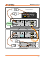
Devices used in the test system example (Figure 3-1) are connected using the following steps. Cable connections between devices are shown in Figure 3-2.
1. Connect the OS81082 Evaluation Board (DUT) to the E-O Converter (#2) with two UTP ePHY cables.
2. Connect the duplex optical fiber cable to each of the E-O Converters, ensuring that the SC connectors
are inserted correctly.
3. Connect the OptoLyzer G2 3050e (Master) to the E-O Converter (#1) using two more UTP ePHY
cables.
4. Turn on all of the devices. The ePHY and optical error LEDs on the E-O Converters will turn off once
the network is locked.
5. The system is now ready for testing.
In this example, the Optolyzer G2 3050e is able to exercise the DUT without adding any noise interference. The test can also include any number of MOST50 network devices within the anechoic chamber.
E-O Converter User’s Manual
Page 8
Copyright © 2009 SMSC.
DB0820UM1A
MOST50 E-O Converter
Stimulus Equipment
OptoLyzer
Power
OL3050e
R
M
L
Line
MOST50
ePHY
Trigger
Front Panel
OUT
Back Panel
ePHY
Error
12 - 16 V
2.5 A
OFF
Optical
Po
we
Op C ha r
tica rge
eP l Err
HY or
Er
r or
ON
MOST50
ePHY
Can be powered
by DC supply.
IN
MOST50 E-O Converter
A
B
E-O Converter
Chamber Wall
Front Panel
Back Panel
ePHY
Error
12 - 16 V
2.5 A
MOST50 E-O Converter
OFF
Battery
Powered
Optical
Po
we
Op Cha r
tica rge
eP l Err
HY or
Er
ror
ON
MOST50
ePHY
B
A
E-O Converter
OS81082 Evaluation Board
Reset
INIC
Debug Port
MOST50
ePhy
Power
9 - 16 V
ON
-
+
DUT
OFF
Anechoic Chamber
Figure 3-2: Connection Diagram
E-O Converter User’s Manual
Copyright © 2009 SMSC.
DB0820UM1A
Page 9
MOST50 E-O Converter
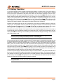
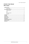
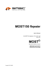
4 Board Details
An overview of the MOST50 E-O Converter PCB is shown in Figure 4-1. The E-O Converter provides a
single power jack for supplying power (12 V, 2.5 A typical) to the entire E-O Converter. This jack supports
a power plug such as Binder 99-3400-100-03 (or equivalent). Alternatively, the E-O Converter power can
be supplied by an internal battery. Power from the battery or external power supply, can be completely disconnected from the functional circuitry by the power switch. The power switch must be in the ON position in
order for the E-O Converter to function.
Up - On
Power
Power
Switch
Charge
Board Power Supply
Charger Circuit
Optical Error
Down - Off
ePHY Error
Power
Jack
ePHY
Error
Versatile Link
Transmitter
Battery
Connector
OS81082
ePHY Front End
Optical Connector
ePHY
Connector
OS81082
Figure 4-1: E-O Converter PCB Block Diagram
E-O Converter User’s Manual
Page 10
Copyright © 2009 SMSC.
DB0820UM1A
MOST50 E-O Converter
4.1 Battery Operation
An on-board charger circuit is provided, which allows the battery to charge when a DC power supply is
present at the power jack. The charger circuit automatically turns on when a DC power supply is inserted
into the power jack, independent of the power switch. When the fast-charge conditions are met, the charger circuit begins to fast-charge the battery. Fast-charge is active when the Charge LED (blue) is on. If the
battery reaches a temperature greater than 50 °C the charger circuit exits the fast-charge cycle. The fastcharge cycle typically lasts three to four hours when the battery is completely discharged. The end of the
fast-charge cycle is indicated by the Charge LED turning off. Anytime that the Charge LED is off and the DC
power supply is connected to the E-O Converter, the charger circuit trickle-charges the battery. Tricklecharge mode helps to maintain a full charge on the battery without over-charging it.
Inserting a DC power supply into an E-O Converter with a full charge on its battery results in a short fastcharge cycle. A temperature monitor ensures that the charger circuit does not enter fast-charge until the
battery temperature is less than 40 °C. The Charge LED will flash to indicate that the battery cannot enter
fast-charge mode. The Charge LED stops flashing once the battery temperature falls below 40 °C.
If the battery is severely depleted of charge and the DC power supply is plugged into the E-O Converter, a
pre-charge will occur to condition the battery for a fast-charge cycle. This pre-charge condition is also signified by the Charge LED flashing. Once the battery reaches a minimum voltage, the charger will commence
with the fast-charge cycle.
The E-O Converter uses a nickel-metal hydride rechargeable battery, therefore it is not
necessary to fully discharge the battery before it can be recharged.
When the power switch is in the ON position and the DC power supply is connected to the power jack, the
DC power supply powers the board supplies (3.3 V and 2.5 V) for the functional circuitry (data conversion).
Operation of the E-O Converter while the battery is charging can be a useful feature during compliance
testing. The E-O Converter outside of the test environment can be powered by a DC power supply, which
ensures that its battery maintains a full charge. When the battery of the E-O Converter inside of the test
environment is low, indicated by the Power LED (yellow) on, the inside and outside E-O Converters can be
switched to allow the empty battery to charge while testing continues. Switching the E-O Converters in this
manner results in minimal down time, and can easily be done between tests.
Once the DC power supply is disconnected, the charger circuit shuts down. If the power switch is ON when
this occurs, the board power supplies will continue to be powered by the battery. A full battery charge typically provides 10 hours of power for MOST50 E-O Converter operation. After approximately eight hours,
the low battery indicator Power LED (yellow) turns on. This indicates that there are less than two hours of
battery life remaining and that the battery should be recharged.
To conserve battery charge, the power switch should be turned OFF whenever tests are not
being conducted.
E-O Converter User’s Manual
Copyright © 2009 SMSC.
DB0820UM1A
Page 11
MOST50 E-O Converter
4.2 Physical Layer Conversion
The primary function of the MOST50 E-O Converter is network signal conversion between electrical and
optical physical layers. The E-O Converter incorporates two OS81082 Intelligent Network Interface Controllers
(INICs) to achieve this conversion. The network frame rate of both ePHY and optical physical layer networks is 48 kHz. One INIC receives the incoming ePHY network signal and retransmits it as the outgoing
optical physical layer network signal; the other INIC receives the incoming optical physical layer network
signal and retransmits it as the outgoing ePHY network signal. This ePHY to optical physical layer conversion is accomplished by re-clocking the MOST50 network signal while maintaining data integrity.
The optical physical layer signal is a pseudo MOST50 interface that is based on Positive Emitter Coupled
Logic (PECL). Since the optical physical layer network produces no emissions and is isolated electrically, it
can be routed through the EMC chamber wall and connected to another E-O Converter, where it is converted back to an ePHY network signal. The optical physical layer interface consists of a 1300 nm wavelength optical physical layer transceiver with a SC duplex receptacle. This allows the signal to be
transmitted over multi-mode, 62.5/125 μm glass optical fiber cable for distances up to 50 m. The
MOST50 E-O Converters can be integrated into larger chambers without adding any significant delay to
the network.
The incoming ePHY and optical physical layer network signals are checked for coding errors and network
unlocks. Any time an ePHY network error occurs, the ePHY Error LED (red) is pulsed on. Any time an optical
physical layer network error occurs, the Optical Error LED (red) is pulsed on. A coding error is indicated by an
LED (ePHY Error or Optical Error) pulse length greater than 50 ms, while a network unlock event produces a
pulse length greater than 150 ms. ePHY network errors are also conveyed from the Versatile Link optical
transmitter (see Figure 4-2). A Versatile Link optical receiver, along with a plastic optical fiber (POF) cable
can be used to capture ePHY network errors that occur during testing. This is especially useful for automated Bulk Current Injection (BCI) and Transverse Electromagnetic (TEM) cell testing, outlined in Sections 5.2
and 5.3. The pulse lengths of the ePHY network errors transmitted from the Versatile Link optical transmitter
are the same as ePHY network errors on the ePHY Error LED.
Po
we
Op Cha r
r
tic
a ge
eP l Er
HY ror
Er
ror
ePHY
Error
Optical
Versatile Link transmitter
Figure 4-2: Versatile Link Transmitter (ePHY Error)
E-O Converter User’s Manual
Page 12
Copyright © 2009 SMSC.
DB0820UM1A
MOST50 E-O Converter
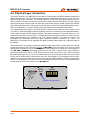
4.3 Status LEDs
The E-O Converter provides four status LEDs: Power, Charge, Optical Error, and ePHY Error. In addition, the
ePHY Error Versatile Link transmitter provides status similar to the ePHY Error LED. The status LEDs and
Versatile Link transmitter are shown in Figure 4-3.
Po
we
C
Op h a r
r
tic
a ge
eP l Er
HY ror
Err
or
ePHY
Error
Figure 4-3: LED Layout
4.3.1 Power
The Power LED provides four states that convey the following status information:
Off - The E-O Converter is not powered (power switch is OFF or battery charge is depleted).
Green - The E-O Converter is powered via the battery or the power jack (power switch is ON).
Yellow - The battery has less than two hours of charge remaining. Use the DC power supply to charge
the battery.
Flashing Green/Yellow - The battery is disconnected or defective (DC power supply is present).
4.3.2 Charge
The Charge LED is relevant only when the DC power supply is connected to the power jack. The three states
of the Charge LED include:
Off - The battery is in trickle-charge mode. This indicates that the fast charge cycle has completed and
the battery is fully charged.
Blue - The charger circuit is in fast-charge mode.
Flashing Blue - The battery cannot enter fast-charge mode because the temperature is too high or the
battery is severely discharged. In this mode, the battery is being trickle charged.
4.3.3 Optical Error
The Optical Error LED is only valid while the E-O Converter is powered (Power LED is green). The two states
for the Optical Error LED include:
Off - There are no coding errors or network unlocks from the incoming optical network.
Red - A coding error or network unlock event occurred on the incoming optical network. The pulse
width of the on cycle is greater than 50 ms for coding errors and greater than 150 ms for network
unlock events. The Optical Error LED is constantly on while the error condition persists.
4.3.4 ePHY Error
The ePHY Error LED and Versatile Link transmitter are only valid when the E-O Converter is powered (Power
LED is green). The two states for the ePHY Error LED and Versatile Link transmitter include:
Off - There are no coding errors or network unlocks from the incoming ePHY network.
Red - A coding error or network unlock event occurred on the incoming ePHY network. The pulse width
of the on cycle is greater than 50 ms for coding errors and greater than 150 ms for network unlock
events. The ePHY Error LED and Versatile Link transmitter are constantly on while the error condition
persists.
E-O Converter User’s Manual
Copyright © 2009 SMSC.
DB0820UM1A
Page 13
MOST50 E-O Converter
5 Test Configurations
The MOST50 E-O Converter can be used in a variety of tests. This chapter provides four test configuration
examples, each using a pair of E-O Converters to electrically isolate the device under test from the other
network components. The test configurations provided can be used for:
Radiated Emissions
Bulk Current Injection (BCI)
Transverse Electromagnetic (TEM) Cell
Operational Electrostatic Discharge (ESD)
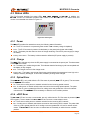
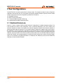
5.1 Radiated Emissions
Figure 5-1 shows a sample CISPR 25:2002 style test configuration for radiated emissions testing. Two
E-O Converters are used in the configuration. One is connected electrically to the DUT inside of the
anechoic chamber; the other is connected to the stimulus equipment outside of the anechoic chamber. A
glass optical fiber cable connects the E-O Converters together, isolating any radiated noise from the stimulus equipment. The E-O Converter is grounded to the ground plane to minimize unwanted emissions.
Figure 5-1 shows that copper tape was used to ground the E-O Converter to the ground plane inside of the
chamber. A picture of the E-O Converter is shown to further clarify how it is connected inside the chamber.
Outside the chamber, the stimulus equipment, including all other nodes that are a part of the actual application, are connected to the MOST50 network. An OptoLyzer G2 3050e may also be used outside the
chamber to monitor all MOST50 traffic.
E-O Converter User’s Manual
Page 14
Copyright © 2009 SMSC.
DB0820UM1A
MOST50 E-O Converter
Insert Picture
Master
E-O
11
4
Slave
3
8
2
9
11
10
6
12
14
13
7
1
5
8
1. DUT
2. ePHY Cable
3. MOST50 E-O Converter
4. Glass Optical Fiber (SC Duplex)
5. Ground Plane
6. Insulating Support
7. DUT Power Cable
8. Copper Tape (to ground plane)
9. Stimulus Equipment
(Including E-O Converter)
10. 12 V Battery
11. Feedthru
12. Antenna
13. LISN
14. Test Receiver
3
Figure 5-1: Radiated Emissions Test Setup
E-O Converter User’s Manual
Copyright © 2009 SMSC.
DB0820UM1A
Page 15
MOST50 E-O Converter
5.2 Bulk Current Injection
Figure 5-2 shows a sample ISO 11452-4:2001 test configuration for BCI testing. For immunity tests, the
E-O Converter inside the anechoic chamber is isolated from the ground plane by floating it on an insulating
support. This ensures that RF energy is dissipated by the DUT and not the E-O Converter. For automated
BCI testing, the E-O Converter’s ePHY Error Versatile Link transmitter output is connected by a POF cable with
Versatile Link connectors to a Versatile Link receiver outside of the chamber. Both network coding errors and
unlock events are indicated on the ePHY Error output and can be monitored and recorded at the Versatile Link
receiver.
Refer to Appendix A for Versatile Link receiver and POF cable specifications.
E-O Converter User’s Manual
Page 16
Copyright © 2009 SMSC.
DB0820UM1A
MOST50 E-O Converter
10
15
11
8
Master
E-O
9
5
11
6
14
7
Slave
3
12
1
2
4
13
11
11
17
16
1. DUT
2. ePHY Cable
3. MOST50 E-O Converter
4. Glass Optical Fiber (SC Duplex)
5. Ground Plane
6. Insulating Support
7. DUT Power Cable
8. Plastic Optical Fiber
10. 12 V Battery
11. Feedthru
12. Current Injection Probe
13. Current Monitoring Probe
14. LISN
15. ePHY Error Monitoring Receiver
16. RF Source
17. Test Receiver
9. Stimulus Equipment
(Including E-O Converter)
3
Figure 5-2: BCI Test Setup
E-O Converter User’s Manual
Copyright © 2009 SMSC.
DB0820UM1A
Page 17
MOST50 E-O Converter
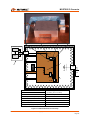
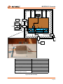
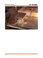
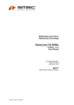
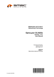
5.3 Transverse Electromagnetic Cell
Figure 5-3 shows the top and side views for a sample test configuration of an ISO 11452-3:2001(E) style
TEM cell test. The glass optical fiber isolates and protects the stimulus equipment from the electrical disturbances produced during testing. The E-O Converter inside of the TEM cell is grounded to the metal floor
using copper tape. For automated TEM Cell testing, the E-O Converter’s ePHY Error Versatile Link transmitter
output is connected by a POF cable with Versatile Link connectors to a Versatile Link receiver outside of the
TEM cell. Both network coding errors and unlock events are indicated on the ePHY Error output and can be
monitored and recorded at the Versatile Link receiver. Figure 5-4 shows a photograph of a typical TEM cell
test configuration.
E-O Converter User’s Manual
Page 18
Copyright © 2009 SMSC.
DB0820UM1A
MOST50 E-O Converter
Top View
Floor
6
15
1
7
11
2
4
3
11
12
8
Master
13
E-O
11
14
Slave
9
Side View
Septum
5
6
15
Floor
12
11
6
1
4
Master
3
E-O
13
11
11
7
2
Slave
14
10
9
1. DUT
2. ePHY Cable
3. MOST50 E-O Converter
4. Glass Optical Fiber (SC Duplex)
5. Field Probe
6. Insulating Support
7. DUT Power Cable
8. Copper Tape (to TEM Cell Floor)
9. Stimulus Equipment
(Including E-O Converter)
10. 12 V Battery
11. Feedthru
12. Plastic Optical Fiber
13. ePHY Error Monitoring Receiver
14. RF Source
15. 50 Ω Load
Figure 5-3: TEM Cell Test Setup
E-O Converter User’s Manual
Copyright © 2009 SMSC.
DB0820UM1A
Page 19
MOST50 E-O Converter
Figure 5-4: Typical E-O Converter TEM Cell Setup
E-O Converter User’s Manual
Page 20
Copyright © 2009 SMSC.
DB0820UM1A
MOST50 E-O Converter
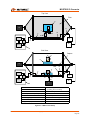
5.4 Electrostatic Discharge
Figure 5-5 shows a sample test configuration for an ISO 10605:2001 operational ESD test. The glass optical fiber isolates the stimulus equipment from the high-voltage transients that are induced on the DUT. The
E-O Converter inside the test environment is isolated from the ground plane using an insulating support.
Grounding only the DUT, with copper tape, ensures that the ESD events induced on the ePHY network are
dissipated solely through the DUT.
Master
E-O
Slave
9
5
13
4
14
6
8
7
3
1
10
2
12
1. DUT
2. ePHY Cable
3. MOST50 E-O Converter
4. Glass Optical Fiber (SC Duplex)
5. Ground Plane
6. Insulating Support
7. DUT Power Cable
8. Copper Tape (to Ground Plane)
11
9. Stimulus Equipment
(Including E-O Converter)
10.12 V Battery
11. ESD Simulator
12. ESD Gun
13. Building Ground
14. Ground Strap
3
Figure 5-5: Operational ESD Test Setup
E-O Converter User’s Manual
Copyright © 2009 SMSC.
DB0820UM1A
Page 21
MOST50 E-O Converter
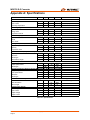
Appendix A: Specifications
Description
MOST50 E-O Converter:
Input Voltage
Min
Typ
12
Input Current
Max
Units
16
V (DC)
2.5
A (DC)
Conditions
Vin = 12 V (DC)
Operating Temperature
0
50
°C
Fast Charge Cycle:
Input Current
2.0
A (DC) power switch off
Charge Time
150
200
min.
°C
Temperature Cut-off
50
Trickle Charge Cycle:
Input Current
2.0
A (DC) power switch off, during pulse
Period
1.17
s
Pulse Width
73
ms
Battery Pack (7 Cells, 4/3 A in Series):
Output Voltage
8.4
10.5
V (DC)
Capacity
3.7
3.75
Ah
Temperature Fuse
60
°C
Optical Transceiver (Duplex, SC Receptacle):
Output Optical Power
-14
dBm avg. 62.5/125 μm fiber
Data Rate
50
Mb/s
Wavelength
1300
nm
Transmission Length
50
m
ePHY Error (Versatile Link Transmitter):
Pulse Length
50
ms
Output Optical Power
-15
dBm
Wavelength
660
nm
Versatile Link Optical Receiver (Avago HFBR-25X3Z or Equivalent) (Not Included):
Supply Voltage
3.3
V (DC)
Input Optical Power
-39
dBm
LED on
Data Rate
DC
1.0
kHz
Wavelength
660
nm
Versatile Link Plastic Optical Fiber Cable (Avago Connectors: HFBR-4531Z or equivalent) (Not Included):
mm
Fiber Diameter
1.0
core and cladding
Fiber Attenuation
Cable Length
12 V DC Power Supply:
Input Voltage
Input Current
Output Voltage
Output Current
100
0.2
50
dB/m
m
240
V (AC)
A (AC)
V (DC)
A (DC)
1.5
12
3.75
50 - 60 Hz
Table A-1: Specifications
E-O Converter User’s Manual
Page 22
Copyright © 2009 SMSC.
DB0820UM1A
MOST50 E-O Converter
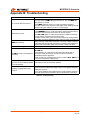
Appendix B: Troubleshooting
Problem
Solution
- Plug in the DC power supply and check if the E-O Converter powers up.
- If it now works, the Power LED (green) will turn on. Also, the Charge LED
(blue) will turn on or flash.
E-O Converter does not power on
- If the Charge LED does not turn on or flash, the battery is defective.
- If neither of these works, the power supply might not be operating correctly.
Check that the green LED is on for the 12 V power supply.
- Check the Optical Error and ePHY Error LEDs on the E-O Converters.
- If the Optical Error LED is on, make sure that the glass optical fiber cable is
hooked up correctly and the connections are securely in place.
Network does not lock
- If the ePHY Error LED is on, make sure that the ePHY cable is hooked up
correctly and the connections are securely in place.
- If neither of these works, make sure that the network has a timing-master.
- The battery is severely depleted of charge and a pre-charge is needed. The
charger will begin a fast-charge cycle when a minimum voltage is reached.
Charge LED is flashing
- The battery has recently been charged and is outside of the temperature
range to enter another fast-charge cycle. The unit is ready to be used.
Power LED is flashing green and yellow The battery is malfunctioning or has become disconnected.
- The Versatile Link transmitter should be lit at the same time as the
ePHY Error LED.
- If they both turn on, make sure that the plastic fiber optical cable is
ePHY Error Versatile Link transmitter is
connected correctly and that the Versatile Link receiver meets the
not working
specifications listed in Appendix A.
- If the Versatile Link transmitter does not turn on while the ePHY Error LED is
on, then the transmitter is malfunctioning.
Battery charge does not last more than
eight hours, or the low battery indicator - The battery is faulty and should be replaced.
turns on prematurely
- The LED lightpipe is loose by design. Check to see that the rattling is not
caused by the LED lightpipe by holding a finger on the lightpipe and gently
Something is rattling inside of the
shaking the enclosure.
enclosure
- If it is not the lightpipe, then something else is loose inside the enclosure
and could cause a short to the battery. Do not operate the E-O Converter.
Table 5-1: Troubleshooting
E-O Converter User’s Manual
Copyright © 2009 SMSC.
DB0820UM1A
Page 23
MOST50 E-O Converter
Appendix C: Initial Charge Instructions
Before using the MOST50 E-O Converter, a full charge cycle must be completed as follows:
1. Turn OFF the power switch.
2. Connect the 12 V power supply to the power jack. The Charge LED (blue) will turn on, indicating a fastcharge cycle is in progress.
3. Wait until the Charge LED turns off. The initial charge may take three to four hours to complete.
Once the initial charge is complete the E-O Converter is ready to use.
To ensure maximum battery life, do not disconnect the 12 V power supply until the fastcharge cycle is complete.
E-O Converter User’s Manual
Page 24
Copyright © 2009 SMSC.
DB0820UM1A
MOST50 E-O Converter
NOTES:
E-O Converter User’s Manual
Copyright © 2009 SMSC.
DB0820UM1A
Page 25
MOST50 E-O Converter