1
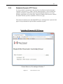
Model 8743-CL
Picomotor™ Controller/Driver
User’s Manual
ii
Preface
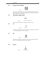
Declaration of Conformity
We declare that the accompanying product, identified with the
mark, complies
with requirements of the Electromagnetic Compatibility Directive, 2004/108/EC and
the Low Voltage Directive 2006/95/EC.
Model Numbers: 8743-CL
Year
mark affixed: 2013
Type of Equipment: Electrical equipment for measurement, control and laboratory
use in industrial locations.
Manufacturer: Newport Corporation
1791 Deere Avenue
Irvine, CA 92606
Standards Applied:
Compliance was demonstrated to the following standards to the extent applicable:
BS EN61326-1: 2006 “Electrical equipment for measurement, control and
laboratory use – EMC requirements”.
This equipment meets the CISPR 11:2009+A1:2010 Class A Group 1 radiated and
conducted emission limits.
BS EN 61010-1:2010, “Safety requirements for electrical equipment for
measurement, control and laboratory use”.
Mark Carroll
Sr. Director, Instruments Business
Newport Corporation
1791 Deere Ave, Irvine, CA92606 USA
Preface
iii
Warranty
New Focus warrants that this product will be free from defects in material and
workmanship and will comply with New Focus’s published specifications at the
time of sale for a period of one year from date of shipment. If found to be defective
during the warranty period, the product will either be repaired or replaced at New
Focus's option.
To exercise this warranty, write or call your local New Focus office or
representative, or contact Newport headquarters in Irvine, California. You will be
given prompt assistance and return instructions. Send the product, freight prepaid,
to the indicated service facility. Repairs will be made and the instrument returned
freight prepaid. Repaired products are warranted for the remainder of the original
warranty period or 90 days, whichever first occurs.
Limitation of Warranty
The above warranties do not apply to products which have been repaired or modified
without New Focus’s written approval, or products subjected to unusual physical,
thermal or electrical stress, improper installation, misuse, abuse, accident or
negligence in use, storage, transportation or handling. This warranty also does not
apply to fuses, batteries, or damage from battery leakage.
THIS WARRANTY IS IN LIEU OF ALL OTHER WARRANTIES, EXPRESSED
OR IMPLIED, INCLUDING ANY IMPLIED WARRANTY OF
MERCHANTABILITY OR FITNESS FOR A PARTICULAR USE. NEW FOCUS
SHALL NOT BE LIABLE FOR ANY INDIRECT, SPECIAL, OR
CONSEQUENTIAL DAMAGES RESULTING FROM THE PURCHASE OR USE
OF ITS PRODUCTS.
First printing 2013
© 2013 by New Focus, Santa Clara, CA. All rights reserved. No part of this manual
may be reproduced or copied without the prior written approval of New Focus.
This manual has been provided for information only and product specifications are
subject to change without notice. Any change will be reflected in future printings.
New Focus
3635 Peterson Way
Santa Clara, CA, 95054
USA
Part No. 90055151 Rev. A
iv
Preface
Confidentiality & Proprietary Rights
Reservation of Title
The New Focus programs and all materials furnished or produced in connection with
them ("Related Materials") contain trade secrets of New Focus and are for use only
in the manner expressly permitted. New Focus claims and reserves all rights and
benefits afforded under law in the Programs provided by New Focus.
New Focus shall retain full ownership of Intellectual Property Rights in and to all
development, process, align or assembly technologies developed and other
derivative work that may be developed by New Focus. Customer shall not
challenge, or cause any third party to challenge the rights of New Focus.
Preservation of Secrecy and Confidentiality and Restrictions to Access
Customer shall protect the New Focus Programs and Related Materials as trade
secrets of New Focus, and shall devote its best efforts to ensure that all its personnel
protect the New Focus Programs as trade secrets of New Focus. Customer shall not
at any time disclose New Focus's trade secrets to any other person, firm,
organization, or employee that does not need (consistent with Customer's right of
use hereunder) to obtain access to the New Focus Programs and Related Materials.
These restrictions shall not apply to information (1) generally known to the public or
obtainable from public sources; (2) readily apparent from the keyboard operations,
visual display, or output reports of the Programs; 3) previously in the possession of
Customer or subsequently developed or acquired without reliance on the New Focus
Programs; or (4) approved by New Focus for release without restriction.
Trademarks
The New Focus logo and name are registered trademarks of Newport Corporation in
Mexico, Israel, Singapore, European Union, Taiwan, Hong Kong, China, Japan,
Korea, Canada, Australia, and the United States.
Service Information
This section contains information regarding factory service for the source. The user
should not attempt any maintenance or service of the system or optional equipment
beyond the procedures outlined in this manual. Any problem that cannot be
resolved should be referred to New Focus.
Preface
v
Technical Support Contacts
North America
Europe
New Focus
3635 Peterson Way, Santa Clara, CA 95054
Telephone: (866) 683-6287
Telephone: (408) 919-1500
Newport/MICRO-CONTROLE S.A.
Zone Industrielle
45340 Beaune la Rolande, FRANCE
Telephone: (33) 02 38 40 51 56
Asia
Newport Opto-Electronics Technologies
中国 上海市 爱都路 253号 第3号楼 3层
C部位, 邮编 200131
253 Aidu Road, Bld #3, Flr 3, Sec C,
Shanghai 200131, China
Telephone: +86-21-5046 2300
Fax: +86-21-5046 2323
Newport Corporation Calling Procedure
If there are any defects in material or workmanship or a failure to meet
specifications, promptly notify Newport's Returns Department by calling 1-800-2226440 or by visiting our website at www.newport.com/returns within the warranty
period to obtain a Return Material Authorization Number (RMA#). Return the
product to Newport Corporation, freight prepaid, clearly marked with the RMA# and
we will either repair or replace it at our discretion. Newport is not responsible for
damage occurring in transit and is not obligated to accept products returned without
an RMA#.
E-mail: [email protected]
When calling New Focus Corporation, please provide the customer care
representative with the following information:
Your Contact Information
Serial number or original order number
Description of problem (i.e., hardware or software)
To help our Technical Support Representatives diagnose your problem, please note
the following conditions:
Is the system used for manufacturing or research and development?
What was the state of the system right before the problem?
Have you seen this problem before? If so, how often?
Can the system continue to operate with this problem? Or is the system nonoperational?
Can you identify anything that was different before this problem occurred?
vi
Preface
Table of Contents
Declaration of Conformity ..................................................................... ii
Warranty................................................................................................ iii
Technical Support Contacts ....................................................................v
Table of Contents .................................................................................. vi
List of Figures ....................................................................................... ix
1
Safety Precautions
1.1
1.2
1.3
1.4
2
Definitions and Symbols .............................................................10
1.1.1 General Warning or Caution ...........................................10
1.1.2 Electric Shock ..................................................................10
1.1.3 Potential Burn Hazard .....................................................10
1.1.4 European Union CE Mark ...............................................11
1.1.5 Alternating voltage symbol .............................................11
1.1.6 On ....................................................................................11
1.1.7 Off....................................................................................11
1.1.8 Ground .............................................................................11
1.1.9 DC Symbol ......................................................................12
1.1.10 Waste Electrical and Electronic Equipment (WEEE) .....12
1.1.11 Control of Hazardous Substances ....................................12
Warnings and Cautions................................................................13
1.2.1 General Warnings ............................................................13
1.2.2 General Cautions .............................................................14
1.2.3 Summary of Warnings and Cautions ...............................14
Location of Labels and Warnings................................................17
Safety Grounding Considerations................................................18
General Information
2.1
2.2
2.3
2.4
2.5
2.6
10
19
System Overview.........................................................................19
Scope of this Manual ...................................................................20
Unpacking and Inspection ...........................................................20
2.3.1 What is included ..............................................................20
Available accessories...................................................................20
Safety ...........................................................................................21
Specifications ..............................................................................22
Preface
vii
2.6.1
2.6.2
3
Theory of Operation
3.1
3.2
3.3
3.4
3.5
3.6
3.7
4
4.6
4.7
31
Introduction .................................................................................31
Grounding ....................................................................................31
Power ...........................................................................................31
Connecting 8743-CL to a Computer via USB .............................31
Connecting 8743-CL to a Computer via Ethernet .......................32
4.5.1 Connecting to a Router ....................................................32
Picomotor Connections ...............................................................33
4.6.1 Motor Connectors ............................................................33
4.6.2 Feedback Connectors.......................................................34
Connecting Multiple Units to a Computer ..................................35
4.7.1 Using USB Hubs .............................................................37
4.7.2 Using Ethernet Routers/Switchers ...................................38
4.7.3 Using RS-485 LAN to Daisy-Chain ................................39
Computer Interfacing
5.1
5.2
5.3
24
How the Picomotor Actuator Works ...........................................24
Stepping the Picomotor with the 8743-CL Controller/Driver .....24
Closed-Loop Operation ...............................................................25
Status Indicator ............................................................................26
Power Supply...............................................................................27
3.5.1 Fault Protection ...............................................................27
Input / Output Connections .........................................................28
3.6.1 USB .................................................................................29
3.6.2 Ethernet............................................................................29
3.6.3 RS-485 .............................................................................29
3.6.4 Power ...............................................................................30
3.6.5 Picomotor Interfaces ........................................................30
Mounting the unit ........................................................................30
Initial Setup
4.1
4.2
4.3
4.4
4.5
5
Operating Limits* ............................................................22
Weight, Dimensions ........................................................23
41
Introduction .................................................................................41
Computer Interface Terminology ................................................41
USB Communication...................................................................42
5.3.1 USB Command Termination ...........................................42
viii
Preface
5.4
5.5
5.6
5.7
6
Remote Command Set
6.1
6.2
7
114
Non Axis-Specific Error Messages ...........................................114
Axis-Specific Error Messages ...................................................115
Maintenance and Service
8.1
8.2
8.3
8.4
8.5
8.6
63
Command Syntax ........................................................................63
6.1.1 RS-485 Command Syntax ...............................................64
6.1.2 Summary of Command Syntax .......................................65
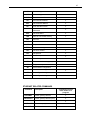
Command List .............................................................................66
6.2.1 Description of Commands ...............................................69
Appendix
7.1
7.2
8
Ethernet Communication .............................................................42
5.4.1 Ethernet Dynamic and Static IP Address Setup ..............43
5.4.2 Ethernet Peer-to-Peer Setup ............................................43
5.4.3 Communicating Using a Hostname .................................44
RS-485 Communication ..............................................................45
5.5.1 Setting up an RS-485 Network ........................................46
5.5.2 Communication with a Slave Controller .........................47
Picomotor Controller Software Application ................................48
5.6.1 Introduction .....................................................................48
5.6.2 Overview .........................................................................49
5.6.3 Homing Methods .............................................................53
5.6.4 Embedded Dynamic HTTP Server ..................................61
LabVIEWTM and C# Programming Support ...............................62
5.7.1 Introduction .....................................................................62
118
Enclosure Cleaning ....................................................................118
Technical Support ......................................................................118
Service .......................................................................................119
Obtaining Service ......................................................................119
Warranty ....................................................................................119
Service Form .............................................................................120
Preface
ix
List of Figures
Figure 1
Figure 2
Figure 3
Figure 4
Figure 5
Figure 6
Figure 7
Figure 8
Figure 9
Figure 10
Figure 11
Figure 12
Figure 13
Figure 14
Figure 15
Figure 16
Figure 17
Figure 18
Figure 19
Figure 20
Figure 21
Figure 22
Figure 23
Figure 24
Figure 25
Figure 26
Figure 27
Figure 28
Figure 29
Figure 30
Figure 31
Figure 32
Figure 33
Figure 34
Figure 35
Figure 36
Figure 37
Figure 38
Figure 39
Figure 40
General Warning or Caution Symbol ........................................... 10
Electrical Shock Symbol ............................................................... 10
Hot Surface Symbol ..................................................................... 10
CE Mark ........................................................................................ 11
Alternating Voltage Symbol ......................................................... 11
On Symbol .................................................................................... 11
Off Symbol.................................................................................... 11
Ground Symbol ............................................................................ 11
DC Symbol.................................................................................... 12
WEEE Directive Symbol .............................................................. 12
RoHS Compliant Symbol ............................................................. 12
Labels and Warnings..................................................................... 17
Dimensional Outline Drawing ...................................................... 23
Servo Loop .................................................................................... 25
Status Indicators position .............................................................. 26
Heatsink mounting slots ................................................................ 28
8743-CL Inputs and Outputs......................................................... 29
Motor and Feedback Connectors .................................................. 33
L-bracket ....................................................................................... 35
Using L-brackets to stack up several Controllers ......................... 35
Multiple Units Stacking & Interconnection .................................. 36
Connecting four units to a computer via a USB hub .................... 37
Connecting three units to a computer via an Ethernet router........ 38
Connecting four units to a computer via RS-485 LAN ................ 39
Connecting four units to a computer via RS-485 adapter ............. 40
Picomotor Controller RS-485 LAN Topology ............................. 46
Picomotor Application Software................................................... 48
Controller Address Identification ................................................. 49
Jog Tab .......................................................................................... 50
Cycle Tab ...................................................................................... 51
Terminal Tab ................................................................................. 52
Home Tab...................................................................................... 53
Setup Window (Closed-Loop) ...................................................... 55
Options Window ........................................................................... 56
Properties Window........................................................................ 57
Controller Scan ............................................................................. 58
Address Conflict Resolution Window .......................................... 59
Device Address Window .............................................................. 60
Internet Browser View .................................................................. 61
Command Syntax Diagram ........................................................... 63
1
Safety Precautions
1.1
Definitions and Symbols
The following terms and symbols are used in this documentation and also appear on
the Model 8743-CL Controller/Driver where safety-related issues occur.
1.1.1
General Warning or Caution
Figure 1
General Warning or Caution Symbol
The Exclamation Symbol in the figure above appears on the product and in Warning
and Caution tables throughout this document. This symbol designates that
documentation needs to be consulted to determine the nature of a potential hazard,
and any actions that have to be taken.
1.1.2
Electric Shock
Figure 2
Electrical Shock Symbol
The Electrical Shock Symbol in the figure above appears throughout this manual
and on the product. This symbol indicates a hazard arising from dangerous voltage.
Any mishandling could result in irreparable damage to the equipment, and personal
injury or death.
1.1.3
Potential Burn Hazard
Figure 3
Hot Surface Symbol
The Hot Surface Symbol in the figure above appears throughout this manual and on
the product. This symbol indicates a hazard arising from a high temperature. Any
mishandling could result in personal injury.
Specifications
1.1.4
11
European Union CE Mark
Figure 4
CE Mark
The presence of the CE Mark on New Focus equipment means that this instrument
has been designed, tested and certified compliant to all applicable European Union
(CE) regulations and recommendations.
1.1.5
Alternating voltage symbol
~
Figure 5
Alternating Voltage Symbol
This international symbol implies an alternating voltage or current.
1.1.6
On
I
Figure 6
On Symbol
The symbol in the figure above represents a power switch position on a Model 8743CL. This symbol represents a Power On condition.
1.1.7
Off
Figure 7
Off Symbol
The symbol in the figure above represents a power switch position on the Model
8743-CL. This symbol represents a Power Off condition.
1.1.8
Ground
Figure 8
Ground Symbol
12
Introduction
The symbol in the figure above appears on the Model 8743-CL to indicate the screw
to be used to ground the case of the unit. This symbol identifies the frame or chassis
terminal.
1.1.9
DC Symbol
Figure 9
DC Symbol
This international symbol implies an unvarying current or voltage.
1.1.10
Waste Electrical and Electronic Equipment (WEEE)
Figure 10
WEEE Directive Symbol
This symbol on the product or on its packaging indicates that this product must not
be disposed with regular waste. Instead, it is the user responsibility to dispose of
waste equipment according to the local laws. The separate collection and recycling
of the waste equipment at the time of disposal will help to conserve natural
resources and ensure that it is recycled in a manner that protects human health and
the environment. For information about where the user can drop off the waste
equipment for recycling, please contact your local New Focus representative.
1.1.11
Control of Hazardous Substances
Figure 11
RoHS Compliant Symbol
This label indicates the products comply with the EU Directive 2002/95/EC that
restricts the content of six hazardous chemicals.
Specifications
1.2
13
Warnings and Cautions
The Model 8743-CL is a component of a system that will contain one or more
Picomotors and other items. Since New Focus cannot control these other system
components, the User is ultimately responsible for ensuring that the complete system
meets all applicable product and workplace safety regulations. Specific attention
should be directed to the description of safety grounding concerns described in
Section 1.4, below.
The following are definitions of the Warnings, Cautions and Notes that are used
throughout this manual to call your attention to important information regarding
your safety, the safety and preservation of your equipment or an important tip.
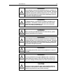
WARNING
Situation has the potential to cause bodily harm or death.
CAUTION
Situation has the potential to cause damage to property or
equipment.
NOTE
Additional information the user or operator should consider.
Situation has the potential to cause the product to not comply
with applicable European Union regulations.
1.2.1
General Warnings
Observe these general warnings when operating or servicing this equipment:
Heed all warnings on the unit and in the operating instructions.
Do not use this equipment in or near water.
Although the input power to this equipment is below 20 VDC, this equipment internally
generates much higher voltages that are present on the Model 8743-CL connector pins. Only
properly trained personnel should touch either of these items.
The Model 8743-CL is intended to be used as a component in a larger system. When this
product is included as part of a larger assembly, the user MUST ensure that appropriate
additional safety and EMC-compliance features are incorporated the assembly.
The Model 8743-CL is typically supplied with an external DC power source. When the external
power source is connected to MAINS power, the external power source’s detachable power cord
14
Introduction
may be used to disconnect power to the 8743-CL. Do not position the external power supply so
that its MAINS power cord cannot be easily disconnected.
Disconnect power before cleaning the equipment. Do not use liquid or aerosol cleaners; use
only a damp lint-free cloth.
Lockout all electrical power sources before servicing the equipment.
There are no user-replaceable fuses in this equipment. The user must ensure that appropriate
current-limiting protection is provided by the external DC power source.
To avoid explosion, do not operate this equipment in an explosive atmosphere.
Qualified service personnel should perform safety checks after any service.
Use only the New Focus-supplied MAINS power cord with the external DC supply. Use of
under-rated power cords and cause property damage
1.2.2
General Cautions
Observe these cautions when operating this equipment:
If this equipment is used in a manner not specified in this manual, the protection provided by
this equipment may be impaired.
Do not block ventilation openings.
Use only the specified replacement parts.
Follow precautions for static sensitive devices when handling this equipment.
This product should only be powered as described in the manual.
There are no user-serviceable parts inside the Model 8743-CL Picomotor Drive Module.
1.2.3
Summary of Warnings and Cautions
The following general warning and cautions are applicable to this instrument:
WARNING
The Picomotor Controller/Driver is incomplete in constructional
features and is considered only to be a component for the
purposes of regulatory compliance. It is “equipment for building
in;” a suitable enclosure must be provided so that the unit is not
user accessible when incorporated into the final product.
WARNING
The Model 8743-CL Picomotor Controller/Driver internally
generates non-SELV voltages. These voltages are present, at
times, on the Picomotor connectors even when a Picomotor is
not connected. The user shall mount the Model 8743-CL with
appropriate barriers, spacings, markings, etc. to ensure that all
applicable regulatory requirements are met. THIS IS THE
USER’S RESPONSIBILITY.
Specifications
15
WARNING
Do not attempt to operate this equipment if there is evidence of
shipping damage or you suspect the unit is damaged. Damaged
equipment may present additional hazards to you. Contact New
Focus technical support for advice before attempting to plug in
and operate damaged equipment.
WARNING
The Model 8743-CL is intended for use ONLY with New Focus
Picomotors. Connection of other devices to the unit’s motor
connectors may cause damage to the unit or the connected
device, fire, and/or personal injury.
WARNING
Before operating the Model 8743-CL Picomotor Driver, please
read and understand all of Section 1.
WARNING
Do not attempt to operate this equipment if there is evidence of
shipping damage or you suspect the unit is damaged. Damaged
equipment may present additional hazards to you. Contact New
Focus technical support for advice before attempting to plug in
and operate damaged equipment.
WARNING
Do not apply external DC power to this equipment in excess of
14.5 VDC.
WARNING
Use only the New Focus-supplied MAINS power cord with the
external DC power supply. Use of an under-rated power cord
may cause damage to the product, fire, and/or personal injury.
CAUTION
There are no user serviceable parts inside the Model 8743-CL
Picomotor Controller/Driver. Work performed by persons not
authorized by New Focus will void the warranty.
16
Introduction
WARNING
If this equipment is used in a manner not specified in this
manual, the protection provided by this equipment may be
impaired.
WARNING
This instrument is intended for use by qualified personnel who
recognize thermal, shock, or laser hazards and are familiar with
safety precautions required to avoid possible injury. Read the
instruction manual thoroughly before using, to become familiar
with the instrument’s operations and capabilities.
CAUTION
The Model 8743-CL Picomotor Controller/Driver is designed to
be safe when operated under Normal Environmental Conditions
as defined in EN61010-1:2010. Operation under harsher
environmental conditions can result in severe injury.
CAUTION
The case of the Model 8743-CL Picomotor Controller/Driver is
used to dissipate internally-generated heat. Blocking the normal
convective airflow around the unit, or thermally insulating the
unit, can result in severe injury, damage to the product, and/or
fire.
CAUTION
When operated at higher pulse rates for extended periods of
time, the temperature on the outside of the Model 8743-CL’s case
may rise above the “surface temperature limits in normal
operation” as defined in EN61010-1:2010 unless the user takes
appropriate measures. These may include the addition of an
external heat sink, barriers to contact, reducing the pulse
frequency, or other appropriate mitigations. Failure to take
appropriate action when operating the Model 8743-CL under
these conditions can result in severe injury.
The Model 8743-CL Picomotor Controller/Driver is intended for
use in an industrial laboratory environment. Use of this product
in other environments, such as residential, may result in
electromagnetic compatibility difficulties due to conducted as
well as radiated disturbances.
Specifications
1.3
17
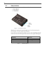
Location of Labels and Warnings
Power Supply
Voltage and
Current
CE Mark
High Voltage
Warning
Symbol
Model
Number
Serial Number
and WEEE
Symbol
Applicable
US Patents
Chassis Ground
Identification
Figure 12
Labels and Warnings
18
Introduction
1.4
Safety Grounding Considerations
There are potentially lethal voltages generated within the Model 8743-CL Picomotor
Controller/Driver and presented on the pins of the “Motor” connectors EVEN
WHEN NO PICOMOTOR IS INSTALLED. (These voltages are not present when
power is not applied to the unit. They are not present when the unit is switched
OFF.) The User must manage certain system-level aspects to ensure safe operation.
One of these is grounding.
The Model 8743-CL’s external DC power supply provides 12VDC. The negative
output from this supply is typically isolated from MAINS earth ground, but this
isolation should not be assumed. This same negative output is connected directly to
the Model 8743-CL’s external case within the Model 8743-CL. This same “ground”
is at the same potential as the MOTOR connectors’ return signal pins. This means
that the MOTOR connectors’ drive signal pins are, at times, at VERY HIGH
VOLTAGES relative to the Model 8743-CL case, the USB connector shell, and the
DC input/loop-through connectors’ negative terminals.
An 8-32 screw is provided on the unit and marked with the “Ground” symbol shown
in Paragraph 1.1.8, above. While it is not necessary to connect this terminal to a
building “earth” ground, New Focus recommends doing so because it will simplify
system-level compliance with most regulatory requirements. Once this connection
is made, the user must ensure that all other system components are appropriately
grounded. Do not depend upon the physical mounting hardware to accomplish this
grounding.
If the other components are not grounded, a damaged Picomotor (or its wire) could
result in a dangerously high voltage being present between anything that is grounded
(like the 8743-CL and a computer attached to it via USB) and the Picomotor case.
Note that the simplest way to ground a Picomotor is via its threaded mounting
bushing or other mounting hardware. DO NOT ATTEMPT TO OPEN A
PICOMOTOR TO ACHIEVE THIS GROUNDING.
If system requirements prevent the Picomotor from being grounded, then the user
must ensure that the Model 8743-CL and all other system components (including
any USB-connected computers) are properly isolated from earth ground. This is
because a short of the high-voltage drive signal to an earth ground may result in
potentially lethal voltages existing between the case of the 8743-CL and anything
that is earth grounded, such as a floor. The User is advised to consult all applicable
regulations because this insulation will probably need to have a breakdown voltage
of several thousand volts due to lightening concerns.
In summary, New Focus strongly recommends grounding the Model 8743-CL’s
case.
2
General Information
2.1
System Overview
8743-CL is a 2-axis closed-loop motion controller/driver for Picomotors, offering a
complete motion solution for many applications. It can control up to 2 Picomotors
and it can work in systems with other Model 8743-CL and 8743-CL
Controller/Drivers to drive a large number of Picomotors. The controller can be
programmed via USB, Ethernet, and RS-485 communication interfaces to perform
different motion tasks: relative and absolute moves, jogging, etc.
Key Product Features
A number of advanced features make the 8743-CL an excellent choice for many
applications:
Intelligent 2-axis closed-loop control
Compact, integrated controller and driver design
Patented Picomotor™ compatibility with auto-sensing technology
Programmable settings stored in non-volatile memory
Plug-and-play USB 2.0 interface
10/100-Mbps Ethernet connectivity (Sockets interface, TCP/IP, DHCP, UDP)
Embedded dynamic HTTP server
RS-485 LAN Daisy-chain Capability
Over temperature protection
Advanced microcontroller technology
Embedded real-time operating system
Easy to use Windows software utility
LabVIEWTM and C# programming support
Local Power ON / OFF Switch
20
Introduction
2.2
Scope of this Manual
Please carefully read this instruction manual before using the 8743-CL Picomotor
Controller/Driver. Be especially careful to observe the warnings and cautions
throughout this manual (see Safety Symbols and Terms). If any operating
instructions are not clear, contact New Focus.
This instruction manual contains the necessary information for operation and
maintenance of the Model 8743-CL, as well as information for troubleshooting and
obtaining service if necessary.
2.3
Unpacking and Inspection
The Model 8743-CL is carefully assembled, tested and inspected before shipment.
Upon receiving this instrument, check for any obvious signs of physical damage that
might have occurred during shipment. Report any such damage to the shipping
agent immediately.
NOTE
Retain the original packing materials in case reshipment becomes necessary.
2.3.1
What is included
The 8743-CL package contents:
2.4
8743-CL Controller/Driver
USB Flash Drive which contains the user manual, various documents, USB
driver, software application and libraries.
Available accessories
Power supply/AC adapter, 60 Watt (Model 8745-PS)
Power supply link cable, 6 inch, for daisy chaining multiple controllers together
using a single 12 VDC supply (Model 8745-PWR-CBL)
RS-485 LAN link cable, 6 inch, for daisy-chaining (Model 8745-RS485-CBL)
USB cable, 3 meter micro-B to USB-A cable (Model 8745-USB-CBL)
L-shaped bracket for stacking several Controllers/Drivers (Model 8745-STK-KIT)
Optical table mounting plate kit (Model 8745-MTG-KIT)
Specifications
2.5
21
Safety
Voltages of up to 130 V are accessible inside the 8743-CL Controller/Driver chassis,
mounts, and Picomotors. DO NOT operate the units with the driver or mount covers
removed. If the wire of a mount or Picomotor is damaged, discontinue use and
return it for repair. If the device is used in a manner not specified by New Focus, the
protection provided by the device may be impaired.
Normally, the case of the Model 8743-CL will rise a few degrees when a Picomotor
is moved. Under conditions of extreme use, meaning long distance moves on one or
more motor channels, the case temperature may rise above what is considered safe
under various international safety conventions. Even after extreme use, the unit’s
case temperature will drop to safe levels within a few minutes. The user should not
touch the case immediately following such use. Note that the Model 8743-CL does
contain internal temperature protection circuitry that will shut down the unit when
the case approaches a temperature that could degrade or damage the unit.
CAUTION
The case of the Model 8743-CL Picomotor
Controller/Driver is used to dissipate internallygenerated heat. Blocking the normal convective
airflow around the unit, or thermally insulating the
unit, can result in severe injury, damage to the
product, and/or fire.
2.6
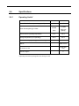
Specifications
2.6.1
Operating Limits*
PARAMETER
Model 8743-CL Power input voltage (+V IN)
Power Consumption @ 12 Volts
Ambient still-air operating temperature
Storage temperature (non-operating)
Relative Humidity, operating (non-condensing)
Altitude
MIN.
MAX.
10.5 V
14.5 V
2 Watts
11 Watts
(Idle)
(@ 2 kHz
speed)
0 °C
65 °C
-40 °C
95 °C
10%
90%
2000 meters
Environment, Use
Indoor Use
Only
Pollution Degree
2
*Operating outside the operating limits may damage the unit.
23
2.6.2
Weight, Dimensions
Weight
9.5 oz (270 g)
(L x W x H)
Dimensions
5.84 in x 3.61 in x 1.02 in
148.3 mm x 91.7 mm x 25.9 mm
Figure 13
Dimensional Outline Drawing
24
3
Theory of Operation
3.1
How the Picomotor Actuator Works
The patented design of the Picomotor actuator relies on the basic difference between
dynamic and static friction. A graphic example of this is the “tablecloth trick”, in which a
quick pull of the cloth leaves the dishes on the table, while a slow pull of the tablecloth
ends up pulling the dishes off the table (high static friction).
The Picomotor actuator uses the same principle with a threaded jaw, similar to two halves
of a split nut, clamped around a precision 80-pitch screw. One jaw is connected to one end
of a piezoelectric transducer, and the other jaw is connected to the other end of the
transducer. A slow electrical signal applied to the piezo slowly changes the length,
causing the two jaws to slide in opposite direction. This slow sliding motion makes the
screw turn (static friction). At the end of the transducer motion, a fast electrical signal
quickly returns the jaws to their starting positions. Because of the screw’s inertia and low
dynamic friction, it remains motionless, holding its position. Simply reversing the order of
the fast and slow signals reverses the direction of rotation.
3.2
Stepping the Picomotor with the 8743-CL Controller/Driver
Although the Picomotor is not a stepper, per se, it can be driven step-by-step. Each step
size depends on the Picomotor model, but it is usually < 30nm, allowing for very small,
controlled movements.
8743-CL can be programmed for single step control, as well as a predetermined number of
steps. Moreover, 8743-CL can drive the Picomotor in a continuous motion, in either
direction at variable speeds.
As opposed to magnetic motors, the Picomotor actuator has a set-and-forget stability.
When no power is applied, the actuator does not move. The user can feel confident that the
Picomotor will not change its position, even when the 8743-CL Controller/Driver is
powered off. Therefore, the 8743-CL has a power ON/OFF switch for convenience. If a
user has a 2-Picomotor system, once the system is set, the user can turn the power OFF, to
assure that the Picomotors will not be inadvertently moved through computer control. In
addition, the 8743-CL Controller/Driver can be programmed with the outputs
disconnected, with the same effect as in the power OFF state.
25
3.3
Closed-Loop Operation
The Model 8743-CL can operate in an open-loop mode with either closed-loop or openloop Picomotors. In addition, it can operate in closed-loop mode when connected to
closed-loop Picomotors. The unit will also support mixed operation whereby an open-loop
Picomotor is operated in open-loop mode on one axis and a closed-loop Picomotor is
operated in closed-loop (or open-loop) mode on the other axis.
While operating in closed-loop mode, the Model 8743-CL will respond to motion
command displacements based upon increments of the closed-loop Picomotor positioner’s
internal optical encoder, rather than by actual Picomotor steps. The controller will
automatically determine the appropriate number of Picomotor STEPS needed to
accomplish the target COUNTS displacement.
Closed-loop correction takes affect only during position regulation (holding position) as
opposed to while moving. Furthermore, the positioning units must be in ‘Counts’ (see SN
command) and closed-loop positioning must be enabled (see MM command) for
corrections to occur.
The 8743-CL closed-loop update interval is programmable and can be set from 0.1 second
to about 27 hours. Moreover, for maximum user application flexibility, each axis’
parameter settings are independent and can, therefore, be set to a different interval rate.
NOTE: Closed-Loop correction is automatically disabled after a controller reset,
power-up, or a Following Error condition (see FE command).
NOTE: The user can enable Closed-Loop mode via MM command or by clicking the
Enable Closed-Loop button in the Windows software application.
NOTE: When controlling a standard open-loop Picomotor positioner (1) set ‘Units’
option to ‘Steps’ and (2) disable ‘Travel Limit Checking.’
Figure 14
Servo Loop
26
3.4
Status Indicator
The LED located near the power switch has several functions:
Power Indicator
Status Indicator
Troubleshooter
Status
Indicator
Power
Switch
Figure 15
Status Indicators position
When the unit is turned on the unit goes through a series of verifications and turns the
LED solid green. The unit is ready to drive Picomotors.
If any problems are found, the LED will blink or turn on a color corresponding to the issue
found. Please refer to the following table and contact New Focus support if this happens.
CONDITION
No power applied to unit
Unit OK; no critical errors detected
Reboot condition occurred
Corrupted firmware detected
Critical fault detected (e.g. over-temperature)
Table 1
LED STATE
OFF
Solid green
Fast blinking green for 0.5 second
Solid amber
Solid red
LED Status Indicator
27
3.5
Power Supply
The 8743-CL Controller/Driver can place stress on the system power supply. The stress
has two components:
Inrush current: The inrush current on power-up charges the internal filter capacitor.
While the energy magnitude of the inrush current is limited, it can still cause problems
with power supplies not designed to handle it.
Dynamic load: Dynamic current is supplied to the 8743-CL internal power supply for
each Picomotor drive pulse. The input-filter capacitor will supply more dynamic current as
the resistance between the capacitor and system power supply increases. Do not increase
this resistance: it will increase ripple-current stress on the internal input-filter capacitor,
leading to early failure of the Model 8743-CL. The best strategy is to keep the resistance
between the power supply and the 8743-CL below 0.1 Ω and use the power supply
recommended by New Focus that came with the 8743-CL Controller/Driver.
3.5.1
Fault Protection
The 8743-CL Controller/Driver incorporates circuit-protection schemes to protect itself
and the system power supply:
Over-voltage protection: If the power input voltage exceeds 16.7 to 18.5 V, a transient
voltage suppressor (TVS) shunts the power input to ground. The internal 2.5 A fuse will
then open. The TVS will also shunt the power input to ground if an internal fault shorts
any high voltage to the power input. The input fuse will also open if the input power
voltage is reversed. Brief power supply transients will not blow the fuse. Therefore, it is
highly recommended to use the correct New Focus-supplied power supply. If the fuse was
blown, the unit has to be serviced by New Focus. It is not user replaceable.
Over-temperature protection: If the base plate of the unit reaches 80 °C, the unit will
turn the status indicator solid red to tell the user that the base plate, which acts as a
heatsink, reached the maximum allowed temperature. The user is expected to take some
measures like decreasing the pulse rate, force-air cool the 8743-CL case, or use an extra
heatsink. If the case temperature continues to rise, at 85 °C the output will be turned off.
The output will remain off until the base plate temperature decreases to 75 °C, when the
output will be ready to drive the motor again. In that case the status indicator will turn
solid green to indicate that the normal operation has resumed (see Table 1). If left
unattended, the unit will protect itself cycling between 85 °C and 75 °C.
The unit does not need an extra heatsink in normal laboratory environment. However, if
forced cooling is needed, usually at high ambient temperatures, a heatsink can be mounted
using the 4 slots of the unit base (see Figure 16).
28
A heatsink can
be mounted
using these slots
Figure 16
3.6
Heatsink mounting slots
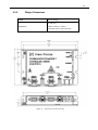
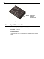
Input / Output Connections
Figure 16 shows the 8743-CL input and output connections.
Communication Interfaces: USB, Ethernet, RS-485 (2)
Power Inputs: +12VDC (2)
Picomotor Interfaces: 4
The following figure shows the position of the inputs and outputs as well as the power
switch.
29
Figure 17
3.6.1
8743-CL Inputs and Outputs
USB
The USB input is a Micro-AB connector. Use a Micro-B to USB-A cable to connect the
8743-CL Controller/Driver to a computer.
3.6.2
Ethernet
The Ethernet input is a standard RJ-45 connector. Use a Cat 5 Ethernet cable to connect
the 8743-CL Controller/Driver to a router, an Ethernet switch, or a computer.
3.6.3
RS-485
There are two RS-485 connectors that accept standard 3.5mm stereo plugs. The two
connectors are connected in parallel inside the Model 8743-CL. (The wiring convention is
TIP = D+, RING = D-, SLEEVE = GND.) These connections are used to simplify the
wiring between an external computer and multiple 8743-CL or 8743-CL Controller/Driver
units.
See Section 4.7.3 Using RS-485 LAN to Daisy-Chain and Section 5.5 RS-485
Communication for more information on setting up these configurations. See the
Accessories Section 2.4 for information on an RS-485 cable that will facilitate normal
multi-unit linking.
30
3.6.4
Power
There are two power inputs that can take a standard barrel connector with the output
diameter 5.5 mm and internal diameter 2.1 mm. The provided power supply can be
plugged in either of these two connectors. The other connector is used to link the power
supply to another 8743-CL Controller/Driver. See the Accessories Section 2.4 for
information on the Power supply link cable.
Use the power switch to turn the unit ON and check the LED status as described in Section
3.4.
3.6.5
Picomotor Interfaces
Each 8743-CL can drive up to 2 Picomotors, one motor at a time. Before connecting,
inspect the Picomotor cables, connectors and generally their integrity. The Picomotors will
receive high voltage pulses that can be dangerous if wires are exposed. Contact New
Focus if you see any problems.
The 8743-CL will support both Open-loop and Closed-Loop Picomotors. The modular
RJ-22 connectors on the 8743-CL provide the drive voltages to both types. Closed-Loop
Picomotors have an additional High-Density DB-15 connector that provides the required
feedback signals. The feedback signals typically include I/Q position, limit sense, index
position, and / or home position information, depending upon the type of Closed-Loop
Picomotor.
Do not connect anything else to the 8743-CL outputs. The Controller/Driver is designed to
handle only New Focus standard Picomotors. If the output is shortened or otherwise
misused, an internal component will open and the unit will have to be serviced.
3.7
Mounting the unit
8743-CL may be set on a table top.
While not required, the 8743-CL can be bolted to the table top in either horizontal or
vertical orientation.
Under conditions of extreme usage, the case temperature of the Model 8743-CL may
exceed the levels considered safe by various international safety conventions. If such use
is anticipated, the user must position, or block access to, the unit so that the unit cannot be
accidentally touched.
31
4
Initial Setup
4.1
Introduction
This section contains information on how to connect the 8743-CL Controller/Driver to
your local line voltage and how to connect the Picomotor to the controller. It also includes
a discussion about the remote interface and the instrument’s power-up.
4.2
Grounding
Connect the 8-32 grounding screw to a good earth ground using a dedicated wire of at least
20AWG diameter. See Section 1.4 for advice on making this connection
4.3
Power
Make sure that that power switch is in the off position. Connect the external power supply
to AC and connect the power barrel plug into one of the 8743-CL power inputs. If more
than one unit needs to be connected to the same power supply use the power link cable to
daisy-chain them. Up to 3 units can be powered by one power supply.
4.4
Connecting 8743-CL to a Computer via USB
The 8743-CL Controller/Driver can be connected to a computer with a standard Micro-B
to USB-A cable. If several 8743-CL units have to be connected to the same computer the
user can connect them to a USB hub and then connect the hub to the computer USB input.
Alternatively, the first unit can be connected to the computer with subsequent units daisychained as described in Section 4.7.3 Using RS-485 LAN to Daisy-Chain.
32
4.5
4.5.1
Connecting 8743-CL to a Computer via Ethernet
Connecting to a Router
The 8743-CL Controller/Driver can be connected to an Ethernet Router. Attach the
computer Ethernet cable to the same router. If desired, the router can be attached to a
WAN (Wide Area Network) so that the computer can also be connected to internet, or
company network.
By default, the 8743-CL Controller/Driver is set for DHCP (Dynamic Host Configuration
Protocol). This means that, when connected to a router which is set in DHCP mode, the
router will automatically assign it a local IP address from the router address pool. The
computer will also receive a local IP address. The IP address normally will be in the range
of 192.168.1.1 to 192.168.255.255. Check your router settings to verify the IP address
pool.
As soon as both units, 8743-CL and computer, are connected to the router the Picomotor
Controller/Driver is ready to communicate with the computer. The discovery utility will
automatically find the IP address of the 8743-CL Controller/Driver and the user can start
sending commands to the unit. See Section 5 for details.
If several 8743-CL units have to be connected to the same computer the user can connect
them individually to an Ethernet hub or router. Alternatively, the first unit can be
connected to the router (or computer) with subsequent units daisy-chained as described in
Section 4.7.3 Using RS-485 LAN to Daisy-Chain.
33
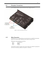
4.6
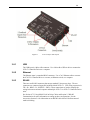
Picomotor Connections
Each 8743-CL axis has its own set of positioner interfacing connectors. In total there are
two(2) feedback interface connectors and two(2) motor output connectors.
Figure 18 Motor and Feedback Connectors
4.6.1
Motor Connectors
Each Model 8743-CL controller/driver can control one of two 4-pin RJ-22 single output
ports for use with any single-channel Picomotor actuator at any given time.
RJ-22 motor connector pinouts are as follows:
Pin-1
Not Connected
Pin-2
Ground
Pin-3
Motor
Pin-4
Ground
The model 8725 multi-axis adapter can be used to connect the 4-pin RJ-22 output ports to
New Focus™ Picomotor products with 6-pin RJ-11 connectors.
34
4.6.2
Feedback Connectors
Each model 8743-CL controller/driver can monitor the position status of up two to ClosedLoop Picomotors. In response to this information the 8743-CL will move (or hold) the
position to which it was last commanded.
DB-15HD Feedback connector pinouts are as follows:
Pin-1
+5V Power
Pin-2
Positive (Forward) Limit
Pin-3
Negative (Reverse) Limit
Pin-4
Encoder Phase APin-5
Encoder Phase A+
Pin-6
Ground
Pin-7
not connected
Pin-8
Ground
Pin-9
Encoder Phase BPin-10
Encoder Phase B+
Pin-11
+5V Power
Pin-12
+5V Power
Pin-13
Ground
Pin-14
Index+
Pin-15
Index-
35
4.7
Connecting Multiple Units to a Computer
The L-bracket (Figure 19) is an optionally accessory to stack up several 8743-CL or 8743CL units. The stack is shown in Figure 20.
Figure 19
Figure 20
L-bracket
Using L-brackets to stack up several Controllers
36
Multiple Units Stacking & Interconnection
(8742 controllers shown)
Figure 21
Multiple Units Stacking & Interconnection
37
4.7.1
Using USB Hubs
Each 8743-CL Controller/Driver in the stack can be connected to a USB hub. Connect the
hub to a computer and launch the Picomotor Application provided on the USB Flash
Drive. The application will automatically discover and display the 8743-CL units and
make them available for control.
Figure 22
Connecting four units to a computer via a USB hub
38
4.7.2
Using Ethernet Routers/Switchers
If several 8743-CL units need to be controlled via Ethernet, connect them to a router at the
LAN (Local Area Network) ports. The router will assign an IP address to each 8743-CL
Controller/Driver. Connect a computer to the same router at one LAN port. Use the
Picomotor Application provided on the USB Flash Drive to discover and establish a
connection to each 8743-CL unit.
Figure 23
Connecting three units to a computer via an Ethernet router
39
4.7.3
Using RS-485 LAN to Daisy-Chain
If several 8743-CL units need to be controlled via Ethernet or USB, they do not all have to
be connected directly to an Ethernet Switch or USB Hub. Instead, a single unit can act as
a gateway by connecting it to the Router, Switch, or Hub and also connecting it to the
remaining units using a half-duplex RS-485 LAN bus. In these configurations, the
“Gateway” unit, henceforth referred to as the Master Controller, will be a bus master while
the other units will be slaves.
To facilitate these connections, each 8743-CL has two 3.5mm phone jacks connected in
parallel. The wiring convention is TIP is D+, RING is D-, and SLEEVE is ground.
The normal convention with RS-485 is a daisy-chain configuration of devices; a “STAR”
configuration is not supported. A nominally 100-ohm resistance is applied between the
D+ and D- wires at each end of the bus, but not at the units in the middle of the bus. To
simplify implementation of these bus termination resistances, the 8743-CL applies a 100ohm termination between the D+ and D- wires UNLESS a plug is inserted into BOTH of
the 3.5mm jacks. In other words, the two 3.5mm jacks in the 8743-CL each have
integrated switches that go open-circuit when a plug is inserted into the connector. The
switches in the two jacks are connected in parallel, as are the TIP, RING, and SLEEVE
connections. Thus, the termination will be applied between the D+ and D- wires at each
end of the daisy-chain. Units in the middle of the daisy-chain will not apply their
termination resistances because both of their jacks will be occupied.
Figure 24
Connecting four units to a computer via RS-485 LAN
40
This product’s RS-485 LAN implementation is a multidrop, half-duplex, 2-wire,
differential signaling, balanced line over twisted pair setup. Hence, 1.2 km (~4K feet)
distance is theoretically possible.
Note that it is possible to use an off-the-shelf third party RS-485 converter/adapter to
connect into the controller’s RS-485 LAN as an alternative to USB or Ethernet
connectivity. However, the Picomotor Windows application and software support will not
detect the controller’s presence in this configuration and, therefore, user developed
software will be required to make it communicate with the PC.
Applications handling the RS-485 bus terminations externally can cause a unit at the end
of the daisy-chain to disconnect its internal termination by inserting an unconnected
3.5mm plug into the otherwise unused jack.
For more details on RS-485 LAN communication please see Section 5.5.
Figure 25 Connecting four units to a computer via RS-485 adapter
41
5
Computer Interfacing
5.1
Introduction
The Model 8743-CL Controller/Driver has three(3) computer interface ports: USB,
Ethernet, and RS-485. All commands for the 8743-CL Controller/Driver are device
dependent commands.
Please see the General Guidelines sections for using either the USB (Section 5.3),
Ethernet (Section 5.4) or RS-485 (Section 5.5) interfaces. These sections include
important information on using these interfaces properly.
5.2
Computer Interface Terminology
Key abbreviations and concepts used in the command reference section of this manual are
listed below:
<CR> Carriage Return
The ASCII decimal “13” byte.
<LF> Line Feed
An ASCII decimal “10” byte.
<NL> New Line
Whitespace
Optional between commands and between parameters. Whitespace is any character with a
binary value less than or equal to an ASCII space character (except the <NL> character ).
Numerical types
Numerical parameters are passed and returned as the actual ASCII characters in the string
representation of the number. The 8743-CL Controller/Driver Series instrument accepts
numeric values in decimal format only.
42
5.3
USB Communication
Before connecting the controller to a host PC using a standard Micro-B to USB-A cable,
the user should install the application included in the USB Flash Drive that accompanies
the Unit. The application automatically installs the correct USB drivers. Communication
can be done through this interface by using the application or by developing software in
the user’s preferred programming language.
The USB Flash Drive contains communication drivers and software for operating the
controller/driver.
5.3.1
USB Command Termination
Commands and queries sent to the 8743-CL Controller/Driver through the USB port must
be terminated by a <LF> (line feed).
All responses sent by the Controller/Driver are terminated with a <LF> (line feed).
5.4
Ethernet Communication
The default Ethernet configuration should work for most users. Simply connect the 8743CL controller to your Ethernet router, install and run the Picomotor application software
that came with the product. After a few seconds, mostly depending on network TCP/IP
negotiation with router and/or computer (e.g., Peer-to-Peer), the software should
automatically ‘discover’ the controller on the network and Picomotor control may begin.
This controller supports the following network protocols: IP, TCP, UDP, ICMP, DHCP,
PPP, ARP. Additionally, Sockets interfacing is supported. Note that the 8743-CL server
can handle up to 4 sockets.
The 8743-CL provides various commands to help setup and tailor Ethernet communication
to most needs. (See below)
COMMAND
DESCRIPTION
GATEWAY
Default gateway address
GATEWAY?
Default gateway address query
HOSTNAME
Hostname
HOSTNAME?
IPADDR
Hostname query
IP address
IPADDR?
IP address query
IPMODE
IP mode
IPMODE?
MACADDR?
NETMASK
NETMASK?
Table 2
IP mode query
MAC address query
Network mask address
Network mask address query
Ethernet Related Commands
43
5.4.1
Ethernet Dynamic and Static IP Address Setup
Use IPMODE command to setup either Dynamic or Static IP mode
The IP mode command (IPMODE) is used to set the controller’s IP mode. In order for this
setting to take effect, please save this setting in the controller’s non-volatile memory and reset
the controller.
As the name implies, Static IP addresses are the same every time you connect. Dynamic IP
addresses may change each time you connect to the Internet. Dynamic IP addresses are the
normal customer access method used by most ISPs or Service Providers and this is the default
IP mode for this product.
Having a static IP address for your dedicated server means an IP address will be assigned to
your server (controller) only once and that IP address will belong to your dedicated server
forever. A static IP address will be given out to your dedicated server so that every time it logs
in it will be using the same IP address for all of its sessions.
NOTE: Send Ethernet commands via USB interface as Ethernet communication may
become unstable during Ethernet settings configuration. While connected via
USB, use the Picomotor application software to send commands (Go to
‘Terminal’ tab).
5.4.2
Ethernet Peer-to-Peer Setup
Peer-to-Peer Ethernet connection means connecting your 8743-CL directly to your PC without
the use of a router. This may or may not require the use of a special Ethernet ‘crossover’ cable
as many new computers no longer require it.
An Ethernet crossover cable is a type of Ethernet cable used to connect computing devices
together directly. Normal straight through or patch cables were used to connect from a
host network interface controller (a computer or similar device) to a network
switch, hub or router. A cable with connections that "crossover" was used to connect two
devices of the same type: two hosts or two switches to each other. Owing to the inclusion
of Auto-MDIX capability, modern implementations of the Ethernet over twisted pair standards
usually no longer require the use of crossover cables.
44
5.4.3
Communicating Using a Hostname
The hostname (HOSTNAME) command is used to set the controller’s hostname. A hostname
is a label or nickname assigned to a device connected to a computer network and is used to
identify the device in various forms of communication. This feature enables users to assign the
controller a more easily identifiable name, perhaps linked to its actual function in an application
(e.g., TIPTILT, MIRROR-2). This command is more common with Ethernet but can also be
used with USB communication.
NOTE: Send Ethernet commands via USB interface as Ethernet communication may
become unstable during Ethernet settings configuration. While connected via
USB, use the Picomotor application software to send commands (Go to
‘Terminal’ tab).
The default hostname for the controller is 8743-CL-serialnum, where serialnum is the
controller’s serial number. The hostname can have a maximum of 15 alphanumeric characters.
The first character in the hostname cannot be a hyphen (“-”). Issue a Save (SM) and Reset (RS)
command to controller for the new hostname to take effect.
45
5.5
RS-485 Communication
RS-485 interface can be used to communicate with up to 31 Picomotor controllers (8743CL or 8743-CL) that are daisy-chained, using a single USB/Ethernet connection.
Once the desired controllers are daisy-chained using the RS-485 link cable, any one of
these controllers can be connected to a host PC via USB or Ethernet interface. The
controller on the network that is directly connected to a host PC is referred to as the
“master controller”. This controller is responsible for receiving commands from the host
PC, and sending responses, if any, back to the host PC.
NOTE: There can be only one designated master controller on the RS-485 local area
network (LAN).
All the controllers connected to a master controller via RS-485 link cable are referred to as
the “slave controllers”. There can be up to 30 slave controllers connected to 1 designated
master controller.
When the master controller receives a command from a host PC, it first determines if the
command is addressed to it or if the command is addressed to one of the slave controllers.
If the command is addressed to it, it processes the command and sends any responses back
to the host PC. On the other hand, if the command is addressed to one of the slave
controllers, it transmits the command on the RS-485 LAN. Since the controller RS-485 is
configured in a multidrop, parallel bus topology, all the slave controllers receive the
command transmitted by the master controller. Each slave controller then determines if
the command is addressed to it, and processes the same if it is the intended recipient. All
other slave controllers ignore the received command. If the command is a query (i.e.,
requires response), the slave controller that processed the command may transmit the
response on the RS-485 LAN. Once again, all the controllers on the RS-485 LAN,
including the master controller, receive the response transmitted by the slave controller.
The master controller determines that the information it received on the network was a
response to a command it had initially transmitted on the network, and sends this response
to host PC; all the slave controllers ignore the response they received.
46
Figure 26
Picomotor Controller RS-485 LAN Topology
Note that a multidrop bus is a computer bus in which all components are connected to the
same set of electrical wires. A process of arbitration determines which device gets the right
to be the sender of information at any point in time. The other devices must listen for the
data that is intended to be received by them. Multidrop buses have the advantage of
simplicity and extensibility.
5.5.1
Setting up an RS-485 Network
All the controllers on an RS-485 network must have unique addresses in order for a host
PC to communicate with them individually. In the case of Picomotor Controllers, these
addresses can be values (integers) between 1 and 31. Since the default address of a
controller is 1, users must change the addresses of the controllers to unique values.
There are two (2) ways—manual and automatic—in which unique addresses can be
assigned to all the controllers. The manual approach involves powering ON only one
controller at a time, connecting this controller directly to a host PC via USB/Ethernet,
changing the address to a desired value using “SA” command, saving the address in the
controller using “SM” command, and powering OFF the controller. This process must be
repeated for all the controllers on the network.
Picomotor Controllers support a novel automatic approach that allows a master controller
to assign unique addresses to all the slave controllers. The automatic approach involves
powering ON all the controllers on the network, issuing “SC” command to initiate scan
process, and waiting for the scan process to complete by monitoring the scan status via
47
“SD?” command. Once the scan is completed, the master controller can be queried to find
out the addresses of all the slave controllers.
NOTE: The Picomotor Windows software application (version 2.0 and above)
provides the quickest and easiest path to controller address configuration.
The user friendly software will automatically report any RS-485 address
conflicts found and offer easy resolution options.
The Remote Command Set chapter provides a detailed description of the commands used
to setup the RS-485 network.
The 8743-CL provides various commands to help setup the RS-485 network. (See below)
COMMAND
SA
SA?
SC
Set controller address
Controller address query
Initiate scan process
SC?
Scan result query
SD?
Scan status query
Table 3
5.5.2
DESCRIPTION
RS-485 LAN Related Commands
Communication with a Slave Controller
All the commands intended for a slave controller connected via RS-485 LAN must have a slave
controller address prefix added to the command. For example, to query the motion status of
motor 2 on a slave controller with address 3, the host PC must send “3>2MD?” command to the
master controller via Ethernet or USB. In this command, “3>” is the slave controller address
prefix. This prefix tells the master controller that the command “2MD?” is intended for slave
controller with address 3 on the RS-485 LAN.
When the master controller sends a response back to host PC, it too will have a slave controller
address prefix. This is used to inform the host that the response came from a slave controller
with that address. For example, the response received by a host PC to the above mentioned
command might be “3>1”. This indicates that the motion of motor #2 in slave controller with
address 3 is complete.
NOTE: RS-485 LAN transmission speed is 115 Kbit/s (~100 µs/character)
If a command does not have controller address prefix, the master controller will assume that the
command is addressed it and process the same.
NOTE: The host PC is effectively the ‘master’ in the special case of direct LAN
connection via RS485-to-RS232 adapter/converter configuration
48
5.6
Picomotor Controller Software Application
5.6.1
Introduction
Included with the Picomotor controller is a Windows software application to facilitate
quick, user-friendly motion system check via controller’s USB or Ethernet interfaces. This
application comes on a USB flash drive or can be downloaded from the product’s
Newport.com web page ‘Downloads’ section.
NOTE: If you already have installed a different version of the software and drivers
then it is recommended that you uninstall it first before installing new
software.
Before connecting the instrument to a host PC using a standard Micro-B to USB-A cable,
the user should install the application included in the USB Flash Drive that accompanies
the Unit. The application automatically installs the correct USB drivers. Communication
can be done through this interface by using the application or by developing software in
the user’s preferred programming language. The USB Flash Drive contains the
communication drivers and software for operating the controller/driver.
Figure 27
Picomotor Application Software
49
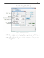
5.6.2
Overview
This Windows software application has advanced auto-discovery feature which
automatically finds computer connected Picomotor controllers and list them in the “Device
Tree” window. So called ‘Slave’ controllers (devices) connected via RS-485 LAN are
listed immediately underneath and shifted to the right of ‘Master’ controllers which have
direct computer connection. The user can then select the controller to operate. Also, near
the upper right area of the application the user can select which specific motor (1, 2, 3 or
4) to control.
NOTE: In the device tree window, the software will show the address (1-31) to the
right of each controller’s model number/serial number information in
parenthesis only when controllers are connected together via RS-485 LAN.
Figure 28
Controller Address Identification
At the bottom of the application is a “Message” window where application and controller
generated messages are shown (e.g., error messages, status).
Additionally, at the very bottom of the application is a connection status indicator which
lets the user know when the application is actively communicating with a controller.
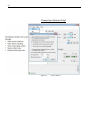
There are three(3) main application views or tabs: (1) Jog tab, (2) Cycle tab, and (3)
Terminal tab.
The Jog tab allows a user to “Jog” a motor forward or backward in predefined “Relative”
displacements or in “Free Run” (continuous) moves, depending on mode selected. In this
tab view one can also move to an target position.
In the Cycle tab, a user can enter two target position destinations to have the Picomotor
cycle between these two points with programmable dwell time between stops and optional
number of cycles limit.
The Terminal tab allows users familiar with the controller’s native ASCII commands and
syntax to manually type and send commands to the controller, thereby offering maximum
flexibility and control.
Additionally, there are File, View, Setup, and Help menus selections at the top of
application screen.
50
Most notably the Setup/Controller menu selection allows the user to set motor velocity,
acceleration, and motor type for each axis. The parameters shown on the pop-up window
represent the settings read from the controller’s memory. Clicking ‘Apply’ button will
immediately send the updated parameters to the controller and save them in its nonvolatile memory. The ‘OK’ buttons does the same action as ‘Apply’ plus it then closes the
Setup window.
Jog Motion and General Overview
Figure 29
Jog Tab
NOTE: The Closed-Loop button will toggle between “Enable Closed-Loop” and “Disable
Closed-Loop” functions depending on the present motor control state.
NOTE: Closed-loop correction is automatically disabled after a controller reset, powerup condition, or motor Following Error (see FE command). The user can enable
closed-loop mode by issuing an MM command or by clicking the Enable ClosedLoop button in the Windows software application.
51
Cycle Motion
Figure 30
Cycle Tab
52
Command Line Terminal
Figure 31
Terminal Tab
53
Find Home
Figure 32
5.6.3
Home Tab
Homing Methods
The 8743-CL closed-loop controller supports three(3) methods of Homing a Picomotor
positioner: (1) Find Home, (2) Find Index, and (3) Find Travel Limit. Which methods can be
used depends primarily on what compatible signals are made available on your Picomotor
positioners (i.e., Home signal, Index signal and/or Limit signal).
In general, the HOME Search routine is a sequence of motion segments through which the
controller determines the exact location of a home (origin), index, or limit switch.
54
5.6.3.1
Find Home
The Find Home function (see OR command) moves to find the positioner’s Home signal. The
controller executes a unique sequence of motion in order to locate and finally stop the
positioner at a repeatable position. The repeatability precision will depend mostly on the
repeatability of the Home switch itself. It is not unusual for a Home only signal (with no
Index) to be repeatable to within 20 encoder counts (e.g., 8310-V actuator).
The Home signal state (High or Low) at the time the Find Home command is received tells the
controller which direction to first move toward in order to find the signal transition.
NOTE: The Find Home function is compatible with 8310-V Picomotor positioner.
5.6.3.2
Find Index
The Find Index function (see MZ command) moves to find the positioner’s next Index signal.
The controller executes a unique sequence of motion in order to locate and finally stop the
positioner at a repeatable position. The repeatability precision will depend mostly on the
repeatability of the Index signal. It is not unusual for an Index signal to be repeatable to within
4 encoder counts (e.g., 8410 rotary stage).
The Index signal is a momentary pulse captured during motion. Unlike with Find Home, the
Find Index function requires that the user tell the controller which direction to travel in order to
find the next Index signal pulse.
NOTE: The Find Index function is compatible with 8410 Picomotor rotary positioner.
5.6.3.3
Find Limit
The Find Limit function (see MT command) moves to find the positioner’s travel limit. The
controller executes a unique sequence of motion in order to locate and finally stop the
positioner at a repeatable limit position. The repeatability precision will depend mostly on the
repeatability of the limit switch itself. It is not unusual for a Limit signal to be repeatable to
within 20 encoder counts (e.g., 8310 and 8310-V actuators).
Positioners with Limit signals typically have a negative and positive travel limit. Hence, the
Find Limit function requires that the user tell the controller which limit (positive or negative) to
find so the controller can move in that direction.
NOTE: The Find Limit function is compatible with 8310 and 8310-V positioners.
COMMAND
DESCRIPTION
OR
Set controller address
MT
Controller address query
MZ
Initiate scan process
Table 4
Homing Related Commands
55
Controller Setup (Closed-Loop)
Figure 33
Setup Window (Closed-Loop)
NOTE: When controlling a standard open-loop Picomotor positioner (1) set ‘Units’ option to
‘Steps’ and (2) disable (uncheck ‘Enable’) ‘Travel Limit Checking.’
NOTE: The Travel Limit Checking feature should be disabled when controlling the 8410
rotary positioner.
56
Connection Options Setup
Figure 34
Options Window
57
USB and Ethernet Properties
Figure 35
Properties Window
58
Scan RS-485 LAN
Figure 36
Controller Scan
59
Address Conflict Resolution
Figure 37
Address Conflict Resolution Window
60
View/Change Controller Address
Figure 38
Device Address Window
61
5.6.4
Embedded Dynamic HTTP Server
It is also possible to communicate to the controller via its Ethernet interface through a
computer’s web browser (e.g., Safari, Chrome, Internet Explorer). Once you know the
controller’s IP address, which can be gotten from the Ethernet Properties view in the
Windows Application (see previous page). Enter the IP address in the browser’s address
bar and this will take you to the controller’s HTTP server page.
This advanced controller has an embedded HTTP server which generates a dynamic Web
page to accept command line input and show immediate response.
Embedded Dynamic HTTP Server
Chrome Browser (v22) running on Windows 7
Figure 39
Internet Browser View
62
5.7
LabVIEWTM and C# Programming Support
Detailed LabVIEW and C# programming instructions are discussed in a separate
document named “Picomotor Samples.pdf” (Typically installed in the following folder
C:\Program Files\New Focus\Picomotor Application\Docs)
Additionally, sample code is found in the “Samples” folder (Typically installed in the
following folder C:\Program Files\New Focus\Picomotor Application\Samples)
5.7.1
Introduction
The programming samples are divided into two folders: C# and LabVIEW. These
two folders contain samples that have been developed in the C# programming
language and the LabVIEW programming language.
63
6
Remote Command Set
6.1
Command Syntax
The 8743-CL Controller/Driver utilizes an ASCII command set and also outputs system
status in ASCII format. Commands may be either upper or lower case characters.
The diagram below illustrates the 8743-CL controller command syntax. As indicated in
this diagram, a valid command consists of three main fields. The first field consists of a
numerical parameter “xx”, the second field consists of a two letter ASCII mnemonic, and
the third field consists of numerical parameter “nn”. The command is finally terminated
by a carriage return. For example, 3PA10 is a valid command.
If a command does not require parameter “xx” and/or parameter “nn”, that field may be
skipped by leaving a blank character (space). For example, 1DH, and VE? are valid
commands.
Multiple commands can be issued on a single command line by separating the commands
with a semi-colon (;). For example, “3VA1500; 3PA1000” is a valid command line. If a
command line has multiple query commands, the response string from the controller will
have responses to all the query commands in the command line. Each response in the
response string will be separated by a semi-colon. For example, the response to “3VA?;
3AC?” command can be “2000; 30000”. In this example, the value 2000 is a response to
3VA? command, and the value 30000 is a response to 3AC? command.
Figure 40
Command Syntax Diagram
64
6.1.1
RS-485 Command Syntax
The command syntax for communicating with controllers on an RS-485 network is very
similar to communicating with them directly using USB/Ethernet interface with the
following exceptions:
1.
All the commands intended for a slave controller must have a slave controller
address prefix added to the command. For example, to query the motion status
of motor 2 on a slave controller with address 3, the host PC must send
“3>2MD?” command to the master controller. In this command, “3>” is the
slave controller address prefix. This prefix tells the master controller that the
command “2MD?” is intended for slave controller with address 3.
2. When the master controller sends a response back to host PC, it too will have a
slave controller address prefix. This is used to inform the host that the
response came from a slave controller with that address. For example, the
response received by a host PC to the above mentioned command might be
“3>1”. This indicates that the motion of motor #2 in slave controller with
address 3 is complete.
3. If a command does not have controller address prefix, the master controller will
assume that the command is addressed it and process the same.
4. Since the master controller processes one command string at a time, semicolon
(‘;’) delimited commands cannot be sent to slave controllers.
NOTE
A controller command (or a sequence of commands) has to be terminated with a
carriage return character. However, responses from the controller are always
terminated by a carriage return/line feed combination. This setting may not be
changed.
65
6.1.2
Summary of Command Syntax
COMMAND FORMAT
The general format of a command is a two character mnemonic (AA). Both upper and
lower case are accepted. Depending on the command, it could also have optional or
required preceding (xx) and/or following (nn) parameters.
BLANK SPACES
Blank spaces are allowed and ignored between parameters and commands. For the clarity
of the program and memory saving considerations, use blank spaces with restraint. The
following two commands are equivalent.
2 PA 1000
2PA1000
COMMAND LINE
Commands are executed line by line. A line can consist of one or a number of commands.
The controller will interpret the commands in the order they are received and execute them
sequentially. This means that commands issued on the same line are executed
significantly closer to each other than if they would be issued on separate lines. The
maximum number of characters allowed on a command line is 64.
SEPARATOR
Commands issued on the same line must be separated by semicolons (;).
Multiple parameters issued for the same command are separated by commas (,).
TERMINATOR
Each command line must end with a line terminator, i.e., carriage return.
66
6.2
Command List
The controller understands many commands. The following table lists all of them in
alphabetical order. It also shows whether the command can be issued while motion of any
Picomotor is in progress or otherwise.
Command
Description
Command executed when
motion is in progress
*IDN?
Identification string query
*RCL
Recall parameters
*RST
Reset instrument
AB
Abort motion
AC
Set acceleration
AC?
Get acceleration
CL
Set closed-loop update interval
CL?
Get closed-loop update interval
DB
Set deadband
DB?
Get deadband
DH
DH?
Get home position
Set following error limit
FE?
Get following error limit
MC
Motor check
MD?
Get motion done status
MM
Enable closed-loop control
Get closed-loop control status
MT
Find travel limit position
MV
Move indefinitely
MV?
Define home position
FE
MM?
Get motion direction
MZ
Find index position
OR
Find home position
PA
Move to a target position
PA?
Get destination position
PH?
Get hardware status
PR
PR?
Move relative
Get destination position
67
QM
Set motor type
QM?
Get motor type
RS
Reset the controller
SA
Set controller address
SA?
Get controller address
SC
Scan RS-485 network
SC?
Get RS-485 network controller
addresses
SD?
Get scan status
SM
Save to non-volatile memory
SN
Set units
SN?
Get units
Stop motion
TB?
Get error message
TE?
Get error number
TP?
Get position
VA
Set velocity
VA?
Get velocity
VE?
Firmware version string query
ST
XX
Purge memory
ZH
Set hardware configuration
ZH?
Get hardware configuration
ZZ
Set configuration register
ZZ?
Get configuration register
ETHERNET RELATED COMMANDS
Command
Description
GATEWAY
Default gateway address
GATEWAY?
Default gateway address query
HOSTNAME
Hostname
Hostname query
IP address
HOSTNAME?
IPADDR
Command executed
when motion is in
progress
68
IPADDR?
IP address query
IPMODE
IP mode
IP mode query
MAC address query
Network mask address
Network mask address query
IPMODE?
MACADDR?
NETMASK
NETMASK?
CLOSED-LOOP RELATED COMMANDS
Command
Description
CL
Set closed-loop update interval
CL?
Get closed-loop update interval
DB
Set deadband
DB?
Get deadband
FE
Set following error limit
FE?
Get following error limit
MM
Enable closed-loop control
MM?
Get closed-loop control status
SN
Set units
SN?
Get units
ZH
Set hardware configuration
ZH?
Get hardware configuration
Command executed
when motion is in
progress
HOMING RELATED COMMANDS
Command
Description
MT
Find travel limit position
MZ
Find index position
OR
Find home position
PH?
Get hardware status
ZH
Set hardware configuration
ZH?
Get hardware configuration
Command executed
when motion is in
progress
69
6.2.1
Description of Commands
NOTE
Many of the commands take an axis number as a parameter (xx). For such
commands, the valid range of axis number is from 1 to 2.
*IDN?
Description
Product identification string query.
Syntax
*IDN?
Remarks
This query will cause the instrument to return a unique identification string. This similar to the
Version (VE) command but provides more information. In response to this command the
controller replies with company name, product model name, firmware version number,
firmware build date, and controller serial number. No two controllers share the same model
name and serial numbers, therefore this information can be used to uniquely identify a specific
controller.
Model
Name
Firmware
Version #
Firmware
Date
Controller
Serial #
New_Focus XXXX vYYY mm/dd/yy, SNZZZZ
Example
*IDN?
New_Focus 8743-CL v1.9 10/23/12 SN10001
See Also
VE?
(Get product identification information)
(Controller replies with ID string)
70
*RCL
Description
Recall command.
Syntax
*RCL Bin
Remarks
This command restores the controller working parameters from values saved in its non-volatile
memory. It is useful when, for example, the user has been exploring and changing parameters
(e.g., velocity) but then chooses to reload from previously stored, qualified settings. Note that
“*RCL 0” command just restores the working parameters to factory default settings. It does not
change the settings saved in EEPROM.
The parameters that can be restored are:
1. Hostname (see HOSTNAME command)
2. IP Mode (see IPMODE command)
3. IP Address (see IPADDRESS command)
4. Subnet mask address (see NETMASK command)
5. Gateway address (see GATEWAY command)
6. Configuration register (see ZZ command)
7. Motor type (see QM command)
8. Desired Velocity (see VA command)
9. Desired Acceleration (see AC command)
Argument
Bin
Value
0
1
Description
Restores factory default settings
Restores last saved settings
Example
*RCL1
(Restore from last saved settings)
See Also
SM, XX
71
*RST
Description
Reset command.
Syntax
*RST
Remarks
This command performs a “soft” reset or reboot of the controller CPU. Upon restart the
controller reloads parameters (e.g., velocity and acceleration) last saved in non-volatile
memory.
Note that upon executing this command, USB and Ethernet communication will be interrupted
for a few seconds while the controller re-initializes. Ethernet communication may be
significantly delayed (~30 seconds) in reconnecting depending on connection mode (Peer-topeer, static or dynamic IP mode) as the PC and controller are negotiating TCP/IP
communication.
See Also
RS
AB
Description
Abort motion.
Syntax
AB
Remarks
This command is used to instantaneously stop any motion that is in progress. Motion is
stopped abruptly. For stop with deceleration see ST command which uses programmable
acceleration/deceleration setting.
Example
1MV+
AB
See Also
ST
(Move motor 1 indefinitely in positive direction)
(Abort /halt motion)
72
AC
Description
Acceleration set.
Syntax
xxACnn
Remarks
This command is used to set the acceleration value for an axis. The acceleration setting
specified will not have any effect on a move that is already in progress. If this command is
issued when an axis’ motion is in progress, the controller will accept the new value but it will
use it for subsequent moves only.
Argument
xx
nn
Example
2AC150000
See Also
AC?, VA, VA?
Value
1 to 2
1 to 200000
Description
Axis number
2
2
Acceleration (steps/sec ). Default = 100000 steps/sec
(set acceleration to 150,000 steps/sec2)
AC?
Description
Acceleration query.
Syntax
xxAC?
Remarks
This command is used to query the acceleration value for an axis.
Argument
xx
Value
1 to 2
Description
Axis number
Response
Value
Value
Integer
Description
2
Acceleration setting (steps/sec )
Example
2AC?
150000
(get acceleration setting)
(reply; 150,000 steps/sec2)
See Also
AC, VA, VA?
73
CL
Description
Closed-loop control update interval set.
Syntax
xxCLnn
Remarks
This command is used to set the closed-loop control update interval for an axis. This will be
the time duration between position error corrections during closed-loop positioning.
For maximum user application flexibility, each axis is allowed to have a different and
independent time interval setting from one another.
Position error corrections occur only during position regulation (holding position) as opposed to
while moving.
NOTE: Motor positioning units must be in ‘Counts’ (see SN command) and closed-loop
mode enabled (see MM command) for CL command setting to take effect.
Argument
xx
nn
Value
1 to 2
0.1 to 100000
Description
Axis number
Update interval (sec). Default = 0.1 sec
Example
1CL60
2CL1
SM
(set motor 1 closed-loop update interval to 60 seconds)
(set motor 2 closed-loop update interval to 1 second)
(save to non-volatile memory)
See Also
CL?, MM, FE, SN
CL?
Description
Closed-loop control update interval query.
Syntax
xxCL?
Remarks
This command is used to query the closed-loop control update interval for an axis.
Argument
xx
Value
1 to 2
Description
Axis number
Response
Value
Value
Integer
Description
Update interval (sec)
Example
2CL?
1
(get closed-loop control update interval setting)
(reply; 1 sec)
See Also
CL, MM, FE, SN
74
DB
Description
Deadband set.
Syntax
xxDBnn
Remarks
This command is used to set the position deadband value for an axis. Since a majority of
electro-mechanical systems have mechanical backlash or frictional hysteresis, closed-loop
positioning can at times lead to oscillation or limit cycling of the systems around a desired
position. In such situations, setting position deadband value judiciously can avoid limit cycling
of the systems.
Note that this command is effective only during position regulation (holding position) as
opposed to while moving. Also, the positioning units must be in ‘Counts’ (see SN command)
and closed-loop positioning must be enabled (see MM command) for DB command to take
effect.
NOTE: An error will be generated if the controller makes more than 100 consecutive
unsuccessful attempts to correct the stage position, but is unable to bring the
following error to within specified deadband setting.
Example
See Also
Argument
xx
nn
Value
1 to 2
0 to 2147483647
2DB0
(set deadband value to 0 encoder counts)
2SN1
2FE1000
2CL0.1
SM
2MM1
2PA+100
(set units to encoder counts)
(set following error threshold to 1000 counts)
(set closed-loop update interval to 0.1 second)
(save settings to non-volatile memory)
(enable closed-loop positioning)
(move to encoder count position +100)
DB?, SN, MM, FE, CL
Description
Axis number
Deadband value (units). Default = 0
75
DB?
Description
Deadband query.
Syntax
xxDB?
Remarks
This command is used to query the deadband value for an axis.
Argument
xx
Value
1 to 2
Description
Axis number
Response
Value
Value
Integer
Description
Deadband (units)
Example
2DB?
0
(get deadband setting)
(reply; 0 counts)
See Also
DB, CL, CL?, MM, MM?
76
DH
Description
Home position set.
Syntax
xxDHnn
Remarks
This command is used to define the “home” position for an axis. The home position is set to 0 if
this command is issued without “nn” value. Upon receipt of this command, the controller will set
the present position to the specified home position. The move to absolute position command
(PA) uses the “home” position as reference point for moves.
Argument
xx
nn
Value
1 to 2
Integer
Description
Axis number
Home position (steps). Default = 0 steps. Valid values
between -2147483648 and +2147483647.
Example
1DH
2DH1000
(set motor 1 counter to 0)
(set motor 2 counter equal to 1000)
See Also
DH?, TP?, PA, OR, MT, MZ
DH?
Description
Home position query.
Syntax
xxDH?
Remarks
This command is used to query the home position value for an axis.
Argument
xx
Value
1 to 2
Description
Axis number
Response
Value
Value
Integer
Description
Home position setting (steps)
Example
2DH?
0
(get home position)
(reply; home position is 0)
See Also
DH, TP?
77
FE
Description
Maximum following error threshold set.
Syntax
xxFEnn
Remarks
This command is used to set the maximum allowed following (tracking) error threshold for an
axis. This error is defined as the difference between the real (encoder) position and destination
(target) position of a motion device. The real position is the one reported by the position
sensing device (i.e., quadrature encoder).
If following error checking is enabled (see ZH command) and the following error exceeds the
maximum threshold specified with this command, the controller will automatically disable
closed-loop positioning (see MM command). Also, the positioning units must be set to
‘Counts’ in order for following error tracking and closed-loop correction to take effect (see SN
command).
NOTE: Following error checking must be enabled (see ZH command) in order for FE
command to take effect.
Argument
xx
nn
Value
1 to 2
0 to 2147483647
Description
Axis number
Following error value (units). Default = 1000
Example
2SN1
2FE1000
2CL0.1
2ZH0
SM
(set units to ‘Counts’; encoder monitoring)
(set following error threshold to 1000 counts)
(set closed-loop update interval to 0.1 second)
(enable travel limit checking and following error checking)
(save settings to non-volatile memory)
See Also
FE?, SN, SN?, MM, ZH
78
FE?
Description
Maximum following error threshold query.
Syntax
xxDB?
Remarks
This command is used to query the following error threshold value for an axis.
Argument
xx
Value
1 to 2
Description
Axis number
Response
Value
Value
Integer
Description
Following error (units)
Example
2FE?
1000
(get following error setting)
(reply; 1000 counts)
See Also
FE, CL, CL?, MM, MM?
MC
Description
Motor check command
Syntax
MC
Remarks
This command scans for motors connected to the controller, and sets the motor type based on
its findings. If the piezo motor is found to be type ‘Tiny’ then velocity (VA) setting is
automatically reduced to 1750 if previously set above 1750. To accomplish this task, the
controller commands each axis to make a one-step move in the negative direction followed by a
similar step in the positive direction. This process is repeated for all the four axes starting with
the first one. If this command is issued when an axis is moving, the controller will generate
“MOTION IN PROGRESS” error message.
NOTE: Motor type and velocity changes are NOT automatically saved to non-volatile
memory. Issue the Save (SM) command after motor check to save all changes.
Example
MC
SM
See Also
*RST, VA, SM
(check all motors to determine type)
(save new settings to memory)
79
MD?
Description
Motion done status query.
Syntax
xxMD?
Remarks
This command is used to query the motion status for an axis.
Note that since this product implements a multiplexed driver architecture, it is recommended
that each axis be checked for its motion done status to definitively determine if it is OK to issue
a move command to that motor. That is because, for example, although motor 1 move is done
(1MD?=0) it still would not be available for a new move command if, say, motor 2 is moving
(2MD?=1).
The MD command can be used to monitor motion done status for the following commands: PR,
PA, MV, OR, MT, MZ
Argument
xx
Value
1 to 2
Description
Axis number
Response
Value
Value
0
1
Description
Motion is in progress
Motion is not in progress
Example
2MD?
1
(get motor 2 motion status)
(returns value of 1 which means motor 2 is moving)
See Also
TP?, PA, PR, OR, MZ, MT, MV
80
MM
Description
Enable/disable closed-loop positioning.
Syntax
xxMMnn
Remarks
This command is used to enable/disable closed-loop positioning of an axis. If closed-loop
positioning is disabled, Picomotors can be commanded to move, but the controller will not
perform any end of move position correction. Closed-Loop correction takes affect only during
position regulation (holding position) as opposed to while moving. Furthermore, the
positioning units must be in ‘Counts’ (see SN command
NOTE: Closed-Loop correction is automatically disabled (MM=0) after a controller reset,
power-up, or a Following Error condition (see FE command).
Example
See Also
Argument
xx
nn
Value
1 to 2
0
1
Description
Axis number
Disable closed-loop positioning. Default = 0
Enable closed-loop positioning
2SN1
2FE1000
2CL0.1
SM
(set units to ‘Counts’; encoder monitoring)
(set following error threshold to 1000 counts)
(set closed-loop update interval to 0.1 second)
(save settings to non-volatile memory)
2MM1
2PA+100
(enable closed-loop positioning)
(move to encoder count position +100)
MM?, SN, FE, CL
MM?
Description
Closed-loop positioning status query.
Syntax
xxDB?
Remarks
This command is used to query the closed-loop positioning status for an axis.
Argument
xx
Value
1 to 2
Description
Axis number
Response
Value
Value
0 or 1
Description
Disable or Enable
Example
2MM?
0
(get closed-loop positioning status)
(reply; 0; closed-loop positioning presently disabled)
See Also
MM
81
MT
Description
Find hardware travel limit.
Syntax
xxMTnn
Remarks
This command is used to move an axis to its limit (positive or negative). The controller will
automatically stop the axis after crossing the travel limit. If this command is issued when an
axis’ motion is in progress, the controller will ignore this command and generate “MOTION IN
PROGRESS” error message.
The controller executes a unique sequence of motion in order to locate and finally stop the
positioner at a repeatable limit position. The repeatability precision depends mostly on the
repeatability of the limit switch itself and ability to stop and hold final position. It is not
unusual for a Limit signal to be repeatable to within 20 encoder counts (e.g., 8310 and 8310-V
actuators).
Positioners with Limit signals typically have a negative and positive travel limit. Hence, the
Find Limit function requires that the user tell the controller which limit (positive or negative) to
find so the controller can move in that direction.
The MT motion status can be monitored using the Motion Done (MD?) command.
NOTE: The controller will NOT stop motion until it finds the travel limit. Send the Stop
(ST) or Abort (AB) motion command to terminate motion.
NOTE: Travel limit signal checking should first be enabled (see ZH command) before
Find Limit (MT) command is issued. Otherwise, error x35 will be generated.
NOTE: MT is compatible with 8310 and 8310-V positioners as each model outputs travel
limit signals. However, MT command is NOT compatible with 8410 rotary stage.
Example
See Also
Argument
xx
nn
Value
1 to 2
+
-
1ZH0
(enable motor 1 travel limit checking and following error checking)
1MT+
AB
2ZH0
2MT2MD?
2DH
(find motor 1 travel limit in positive direction)
(abort / halt motion)
(enable motor 2 travel limit checking and following error checking)
(find motor 2 travel limit in negative direction)
(get move done status)
(when move done, zero the counter at limit position)
MV, MZ, OR, ST, AB, ZH
Description
Axis number
Travel limit search of desired axis in positive direction
Travel limit search desired axis in negative direction
82
MV
Description
Indefinite move command.
Syntax
xxMVnn
Remarks
This command is used to move an axis indefinitely. If this command is issued when an axis’
motion is in progress, the controller will ignore this command and generate “MOTION IN
PROGRESS” error message.
Issue a Stop (ST) or Abort (AB) motion command to terminate motion initiated by MV
Example
See Also
Argument
xx
nn
Value
1 to 2
+
-
1MV+
AB
(Move motor 1 indefinitely in positive direction)
(Abort /halt motion)
2MV2ST
(Move motor 2 indefinitely in negative direction)
(Stop motion)
PA, PR, ST, AB
Description
Axis number
Move desired axis in positive direction
Move desired axis in negative direction
83
MZ
Description
Find nearest index search.
Syntax
xxMZnn
Remarks
This command is used to move an axis to its nearest Index in positive or negative direction.
The controller will automatically stop the axis after crossing the index. If this command is
issued when an axis’ motion is in progress, the controller will ignore this command and
generate “MOTION IN PROGRESS” error message.
The controller executes a unique sequence of motion in order to locate and finally stop the
positioner at a repeatable Index position. The repeatability precision depends mostly on the
repeatability of the Index itself and ability to stop and hold final position. It is not unusual for a
Find Index function to be repeatable to within 4 encoder counts (e.g., 8410 rotary stage).
The MZ motion status can be monitored using the Motion Done (MD?) command.
NOTE: The controller will NOT stop motion until it finds the Index signal transition.
Send the Stop (ST) or Abort (AB) motion command to terminate motion.
NOTE: The Find Index function is compatible with 8410 positioner.
NOTE: The Find Index function is NOT compatible with 8310 and 8310-V positioners.
Example
Argument
xx
nn
Value
1 to 2
+
-
Description
Axis number
Index search of desired axis in positive direction
Index search desired axis in negative direction
1MZ+
AB
(index search of motor 1 in positive direction)
(abort / halt motion)
2MZ2MD?
2DH
(index search of motor 2 in negative direction)
(monitor move done status)
(when move done, zero the counter at ‘index’ position)
84
OR
Description
Find Home search.
Syntax
xxOR
Remarks
This command is used to execute a home search routine for an axis. The controller will
automatically stop the axis after crossing the index. If this command is issued when an axis’
motion is in progress, the controller will ignore this command and generate “MOTION IN
PROGRESS” error message.
The controller executes a unique sequence of motion in order to locate and finally stop the
positioner at a repeatable Home position. The repeatability precision depends mostly on the
repeatability of the Home switch itself and ability to stop and hold final position. It is not
unusual for a Find Home function to be repeatable to within 20 encoder counts (e.g., 8410-V
positioner).
Issue the Define Home (DH) command after OR completed to make Home position the
reference for Position Absolute (PA) commands.
The Home search motion status can be monitored using the Motion Done (MD?) command.
NOTE: The controller will NOT stop motion until it finds the Home signal transition.
Send the Stop (ST) or Abort (AB) motion command to terminate motion.
NOTE: The Find Home function is compatible with 8310-V positioner.
NOTE: The Find Home function is NOT compatible with 8310 and 8410 positioners.
Example
Argument
xx
Value
1 to 2
Description
Axis number
1OR
1MD?
1DH
(find motor 1 home switch)
(monitor move done status)
(when move done, zero the counter at ‘home’ position)
85
PA
Description
Target position move command.
Syntax
xxPAnn
Remarks
This command is used to move an axis to a desired target (absolute) position relative to the
home position defined by DH command. Note that DH is automatically set to 0 after controller
reset or a power cycle. If this command is issued when an axis’ motion is in progress, the
controller will ignore this command and generate “MOTION IN PROGRESS” error message.
The direction of motion and number of steps needed to complete the motion will depend on
where the motor count is presently at before the command is issued.
While operating in closed-loop mode, the Model 8743-CL will respond to motion command
displacements based upon increments of the closed-loop Picomotor positioner’s internal optical
encoder, rather than by actual Picomotor steps. The controller will automatically determine the
appropriate number of Picomotor steps needed to accomplish the target encoder counts based
displacement.
NOTE: If positioning Units are set to ‘Steps’ (SN=0) then displacements will be in terms
of Picomotor steps whereas if Units are set to ‘Counts’ then displacements will
be in terms of closed-loop Picomotor positioner encoder counts. (See SN
command)
Issue a Stop (ST) or Abort (AB) motion command to terminate motion initiated by PA
Argument
xx
nn
Value
1 to 2
Integer
Example
1PA+200000
See Also
MV, PR, DH, SN
Description
Axis number
Absolute position (steps). Default = 0 steps. Valid values
between -2147483648 and +2147483647.
(Move motor 1 to target position +200000)
86
PA?
Description
Target position query.
Syntax
xxPA?
Remarks
This command is used to query the target position of an axis.
Argument
xx
Value
1 to 2
Description
Axis number
Response
nn
Value
Integer
Description
Target position (steps).
Example
2PA?
200000
(Get motor 2 target position)
(Returns value of 200000 step target position)
See Also
MV, PR
87
PH?
Description
Hardware status query.
Syntax
PH?
Remarks
This command is used to query general hardware status for all the axes. This function allows
the user to observe the various digital input signals as they appear to the controller in real-time.
Note that the positioner’s Home or Index signals come in on the same controller differential
input pair, feedback connector pins 14 & 15. That means that if an 8410 rotary positioner is
connected then the Home/Index input actually represents ‘Index’ signal status, because that is
what the 8410 provides. However, if an 8310-V actuator is connected then the Home/Index
represents ‘Home’ signal status, because that is what the 8310-V provides.
Note that the Index signal is a momentary signal transition, a few encoder counts wide, whereas
a Home signal is typically a logical High from the middle of positioner travel range to the
positive travel limit and a logical Low from the negative travel limit to the positioner middle.
The controller treats the signal differently, as either Home or Index type, depending on whether
the OR (Find Home) or MZ (Find Index) command was issued.
Response
nn
Bit
0
1
2
3
4
5
Example
PH?
9
See Also
MT, MZ
Value
0
1
0
1
0
1
0
1
0
1
0
1
Value
Integer
Description
Decimal representation of binary number
Definition
Axis 1 positive hardware travel limit low
Axis 1 positive hardware travel limit high
Axis 1 negative hardware travel limit low
Axis 1 negative hardware travel limit high
Axis 1 home/index signal low
Axis 1 home/index signal high
Axis 2 positive hardware travel limit low
Axis 2 positive hardware travel limit high
Axis 2 negative hardware travel limit low
Axis 2 negative hardware travel limit high
Axis 2 home/index signal low
Axis 2 home/index signal high
(Get hardware status)
(Returns 9. 9 decimal is equal to 1001 in binary. This means bits 0 and 3 are
logical HIGH which also means positive hardware travel limits on axes 1 and 2
are TTL level HIGH)
88
PR
Description
Relative move command.
Syntax
xxPRnn
Remarks
This command is used to move an axis by a desired relative distance. If this command is issued
when an axis’ motion is in progress, the controller will ignore this command and generate
“MOTION IN PROGRESS” error message.
While operating in closed-loop mode, the Model 8743-CL will respond to motion command
displacements based upon increments of the closed-loop Picomotor positioner’s internal optical
encoder, rather than by actual Picomotor steps. The controller will automatically determine the
appropriate number of Picomotor steps needed to accomplish the target encoder counts based
displacement.
NOTE: If positioning Units are set to ‘Steps’ (SN=0) then displacements will be in terms
of Picomotor steps whereas if Units are set to ‘Counts’ then displacements will
be in terms of closed-loop Picomotor positioner encoder counts. (See SN
command)
Issue a Stop (ST) or Abort (AB) motion command to terminate motion initiated by PR
Argument
xx
nn
Example
1PR-200000
See Also
MV, PA, SN
Value
1 to 2
Integer
Description
Axis number
Relative distance (steps). Default = 0 steps. Valid values
between -2147483648 and +2147483647.
(Move motor 1 relative negative 200000 steps)
89
PR?
Description
Target position query.
Syntax
xxPR?
Remarks
This command is used to query the target position of an axis.
Argument
xx
Value
1 to 2
Description
Axis number
Response
nn
Value
Integer
Description
Target position (steps).
Example
2PR?
200000
(Get motor 2 target position)
(Returns value of 200000 step target position)
See Also
MV, PA, SN
90
QM
Description
Motor type set command.
Syntax
xxQMnn
Remarks
This command is used to manually set the motor type of an axis. Send the Motors Check (MC)
command to have the controller determine what motors (if any) are connected. Note that for
motor type ‘Tiny’, velocity should not exceed 1750 step/sec. To save the setting to non-volatile
memory, issue the Save (SM) command.
Note that the controller may change this setting if auto motor detection is enabled by setting bit
number 0 in the configuration register to 0 (default) wit ZZ command. When auto motor
detection is enabled the controller checks motor presence and type automatically during all
moves and updates QM status accordingly.
Argument
xx
nn
Value
1 to 2
0
1
2
3
Description
Axis number
No motor connected
Motor type unknown
‘Tiny’ Motor
‘Standard’ motor
Example
2QM3
SM
(Set motor 2 to type ‘Standard’ Picomotor)
(Save new settings to memory)
See Also
QM?, MC, ZZ, SM
91
QM?
Description
Motor type query.
Syntax
xxQM?
Remarks
This command is used to query the motor type of an axis.
It is important to note that the QM? command simply reports the present motor type setting in
memory. It does not perform a check to determine whether the setting is still valid or
corresponds with the motor connected at that instant.
If motors have been removed and reconnected to different controller channels or if this is the
first time, connecting this system then issuing the Motor Check (MC) command is
recommended. This will ensure an accurate QM? command response.
Argument
xx
Value
1 to 2
Description
Axis number
Response
nn
Value
Integer
Description
Motor type.
Example
1QM?
0
(Get motor 1 motor type setting)
(Return 0; no motor connected)
See Also
QM, CM, ZZ
RS
Description
Reset command
Syntax
RS
Remarks
This command performs a “soft” reset or reboot of the controller CPU. Upon restart the
controller reloads parameters (e.g., velocity and acceleration) last saved in non-volatile memory
and sets Home (DH) position to 0.
Note that upon executing this command, USB and Ethernet communication will be interrupted
for a few seconds while the controller re-initializes. Ethernet communication may be
significantly delayed (~30 seconds) in reconnecting depending on connection mode (Peer-topeer, static or dynamic IP mode) as the PC and controller are negotiating TCP/IP
communication.
Example
RS
See Also
*RST
(Reboot/reset controller)
92
SA
Description
Controller address set.
Syntax
SAnn
Remarks
This command is used to set the address of a controller. This command is useful when
communicating with controllers on an RS-485 network, where all controllers on the network
must have unique addresses. The default controller address is 1.
Argument
nn
Value
Integer
Description
Controller address. Default = 1. Valid values
between 1 and 31.
Example
SA5
SM
(set controller address to 5)
(save new address in controller’s memory)
See Also
SA, SC, SD?
SA?
Description
Controller address query.
Syntax
SA?
Remarks
This command is used to query the controller’s address.
Response
Value
Value
Integer
Description
Controller address
Example
SA?
5
(get controller’s address)
(reply; controller address is 5)
See Also
SA, SC, SD?
93
SC
Description
Initiate scan process.
Syntax
SCnn
Remarks
This command is used to initiate scan of controllers on RS-485 network. When a master
controller receives this command, it scans the RS-485 network for all the slave controllers
connected to it.
If nn = 0, the master controller scans the network but does not resolve any address conflicts.
If nn = 1, the master controller scans the network and resolves address conflicts, if any. This
option preserves the non-conflicting addresses and reassigns the conflicting addresses starting
with the lowest available address. For example, during an initial scan, if the master controller
determines that there are unique controllers at addresses 1,2, and 7 and more than one
controller at address 23, this option will reassign only the controllers with address conflict at 23;
the controllers with addresses 1,2, and 7 will remain untouched. In this case, after conflict
resolution, the final controller addresses might be 1,2,3,7, and 23 if the master determines that
there are two (2) controllers initially at address 23.
If nn = 2, the master controller reassigns the addresses of all controllers on the network in a
sequential order starting with master controller set to address 1. In the example mentioned
above, after reassignment of addresses, the final controller addresses will be 1,2,3,4, and 5.
Argument
nn
Value
Integer
Description
Scan option. Valid values between 0 and 2.
Example
SC0
(scan the RS-485 network but do not any address conflicts)
See Also
SA, SC?, SD?
94
SC?
Description
RS-485 controller address map query.
Syntax
SC?
Remarks
This command is used to query the list of all controllers on an RS-485 network.
Response
Value
Value
Integer
Description
32-bit value. Default = 0
Bit#
0
0
1
1
Value
0
1
0
1
Description
The scan process did not find any address conflicts
The scan process found at least one address conflicts
There is no controller with address 1 on the network
There is a controller with address 1 on the network
31
31
0
1
There is no controller with address 31 on the network
There is a controller with address 31 on the network
Bits 1—31 are one-to-one mapped to controller addresses 1—31. The bit value is set to 1 only
when there are no conflicts with that address.
For example, if the master controller determines that there are unique controllers at addresses
1,2, and 7 and more than one controller at address 23, this query will return 135. The binary
representation of 135 is 10000111. Bit #0 = 1 implies that the scan found at least one address
conflict during last scan. Bit #1,2, 7 = 1 implies that the scan found controllers with addresses
1,2, and 7 that do not conflict with any other controller.
Example
SC?
135
See Also
SA, SC, SD?
(get controller address map)
(reply; see above description)
95
SD?
Description
Scan done status query.
Syntax
SD?
Remarks
This command is used to query the scan status.
Response
Value
Value
0
1
Description
Scan is in progress
Scan is not in progress
Example
SD?
1
(Get scan status)
(Returns value of 1 which means scan is not in progress)
See Also
SC, SC?
96
SM
Description
Save settings command
Syntax
SM
Remarks
This command saves the controller settings in its non-volatile memory. The controller restores
or reloads these settings to working registers automatically after controller reset or it reboots.
The Purge (XX) command is used to clear non-volatile memory and restore to factory settings.
Note that the SM saves parameters for all motors.
The SM command saves the following settings:
1. Hostname (see HOSTNAME command)
2. IP Mode (see IPMODE command)
3. IP Address (see IPADDRESS command)
4. Subnet mask address (see NETMASK command)
5. Gateway address (see GATEWAY command)
6. Configuration register (see ZZ command)
7. Motor type (see QM command)
8. Desired Velocity (see VA command)
9. Desired Acceleration (see AC command)
10. Closed-Loop interval (see CL command)
11. Deadband (see DB command)
12. Following Error (see FE command)
13. Units (see SN commands)
14. Hardware Configuration (see ZH command)
Example
See Also
1VA1750
(See motor 1 velocity)
SM
(Save settings to non-volatile memory)
XX, *RCL
97
SN
Description
Axis displacement units set.
Syntax
xxSNnn
Remarks
This command is used to set the displacement units of an axis.
The inherent Picomotor positioner operates in steps and is open-loop. However, when a
quadrature encoder is integrated into a Picomotor positioner and those signals are brought to the
controller’s feedback connector then it is possible to monitor real position using encoder
‘Counts’. The use of ‘Counts’ as positioning units makes possible closed-loop control.
However, when the control is set to use ‘Steps’ as positioning units then only open-loop control
is possible.
NOTE: If units set to ‘Steps’ (SN=0) then only open-loop positioning is possible.
Example
See Also
Argument
xx
nn
Value
1 to 2
0
1
1SN0
(set displacement units to steps)
2SN1
(set displacement units to encoder counts)
SN?, CL, FE, MM, DB
Description
Axis number
Units are steps (open-loop mode).
Units are encoder counts. Default = 1
98
SN?
Description
Axis displacement units query.
Syntax
xxSN?
Remarks
This command is used to query the displacement units for an axis.
Argument
xx
Value
1 to 2
Description
Axis number
Response
Value
Value
0 or 1
Description
Steps or Encoder counts
Example
2SN?
1
(get displacement units)
(reply; 1)
See Also
SN
99
ST
Description
Stop motion command
Syntax
xxST
Remarks
This command is used to stop the motion of an axis. The controller uses acceleration specified
using AC command to stop motion. If no axis number is specified, the controller stops the axis
that is currently moving. Use Abort (AB) command to abruptly stop motion without
deceleration.
Example
See Also
Argument
xx
Value
1 to 2
1MV+
1ST
(Move motor 1 indefinitely in positive direction)
(Stop motion)
ST
(Stop motion on any motor that is moving)
AB, AC
Description
Axis number
100
TB?
Description
Error message query
Syntax
TB?
Remarks
This command is used to read the error code, and the associated message.
The error code is one numerical value up to three(3) digits long. (see Appendix for
complete listing) In general, non-axis specific errors numbers range from 0-99. Axis-1
specific errors range from 100-199, Axis-2 errors range from 200-299 and so on. The
message is a description of the error associated with it. All arguments are separated by
commas.
Note: Errors are maintained in a FIFO buffer ten(10) elements deep. When an error is
read using TB or TE, the controller returns the last error that occurred and the error
buffer is cleared by one(1) element. This means that an error can be read only once,
with either command.
Response
nn, ssss
Example
See Also
Value
integer, string
Description
Error code, Error message
TB?
108, MOTOR NOT CONNECTED
(Get error status)
(Returns motor 1 not connected error message)
TB?
0, NO ERROR DETECTED
(Get error status)
(Returns no error found message)
TE
101
TE?
Description
Error code query
Syntax
TE?
Remarks
This command is used to read the error code. The error code is one numerical value up
to three(3) digits long. (see Appendix for complete listing) In general, non-axis specific
errors numbers range from 0-99. Axis-1 specific errors range from 100-199, Axis-2
errors range from 200-299 and so on.
Note: Errors are maintained in a FIFO buffer ten(10) elements deep. When an error is
read using TB or TE, the controller returns the last error that occurred and the error
buffer is cleared by one(1) element. This means that an error can be read only once,
with either command.
Example
See Also
Response
nn
Value
integer
TE?
108
(Get error status)
(Returns 108; motor 1 not connected)
TE?
0
(Get error status)
(Returns 0; no error detected)
TB
Description
Error code
102
TP?
Description
Actual Position query.
Syntax
xxTP?
Remarks
This command is used to query the actual position of an axis. The actual position represents the
internal number of steps made by the controller relative to its position when controller was
powered ON or a system reset occurred or Home (DH) command was received.
Note that the real or physical position of the actuator/motor may differ as a function of
mechanical precision and inherent positioning inaccuracies.
NOTE: TP response value could either represent encoder ‘Counts’ or open-loop ‘Steps’
depending on Units setting (see SN command).
Argument
xx
Value
1 to 2
Description
Axis number
Response
nn
Value
Integer
Description
Present position (steps)
Example
1TP?
10500
(Get motor 1 position status)
(Returns 10500; motor 1 position)
See Also
PA, PR, MV, DH, SN
103
VA
Description
Velocity set
Syntax
xxVAnn
Remarks
This command is used to set the velocity value for an axis. The velocity setting specified will
not have any effect on a move that is already in progress. If this command is issued when an
axis’ motion is in progress, the controller will accept the new value but it will use it for
subsequent moves only. The maximum velocity for a ‘Standard’ Picomotor is 2000 steps/sec,
while the same for a ‘Tiny’ Picomotor is 1750 steps/sec.
Argument
xx
nn
Value
1 to 2
1 to 2000
Description
Axis number
Velocity (steps/sec). Default = 2000 steps/sec
Example
1VA1750
(Set motor 1 velocity to 1750 steps/sec)
See Also
VA?, AC, AC?
VA?
Description
Velocity query.
Syntax
xxVA?
Remarks
This command is used to query the velocity value for an axis.
Argument
xx
Value
1 to 2
Description
Axis number
Response
Value
Value
Integer
Description
Velocity setting (steps/sec)
Example
1VA?
1750
(Get motor 1 velocity)
(Returns 1750; motor 1 velocity)
See Also
VA, AC, AC?
104
VE?
Description
Controller firmware version query.
Syntax
VE?
Remarks
This command is used to query the controller model number and firmware version. To query
product serial number information see *IDN command.
Response
ss
Example
Value
String
VE
8743-CL Version 1.9 11/01/12
See Also
Description
8743-CL Version 1.9 11/01/12
version = 1.; release date = 11/01/12
(Get model name and firmware version)
(Replies with model and firmware info string)
*IDN?
XX
Description
Purge all user settings in controller memory.
Syntax
XX
Remarks
This command is used to purge all user settings in the controller non-volatile memory and
restore them to factory default settings.
The following parameters are affected by this command:
1. Hostname (see HOSTNAME command)
2. IP Mode (see IPMODE command)
3. IP Address (see IPADDRESS command)
4. Subnet mask address (see NETMASK command)
5. Gateway address (see GATEWAY command)
6. Configuration register (see ZZ command)
7. Motor type (see QM command)
8. Desired Velocity (see VA command)
9. Desired Acceleration (see AC command)
10. Closed-Loop interval (see CL command)
11. Deadband (see DB command)
12. Following Error (see FE command)
13. Units (see SN commands)
14. Hardware Configuration (see ZH command)
Example
XX
See Also
*RCL
(Purge all user settings)
105
ZH
Description
Hardware configuration set.
Syntax
xxZHnn
Remarks
This command is used to set the hardware configuration of an axis.
The real-time status of hardware travel limit signals can be monitored using the PH command.
If hardware travel limit checking is disabled then MT (Find Limit) command is NOT allowed.
If the following error checking is disabled then the FE command setting is effectively ignored.
NOTE: When controlling a standard open-loop Picomotor positioner (1) set
‘Units’ option to ‘Steps’ and (2) disable ‘Travel Limit Checking.’
NOTE: The Travel Limit Checking feature should be disabled when controlling
the 8410 rotary positioner.
Argument
xx
nn
Bit
0
1
Value
0
1
0
1
Value
Description
1 to 2
Axis number
see table below
Definition
Enable hardware travel limit checking
Disable hardware travel limit checking
Enable following error checking
Disable following error checking
Example
2ZH1
(disable motor 2 hardware travel checking)
See Also
ZH?, CL, FE, MT, DB, PH
106
ZH?
Description
Hardware configuration query.
Syntax
xxZH?
Remarks
This command is used to query the hardware configuration for an axis.
Argument
xx
Value
1 to 2
Response
Value
Value
Description
see table below
Bit
0
1
Value
0
1
0
1
Description
Axis number
Definition
Enable hardware travel limit checking
Disable hardware travel limit checking
Enable following error checking
Disable following error checking
Example
2ZH?
2
(get hardware configuration for axis 2)
(reply; 2 decimal is equal to 10 in binary. This means bit #1 is set and bit #0 is
cleared. This implies that the controller is commanded to check for hardware
travel limits, but following error checking is disabled.)
See Also
ZH, CL, FE, MT, DB, PH
107
ZZ
Description
Configuration register set
Syntax
ZZnn
Remarks
This command is used to configure the default behavior of some of the controller’s features. It
is typically followed with an SM (Save to Memory) command.
Bit#
*0
Value
0
Description
Perform auto motor detection. Check and set motor type automatically
when commanded to move.
0
1
Do not perform auto motor detection on move
*1
0
Do not scan for motors connected to controllers upon reboot
(Performs ‘MC’ command upon power-up, reset or reboot)
1
1
Scan for motors connected to controller upon power-up or reset
Example:
ZZ 1; SM
ZZ 3; SM
See Also
*RCL, MC
(Disable automatic motor check and save to memory)
(Disable motor check on move, check motors on system reset)
ZZ?
Description
Configuration register query.
Syntax
ZZ?
Remarks
This command is used to query the configuration register setting.
Response
nn
Example:
ZZ ?
1
See Also
ZZ
Value
Integer
Description
Configuration register.
(Get configuration register settings)
(Returns 1; bit-0=1 & bit-1=0; means auto motor detection on move is disabled)
108
ETHERNET RELATED COMMANDS
GATEWAY
Description
Default gateway address set.
Syntax
GATEWAY address
Remarks
This command is used to set the Ethernet default gateway address. In order for this setting to
take effect, please set the controller to Static IP mode (IPMODE), save (SM) this parameter in
the controller’s non-volatile memory, and reset (RS) the controller.
NOTE: Send this command via USB interface as Ethernet communication may become
unstable during Ethernet settings configuration. While connected via USB, use
the Picomotor application software to send commands (Go to ‘Terminal’ tab).
Argument
address
Example:
See Also
Value
nn1.nn2.nn3.nn4
IPMODE 0
GATEWAY 192.168.10.101
NETMASK 192.168.255.0
IPADDR 192.168.1.101
SM; RS
Description
Gateway address. (Example. 192.168.10.101)
nn1,nn2,nn3,nn4 can be numbers between 0 and 255.
(Set to static IP mode)
(Set gateway address)
(Set Netmask address)
(Set IP address)
(Save and reset system)
IPMODE, SM, RS
GATEWAY?
Description
Default gateway address query.
Syntax
GATEWAY?
Remarks
This command is used to query the default gateway address
Response
address
Example:
GATEWAY?
192.168.10.101
See Also
Value
nn1.nn2.nn3.nn4
Description
Gateway address. (Example. 192.168.10.101)
nn1,nn2,nn3,nn4 can be numbers between 0 and 255.
(Get gateway address)
(Returns 192.168.10.101; gateway address)
IPMODE, GATEWAY
109
HOSTNAME
Description
Hostname set.
Syntax
HOSTNAME name
Remarks
This command is used to set the controller’s hostname. A hostname is a label or nickname
assigned to a device connected to a computer network and is used to identify the device in
various forms of communication. This feature enables users to assign the controller a more
easily identifiable name, perhaps linked to its actual function in an application (e.g., TIPTILT,
MIRROR-2). This command is more common with Ethernet but can also be used with USB
communication.
NOTE: Send this command via USB interface as Ethernet communication may become
unstable during Ethernet settings configuration. While connected via USB, use
the Picomotor application software to send commands (Go to ‘Terminal’ tab).
The default hostname for the controller is 8743-CL-serialnum, where serialnum is the
controller’s serial number. The hostname can have a maximum of 15 alphanumeric characters
and hyphen (“-”) character. The first character in the hostname cannot be a hyphen (“-”). Issue
Save (SM) and Reset (RS) commands to controller for this parameter to take affect.
Argument
name
Value
string
Description
Hostname
Example:
HOSTNAME TIPTILT-1;SM;RS
HOSTNAME?
TIPTILT-1
See Also
IPMODE, SM, RS
(Set hostname, save, and reset system)
(Get hostname)
(Returns “TIPTILT-1”; hostname)
HOSTNAME?
Description
Hostname query.
Syntax
HOSTNAME?
Remarks
This command is used to query the controller’s hostname
Response
name
Example:
HOSTNAME?
TIPTILT-1
See Also
IPMODE
Value
string
Description
Hostname
(Get hostname)
(Returns “TIPTILT”; hostname)
110
IPADDR
Description
IP address set.
Syntax
IPADDR address
Remarks
This command is used to set the controller’s internet protocol (IP) address. An IP address
consists of four numbers, each of which contains one to three digits, with a single dot (.)
separating each number or set of digits. Each of the four numbers can range from 0 to 255.
In order for this setting to take effect, please set the controller to Static IP mode, save (SM) this
parameter in the controller’s non-volatile memory, and reset (RS) the controller to take affect.
NOTE: Send this command via USB interface as Ethernet communication may become
unstable during Ethernet settings configuration. While connected via USB, use
the Picomotor application software to send commands (Go to ‘Terminal’ tab).
Argument
address
Example:
See Also
Value
nn1.nn2.nn3.nn4
IPMODE 0
GATEWAY 192.168.10.101
NETMASK 192.168.255.0
IPADDR 192.168.1.101
SM; RS
Description
IP address. (Example. 192.168.1.101)
nn1,nn2,nn3,nn4 can be numbers between 0 and 255.
(Set to static IP mode)
(Set gateway address)
(Set Netmask address)
(Set IP address)
(Save and reset system)
IPMODE, SM, RS
IPADDR?
Description
IP address query.
Syntax
IPADDR?
Remarks
This command is used to query the controller’s IP address
Response
address
Value
nn1.nn2.nn3.nn4
Example:
IPADDR 192.168.1.101;SM;RS
IPADDR?
192.168.1.101
See Also
IPMODE, IPADDR, SM, RS
Description
IP address. (Example. 192.168.1.101)
nn1,nn2,nn3,nn4 can be numbers between 0 and 255.
(Set IP address, save, and reset system)
(Get IP address)
(Returns 192.168.1.101; IP address)
111
IPMODE
Description
IP mode set command.
Syntax
IPMODEnn
Remarks
This command is used to set the controller’s IP mode. In order for this setting to take effect,
please save this setting in the controller’s non-volatile memory and reset the controller.
As the name implies, Static IP addresses are the same every time you connect. Dynamic IP
addresses may change each time you connect to the Internet. Dynamic IP addresses are the
normal customer access method used by most ISPs or Service Providers and this is the default
IP mode for this product
Having a static IP address for your dedicated server means an IP address will be assigned to
your server (controller) only once and that IP address will belong to your dedicated server
forever. A static IP address will be given out to your dedicated server so that every time it logs
in it will be using the same IP address for all of its sessions.
NOTE: Send this command via USB interface as Ethernet communication may become
unstable during Ethernet settings configuration. While connected via USB, use
the Picomotor application software to send commands (Go to ‘Terminal’ tab).
Argument
nn
Example:
See Also
Value
0
1
IPMODE 0
GATEWAY 192.168.10.101
NETMASK 192.168.255.0
IPADDR 192.168.1.101
SM; RS
IPMODE?, IPADDR, SM, RS
Description
Static IP
DHCP (default)
(Set to static IP mode)
(Set gateway address)
(Set Netmask address)
(Set IP address)
(Save and reset system)
112
IPMODE?
Description
IP mode query.
Syntax
IPMODE?
Remarks
This command is used to query the controller’s IP mode.
Response
nn
Example:
IPMODE ?
1
See Also
IPMODE
Value
Integer
Description
IP mode
(Get IP mode)
(Returns 1; in DHCP mode)
MACADDR?
Description
MAC address query.
Syntax
MACADDR?
Remarks
This command is used to query the controller’s MAC address.
A Media Access Control address (MAC address) is a unique identifier assigned to network
interfaces for communications on the physical network segment. MAC addresses are used for
numerous network technologies and most IEEE 802 network technologies, including Ethernet.
Logically, MAC addresses are used in the Media Access Control protocol sub-layer of the OSI
reference model.
Response
address
Example:
MACADDR ?
5827809, 20
See Also
HOSTNAME
Value
nn1,nn2
Description
MAC address. (Example.5827809, 20)
nn1 is Newport’s unique identifier (0x58ECE1);
nn2 is controller’s unique identifier
(Get MAC address)
(Returns 5827809, 20; MAC address)
113
NETMASK
Description
Network mask address set.
Syntax
NETMASK address
Remarks
This command is used to set the controller’s network mask address. In order for this setting to
take effect, please set the controller to Static IP mode, save this parameter in the controller’s
non-volatile memory, and reset the controller.
A netmask is a 32-bit mask used to divide an IP address into subnets and specify the networks
available hosts. In a netmask, two bits are always automatically assigned. For example, in
255.255.225.0, "0" is the assigned network address; and in 255.255.255.255, "255" is the
assigned broadcast address. The 0 and 255 are always assigned and cannot be used.
NOTE: Send this command via USB interface as Ethernet communication may become
unstable during Ethernet settings configuration. While connected via USB, use
the Picomotor application software to send commands (Go to ‘Terminal’ tab).
Argument
address
Example:
See Also
Value
nn1.nn2.nn3.nn4
IPMODE 0
GATEWAY 192.168.10.101
NETMASK 192.168.255.0
IPADDR 192.168.1.101
SM; RS
Description
Network mask address. (Example. 192.168.255.0)
nn1,nn2,nn3,nn4 can be numbers between 0
and 255.
(Set to static IP mode)
(Set gateway address)
(Set Netmask address)
(Set IP address)
(Save and reset system)
NETMASK?, IPMODE, IPADDR, SM, RS
NETMASK?
Description
Network mask address query.
Syntax
NETMASK?
Remarks
This command is used to query the controller’s network mask address.
Response
address
Example:
NETMASK ?
192.168.255.0
See Also
NETMASK
Value
nn1.nn2.nn3.nn4
Description
Network mask address. (Example. 192.168.255.0)
nn1,nn2,nn3,nn4 can be numbers between 0
and 255.
(Get Netmask)
(Returns 192.168.255.0; Netmask)
114
7
Appendix
7.1
Non Axis-Specific Error Messages
0, NO ERROR DETECTED
There are no error messages in the error buffer
3, OVER TEMPERATURE SHUTDOWN
The temperature inside the controller has exceeded 85oC. Under this condition, the controller
automatically stops any motion that is in progress and changes the status LED color to solid RED.
When the temperature goes below 75oC, the controller changes the status LED color to solid
GREEN. Motion related commands can once again be issued in this state.
6, COMMAND DOES NOT EXIST
The command sent to the controller is invalid. Please check the command syntax.
7, PARAMETER OUT OF RANGE
The parameter sent along with a command is out of range.
9, AXIS NUMBER OUT OF RANGE
The axis number specified is out of range.
10, EEPROM WRITE FAILED
Unable to save the controller’s settings in its non-volatile memory.
11, EEPROM READ FAILED
Unable to restore the controller’s settings from its non-volatile memory.
37, AXIS NUMBER MISSING
The command sent to the controller requires an axis number prefix. Please check the command
syntax.
38, COMMAND PARAMETER MISSING
The command sent to the controller requires a valid parameter. Please check the command syntax.
115
46, RS-485 ETX FAULT DETECTED
A slave controller can generate this error message if the command received by it is incomplete; the
number of bytes transmitted by a master controller do not match the number of bytes received by
the slave controller.
A master controller can generate this error message if the response received by it is incomplete; the
number of bytes transmitted by a slave controller do not match the number of bytes received by the
master controller.
NOTE: Check for (a) improper RS-485 cable connection, (b) controller address conflict,
or (c) prohibited multiple master configuration.
47, RS-485 CRC FAULT DETECTED
A slave controller can generate this cyclical redundancy check (CRC) error message if a checksum
verification of the command received by it does not match the checksum computed by master
controller.
A master controller can generate this cyclical redundancy check (CRC) error message if a
checksum verification of the response received by it does not match the checksum computed by
slave controller.
NOTE: Check for (a) improper RS-485 cable connection, (b) controller address conflict,
or (c) prohibited multiple master configuration.
48, CONTROLLER NUMBER OUT OF RANGE
The controller number prefix is out of range.
49, SCAN IN PROGRESS
This error message is generated if “SC” or “SC?” commands are received by a controller while a
scan is already in progress.
7.2
Axis-Specific Error Messages
Where (“x” = 1 to 2)
x00, MOTOR TYPE NOT DEFINED
A motion command has been issued to the controller before specifying a motor type. Enable auto
motor detection by setting bit# 0 in configuration register to 0 (refer ZZ command) or set valid
motor type (refer QM command).
x01, PARAMETER OUT OF RANGE
The parameter sent along with a command is out of range.
x03, FOLLOWING ERROR THRESHOLD EXCEEDED
According to the encoder count monitor, the following error exceeds the maximum following
(tracking) error threshold setting.
116
x04, POSITIVE HARDWARE LIMIT DETECTED
The motion in progress has been stopped because the controller detected positive direction
hardware travel limit crossing.
NOTE: When controlling a standard open-loop Picomotor positioner (1) set ‘Units’
option to ‘Steps’ and (2) disable ‘Travel Limit Checking.’
NOTE: The Travel Limit Checking feature should be disabled when controlling the 8410
rotary positioner.
x05, NEGATIVE HARDWARE LIMIT DETECTED
The motion in progress has been stopped because the controller detected negative direction
hardware travel limit crossing.
NOTE: When controlling a standard open-loop Picomotor positioner (1) set ‘Units’
option to ‘Steps’ and (2) disable ‘Travel Limit Checking.’
NOTE: The Travel Limit Checking feature should be disabled when controlling the 8410
rotary positioner.
x08, MOTOR NOT CONNECTED
The controller has detected that there is no motor connected to the axis that is either being
commanded to move or is already in motion.
x10, MAXIMUM VELOCITY EXCEEDED
The velocity parameter specified exceeds the maximum velocity rating for the connected motor.
x11, MAXIMUM ACCELERATION EXCEEDED
The acceleration parameter specified exceeds the maximum acceleration rating for the connected
motor.
x14, MOTION IN PROGRESS
A new move is commanded while an axis is already moving.
x20, HOMING ABORTED
Homing process has been aborted. This is likely caused by either Abort (AB) or Stop (ST)
command received or hardware travel limit detected.
x33, MAX CLOSED LOOP ATTEMPTS EXCEEDED
The controller has made more than 100 unsuccessful consecutive attempts to correct the position
of the motion device, and was unable to bring the following error to within specified deadband
setting.
x34, FEEDBACK CONNECTOR REMOVED
The feedback connector has been removed while a move is in progress. Properly fasten feedback
connector to controller.
117
x35, TRAVEL LIMIT CHECKING DISABLED
The controller received “MT” command when hardware travel limit checking was disabled.
Travel limit checking must be enabled (see ZH command) in order to perform Move to Limit (MT)
command.
118
8
Maintenance and Service
WARNING
There are no user serviceable parts inside the Model 8743-CL
Controller/Driver. Work performed by persons not authorized by
New Focus will void the warranty.
8.1
Enclosure Cleaning
WARNING
Before cleaning the enclosure of the 8743-CL Controller/Driver,
the power cord must be disconnected from the wall socket and
from the unit.
The source enclosure should only be cleaned with a mild soapy water solution applied to a
damp lint-free cloth. Do not use an acetone or alcohol solution; this will damage the finish
of the enclosure.
8.2
Technical Support
Information and advice about the operation of any New Focus product is available from
our technical support engineers. For quickest response, ask for “Technical Support” and
know the model and serial number for your product.
Hours: 8:00–5:00 PST, Monday through Friday (excluding holidays).
Toll Free: 1-866-NUFOCUS (1-866-683-6287)
(from the USA & Canada only)
Phone: (408) 284-6808
Support is also available by fax and email:
Fax: (408) 980-4300
Email: [email protected]
We typically respond to faxes and email within one business day.
119
8.3
Service
Your 8743-CL Controller/Driver has been designed to provide years of trouble-free
operation. Virtually no maintenance is required except for ensuring that the unit is not
damaged, contaminated, or used in an unsafe manner.
8.4
Obtaining Service
The 8743-CL Controller/Driver contains no user serviceable parts. To obtain information
regarding factory service, contact New Focus or your New Focus representative. Please
have the following information available:
1. Instrument model number (on the rear panel).
2. Instrument serial number (on rear panel or bottom of enclosure).
3. Description of the problem.
If the instrument is to be returned to New Focus, you will be given a Return Number,
which you should reference in your shipping documents. Please fill out a copy of the
service form, located on the following page, and have the information ready when
contacting New Focus. Return the completed service form with the instrument.
8.5
Warranty
New Focus, a division of Newport Corp, guarantees its products to be free of defects for
one year from the date of shipment. This is in lieu of all other guarantees, expressed or
implied, and does not cover incidental or consequential loss.
120
8.6
Service Form
New Focus U.S.A.
Office: 408-919-1500
FAX: 408-980-6083
Name _______________________________
Return Authorization #__________________
(Please obtain RA# prior to return of item)
Company ________________________________________________________________________
(Please obtain RA # prior to return of item)
Address ________________________________ ____________________Date _________________
Country _______________________ Phone Number ______________________________________
P.O. Number ___________________ FAX Number _______________________________________
Item(s) Being Returned:
Model # _______________________ Serial # __________________________
Description _______________________________________________________________________
Reason for return of goods (please list any specific problems):