1
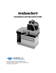
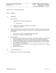
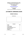
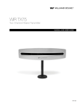
Revolving Door Energy Calculator
Davis Associates, Inc.
43 Holden Road
Newton, MA 02465-1909
U.S.A.
www.davis-inc.com
Copyright © 2011 by Davis Associates, Inc.
Revision B: 2011-11-22
TERMS AND CONDITIONS OF USE
The RDEC (Revolving Door Energy Calculator) program and associated support
materials are subject to TERMS AND CONDITIONS OF USE with which you must
agree and which you must accept before using the RDEC program or associated support
materials.
A copy of the TERMS AND CONDITIONS OF USE is displayed each time the RDEC
program is invoked. A copy is also available on the Davis Associates, Inc., website at:
www.davis-inc.com/ke/terms-condx.html
This is an active hyperlink that will take you directly to the TERMS AND
CONDITIONS OF USE if you are viewing this document on your computer and your
computer has a web browser and access to the internet. Otherwise, manually enter the
above web address into your browser to view the TERMS AND CONDITIONS OF USE.
Revision B: 2011-11-22
- Page 2 of 28 -
CONTENTS
Applicability and Use . . . . . . . . . . . . . . . . . . . . . . . . . . . . . . . . . . . . . . . . . . . . . . 4
Introduction . . . . . . . . . . . . . . . . . . . . . . . . . . . . . . . . . . . . . . . . . . . . . . . . . . . . . 5
Overview . . . . . . . . . . . . . . . . . . . . . . . . . . . . . . . . . . . . . . . . . . . . . . . . . . . . . . . 6
Step-1 S CONFIGURATION . . . . . . . . . . . . . . . . . . . . . . . . . . . . . . . . . . . . . 7
Step-2 S DIMENSIONS and WEIGHTS . . . . . . . . . . . . . . . . . . . . . . . . . . . . . 8
Step-3 S CALCULATE and EVALUATE . . . . . . . . . . . . . . . . . . . . . . . . . . . . 9
Calculate . . . . . . . . . . . . . . . . . . . . . . . . . . . . . . . . . . . . . . . . . . . . . . . . . 9
Evaluate . . . . . . . . . . . . . . . . . . . . . . . . . . . . . . . . . . . . . . . . . . . . . . . . . 10
Parameters by Door Type . . . . . . . . . . . . . . . . . . . . . . . . . . . . . . . . . . . . . . . . . . . 12
Weight vs. mass . . . . . . . . . . . . . . . . . . . . . . . . . . . . . . . . . . . . . . . . . . . . 12
Weight as a function of width . . . . . . . . . . . . . . . . . . . . . . . . . . . . . . . . . 13
Parameters: 3-wing and 4-wing doors with no core . . . . . . . . . . . . . . . . . . . . . 14
Parameters: 3-wing and 4-wing doors with a core . . . . . . . . . . . . . . . . . . . . . . 15
Parameters: 2-wing door with showcases . . . . . . . . . . . . . . . . . . . . . . . . . . . . . 16
Additional Considerations . . . . . . . . . . . . . . . . . . . . . . . . . . . . . . . . . . . . 17
Additional checks . . . . . . . . . . . . . . . . . . . . . . . . . . . . . . . . . . . . . . . 17
Correct specification of diameter . . . . . . . . . . . . . . . . . . . . . . . . . . . . 18
Showcase floor . . . . . . . . . . . . . . . . . . . . . . . . . . . . . . . . . . . . . . . . . 19
Curved panel placement . . . . . . . . . . . . . . . . . . . . . . . . . . . . . . . . . . 20
Parameters all Doors . . . . . . . . . . . . . . . . . . . . . . . . . . . . . . . . . . . . . . . . . . . . . . . 21
Parameters: Ceiling . . . . . . . . . . . . . . . . . . . . . . . . . . . . . . . . . . . . . . . . . . . . 21
Parameters: Point objects . . . . . . . . . . . . . . . . . . . . . . . . . . . . . . . . . . . . . . . 22
Parameters: Extended objects . . . . . . . . . . . . . . . . . . . . . . . . . . . . . . . . . . . . 24
Example 1 . . . . . . . . . . . . . . . . . . . . . . . . . . . . . . . . . . . . . . . . . . . . . . . . 25
Example 2 . . . . . . . . . . . . . . . . . . . . . . . . . . . . . . . . . . . . . . . . . . . . . . . . 26
Epilogue . . . . . . . . . . . . . . . . . . . . . . . . . . . . . . . . . . . . . . . . . . . . . . . . . . . . . . . . 28
Revision B: 2011-11-22
- Page 3 of 28 -
Revolving Door Energy Calculator
Applicability and Use
The kinetic energy equations and results calculated and displayed by the Revolving Door
Energy Calculator (RDEC) program apply when the following conditions are met.
!
The moving components of the revolving door undergo rigid rotation. That is, they
are rigidly ganged together so that they maintain fixed positions and orientations with
respect to each other as the door rotates.
!
The axis of rotation of the door is vertical and is located at the geometric center of
the assembly of moving door components.
!
The thickness of vertically oriented panels is a small fraction of the width of the panel.
!
The distribution of mass within flat vertically oriented panels is uniform in the
horizontal direction across the width of such panels and is immaterial in the vertical
direction.
!
The distribution of mass within curved panels all points of which are at a common,
fixed horizontal distance from the axis of rotation is immaterial in both the horizontal
and vertical directions.
!
The distribution of mass within horizontally oriented surfaces, such as a co-rotating
ceiling and showcase floors, is uniform in the horizontal direction and immaterial in
the vertical direction.
!
The thickness of horizontally oriented surfaces, such as a co-rotating ceiling and
showcase floors, is immaterial.
The kinetic energy equations and results calculated and displayed by the RDEC program
apply equally to all door configurations in which the distances from the axis of rotation of
the centers-of-mass of the door components and the moments-of-inertia of the components
about their own centers-of-mass are identical. Consequently, the angular distribution of
door components about the axis of rotation is immaterial. For example, the flat, radially
directed panels of a 3-wing or 4-wing door need not be uniformly spaced around the axis
of rotation. As a further example, with the identical input parameters, the RDEC kinetic
energy results apply equally to the configuration on the right as to the one on the left.
Revision B: 2011-11-22
- Page 4 of 28 -
Introduction
What is kinetic energy and why does it matter? S Kinetic energy is, as its name implies,
the energy carried by an object as a consequence of its motion. It is important because
the force with which a moving object strikes another is directly proportional to the kinetic
energy carried by the striking object. This means that kinetic energy is the appropriate
measure of the potential of a moving object to cause injury if it strikes a person.
While kinetic energy is directly proportional to the mass of the moving object, it is
proportional to the square of its speed. Thus, if the speed of the object doubles, the force
of its impact will, all else being equal, increase by a factor of four. Because it represents
the potential to cause injury and because it increases rapidly with increasing speed, the
ANSI/BHMA (American National Standards Institute/Builders Hardware Manufacturers
Association) A156.27 national standard for manual and automatic revolving doors
mandates limits on the kinetic energy of a revolving door in various ways in the interest of
user safety. For example, wing sensors are required if an automatic revolving door carries
more than 2.5 lb-ft of kinetic energy, and certain doors are not allowed to carry more
than 7.0 lb-ft of kinetic energy.
It is important to recognize that kinetic energy is a single quantity that is characteristic of
the entire revolving door, much as is its weight. Neither the weight of the door nor its
rotational kinetic energy depends upon location within the door. The entire door has just
a single weight and, at a given rotation speed, the entire door also has just a single kinetic
energy.
The kinetic energy of a revolving door is the sum of the kinetic energies of its component
parts. Each component has a different location and orientation within the door and,
generally, a unique size and shape. Because points closer to the periphery of the door
move faster than points closer to the axis of rotation, the kinetic energy of each
contributing component must be calculated separately and then combined. Consequently,
calculating the kinetic energy of a revolving door is generally much more complicated than
calculating for a sliding, swinging or folding door.
The Revolving Door Energy Calculator (RDEC) program was created to make calculation of
the kinetic energy of a revolving door quick, easy and accurate. All of the required
complicated equations for the various door components are contained within RDEC. The
user has only to enter the basic parameters that describe the door S diameter, rotation
rate, weights or masses of wings, etc. S and RDEC does the rest. Moreover, RDEC
contains a host of additional features to assist in the analysis of design variations, including
the ability to account for components not ordinarily considered, such as a co-rotating
ceiling, showcase floors, control boxes rotating with the door, and novel objects placed
within showcases or elsewhere on the door.
Revision B: 2011-11-22
- Page 5 of 28 -
Overview
There are three basic steps required by the Revolving Door Energy Calculator (RDEC).
1.
CONFIGURATION S Select the type of revolving door from the following
list:
2-wing revolver with showcases.
3-wing revolver with no core.
3-wing revolver with core.
4-wing revolver with no core.
4-wing revolver with core.
2.
DIMENSIONS and WEIGHTS S Specify the parameters that describe each
component of the selected door type.
3.
CALCULATE and EVALUATE S Have RDEC calculate and evaluate the
kinetic energy results for any combination of the specified door components
at any given door rotation rate.
Revision B: 2011-11-22
- Page 6 of 28 -
Step 1 S CONFIGURATION
Choose the door type from the Configuration panel at the upper left of the RDEC display
by selecting the Number of wings, and whether other components are to be included such
as a co-rotating ceiling and showcase floors. Illustrated is the selection of a 2-wing door
with showcases with co-rotating ceiling and showcase floors to be added to the basic door.
Selections are made by clicking on the down arrows, which open drop down lists of the
possible alternatives for each component of the door.
As the specific components of the door configuration are selected, you will notice that
data entry boxes appear within the Dimensions and Weights panels, as required. It is
through these data entries that the specific physical characteristics of the door are
communicated to RDEC.
Comprehensive explanations of all requested parameters appear
in the RDEC Explanation panel when you mouse-over the name of
the parameter, thus making RDEC use self-documenting. This
feature operates throughout.
Revision B: 2011-11-22
- Page 7 of 28 -
Step 2 S DIMENSIONS and WEIGHTS
The widths of the various door panels are entered in the RDEC Dimensions panel, whereas
the weights of the respective panels are entered in the Weights panel.
The up-down arrows to the right of each data entry box are used to select the units
assigned to the respective entry. Although all panel width entries in the illustration above
are in feet, and all weight entries in pounds, you are free to mix units arbitrarily.
Once you enter a value in one of the boxes and hit <Enter> , <Tab-left> or <Tab-right>,
the value enters a list associated with the box that can be viewed by clicking on the down
arrow associated with the box. Values can be recalled from the list by clicking on the
desired value in the drop down list. The value currently appearing in the box can be
deleted from the list by clicking on the trash can to the right of the box.
Revision B: 2011-11-22
- Page 8 of 28 -
Step 3 S CALCULATE and EVALUATE
When the Calculate or the Evaluate button is clicked after entering all required dimensions
and weights for the door configuration, RDEC will first check for and flag any improper or
inconsistent data values and will color the relevant data entry boxes either pink or yellow.
Pink signifies inconsistent values, whereas yellow signifies missing or improper values. You
must make the necessary parameter corrections, if any are required, before the RDEC
Calculate or Evaluate functions will execute.
Calculate S When the Calculate button is clicked, the Results window will display the
kinetic energy results and a summary of the selections and associated values entered by the
user, as illustrated below. The Results apply to the entire door configuration that you
specify, with all components being included.
The kinetic energy of the entire specified door configuration at the current door rotation
rate is displayed at the top of the Results window, followed by the door rotation rates at
which the entire configuration will carry 2.5 lb-ft and 7.0 lb-ft of kinetic energy. The up
and down arrows next to the RPM box directly below the Results window can be used to
select any door rotation rate within the range 0.1 rpm to 10.0 rpm in increments of 0.1
rpm. The kinetic energy of the specified door configuration is re-evaluated and displayed
every time the rotation rate is changed. A scroll bar on the right side of the Results
Revision B: 2011-11-22
- Page 9 of 28 -
Step 3 S Continued
window can be used to view the balance of door configuration parameters if the window is
not large enough to permit viewing of all parameters at once.
If Evaluate was selected prior to selecting Calculate, the door rotation rate in rpm used by
Calculate will be inherited from the value currently being used by Evaluate.
Evaluate S Clicking on the Evaluate button, on the other hand, brings up a window
detailing the kinetic energy of each specified component of the door and the rotation rate
at which that component by itself would carry either 2.5 lb-ft or 7.0 lb-ft of kinetic
energy. The kinetic energies at the specified door rotation rate and the 2.5 and 7.0 lb-ft
rotation rates of the entire combination of components are displayed in the summary at
the bottom of the rightmost three columns. By clicking on the check boxes in the Include
column of the window and next to any Point objects or Extended objects, individual
components can be omitted from or included in the summary in any combination. See the
illustration below.
If Calculate was selected prior to selecting Evaluate, the door rotation rate in rpm used by
Evaluate will be inherited from the value currently being used by Calculate.
Revision B: 2011-11-22
- Page 10 of 28 -
Step 3 S Continued
Like the RDEC Calculate window, the Evaluation window includes an up-down arrow at the
bottom that can be used to select the rotation rate of the door within the range 0.1 rpm to
10.0 rpm in increments of 0.1 rpm. The total and contributing kinetic energy values of all
door components are re-evaluated and displayed every time the rotation rate is changed.
By selecting components using the check boxes in the Include column and next to the
names of any Point objects or Extended objects in the Component column and by varying
the rotation rate, you can explore at will the effect of arbitrary combinations of
components and door rotation rate.
The RDEC Evaluation window also includes at the
lower left a graph of the kinetic energy of the
currently selected combination of door components
as a function of door rotation rate in rpm. The
background of the graph is shaded light green for
kinetic energies in the range 0 to 2.5 lb-ft, light
yellow in the range 2.5 to 7.0 lb-ft, and light red in
the range above 7.0 lb-ft. The graph is recalculated
and displayed each time the combination of components is changed using the check boxes.
The RDEC Evaluation window is closed by clicking on Done at the lower right.
Revision B: 2011-11-22
- Page 11 of 28 -
Parameters by Door Type
The following pages describe, in the order of increasing complexity of input, the
parameters that must be provided for each of the five door types handled by RDEC.
There are two considerations that apply to all door types, which are described here. These
are:
!
The relationship between the weight and mass of a door component, and
!
The ability of RDEC to determine the weight of a door panel based on its width.
Weight vs. mass S The kinetic energy of any moving object depends upon its mass.
However, when using English units, it is customary to use the weight of an object as a
proxy for its mass. Of the possible English units of weight, RDEC uses the pound
exclusively. The standard English unit of mass, which the kinetic energy equations require,
is the slug.
The pound is actually a unit of force and not of mass, but, as the mass of an object is
directly proportional to its weight, it is possible to determine the mass of an object from
its weight if the constant of proportionality is known. By convention, it is assumed that
the weight of all objects is determined at sea level where the acceleration of gravity g is
taken to be 32.17 ft/sec2. Thus, if an object has weight w, its mass in slugs is determined
simply by dividing its weight by g. That is
mass in slugs = w g .
Because weight is such a familiar proxy for mass in the English system, RDEC allows you to
specify the mass of door components by specifying, rather, the weight of the component.
RDEC then automatically divides the weight you specify by g to determine the mass of the
object in slugs.
On the other hand, RDEC also allows you to input the “weights” of door components in
kilograms (kg), though the kilogram is not a unit of weight but a genuine unit of mass in
the Metric system. RDEC understands the distinction and handles the calculation of kinetic
energy appropriately.
This consideration arises also when specifying the moment-of-inertia of an Extended object
in the English system of units. While the English unit of moment-of-inertia is slug-ft2, for
consistency, you are asked, rather, to specify pound-ft2. Just as with weight, in this case
RDEC automatically divides by g to convert pound-ft2 internally to slug-ft2.
Revision B: 2011-11-22
- Page 12 of 28 -
Weight as a function of width S The weights of all moving door components must be
specified by the user in order for their contributions to the kinetic energy of the door to
be determined. You have two options when specifying the weights of door wings and
panels as follows:
!
Enter the weight of the door panel or wing directly, or
!
Allow RDEC to determine the weight of the door panel or wing from its width.
These options apply only to door panels and wings, and not to other components such as
a co-rotating ceiling.
The drop down lists associated with weights to be entered in the Weights panel of RDEC
contain two choices.
!
ANSI Aluminum, and
!
ANSI Clad (generally brass or stainless steel applied to aluminum frames)
You can either enter the weight of the panel or wing directly in the input box, or you can
select ANSI Aluminum or ANSI Clad from the drop down list. If you select from the
drop down list, RDEC will determine the weight of the panel or wing from its width using
the appropriate following formula.
ANSI Aluminum specified:
weight = 2.13 lb/in × (width in inches) + 37.7 lb
ANSI Clad specified:
weight = 2.38 lb/in × (width in inches) + 58.5 lb
These formulae correspond to the panel weights specified in the kinetic energy tables 1A
and 1B in the ANSI/BHMA A156.27-2011 national standard for manual and automatic
revolving doors approved on June 20, 2011.
In most cases, you will have been asked to enter the width of the door panel, which, when
converted internally to inches by RDEC, will be used to determine the weight of the panel
from the above formulae should you select ANSI Aluminum or ANSI Clad.
However, in some circumstances, you will not have been asked for the panel or wing
width. In the case of flat core panels for 3-wing and 4-wing doors, the panel width will
have been inferred by RDEC. In other circumstances you will be required to enter the
panel width to enable RDEC to determine the weight of the panel from one of the
formulae above, though its width may not be required by RDEC for any other purpose.
In these latter circumstances, you do not have to enter the width of the panel if you
specify the weight of the panel directly and do not select either the ANSI Aluminum or
ANSI Clad option.
Revision B: 2011-11-22
- Page 13 of 28 -
Parameters: 3-wing and 4-wing doors with no core
3-wing door with no core.
D
Wing
weight
Ω
4-wing door with no core.
The overall diameter of the door. Units can be feet, inches, meters,
centimeters or millimeters.
Weight of an individual wing in pounds or kilograms. ANSI Aluminum
and ANSI Clad options can also be selected to determine weight.
Rotation rate of door in rpm (revolutions per minute).
Note that, in the cases of 3-wing and 4-wing doors without a core, RDEC takes the width
of a wing to be half the diameter of the door. That is, D/2. Consequently, you do not
have to enter the width of a wing, and wing width is not requested by RDEC.
Co-rotating ceiling, point and extended objects are available optionally from the RDEC
Configuration panel. See beginning on page 21 for a discussion of these options.
Revision B: 2011-11-22
- Page 14 of 28 -
Parameters: 3-wing and 4-wing doors with a core
3-wing door with a core
4-wing door with a core
D
The overall diameter of the door. Units can be feet, inches, meters,
centimeters or millimeters.
r
The width of a radially directed wing. Units can be feet, inches, meters,
centimeters or millimeters.
r panel
weight
The weight of a radially directed wing in pounds or kilograms. ANSI
Aluminum and ANSI Clad options can also be selected to determine
weight.
Core panel The weight of an individual core panel in pounds or kilograms. ANSI
weight
Aluminum and ANSI Clad options can also be selected to determine
weight.
Ω
Rotation rate of door in rpm (revolutions per minute).
Note that, in the case of 3-wing and 4-wing doors with a core, RDEC infers the widths of
the core panels from D, r, and the assumption that the core is either an equilateral triangle
or a square. Consequently, you do not have to enter the width of a core panel, and such
widths are not requested by RDEC.
Co-rotating ceiling, point and extended objects are available optionally from the RDEC
Configuration panel. See beginning on page 21 for a discussion of these options.
Revision B: 2011-11-22
- Page 15 of 28 -
Parameters: 2-wing door with showcases
2-wing door with showcases
Note:
Parameters are specified for one half of the door. RDEC assumes that the other
half of the door is dimensionally identical and takes both halves into account
when calculating rotational kinetic energy.
D
The overall diameter of the door. Units can be feet, inches, meters,
centimeters or millimeters.
r
The width of a radially directed wing. Units can be feet, inches, meters,
centimeters or millimeters.
d1
Width of the first flat showcase panel. Note that it is immaterial which of
the two flat showcase panels is considered first and which is considered
second. Units can be feet, inches, meters, centimeters or millimeters.
d2
Width of the second flat showcase panel. Note that it is immaterial which
of the two flat showcase panels is considered first and which is considered
second. Units can be feet, inches, meters, centimeters or millimeters.
Curved
Panel
width
Unless you want RDEC to compute the weight of each curved panel from
the width of the panel and the formulae for the standard ANSI
Aluminum or ANSI Clad materials, you do not have to enter the width of
a curved panel in the RDEC Dimensions panel. Otherwise, when required,
the units can be feet, inches, meters, centimeters or millimeters.
r panel
weight
The weight of a radially directed wing in pounds or kilograms. ANSI
Aluminum and ANSI Clad options can also be selected to determine
weight.
Revision B: 2011-11-22
- Page 16 of 28 -
Parameters: 2-wing door with showcases (continued)
d1 weight
The weight of the first flat showcase panel in pounds or kilograms. ANSI
Aluminum and ANSI Clad options can also be selected to determine
weight. Note that it is immaterial which of the two flat showcase panels is
considered first and which is considered second.
d2 weight
The weight of the second flat showcase panel in pounds or kilograms.
ANSI Aluminum and ANSI Clad options can also be selected to
determine weight. Note that it is immaterial which of the two flat
showcase panels is considered first and which is considered second.
Curved
panel
weight
The weight of an individual curved panel in pounds or kilograms. ANSI
Aluminum or ANSI Clad options can also be selected to determine
weight.
Showcase
floor
weight
The total weight of an individual showcase floor in pounds or kilograms.
ANSI Aluminum and Clad options not available. Note that this
parameter is required only if you have selected the Showcase floor option
in the RDEC Configuration panel.
Ω
Rotation rate of door in rpm (revolutions per minute).
Co-rotating ceiling, point and extended objects are available optionally from the RDEC
Configuration panel. See beginning on page 21 for a discussion of these options.
Additional Considerations
Additional checks S Because the geometry of a 2-wing revolving door with showcases is
considerably more complicated than that of the other types of doors, RDEC performs
checks on the consistency of parameters you enter that have no analog with the other
door types. In addition to the more obvious checks, such as that a wing width cannot be
specified as being negative, RDEC performs the following checks on 2-wing revolving doors
with showcases.
!
That the width of each flat showcase panel, when added to the width of the
radially directed panel is sufficient to reach the closer curved panel located at the
distance D/2 from the axis of rotation.
!
That the width of each flat showcase panel is not so wide that, when folded
completely back against the radially directed panel to which it is attached, it
reaches, or extends beyond, the further curved panel also at the distance D/2
from the axis of rotation.
Revision B: 2011-11-22
- Page 17 of 28 -
Parameters: 2-wing door with showcases (continued)
!
That the flat showcase panels from one showcase do not intersect the flat panels of
the other showcase.
Correct specification of diameter S It is important that the diameter D correspond to the
distance, measured through the axis of rotation, between the curved showcase panels and
not, for example, the inside diameter of the cylinder within which the door rotates.
Otherwise, the RDEC calculations of kinetic energy may be invalid for the reasons
explained below.
RDEC uses the width of the radial panel r, the widths of the flat showcase panels d1 and d2,
and the overall diameter of the door D to determine the vertex angle of the showcase.
That is, the angle between the two flat showcase panels where they join the end of the
radial panel. This in turn determines the distance along the curved showcase panel
between the points at which the two flat showcase panels meet the curved showcase panel.
How this is done is illustrated in the Figures below.
Flat showcase panels with correctly
specified door diameter D.
Flat showcase panels with incorrectly
specified door diameter D.
The Figure at the left illustrates that the flat showcase panels, which “pivot” around the
end of the radially directed wing at the point labeled “Vertex,” intersect the curved
showcase panel at the points where the arcs of radius d1 and d2 about the vertex intersect
the curved showcase panel. The radius of the curved showcase panel is taken to be half
the overall door diameter. That is, D/2.
The Figure at the right illustrates the effect of specifying a door diameter D that is larger
than it should be. For example, if D were set to the inside diameter of the cylinder within
Revision B: 2011-11-22
- Page 18 of 28 -
Parameters: 2-wing door with showcases (continued)
which the door rotates, the tips of the flat showcase panels would rotate further along the
dashed arcs of radii d1 and d2 than they should until they meet the incorrectly specified
curved panel, whose radius about the axis of rotation is too large. As a consequence, the
angle between the flat showcase panels at the vertex is smaller than it should be. This
causes the centers-of-mass of the flat showcase panels to move further from the axis of
rotation than they should be. And, the curved showcase panel is also further from the
axis of rotation than it should be. Both errors act to increase the calculated kinetic energy
of the door above the correct value corresponding to the Figure at the left.
Moreover, the error also results in the showcase floor, which is the roughly triangular area
bounded by the two flat showcase panels and the curved panel, having the incorrect shape
and location. This will introduce yet additional errors in the kinetic energy calculation if
you have elected to include the effect of the showcase floors.
Showcase floor S RDEC understands that the shape and location of the showcase floor are
determined by the limits set by the two flat showcase panels and the curved panel to which
the flat showcase panels are attached. The showcase floors are illustrated by the grey areas
shown in the two Figures below.
Showcase floor vertex angle less
than 180 degrees.
Showcase floor vertex angle
greater than 180 degrees.
The Figure on the left illustrates the usual situation in which the angle at the vertex of the
showcase is less than 180 degrees, while the Figure on the right illustrates the situation in
which the vertex angle is greater than 180 degrees. While it is currently unlikely that you
will encounter a showcase with a vertex angle greater than 180 degrees, as on the right, the
Revision B: 2011-11-22
- Page 19 of 28 -
Parameters: 2-wing door with showcases (continued)
kinetic energy equations used by RDEC are nevertheless set up to accommodate both
situations.
The equations employed by RDEC to calculate the contribution to the kinetic energy of
the door by the showcase floors are exact for the shapes illustrated. That is, they take full
and proper account of the fact that two sides of the showcase floors are straight, while the
third is bounded by an arc of radius equal to half the overall diameter of the door.
Moreover, they handle equally well any vertex angle, whether less than, equal to or
greater than 180 degrees.
Curved panel placement S The rotational kinetic energy of an element of mass revolving
around a specified axis at a fixed radial distance from the axis is entirely independent of
the angular position of the mass element about the axis. This applies as well to collections
of mass elements. Since all of the mass elements comprising the curved showcase panels
are at the same radial distance from the axis of rotation and since they all rotate with the
same speed, the location of attachment of the curved panel to the two flat showcase panels
is immaterial and has no bearing on the kinetic energy results calculated by RDEC.
In the illustrations of 2-wing revolving doors provided here for purposes of labeling and
defining input parameters, the curved panels are shown attached to the showcases in such a
way that the extent of the curved panel extending ahead of the showcase in the direction
of rotation is less than the extent extending aft of the showcase. However, the amount by
which the curved panels extend fore and aft of the showcases is immaterial because the
radial distance of all mass elements within the curved panels is fixed and remains unaltered
for all combinations of fore and aft extent. This applies as well to the situation in which
the fore and aft extents of the curved showcase panel attached to one showcase are not
identical to those of the curved panel attached to the other showcase. The kinetic energy
equations employed by RDEC for 2-wing revolving doors with curved showcase panels
apply equally to all combinations of fore and aft extent.
Thus, you need not be concerned if the placement of the curved showcase panels of the
door for which you want kinetic energy results from RDEC does not match the
illustrations with respect to fore and aft extent. The kinetic energy equations and results
reported by RDEC apply equally to all such variations of placement.
Revision B: 2011-11-22
- Page 20 of 28 -
Parameters all Doors
Parameters: Ceiling
When you select a co-rotating ceiling for inclusion in the kinetic energy calculations, the
Ceiling diameter parameter box opens in the RDEC Dimensions panel and the Ceiling
weight parameter box opens in the RDEC Weights panel.
Ceiling
diameter
The diameter of the co-rotating ceiling. Not required to be equal to the
overall door diameter D. Units can be feet, inches, meters, centimeters or
millimeters.
Ceiling
weight
The weight of the co-rotating ceiling in pounds or kilograms. ANSI
Aluminum and Clad options not available.
Note that the weight of the ceiling is assumed to be distributed uniformly over the circular
area of the ceiling. If non-uniformly distributed masses rotate with the ceiling, such as
structural beams or a control box, these should be accounted for using the Point objects
and Extended objects options, as appropriate. The weight specified here for the ceiling
should be restricted to that portion of the weight of the ceiling that is uniformly
distributed over the entire ceiling area and should not include the weights of the nonuniformly distributed masses. The latter are properly accounted for using the Point
objects and Extended objects options.
Revision B: 2011-11-22
- Page 21 of 28 -
Parameters: Point objects
When you select a point object for inclusion in the
kinetic energy calculations, the Name point objects
parameter box opens in the RDEC Dimensions panel into
which you should enter the name (maximum of 20
characters) by which you want the point object to be
designated. On hitting <Enter>, <Tab-left> or <Tabright>, a new box labeled “Add a point object:” will
open within which you can enter the following
parameters characterizing the point object. A maximum
of eight point objects can be defined.
Name
The name by which you want the point object to be designated. This will
already be filled in for you, but you may change the filled in name.
Weight
The weight of the point object in pounds or kilograms.
Distance
from axis
of
rotation
The radial distance at which the named point object is located from the
axis of rotation of the door. Units can be feet, inches, meters, centimeters
or millimeters. Must not exceed the larger of the door radius or, if
specified, the ceiling radius.
On every
wing
Check this box if a duplicate of the named point object is to be associated
with every wing of the door. Otherwise, if only one instance of the point
object is to be included, leave this box unchecked.
Once you have hit Add in the “Add a point object:” box, the name of the point object
will be added to the drop down list associated with the Name point objects box in the
RDEC Dimensions panel. The list can be viewed by clicking on the down arrow associated
with the Name point objects box. Names can be recalled from the list by clicking on the
desired name in the drop down list. The name currently appearing in the box can be
deleted from the list by clicking on the trash can to the right of the box.
To add a new point object, highlight and delete with the <Delete> key, or otherwise
change, the name that currently appears in the Name point objects box. This does not
result in the deletion of the currently named object but, rather, merely clears space for
you to enter the name of the next point object you want to define. Enter the name of the
new object and hit <Enter>, <Tab-left> or <Tab-right> and proceed as described above.
If the name of the new point object you have entered is identical to one already defined
and, consequently, is already on the Name point objects drop down list, the “Add a point
object:” box will not open to allow you to enter parameter values for the object. If this
occurs, you can either change the name you have entered to another not already defined,
Revision B: 2011-11-22
- Page 22 of 28 -
or you can edit the parameter values associated with the object you have named by
selecting “Point object...” from the drop down list associated with EDIT at the top left of
the RDEC window.
If any of the parameters you have entered in the “Add a point object:” window are
flagged subsequently by RDEC as being in error, you can likewise edit your entries by
selecting “Point object...” from the drop down list associated with EDIT at the top left of
the RDEC window. The point object whose parameters will be opened for editing is the
one whose name is currently displayed in the Name point objects entry box in the RDEC
Dimensions panel.
A point object is characterized by a mass distribution whose self moment-of-inertia is
negligible. Consequently, only the mass of the object and its distance from the axis of
rotation materially affect the overall kinetic energy of the door. If the self moment-ofinertia is not negligible, you should use instead the Extended objects option in the RDEC
Configuration panel to characterize the object.
Revision B: 2011-11-22
- Page 23 of 28 -
Parameters: Extended objects
When you select an extended object for inclusion in the
kinetic energy calculations, the Name ext’d objects
parameter box opens in the RDEC Dimensions panel into
which you should enter the name (maximum of 20
characters) by which you want the extended object to be
designated. On hitting <Enter>, <Tab-right> or <Tableft>, a new box labeled “Add an extended object:” will
open within which you can enter the following
parameters characterizing the extended object. A
maximum of eight extended objects can be defined.
Name
The name by which you want the extended object to be designated. This
will already be filled in for you, but you may change the filled in name.
Weight
The weight of the extended object in pounds or kilograms.
Distance
from axis
of
rotation
The radial distance at which the center-of-mass of the named extended
object is located from the axis of rotation of the door. Units can be feet,
inches, meters, centimeters or millimeters. Must not exceed the larger of
the door radius or, if specified, the ceiling radius.
Momentof-inertia
The moment-of-inertia of the named extended object about its own
center-of-mass. That is, its self moment-of-inertia. Units can be lb-ft2 or
kg-m2.
On every
wing
Check this box if a duplicate of the named extended object is to be
associated with every wing of the door. Otherwise, if only one instance
of the extended object is to be included, leave this box unchecked.
Once you have hit Add in the “Add an extended object:” box, the name of the extended
object will be added to the drop down list associated with the Name ext’d objects box in
the RDEC Dimensions panel. The list can be viewed by clicking on the down arrow
associated with the Name ext’d objects box. Names can be recalled from the list by
clicking on the desired name in the drop down list. The name currently appearing in the
box can be deleted from the list by clicking on the trash can to the right of the box.
To add a new extended object, highlight and delete with the <Delete> key, or otherwise
change, the name that currently appears in the Name ext’d objects box. This does not
result in the deletion of the currently named object but, rather, merely clears space for
you to enter the name of the next extended object you want to define. Enter the name of
the new object and hit <Enter>, <Tab-left> or <Tab-right> and proceed as described
above.
Revision B: 2011-11-22
- Page 24 of 28 -
Parameters: Extended objects (continued)
If the name of the new extended object you have entered is identical to one already
defined and, consequently, is already on the Name ext’d objects drop down list, the “Add
an extended object:” box will not open to allow you to enter parameter values for the
object. If this occurs, you can either change the name you have entered to another not
already defined, or you can edit the parameter values associated with the object you have
named by selecting “Extended object...” from the drop down list associated with EDIT at
the top left of the RDEC window.
If any of the parameters you have entered in the “Add an extended object:” window are
flagged subsequently by RDEC as being in error, you can likewise edit your entries by
selecting “Extended object...” from the drop down list associated with EDIT at the top left
of the RDEC window. The extended object whose parameters will be opened for editing is
the one whose name is currently displayed in the Name ext’d objects entry box in the
RDEC Dimensions panel.
An extended object is characterized by a mass distribution whose self moment-of-inertia is
not negligible and must, therefore, be included in the calculation of the total kinetic
energy of the door. If the self moment-of-inertia is in fact negligible, it is preferable that
you use instead the Point objects option in the RDEC Configuration panel to characterize
the object.
Example 1 S As an example of the use of the Extended objects option with English units,
consider that a 6 foot long horizontal beam weighing 25 pounds is attached to the ceiling
and revolves with the door. On the assumption that the mass of the beam is uniform
along its length, the center-of-mass of the beam is located at its center. For the purposes
of RDEC, the moment-of-inertia of a uniform beam about its own center-of-mass is
I=
1
W L2
12
where W is the weight of the beam in pounds, L is the length of the beam, and I is its
moment-of-inertia about its center-of-mass.
Note that the above is just the well known equation for the moment-of-inertia about its
own center-of-mass of a uniform beam of mass M, but with W substituted for the mass M.
For purposes of the RDEC program when using English units, W (pounds) should always
be substituted, as above, for the mass (slugs) in any moment-of-inertia expression that you
use or derive. However, when using metric units, the true mass (kilograms), rather than
the weight, of the object should be used.
Continuing with the example, the moment-of-inertia of the subject beam about its own
center-of-mass is, using the above expression,
Revision B: 2011-11-22
- Page 25 of 28 -
Parameters: Extended objects (continued)
moment-of-inertia =
25 (6) 2
= 75 lb-ft2.
12
On the assumption that the center-of-mass of the beam is located 3.2 feet from the axis of
rotation of the door, the moment-of-inertia of 75 lb-ft2 along with the weight of 25 pounds
and the distance to the center-of-mass of 3.2 feet are entered into the appropriate boxes in
the “Add an extended object:” box, as illustrated at the top of page 24.
Example 2 S As a second example of the use of the Extended objects option, consider a
3-wing revolving door with a core that includes a core floor and that the contribution to
the overall kinetic energy of the door from the core floor is to be included in the RDEC
calculations. Since the moment-of-inertia of the core floor about its own center-of-mass is
not negligible, it is handled appropriately via the Extended objects option.
To use the Extended objects option for this purpose, it is necessary for you to determine
and enter three parameters S the radial distance of the center-of-mass of the floor from
the axis of rotation, the weight of the floor and the moment-of-inertia of the floor about
its own center-of-mass.
Since the cross section of the door core, and hence the shape of the floor, is a regular
polygon and since the geometric center of the polygon, which is also its center-of-mass,
coincides with the axis of rotation of the door, the radial distance of the center-of-mass
from the axis of rotation is zero. Therefore, zero should be entered for the Distance from
axis of rotation parameter.
The weight of the core floor in pounds should be entered for the Weight parameter.1
Finally, the moment-of-inertia about its own center-of-mass of a 3-sided regular polygonal
(equilateral triangle) floor is 2
1
I 3 = Wd 2
4
1
If the radial distance to the center-of-mass of an extended object is in fact zero, as
here, the rotational (point or center-of-mass) kinetic energy of the object is unaffected by
the Weight parameter and depends, rather, only on the self moment-of-inertia and the
rotation rate of the door.
2
For a derivation of this equation, as well as for a 4-sided and n-sided core floors, see
Appendix 4 of Derivation of the Kinetic Energy Equations used by the Revolving Door Energy Calculator
(RDEC) Program available on the Davis Associates, Inc., website.
Revision B: 2011-11-22
- Page 26 of 28 -
Parameters: Extended objects (continued)
where, if using English units, W is the weight of the floor in pounds, d is the distance from
the geometric center of the floor (axis of rotation) to any vertex of the polygonal floor in
feet, and I3 is the moment-of-inertia in units of pound-feet.2 See also the highlighted text
on page 25.
As can be easily concluded from the Figures at the top of page 15, the distance from the
geometric center of the core floor to a vertex is
d=
D
−r
2
so that the moment-of-inertia is
2
W⎛D ⎞
I 3 = ⎜ − r⎟ .
⎠
4⎝2
If the weight W of the core floor is 65 pounds, the overall door diameter D is 12 feet and
the width r of a radial panel is 3.5 feet, then the moment-of-inertia of the core floor is
I 3 = 1016
. lb−ft 2
and this value should be entered for the Moment-of-inertia parameter.
Revision B: 2011-11-22
- Page 27 of 28 -
Epilogue
If you have questions about the Revolving Door Energy Calculator that are not covered by
this manual, the FAQ (Frequently Asked Questions) file on the Davis Associates, Inc.,
website may be of help. Please go to:
www.davis-inc.com/ke/faq
You can also report problems or submit comments, questions or suggestions at the above
address.
If you need an additional copy of the RDEC manual, or want to check that you have the
latest version of the manual, please go to:
www.davis-inc.com/ke/help/manual
?G H@
Davis Associates, Inc. • 43 Holden Road • Newton, MA U.S.A. 02465-1909
617-244-1450
Revision B: 2011-11-22
- Page 28 of 28 -