1
Connectors
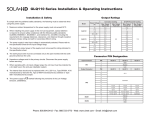
Table 2: Ac Input
Table 3: PFC Input Connector (Control & Signals)
Pin #
1
2
3
function
N
1
~
2
barrier type
Sh30: three #6-32 b.h. screws
6 in.-lb. (0.67 n-m) max. torque
SH45: three M4 screws
7 in.-lb. (0.79 n-m) max. torque
3
Ac neutral
Dc -
Ac line (hot)
Dc +
1
6
Pin #
5
10
Mates with:
molex 90142-0010 housing
Molex 90119-2110 terminal
Connector kit available, part
number 70-841-004
+ Remote sense (single or dual o/p main)
2
Remote margin/V. program (single o/p)
3
Margin high (single o/p)
- Remote sense/margin low (single or
dual o/p main)
5
Spare
6
Module isolated inhibit (single or dual o/p)
7
Module inhibit return (single or dual o/p)
8
Current share (SWP) (single or dual o/p main)
9
+ Remote sense V2 (dual o/p, single is spare)
10
- Remote sense V2 (dual o/p, single is spare)
function
1
Input ac OK (emitter)
2
Input ac OK (collector)
3
Global dc OK (emitter)
4
Global dc OK (collector)
5
No connection
6
Global inhibit/optional enable logic “0”
7
Global inhibit/optional enable logic “1”
8
Global inhibit/optional enable return
9
+5 VSB housekeeping (1 A max.)
10
+5 VSB housekeeping return
Table 5: I2C Bus Output Connector
function
1
4
Mates with:
molex 90142-0010 housing
Molex 90119-2110 terminal
Connector kit available, part
number 70-841-004
5
10
1
6
Chassis (earth) ground
Table 4: Dc Output Module Connector (Control & Signals)
Connector J1
Pin #
Connector J1
Pin #
Connector J2
10
5
6
1
Mates with:
JST phdr-10vs housing
jst sphd-002t-p0.5 terminal
(for 24–28 AWG wire)
jst sphd-001t-p0.5 terminal
(for 24–28 AWG wire) or
landwin 2050s1000 housing
landwin 2053t011P terminal
Connector kit available, part
number 70-841-023
function
1
2
No connection
3
4
Serial clock signal (SCL)
5
Serial data signal (SDA)
6
Address bit 0 (A0)
7
Address bit 1 (A1)
8
Address bit 2 (A2)
9
Secondary return (GND)
10
5 VCC external bus (1 A max.)
notes:
• M4 x 8mm screws for all single output modules; maximum torque is 10 in.-lb. (1.13 N-m). M3 x 8mm screws for dual output
module; maximum torque is 5 in.-lb. (0.57 N-m).
• 36 W triple output module mates with Molex 09-91-0600 housing and Molex 26-60-5060 terminal.
• Single and dual output modules have a green DC OK LED.
Installation/Safety Requirements
WARNING—Risk of Electrical Shock
No user-serviceable parts. Do not open the power supply. Do not replace components.
!
• The earth ground wire must be connected only to the point marked with the earth ground symbol (on the unit). If the earth ground
wire is connected by a screw, the wire must have a ring terminal secured by a lock washer to prevent accidental loosening.
• A safety approved (e.g. UL, CSA, CE) power cord and plug, with an appropriate wire gauge for the rated input current, must be
provided by the end system manufacturer. Additional ferrites may be required on the power cord for radiated emissions testing and
are system dependent.
• The power supply must be installed in a properly grounded and shielded metal enclosure.
• An accessible disconnect device shall be installed external to the equipment.
• The power supply is CE marked following the provisions of the Low Voltage Directive 2006/95/EC only.
• Please refer to our Web site for additional information on the optional CANBUS/RS485 interface.
Phone: 800.894.0412 - Fax: 888.723.4773 - Web: www.clrwtr.com - Email: [email protected]