1
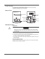
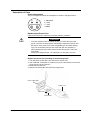
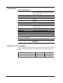
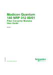
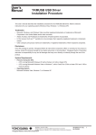
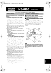
User’s
Manual
Yokogawa Electric Corporation
701934
Power Supply
IM 701934-01E
2nd Edition
Foreword
Thank you for purchasing the 701934 Power Supply.
This user's manual contains useful information about the functions and
operating procedures of the 701934 Power Supply as well as precautions that
should be observed during use. To ensure proper use of the instrument, please
read this manual thoroughly before beginning operation.
After reading this manual, please keep it in a convenient location for reference
whenever a question arises during operation.
Revisions
1st Edition: May 2004
2nd Edition: November 2005
2nd Edition: November 2005 (YK)
All Rights Reserved, Copyright © 2004 Yokogawa Electric Corporation
IM 701934-01E
1
The following markings are used in this manual.
Improper handling or use can lead to injury to the user or damage
to the instrument. This symbol appears on the instrument to
indicate that the user must refer to the user’s manual for special
instructions. The same symbol appears in the corresponding place
in the user’s manual to identify those instructions. In the manual,
the symbol is used in conjunction with the word “WARNING” or
“CAUTION.”
WARNING
Describes precautions that should be observed to prevent the
danger of injury or death to the user.
CAUTION
Describes precautions that should be observed to prevent minor or
moderate injury, or damage to the instrument.
Note
Provides important information for the proper operation of the
instrument.
Checking the Contents of the Package
If some items are missing or otherwise inconsistent with the contents
description, please contact your dealer or nearest YOKOGAWA representative.
701934 Power Supply (main unit)
Accessories
· User's manual (this document)
1
· Power cord
1
· Spare fuse (inside the fuse holder) 1
T3.15AL/250 V, 5 mm (dia.) x 20 mm
2
IM 701934-01E
Contents
Foreword ........................................................................................................................... 1
Revisions .......................................................................................................................... 1
The following markings are used in this manual. .............................................................. 2
Checking the Contents of the Package ............................................................................ 2
Symbols Used on This Instrument .................................................................................... 4
The instrument is marked with the following symbols. ...................................................... 4
Important Information for Users ........................................................................................ 5
Product Overview ............................................................................................................. 6
Names of Parts ................................................................................................................. 6
Operating Procedure ........................................................................................................ 6
Preparation ............................................................................................................ 6
Performing Measurement ...................................................................................... 6
Description of Parts .......................................................................................................... 7
Power Receptacles ............................................................................................... 7
Replacing the Power Fuse .................................................................................... 7
Specifications .................................................................................................................... 8
Product Specifications ........................................................................................... 8
Standards Compliance .......................................................................................... 8
Malfunction? First, Investigate. ......................................................................................... 8
IM 701934-01E
3
Symbols Used on This Instrument
This is an IEC safety class I instrument (with protective grounding).
The following general safety precautions must be taken during all phases of
operation, service, and repair of this instrument. If this instrument is used in a
manner not specified in this manual, the protective features provided by the
instrument may be impaired. Also, Yokogawa Electric Corporation assumes no
liability for the customer's failure to comply with these requirements.
The instrument is marked with the following symbols.
To avoid injury, death of personnel or damage to the instrument, the
operator must refer to an explanation in the User's Manual or Service
Manual.
Functional grounding terminal (This terminal should not be used as a
“Protective grounding terminal”.)
Alternating current.
ON (power).
OFF (power).
4
IM 701934-01E
Important Information for Users
Please heed the following warnings and cautions to ensure safe use of the
instrument and to obtain maximum performance.
WARNING
This instrument connects to a grounding wire using the included
grounding type 2-prong power cord. To prevent accidents such as
electric shock, connect the power cord to a grounded 2-prong outlet.
CAUTION
• Do not expose the instrument to vibration or physical shock during
shipping and handling. Take particular caution never to drop the
instrument.
• Avoid storing or using the instrument in locations that are exposed to
direct sunlight, high temperatures, or condensation. These conditions
can result in deformation, discoloring, or other changes causing failure
to meet product specifications.
• Before using the instrument, please perform an inspection and
operational test to check for any damage that may have occurred due to
improper storage or shipping. If damage is found, contact your nearest
dealer or Yokogawa representative.
• When unplugging the power cord from the outlet or the instrument,
never pull by the cord itself. Always hold and pull by the plug.
• This instrument is not waterproof or dustproof. Do not use the
instrument in locations with a large amount of water or dust.
• To clean the instrument, wipe using a soft cloth with a small amount of
water or mild detergent. Never use detergents that contain benzene,
alcohol, acetone, ethyl compounds, ketones, thinner, or gasoline as
deformation or discoloration can result.
IM 701934-01E
5
Product Overview
This instrument is a power supply for probes.
Four power supply receptacles are located on the front panel, allowing
simultaneous powering of up to four probes.
Names of Parts
Power indicator
POWER
GND
Power switch
OUTPUT
PROBE 1
PROBE 2
PROBE 3
PROBE 4
Power ON
Power OFF
Power receptacles
Grounding
terminal
100-240V AC~
170VA MAX 50/60Hz
POWER
ON
Power cord
inlet
Fuse holder
OFF
FUSE 250V T 3.15AL
Rear view
Front view
Operating Procedure
Preparation
CAUTION
Before turning on the power, make sure that the power supply voltage
indicated on the back of the instrument matches that of the power outlet
you are using.
1 Turn the power switch OFF, then connect the power cord.
2 Connect the power plug of the DL series wide bandwidth current probe you
are using to a power receptacle on the instrument.
3 Turn ON the power switch, and confirm that the power indicator on the front
panel illuminates.
Performing Measurement
Refer to the user's manual of the current probe you are using (model 700937,
701930, 701931, 701932 or 701933).
6
IM 701934-01E
Description of Parts
Power Receptacles
The pin arrangement within the receptacles is shown in the figure below.
2
3
1
4
1
2
3
4
Not used
+12V
–12V
GND
Replacing the Power Fuse
If the power fuse blows, follow the procedure below to replace it.
WARNING
• To avoid accidents such as electric shock, you must disconnect the
power cord from the outlet before attempting to replace the power fuse.
• Be sure to use a power fuse of the designated type and rating. Bodily
injury can result when using a fuse other than the one specified, or
when shorting the fuse holder. Never use the wrong fuse or short the
fuse holder.
Power fuse rating and type: T3.15AL/250 V, 5 mm (dia.) x 20 mm
Replace the power fuse according to the following steps.
1 Turn the power switch OFF, then remove the power cord.
2 Use a flathead screwdriver or similar tool to pry the fuse holder out from the
power supply inlet and remove.
3 Replace the power fuse.
4 Reinsert the fuse holder into the power supply inlet.
Power supply inlet
Power cord
Spare fuse
Fuse holder
IM 701934-01E
7
Specifications
Product Specifications
Compatible Probes
700937 Current Probe, 700939 FET Probe
701920 Differential Probe, 701930 Current Probe
701931 Current Probe, 701932 Current Probe
701933 Current Probe
No. of Power Receptacles
4
Output Voltage
±(12 ± 0.5) V
Operating Temperature/Humidity 0 to 40°C, 80% RH or less (no condensation may be
present)
Storage Temperature/Humidity -10 to 50°C, 80% RH or less (no condensation may
be present)
Operating Altitude
Up to 2000 m, indoors
Rated Output Current
±2.5 A (total value for each output)
Rated Supply Voltage
100 to 240 VAC
(actual power supply voltage may fluctuate within
±10% of the rating)
Ripple Voltage
50 mVp-p
Rated Power Supply Frequency 50/60 Hz
Rated Power
170 VA (at the rated output current)
External Dimensions
80 (W) × 119 (H) × 200 (D) mm
Weight
Approx. 1.2 kg
Accessories
Power cord, user's manual, spare fuse
Standards Compliance
Safety
EMC
EN61010-1, pollution degree 2
EN61326
EN61000-3-2
EN61000-3-3
Malfunction? First, Investigate.
Contact your nearest Yokogawa dealer or representative if servicing is required,
or if the instrument fails to operate normally after taking appropriate corrective
actions.
8
Description
Possible Problem
Corrective Action
No power coming to the instrument.
Power fuse blown.
Replace the fuse.
IM 701934-01E