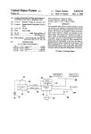
1
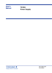
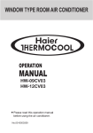
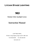
USER'S MANUAL
TITAN SERIES
ASH-28AT
Remote control operation procedure
Please read this
OWNERS MANUAL
carefully prior to
use
Structure and mechanism
CONTENTS
Care and maintenance
Functions and Working temperature range
1
Operation mechanism
2
Technical specifications
4
Important notices
5
Structure description
6
Name and Function-Remote control
7
Name and Function-Remote control(Remove the cover)
8
COOL mode operation procedure
9
HEAT mode operation procedure
10
DRY mode operation procedure
11
SLEEP mode operation procedure
12
AUTO mode operation procedure
13
TIMER mode operation procedure
14
How to insert batteries
15
Emergency run operation procedure
16
Air flow direction adjustment procedure
16
Special performance
17
Operation conditions
17
Installation precaution
18
Care and maintenance
19
When malfunction happening
20
Installation dimension diagram
21
Installation location
22
Install the indoor unit
23
Install the outdoor unit
25
Routine check after installation
27
For to prevent flicker impressions during the start of the compressor (technical process)following installation
conditions do apply.
1 ASH-28AT will be connected only to a supply with the relevant system impedance no
more than Zmax=0.267 Ω
2 The power connection for the air conditioner has to be done at the main power distribution. This distribution has to
be of an low impedance. Normally the required impedance is eached at a 32A fusing point.
3 No other equipment has to be connected to this power line.
4 For detailed installation acceptance please refer to your contract with the power supplier, if restrictions do apply
far products like washing machines air conditioners or electrical ovens.
5 For power details of the air conditioner refer to the rating plate of the product.
6 For any question contact your local seller.
7 This product must not be disposed together with the domestic waste.
This product has to be disposed at an authorized place for recycling
of electrical and electronic appliances.
8 The fuse indoor: T5AL, AC250V, outdoor: T3.15AL, AC250V.
Functions
Cooling in summer
Dehumidifying in rainy or humid season
In hot summer,air conditioner can cool room air by
transfering heat out.
Without reducing room temp.,air conditioner can
dehumidify and make room air dry and comfortable.
Operating automatically
Heating in winter (heat pump type)
According to room temp. change,microcomputer can
In cold winter,air conditioner can supply warm air to
automaticlly set COOL or HEAT or FAN operation mode,
rise room temp.
so as for best effect.
AUTO
Working temperature range
Indoor side DB/WB(
Maximum cooling
32/23
Minimum cooling
21/15
Maximum heating
27/
)
Outdoor side DB/WB( )
43/26
24/18
Minimum heating
5/
6
Working voltage:50Hz 230V
Installation precaution:
To prevent possible hazards due to insulation failure,the unit must be grounded.
Provide a power outlet to be used exclusively for each unit,and a power supply disconnect and circuit breaker and
current fuse protector should be provide in the exclusive line.
Each wiring connection must be done in accordance with the wiring system diagram.Wrong wiring may cause the unit
to misoperate or become damage.
Please cut off power supply when unit will not be used for a long time.
⑤ An all-pole disconnection switch having a contact separation of at least 3mm in all poles should be connected in fixed wiring.
1
Operation mechanism
Cooling cycle
Connected with pipes,indoor unit and outdoor unit form a refrigeration system.With power,compressor takes in
low temp.and low pressure refrigerant vapour from evaporator of indoor unit,presses it into high temp.and high
pressure gas,then discharges it into condenser of outdoor unit.By help of axialflow fan,heat is removed to outdoor
air from the gas which then condenses into liquid.After capillary tube throtting,the liquid drops temp.and pressure,
flows into evaporator.There,by help of cross-flow fan,the liquid absorbs heat from room air,evaporates and
becomes low pressure vapour which then flows into compressor again,beginning next cooling cycle.Therefore,
heat is transfered from indoor to outdoor,and room gets cool.
Ventilation cycle
Ventilation cycle divides into indoor and outdoor two parts.With suction of cross-flow fan,room air flows through
filters,exchanges heat in evaporator,then returns to room.In this way,room air can be cool and dehumidified.At
the same time,pumped by axial-flow fan,outdoor air flows through condenser and exchanges heat.
Heating cycle
Heat pump type air conditioner uses a commutator (4-way electromagnetic valve) to change refrigerant flow
direction.When heating,refrigerant firstly enters indoor heat-exchanger,releasing heat and condensing.Then it
enters outdoor heat-exchanger,absorbing heat and evaporating.Because consumption power changes into heat
which is discharged in room,heating efficiency is very good.
2
(1) Schematic diagram of cool only type
1.Compressor
2.Outdoor heat-exchanger
3.Filter
4.Capillary tube
5.Stop valve
6.Connecting pipes
7.Indoor heat-exchanger
8.Accumulator
(2) Schematic diagram of heat pump type
1.Compressor
2. 4-way electromagnetic valve
5.Master capillary tube
9.Connecting pipes
6.Check valve
7.Auxiliary capillary tube
10.Indoor heat-exchanger
3
3.Outdoor heat-exchanger
11.Accumulator
4.Filter
8.Stop valve
Technical specification
Model
ASH-28AT
Funcitions
Cool/Heat
Cooling capacity(W)
8000
Heating capacity(W)
8800
Power supply
Rated input
Input power
230V~50Hz
Cooling(W)
4000
Heating(W)
3600
Cooling(W)
2800
Heating(W)
2800
R410A 2600g
Refrigerant
Noise dB(A)
Indoor
49
Outdoor
60
Climate type
T1
Moisture protection
IP24
Isolation
Dimension
(mm)
Weight(kg)
I
Indoor unit
1178*326*227
Outdoor unit
1006*340*847
Indoor unit
17.5
Outdoor unit
90
All above should be changed without notice. There are latest and accurate specification
on the nameplate of your air conditioner.
4
Important notices
Air Conditioner should be
operated with stable voltage
in range of 198-253V 1Ph,
230V
Do not cut or pull strongly power
lines and connecting lines.
otherwise, compressor
would vibrate terribly to
damage refrigeration
system.
Do not insert any foreign
materials into the air inlet
or air outlet, it is very
dangerous.
Close doors and windows
(better using contains)while
operating air conditioner,to
avoid cool or heat leakage
which affects air condition.
If room air is quite turbid,you
should open a door or
window a little for a
moment to get some outdoor
fresh air.
It is only specific technician who can operate the stop valve of outdoor unit,otherwise it is possible to make refrigerant leak
out and compressor breakdown.
Delay operation
Smell
To avoid action of overload protector
or other security devices,we design a
delay for 3 4 minutes before starting
cooling or heating or dehumidifying
cycle in following situations:
Sometimes there is some smell out
To start again immediatelly after
stopping;
To adjust operation mode.
of indoor unit,as does not mean any
machine failure,but because of
suction air mixed with smell of
furniture or smoking etc.
5
Electric circuit
Must use special electric circuit,do
not use longer power lines,do not
share a same socket with other
electric appliances to avoid fire etc.
Str uctur e descr iption
Air in
⑵
⑴
Indoor unit
⑶
⑺
⑷
⑹
⑸
Air out
⑴
⑴Handling switch
AUTO
⑵Wiring cover
⑾
TEST
⑶ Surface panel
RUN
⑷Filter
STOP
⑸Deflector
⑻
⑹
⑹Singal window
⑺Front panel
⑻Piping and wiring
HEAT RUN
COOL
Signal transmit
⑼Drain hose
⑽Air outlet net
Air in
⑽
Outdoor unit
⑼
Air out
6
Remote control operation procedure
Name and Function-Remote control
Note:
Be sure that there are no obstructions.
The remote control signal can be received at a distance of up to about 10m.
Don’t drop or throw the remote control.
Don’t place the remote control in a location exposed to direct sunlight.
SWING button
When it is pressed, the louvers
start to rotate automatically and
stop when repressed.
FAN button
TEMP. button
by
SET TEMP. increases 1
pressing button once,and decreases
1 by pressing button once.
At COOL mode operation, SET
TEMP. can be selected from 16 to
30 .
At DRY mode operation, SET
TEMP. can be selected from 16 to
30 .
At HEAT mode operation, SET
TEMP. can be selected from 16 to
30 .
“
” COOL mode
“
” DRY mode
“
” FAN mode
“
” HEAT mode
ON/OFF button
Press this button to turn on
or turn off the unit.
MODE button
Press this button to change the
operation mode in order of mode
in order of:
AUTO
7
REMOTE CONTROL OPERATION PROCEDURE
Press this button to change
the fan speed of:
Name and Function-Remote control. (Remove the cover)
Note:This type of remote controller is a kind of new current controller.
some buttons of the controller which are not available to this Air conditioner will not be described below.
Liquid crystal displayer.
It shows all set contents.
SLEEP button
Press this button to set
SLEEP operation.
TIMER OFF button
At operating, press TIMER
OFF button, set OFF TIME
in range of 0 to 24 hour to
stop the unit automatically.
TIMER ON button
At stopping, press TIMER
ON button, set ON TIME in
range of 0 to 24 hour to start
the unit automatically.
8
COOL mode operation procedure
According to difference between room temp. and set temp., microcomputer can control cooling on or
not.
If room temp. is higher than set temp., compressor runs at COOL mode.
If room temp. is lower than set temp., compressor stops and only indoor fan motor runs.
SET TEMP. should be in range of 16
to 30
4.Press FAN button, set
fan speed.
3.Press SWING button,
the louvers start to rotate automatically, and
stop when repress.
5.Press TEMP. button, set suitable SET
TEMP.
2.Press MODE button,
set
operation
mode.
1.Plug in, press ON/OFF button,
then air conditioner is turned on.
9
HEAT mode operation procedure
If room temp. is lower than set temp., compressor runs at HEAT mode;
If room temp. is higher than set temp., compressor and outdoor fan motor stop, only indoor fan
motor runs.
SET TEMP. should be in range of 16
to 30
3.Press SWING button, the
louvers start to rotate
automatically, and stop
when repress it.
4.Press FAN button, set
fan speed.
5.Press TEMP. button, set suitable
SET TEMP.
1.Plug in, press ON/OFF button,
then air conditioner is turned on.
2.Press MODE button,
set
operation
mode.
10
DRY mode operation procedure
If room temp. is lower than set temp., compressor , outdoor and indoor fan motor stop. If room
temp. is between
2
of set temp., Air conditioner is drying. If room temp. is higher than set
temp., it’s at COOL mode.
SET TEMP. should be in range of 16
to 30
3.Press SWING button,
the louvers start to rotate automatically, and
stop when repress it.
4.Press TEMP. button,
set suitable SET TEMP.
2.Press MODE button,set
operation mode.
1.Plug in,press ON/OFF button,
then air conditioner is turned on.
11
SLEEP mode operation procedure
When the unit is cooling or drying, if SLEEP operation is set, SET TEMP. would increase 1
and 2
in 2 hours. Indoor fan motor runs at low speed.
When the unit is heating , if SLEEP operation is set, SET TEMP. would decrease 1
2
in 1 hour
in 1 hour and
in 2 hours. Indoor fan motor runs at low speed.
4.Press FAN button, set
fan speed.
3.Press SWING button, the
louvers start to rotate
automatically, and stop
when repress.
6.SLEEP button
Press it to set SLEEP
operation.
5.Press TEMP. button, set suitable
SET TEMP.
2.Press MODE button,
set
or
operation mode.
1.Plug in, press ON/OFF button,
then air conditioner is turned on.
12
AUTO mode operation procedure
At AUTO mode operation, standard SET TEMP. is 25
for COOL mode and 20
for HEAT mode.
1.Plug in, Press ON/OFF button,
then air conditioner is turned on.
2.According to room temp., microcomputer can automatically set
operation
mode,so as for best effect.
13
TIMER mode operation procedure
At stopping,press TIMER
ON button, set ON TIME
in range of 0 to 24 hour to
start the unit automatically.
At operating, press TIMER
OFF button.set OFF TIME
in range of 0 to 24 hour to
stop the unit automatically.
14
How to insert batteries
1.Remove the cover from the back
of the remote control.
2.Insert the two batteries ( Two AAA
dry - cell batteries ) and press button “ACL”.
3.Re - attach the cover.
NOTE:
Don’t confuse the new
and worn or different
batteries.
Remove batteries when
not in use for a long
time.
The remote control sig2 Insert the two AAA batteries
nal can be received at a
distance of up to about
10m.
1 Remove the cover
3 Re - attach the cover.
15
Emergency run operation procedure
If Wireless remote controller lost,open the surface panel and operate as following:
Manual switch (Auto, Test, Run, Stop)
a. When turning it to Auto position, unit will run in Auto mode,
if there is remote control signal, it will run at the remote control
signal.
b. When turning it to Test position, the main unit will enter into
Cool mode, indoor fan will run at high fan speed, if there is remote
control signal, main unit will run at the remote control signal, at
this time to shield the low pressure switch.
c. When turning it to Run position, the main unit will run at the
received remote control order.
d. When turning it to Stop position, the unit will stop running.
Air flow direction adjustment procedure
1.Adjusting up/down air flow direction
2.Adjusting left/right air flow direction
With wireless remote controller,adjust air flow direction
by rotating the UP/DOWN deflectors up and down
automatically or stopping at an angle.
* Press SWING button,the deflectors start to rotate and
stop when repress.
As shown,move the LEFT/RIGHT deflectors by hand,
adjust air flow left or right or three different directions
to every corner of room so as to make everywhere temp.
average.
Adjusting left/right air flow direction
deflectors
16
Special performance
Time delay in heating
When power is failed
* To avoid cold air,indoor fan motor does not start
* All operations stop.
* Press ON/OFF button to restore operations.
till compressor works for 30 seconds.
* To keep heating,when room temp. reaches SET
* If made mistakes in operation,plug out,then plug in
well,and press ON/OFF button.
TEMP. and compressor stops,indoor fan motor
works at LOW speed.
Operation conditions
COOL mode operation
Avoiding evaporator frost
Outdoor temp. should be in range of 18 to 43 ,
otherwise it is possible for air conditioner to
breakdown.
Room temp. should be in range of 16 to 32 .
Room humidity should be lower than 80%,
otherwise it is possible to dew at air conditioner
surface and even drop water.
After compressor continually working more than
6 minutes,and evaporator pipe temp. keeping no
in 3 minutes,the compressor and
higher than 0
outdoor fan motor stop,while indoor fan motor
runs at SET SPEED. When evaporator pipe temp.
is not lower than 10 ,and after 3 minutes delay,air
conditioner restores previous operation.
DRY mode operation
HEAT mode operation
Outdoor temp. should be in range of 18 to 43
,otherwise it is possible for air conditioner to
breakdown.
Room temp. should be in range of 16 to 32
Outdoor temp. should be over -5
,otherwise it
is possible for protect devices inside to act and air
conditioner can not start.
17
Installation precaution
Installation position
Noise
* Drain the condensed water from indoor unit into
ground pipe.
* Install indoor unit far away TV set or radio etc., to
avoid disturbing video or voice.
* In salt and coastal area or place where is near
thermal springs and polluted by sulphureous gas,
or other special areas,please contact with seller
before use.
* Avoid place where is possible for flammable gas to
leak out.
* Avoid other heat sources or direct sun light.
* Avoid place where is easy for children to touch.
* Install on place firmly enough to avoid transmitting
or increasing noise and vibration.
* Do not put objects in front of outdoor unit air outlet,
to avoid increasing noise.
* Be sure not to make trouble to neighbors with hot air
or noise from outdoor unit.
* Please contact with saler as soon as there is strange
noise during operation.
Remove
Electric lines location
When remove air conditioner to other place,it needs
special technician,so contact with seller firstly.
* Must connect with ground.
* Must use rated voltage and electric circuit specific
for air conditioner.
* Avoid octopus type of multi-plug which would cause
over heat.
* Do not pull power lines strongly.
* To fit an electrical leakage-proof switch,please
contact with special eletric seller.
* Chose proper fuse to meet with the current
specification.
* Power lines should be thick enough.
remove
Earth wire Do not connect earth wire to following places:
Gas pipe
If there is electrical
leakage accidently
from air conditioner,it
is easy to cause fire or
explosion,as is very
dangerous.
Water pipe
Sometimes,there is some
plastic material such as
polythene used as part of
water pipe,which is not
available for earth.
18
Care and maintenance
Cleaning unit
Cleaning filters
1.Switch off first before cleaning.
Air filters should be cleaned once every two weeks.
1.Open surface panel only after air conditioner stops at
all.
Switch off only after
ai r c ondi ti oner
stops at all.
Pull here up (both
sides of the surface
panel);
Push filters up till
hooks are free from
2.Clean surface panel
the front panel;
with a soft and dry
Pull down and take
cloth,which is soaked
warm water below
40
out filters.
Must dry the cloth
by hands before
cleaning
2.Clean filters with a vacuum cleaner or by typing them
gently.
If they are very
dirty,wash them in
warm water below
40 dissolved with
neutral scouring
agent,then dry them
in cool air.
3.Do not use chemical solvent for cleaning.
3.Insert them at original position,then push down and
4.Do not splash water directly to indoor unit,
close surface panel.
in which there are
mi crocomputer
and circuit plate,
they must not be
touched by water.
Accident will
happen.
* Check earth wire
* Check air inlet and outlet of outdoor unit.
A ir lock could result
in bad efficiency.
Is it broken
or loose?
19
When malfunction happening
Please check the following items before ask for repair,it saves your time and money.
Fault phenomenon
Trouble shooting
Air conditioner
* Is power fail?
* Is plug out?
* Is power fuse or switch off?
* Is voltage higher than 264V or lower than 206V?
* Is SET TIME suitable?
does not operate
OFF
at all.
Cooling efficiency
is not good.
Wireless remote
controller is not
available.
Foggy air flows
out.
* Is air inlet or outlet locking?
* Is there any other heat source in room?
* Are air filters dirty very much?
* Is indoor fan speed set at LOW?
* Is SET TEMP. suitable?
* If disturbed abnormally or operation modes changed
too frequently,sometimes the electric controller
would lose function.Please plug out and plug in again,
it maybe OK.
* Check batteries of wireless remote controller,if
voltage is little,change batteries.
* If wireless remote controller displays unclear or
displays all symbols,please change batteries.
* At COOL or DRY mode operation,sometimes there
is foggy air flowing out of indoor unit,this is because
that room humid air has been cooling rapid.
Immediately stop all operations and plug out,contact with your seller in the following situations.
* Operation starts or stops abnormally;
* Power fuse or switch often breaks;
* Carelessly splash water or something into air conditioner;
* Electrical lines are much hot or lines cover breaks;
* Other strange situations.
20
Installation dimension diagram
IMPORTANT NOTES
* The installation must be done by trained and qualified service
personnel with reliability according to this manual.
* Contact with service center of SINCLAIR before installation to
avoid the malfunction due to unprofessional installation.
* When picking up and moving the units, you must be guided by
trained and qualified personnel.
* The distance between air outlet and the combustible must be
over 50cm if the heater element is equipped.
21
Installation location
Indoor unit
1. The inlet and outlet should not be covered so that the outflow air can reach all parts of the room.
2. Install in a location where is permitting easy connection with the outdoor unit.
3. A location from which the condensation water can be drained out conveniently.
4. Avoid a location where there is heat source, high humidity or inflammable gas.
5. Install in a location where is strong enough to withstand the full weight and vibration of the unit.
6. Be sure that the installation conforms to the installation dimension diagram.
7. Be sure to leave enough space to allow access for routine maintenance.
8. Install in a location where is lm or more away from other electric appliances such as television, audio device, etc.
9. Select location where is easy to remove and clean the filter.
10.Do not use the unit in the immediate surroundings of a laundry a bath a shower or a swimming pool.
Outdoor unit
1. Select location from which noise and outflow air emitted by unit will not inconvenience neighbors.
2. Select location where there should be sufficient ventilation.
3. The inlet and outlet should not be covered.
4. The location should be able to withstand the full weight and vibration of the outdoor unit.
5. There should be no danger of flammable gas or corrosive gas leaks.
6. Be sure that the installation conforms to the installation dimension diagram.
NOTE:
Install in the following place may cause malfunction. If it is unavoidable, contact with service center of
SINCLAIR please.
Place where oil (machine oil ) is used.
The place where a lot of salinities such as coast exists.
Place where a sulfured gas such as the hot spring zones is generated.
Place where high - frequency waves are generated by radio equipment,welders and medical equipment.
Other place with special circumstance.
Wrong wiring connection will cause electrical malfunction.
Do not pull the wire when fixing it with wire clamp.
The appliance is not intended for use by young children or infirm persons without supervision.
Young children should be supervised to ensure that they do not play with the appliance.
22
Install the indoor unit
Install the rear panel
1.Always mount the rear panel horizontally.
2.Fix the rear panel on the selected location with
screws supplied with the unit.
3.Be sure that the rear panel has been fixed firmly
enough to withstand the weight of an adult of
60kg, furthermore, the weight should be
evenly shared by each screw.
(Fig.2)
Install the drain hose
1.For well draining, the drain hose should be placed at a downward
slant.
2.Do not wrench or bend the drain hose or flood its end by water.
Install the piping hole
1.Make the piping hole (
65) in the wall at a slight downward
slant to the outdoor side. The center of the hole should be
determined refer to Fig.2.
2.Insert the piping-hole sleeve into the hole to prevent the
connection piping and wiring from being damaged when passing
(Fig.3)
through the hole.
Install the connection pipes
Connect the connection pipes with the relevant union pipes of the indoor unit (Shown in P25 Install the connection
pipes” ).
NOTE:
Connect the connection pipes with the indoor unit firstly and the outdoor unit secondly.
Be careful in bending the connection pipes, or you will damage the pipes.
If the tightening torque is too great in tightening the flare nuts, leakage will happen.
Electrical wiring
1. Open the surface panel.
2. Remove the wiring cover. (Fig.4)
3. Route the power connection cord from the back of the indoor unit and pull it toward the front through the wiring
hole for connection.
4. Connect the blue wire of the power connection cord to the terminal “N(1)”, the brown one to “2”, the black one to “3”,
and the yellow- green one ( earth wire ) to “
” as shown in Fig.4.
23
Fig.4
NOTE:
All the electrical work must be done by qualified personnel according to relative wiring regulation and this
manual.
The power supply is type Y connection. If the supply cord is damaged, it must be replaced by the manufacturer or
its service agent or a similarly qualified person in order to avoid a hazard.
The rated voltage and the exclusive circuit must be used.
Leakage circuit-breaker and air switch of correct capacity must be installed. The air switch of 32A should be
used in these models.
Install the indoor unit
1.When routing the piping and wiring from the left or right side of the indoor
unit, cut off the tailings from the chassis in necessary(shown in Fig.5).
Cut off tailing 1 when only power cord is routed.
Cut off tailings 1 and 2 when connect pipe and power cord are routed.
2.Wrap the piping and wiring and pull them through the cut-off tailings hole
(shown in Fig. 6).
3.Hang the 2 mounting slots of the indoor unit on the upper tabs of the rear panel
and check if it is firm enough.
4.The height of the installed location should be 2.3m or more from the floor.
24
Install the outdoor unit
Install the connection pipe
1.Align the center of the piping flare with the relevant valve.
2.Screw in the flare nut by hand and then tighten the nut with spanner
and torque wrench refer to the diagram at right.
Note: Exceeding tightening torque will damage the
flare surface.
Tightening torque table
Hex nut diameter (mm)
Tightening torque(N.m)
6
15~20
9.5
31~35
12
50~55
16
60~65
Fig.7
Electric wiring connection
1.Remove the front side plate (Fig.8).
2.Break through the hole for wires and put
on rubber bush.
3.Pull all wires throught the rubber bush.
4.Remove the wire clamp and connect the
end of the power connection cord with
screws to the wiring terminal board according to the “WIRING DIAGRAM” of
outdoor unit.
5.Make sure that the wiring has been connected firmly.
6.Tighten the wire with clamp and clasp.
NOTE:
Wrong wiring connection will cause electrical malfunction.
Do not pull the wire when fixing it with wire clamp.
Do not let the wire too loose in the outdoor unit.
25
Install the outdoor unit
Connecting the pipe
1.Remove the flare nuts from the cut - off valves of the outdoor unit.
2.Align the center of the piping flare with the relevant valve, and screw
in the flare nut about 3~4 turns by hand.
3.Tighten the flare nut with spanner and torque wrench.
4.Remove the valve caps of the gas valve and liquid valve and the service port nut.
Air purging and leakage test
For the air conditioners with R22 refrigerant, as the below step:
1.Loosen the valve stem of the liquid valve with a hex wrench.
2.Push the check valve core of the gas valve to discharge air and moisture remaining in the refrigerant system.
3.Stop pushing the valve core as soon as the refrigerant starts to be
discharged, and reinstall the service port nut.
4.Open the liquid valve and gas valve entirely (shown in Fig.9).
5.Tighten the valve caps and test leakage at all joints of the piping (both
indoor and outdoor) with liquid soap or leak detector.
6.If possible, discharge air and moisture remaining in the refrigerant
system with a vacuum pump. (shown in Fig.10)
1.Remove the nuts of one-way valve.
2.Evacuate from the one-way valve with a vacuum pump until the
vacuum meter is 5 Torr, and keep up evacuating 1 hour or more.
3.Turn off the valve and fighten the nuts.
4.Fully open valves.(Fig.9)
5.Tighten the nuts, then check whether there is gas leaking out.
*Moisture inside pipeline must be less 200 PPm.
Outdoor condensation drainage
(Heat pump type only)
When the unit is heating or defrosting,the waste water formed in the
outdoor unit can be drained out reliably through the drain hose.
Installation:
Install the outdoor drain elbow in the
25 hole on the base plate as
shown in Fig.11, and joint the drain hose to the elbow, so that the waste
water formed in the outdoor unit can be drained out to a proper place.
26
Routine check after installation
Check after installation
Items to be checked
Possible malfunction
Has the air conditioner been fixed firmly?
The unit may drop, shake or emit noise.
Have you done the refrigerant leakage test?
It may cause insufficient refrigerating
capacity.
Is heat insulation sufficient?
It may cause condensation and dripping.
Does the unit drain well?
It may cause condensation and dripping.
Is the voltage in accordance with the rated voltage marked on the nameplate?
Is the electrical wiring and piping connection installed correctly and securely?
Has the unit been connected to a secure earth
connection?
It may cause electric malfunction or damage
the part.
It may cause electric malfunction or damage
the part.
Is the power cord specified?
It may cause electric malfunction or damage
the part.
Has the inlet and outlet been covered?
It may cause insufficient refrigerating
capacity.
Has the length of connection pipes and the refrigerant capacity been recorded?
The refrigerant capacity is not accurate.
It may cause electrical leakage.
27
Situation
ENVIRONMENTAL INFORMATION
This unit contains fluorinated gases with greenhouse effect covered by the Kyoto Protocol.
Maintenance and disposal must be carried out by qualified persons only.
Refrigerant gas R410A, GWP = 1730
EXTRA REFRIGERANT CHARGE
Pursuant to Regulation EC 842/2006 on certain fluorinated greenhouse gases, in case of extra
refrigerant charge, it is compulsory to:
-
Fill in the label accompanying the unit inserting the factory quantity of refrigerant
charge (see the technical label), the extra refrigerant charge and the total charge.
Apply the label next to the technical label applied on the unit. For the split-type air
conditioner apply on the outdoor unit.