1
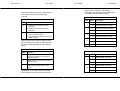
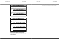
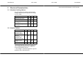
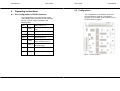
User Manual
CPC-104M
CPC-104M
CAN controller registers. The register
description may be taken from the data sheet
of the NXP SJA1000 CAN controller.
The status register contains the actual state of
CPC-104M.The bits have the following
meaning:
Interrupt Register
Status Register
Bit
0
1
User Manual
Bit
Indication
Value
Description
0
Interrupt of CAN 1 is inactive
1
Interrupt of CAN 1 is active
0
Interrupt of CAN 2 is inactive
1
Interrupt of CAN 2 is active
0
Interrupt of CAN 3 is inactive
1
Interrupt of CAN 3 is active
0
Interrupt of CAN 4 is inactive
1
Interrupt of CAN 3 is active
−
Reserved
0
0: Hardware reset inactive at CAN
controller
1: Hardware reset active at CAN
controller
1
0: CAN controller unmapped into
memory address range
1: CAN controller mapped into memory
address range
2
3
Write accesses to the control register initiate
actions within CPC-104M. The following table
shows the transmitted data and the resulting
action:
4:7
Control Register
Value
Interrupt Enable Register (Write)
Function
Hardware reset of CAN controller. A
write of 0 generates a reset pulse of
adequate length.
Bit
2
Unmap CAN controllers from memory
address range.
1:0
3
Map CAN controllers into memory
address range (write twice to take
effect).
0
3:2
Disable CAN 1 interrupt
11
Enable CAN 1 interrupt
8
Command ignored
10
Disable CAN 2 interrupt
11
Enable CAN 2 interrupt
00, 01
7
Description
10
00, 01
Initialization of the CAN controller and CAN
communication are done by accesses to the
EMS Dr. Thomas Wünsche
Value
Command ignored
EMS Dr. Thomas Wünsche