1
SECTION 3:
WIRING THE HOUSING
3.1 INTRODUCTION
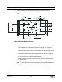
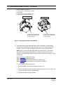
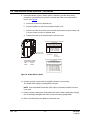
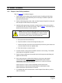
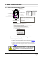
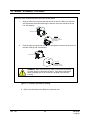
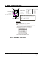
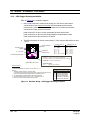
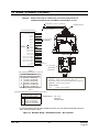
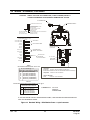
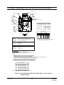
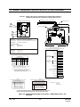
The field wiring for an indoor HD6 is connected at a terminal strip in the housing or
pendant dome. The field wiring for an outdoor HD6 is connected at a CPC connector
(J2) or to fly-leads on the housing. Refer to the information specified in the installation
instructions for wiring connections.
3.1.1
Power
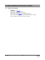
Each camera assembly or scan requires a 24Vac power supply @ 1.1A measured at the
dome.
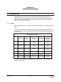
The following table shows the wire gauge required for maximum distances to maintain
24V ac ± 10% at the dome. These wire sizes and distances represent one power source
for one HD6.
Maximum Distance to Dome
AWG
24 VAC
Camera Only
(1.1A)
24 VAC
Blower Only
(0.5A)
24 VAC
Heater & Blower
Only (4A)
24 VAC
Camera plus
Blower (1.6A)
24 VAC
Camera plus
Heater & Blower
(6.0A)
22
65 ft (19m)
150 ft (45m)
Not
Recommended
45 ft (13m)
Not
Recommended
20
100 ft (30m)
235 ft (70m)
Not
Recommended
70 ft (21m)
Not
Recommended
18
160 ft (48m)
375 ft (110m)
62 (19m)
110 (33m)
Not
Recommended
16
260 ft (79m)
600 ft (180m)
99 (30m)
175 (53m)
48 (14m)
14
420 ft (128m)
950 ft (290m)
158 (48m)
280 (85m)
75 (22m)
12
650 ft (198m)
1500 ft (455m)
251 ft (76m)
450 ft (137m)
120 (36m)
The power supply on the scan is isolated so more than one scan can be powered from
the same power source.
Rev. 1.02
19
900.0696
1-Aug-06