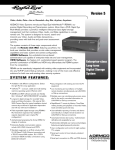
Download KD6 BACK CAN
Transcript
KD6 Series Back Can Modules INSTALLATION MANUAL Rev. B KDMU000823 11/12/03 ISSUE DATE A July 2003 B November 2003 REVISIONS Initial Release (PCN 1540). Added note to Section 3.4 (Manchester Interface) to incorporate information from amendment KDMI000726 (PCN 1622). 2003 HONEYWELL INTERNATIONAL INC. ALL RIGHTS RESERVED HONEYWELL VIDEO SYSTEMS 1305 WATERS RIDGE DRIVE LEWISVILLE, TX 75057 (800) 796-CCTV ALL RIGHTS RESERVED. NO PART OF THIS PUBLICATION MAY BE REPRODUCED BY ANY MEANS WITHOUT WRITTEN PERMISSION FROM HONEYWELL VIDEO SYSTEMS. THE INFORMATION IN THIS PUBLICATION IS BELIEVED TO BE ACCURATE IN ALL RESPECTS. HOWEVER, HONEYWELL VIDEO SYSTEMS CANNOT ASSUME RESPONSIBILITY FOR ANY CONSEQUENCES RESULTING FROM THE USE THEREOF. THE INFORMATION CONTAINED HEREIN IS SUBJECT TO CHANGE WITHOUT NOTICE. REVISIONS OR NEW EDITIONS TO THIS PUBLICATION MAY BE ISSUED TO INCORPORATE SUCH CHANGES. ii Rev. B KDMU000823 11/12/03 FCC COMPLIANCE STATEMENT INFORMATION TO THE USER: THIS EQUIPMENT HAS BEEN TESTED AND FOUND TO COMPLY WITH THE LIMITS FOR A CLASS A DIGITAL DEVICE, PURSUANT TO PART 15 OF THE FCC RULES. THESE LIMITS ARE DESIGNED TO PROVIDE REASONABLE PROTECTION AGAINST HARMFUL INTERFERENCE WHEN THE EQUIPMENT IS OPERATED IN A COMMERCIAL ENVIRONMENT. THIS EQUIPMENT GENERATES, USES, AND CAN RADIATE RADIO FREQUENCY ENERGY AND, IF NOT INSTALLED AND USED IN ACCORDANCE WITH THE INSTRUCTION MANUAL, MAY CAUSE HARMFUL INTERFERENCE TO RADIO COMMUNICATIONS. OPERATION OF THIS EQUIPMENT IN A RESIDENTIAL AREA IS LIKELY TO CAUSE HARMFUL INTERFERENCE IN WHICH CASE THE USER WILL BE REQUIRED TO CORRECT THE INTERFERENCE AT HIS OWN EXPENSE. CAUTION: CHANGES OR MODIFICATIONS NOT EXPRESSLY APPROVED BY THE PARTY RESPONSIBLE FOR COMPLIANCE COULD VOID THE USER’S AUTHORITY TO OPERATE THE EQUIPMENT. THIS CLASS A DIGITAL APPARATUS COMPLIES WITH CANADIAN ICES-003. CET APPAREIL NUMÉRIQUE DE LA CLASSE A EST CONFORME À LA NORME NMB-003 DU CANADA. USERS OF THE PRODUCT ARE RESPONSIBLE FOR CHECKING AND COMPLYING WITH ALL FEDERAL, STATE, AND LOCAL LAWS AND STATUTES CONCERNING THE MONITORING AND RECORDING OF VIDEO AND AUDIO SIGNALS. HONEYWELL VIDEO SYSTEMS SHALL NOT BE HELD RESPONSIBLE FOR THE USE OF THIS PRODUCT IN VIOLATION OF CURRENT LAWS AND STATUTES. iii Rev. B KDMU000823 11/12/03 IMPORTANT SAFEGUARDS 1. READ INSTRUCTIONS – All of the safety and operating instructions should be read before the appliance is operated. 2. RETAIN INSTRUCTIONS – The safety and operating instructions should be retained for future reference. 3. HEED WARNINGS – All warnings on the unit and in the operating instructions should be adhered to. 4. FOLLOW INSTRUCTIONS – All operating and use instructions should be followed. 5. CLEANING – Unplug the unit from the outlet before cleaning. Do not use liquid cleaners or aerosol cleaners. Use a damp cloth for cleaning. 6. ATTACHMENTS – Do not use attachments not recommended by the product manufacturer as they may result in the risk of fire, electric shock, or injury to persons. 7. WATER AND MOISTURE – Do not use this unit near water or in an unprotected outdoor installation, or any area which is classified as a wet location. 8. ACCESSORIES - Do not place this product on an unstable cart, stand, tripod, bracket, or table. The product may fall, causing serious injury to a child or adult and serious damage to the equipment. Use only with a cart, stand, tripod, bracket, or table recommended by the manufacturer, or sold with the product. Any mounting of the product should follow the manufacturer’s instructions and should use a mounting accessory recommended by the manufacturer. Wall or shelf mounting should follow the manufacturer’s instructions and should use a mounting kit approved by the manufacturer. 9. A product and cart combination should be moved with care. Quick stops, excessive force, and uneven surfaces may cause the product and cart combination to overturn. 10. VENTILATION - Slots and openings in the cabinet and the back or bottom are provided for ventilation and to ensure reliable operation of the equipment and to protect it from overheating. These openings must not be blocked or covered. The openings should never be blocked by placing the product on a bed, sofa, rug, or other similar surface. Equipment should never be placed near or over a radiator or heat register. This product should not be placed in a built-in installation, such as a bookcase or rack unless proper ventilation is provided or the manufacturer’s instructions have been adhered to. 11. POWER SOURCES – This product should be operated only from the type of power source indicated on the marking label. If you are not sure of the type of power supplied to your facility, consult your product dealer or local power company. For products designed to operate from battery power or other sources, refer to the operating instructions. 12. GROUNDING OR POLARIZATION – The power supply supplied with this unit may be equipped with a polarized alternating-current line plug (a plug having one blade wider than the other). This plug will fit into the power outlet only one way. This is a safety feature. If you are unable to insert the plug fully into the outlet, try reversing the plug. If the plug should still fail to fit, contact your electrician to replace your obsolete outlet. Do not defeat the safety purpose of the polarized plug. 13. OVERLOADING – Do not overload outlets and extension cords as this can result in a risk of fire or electric shock. iv Rev. B KDMU000823 11/12/03 IMPORTANT SAFEGUARDS, CONTINUED 14. POWER-CORD PROTECTION – Power supply cords should be routed so that they are not likely to be walked on or pinched by items placed upon or against them, paying particular attention to cords and plugs, convenience receptacles, and the point where they exit from the monitor. 15. OBJECT AND LIQUID ENTRY – Never push objects of any kind into this unit through openings as they may touch dangerous voltage points or short-out parts that could result in a fire or electric shock. Never spill liquid of any kind on the unit. 16. SERVICING – Do not attempt to service this unit yourself as opening or removing covers may expose you to dangerous voltage or other hazards. Refer all servicing to qualified service personnel. 17. DAMAGE REQUIRING SERVICE – Unplug the unit from the outlet and refer servicing to qualified service personnel under the following conditions: a. When the power-supply cord or plug is damaged. b. If liquid has been spilled, or objects have fallen into the unit. c. If the unit has been exposed to rain or water. d. If the unit does not operate normally by following the operating instructions. Adjust only those controls that are covered by the operating instructions as an improper adjustment of other controls may result in damage and will often require extensive work by a qualified technician to restore the unit to its normal operation. e. If the unit has been dropped or the enclosure has been damaged. f. When the unit exhibits a distinct change in performance - this indicates a need for service. 18. REPLACEMENT PARTS – When replacement parts are required, be sure the service technician has used replacement parts specified by the manufacturer or have the same characteristics as the original part. Unauthorized substitutions may result in fire, electric shock or other hazards. 19. SAFETY CHECK – Upon completion of any service or repairs to this unit, ask the service technician to perform safety checks to determine that the unit is in proper operating condition. 20. LIGHTNING AND POWER LINE SURGES – For added protection of this unit during a lightning storm, or when it is left unattended and unused for long periods of time, unplug it from the wall outlet and disconnect the cable system. This will prevent damage to the unit due to lightning and power-line surges. 21. HEAT – The product should be situated away from heat sources such as radiators, heat registers, stoves, or other products (including amplifiers) that produce heat. 22. INSTALLATION – Do not install the unit in an extremely hot or humid location, or in a place subject to dust or mechanical vibration. The unit is not designed to be waterproof. Exposure to rain or water may damage the unit. 23. WALL OR CEILING MOUNTING – The product should be mounted to a wall or ceiling only as recommended by the manufacturer. v Rev. B KDMU000823 11/12/03 WARNING • TO REDUCE THE RISK OF FIRE OR ELECTRIC SHOCK, DO NOT EXPOSE THIS PRODUCT TO RAIN OR MOISTURE. • DO NOT INSERT ANY METALLIC OBJECT THROUGH VENTILATION GRILLS. • THIS UNIT MUST BE OPERATED WITH A PROPERLY GROUNDED 3-PIN CONNECTION. NON-OBSERVANCE OF THIS STANDARD PRACTICE MAY RESULT IN A STATIC ELECTRICITY BUILD-UP THAT MAY RESULT IN AN ELECTRIC SHOCK WHEN EXTERNAL CONNECTIONS ARE TOUCHED. CAUTION CAUTION RISK OF ELECTRIC SHOCK DO NOT OPEN CAUTION: TO REDUCE THE RISK OF ELECTRIC SHOCK, DO NOT REMOVE COVER (OR BACK). NO USER-SERVICEABLE PARTS INSIDE. REFER SERVICING TO QUALIFIED SERVICE PERSONNEL. EXPLANATION OF GRAPHICAL SYMBOLS The lightning flash with arrowhead symbol, within an equilateral triangle, is intended to alert the user to the presence of uninsulated "dangerous voltage" within the product's enclosure that may be of sufficient magnitude to constitute a risk of electric shock to persons. The exclamation point within an equilateral triangle is intended to alert the user to the presence of important operating and maintenance (servicing) instruction in the literature accompanying the product. vi Rev. B KDMU000823 11/12/03 DECLARATION OF CONFORMITY To The European Community Council Directive 89/336/EEC ISSUED BY: Ultrak, Inc. 4465 Coonpath Road NW Carroll, OH 43112 USA Tel: (740) 756-9222 Fax: (740) 756-4237 MANUFACTURER: Ultrak, Inc. DATE OF ISSUE: July 31, 1998 TYPE OF EQUIPMENT: CCTV and Security Surveillance Equipment MODEL NUMBER: Domes DD: May be followed by any number of alphanumeric characters. Can not contain an “X” after the seventh field. (Note: “-“ are not considered fields.) Scans* DF, DS, DC, or DH: May be followed by any number of alphanumeric characters. Can not contain an “H” after the seventh field. # D1F, D1S, D1C, or D1H: May be followed by any number of alphanumeric characters. Can not contain an “X after the seventh field. SmartScan III’s* 39, 3A, 3B, or 3C: May be followed by any number of alphanumeric characters. Must contain a “C” in the seventh field or after. UltraDome KD6* KD6 May be followed by any number of alphanumeric characters. Must contain a “P” in the seventh field. KDS May be followed by any number of alphanumeric characters. KD6 Z-Series* KDZ May be followed by any number of alphanumericcharacters. ZD2 Series* ZD2 May be followed by any number of alphanumeric characters. Yokes* FX-X1, SM-X1, FX9-X1, FX9-X2, SM9-X1, SM9-X2 Power Supply TR-24/D/CE, TR-24/WSPX *Standard EN60065 does not apply. 2#Standard 87/404/EEC Simple PressureDirective does not apply. Pressure is less than 0.5273 kg/cm . STANDARDS TO WHICH CONFORMITY IS DECLARED: EN50081-1 Emissions Standard, and EN50082-1 Immunity Standard. EN55022 Radiated, Class A, EN55022 Conducted, Class A,IEC-1000-4-2, ESD, IEC-1000-4-3, RF Fields, IEC-1000-4-4, Fast Transients/Burst. EN60065 - Safety Requirements for Audio, video and similar electronics apparatus. Ultrak, Inc. hereby declares that the models specified above conform to the directive and standard as speci fied. Donald L. Stephenson Compliance Engineer 517775-5 Rev. M March 5, 2002 vii Rev. B KDMU000823 11/12/03 IMPORTANT NOTICE All companies make changes and improvements in their products. Because this product can be set up to interface with equipment not manufactured by Honeywell Video Systems, there is a possibility that the interface protocols may have changed since Honeywell Video Systems tested this product with the interfacing equipment. Therefore, this unit may not be currently compatible with equipment produced by other manufacturers. The existence of past successful installations proves our intent to provide equipment compatible with other manufacturers, but does not guarantee success. Honeywell Video Systems recommends purchasing a single unit for bench testing prior to purchasing and installing this product in quantity. Should any problems occur, Honeywell Video Systems will provide technical support (at the user’s expense) to analyze the interface protocols of your system. The end user must agree to give Honeywell Video Systems reasonable access to the system in order to study and correct the protocol incompatibility. In the event that Honeywell Video Systems is unable to make the units work together in the system, we will accept the return of any Honeywell Video Systems products associated with the installation and refund the amounts paid for these products. Because Honeywell Video Systems recommends bench testing the equipment prior to installation, we will not be liable for any installation cost, lost revenues, or other cost resulting from the incompatibility. viii Rev. B KDMU000823 11/12/03 TABLE OF CONTENTS SECTION 1: INTRODUCTION ..................................................................................................................... 1 1.1 PRODUCT DESCRIPTION .......................................................................................................... 1 1.2 RECOMMENDED CABLING AND CONNECTORS..................................................................... 1 SECTION 2: BASIC INSTALLATION .......................................................................................................... 3 2.1 DROPPED CEILING BACK CAN MODULE................................................................................. 3 2.2 HARD CEILING BACK CAN MODULE ........................................................................................ 5 2.3 PENDANT DOME BACK CAN MODULE ..................................................................................... 7 2.4 KD6 RUGGED DOME BACK CAN MODULE ............................................................................ 10 2.5 WEATHER DOME BACK CAN MODULE .................................................................................. 15 SECTION 3: WIRING THE BACK CAN MODULE .................................................................................... 19 3.1 INTRODUCTION ........................................................................................................................ 19 3.1.1 Power............................................................................................................................. 19 3.1.2 Control Data................................................................................................................... 20 3.1.3 Video.............................................................................................................................. 22 3.1.4 Alarm.............................................................................................................................. 22 3.2 WIRING – STANDARD............................................................................................................... 23 3.2.1 Dropped / Hard Ceiling Installation ................................................................................ 23 3.2.2 Pendant Dome Installation............................................................................................. 26 3.2.3 KD6 Rugged Dome Installation ..................................................................................... 28 3.2.4 Weather Dome Installation ............................................................................................ 29 3.3 WIRING – CAT5 AND UTC OPTION ......................................................................................... 32 3.3.1 Dropped Ceiling / Hard Ceiling / Pendant Dome Installation......................................... 32 3.3.2 KD6 Rugged Dome Installation ..................................................................................... 36 3.3.3 Weather Dome Installation ............................................................................................ 38 3.4 WIRING – MANCHESTER INTERFACE.................................................................................... 41 3.4.1 Dropped Ceiling / Hard Ceiling / Pendant Dome / Weather Dome Installation ............. 41 3.4.2. KD6 Rugged Dome Installation ..................................................................................... 44 ix Rev. B KDMU000823 11/12/03 TABLE OF FIGURES Figure 1: Dropped Ceiling Back Can Installation ......................................................................................... 3 Figure 2: Hard Ceiling Back Can Installation ............................................................................................... 5 Figure 3: Pendant Dome Back Can Installation ........................................................................................... 7 Figure 4: Safety Cable Installation ............................................................................................................. 10 Figure 5: Installing Conduit Fitting In Top Dome ....................................................................................... 11 Figure 6: Mounting Bracket Hole Detail ..................................................................................................... 12 Figure 7: Changing Orientation of the Bracket........................................................................................... 13 Figure 8: Heater/Blower Option ................................................................................................................. 14 Figure 9: Safety Cable Installation ............................................................................................................. 16 Figure 10: Standard Wiring – Dropped / Hard Ceiling Installation ............................................................. 24 Figure 11: Installing Top Plate in Back Can Module.................................................................................. 25 Figure 12: Standard Wiring – Pendant Dome ............................................................................................ 27 Figure 13: Standard Wiring – KD6 Rugged Dome Back Can Installation.................................................. 28 Figure 14: Standard Wiring – KD6 Weather Dome – No Connector ......................................................... 30 Figure 15: Standard Wiring – KD6 Weather Dome –14-pin Connector..................................................... 31 Figure 16: CAT5 and UTC Option Wiring – Hard / Dropped / Pendant Domes......................................... 35 Figure 17: CAT5 or UTC Option – KD6 Rugged Dome ............................................................................. 37 Figure 18: CAT5 or UTC Option – KD6 Weather Dome – No Connector.................................................. 39 Figure 19: CAT5 or UTC Option – KD6 Weather Dome – 14-pin Connector ............................................ 40 Figure 20: Manchester Interface Wiring – Dropped Ceiling / Hard Ceiling / Pendant ............................... 43 Figure 21: Manchester Interface Wiring – KD6 Rugged Dome ................................................................. 44 x Rev. B KDMU000823 11/12/03 SECTION 1: INTRODUCTION 1.1 PRODUCT DESCRIPTION An UltraDome KD6 is a pan and tilt mechanism containing a camera and lens that is controlled remotely by an operator using a Diamond series, Maxpro series, Pelco (P and D code only), American Dynamics Manchester, Burle Biphase, or VCL control system. The UltraDome KD6 is housed in a back can for dropped or hard ceiling applications or in a pendant dome for indoor applications. The KD6 is housed in a Weather Dome or Rugged Dome for outdoor applications. The whole assembly is often referred to as a "dome". The pan and tilt mechanism with camera and lens is often referred to as a "scan". The indoor pendant top dome can be mounted on a Honeywell Video Systems indoor pendant ceiling dome mount or indoor wall dome mount. The weather dome can be mounted on a Honeywell Video Systems outdoor wall mount, pendant mount, roof mount, or parapet mount. This installation guide provides instructions for mounting the different types of back can modules. Refer to the User Manual for operation and programming information. 1.2 RECOMMENDED CABLING AND CONNECTORS Type Recommended Cable Part Number Maximum Distance Video Coax, RG-59/U, 75 Ohms BNC Connector, Crimp On for RG-59/U BNC Connector, Screw Type for RG-59/U 849518-0054 842374-0194 842374-0391 1000 Feet (305 Meters) Data Twisted Shielded Pair, RS-422 Data 849518-0334 4000 Feet (1219 Meters) Power 18 AWG 2-Conductor , Vinyl Jacket 849518-0336 See Gauge Chart for Each Unit Alarm Belden 8205 849518-0217 10,000 Feet UTC Option Coax, RG-59/U, 75 Ohms BNC Connector, Crimp On for RG-59/U BNC Connector, Screw Type for RG-59/U 849518-0054 842374-0194 842374-0391 1000 Feet (305 Meters) CAT5 Option CAT5 Cabling 1 twisted pair for data 1 twisted pair for video 849518-0399 DIP Switch Selectable 0-300 (0-90 Meters) 300-600 (90-180 Meters) 600-900 (180-270 Meters) 900-1200 (270-365 Meters) 1200-1500 (365-455 Meters) CAT5 Receiver required at monitor 843216-0953 1500 Feet (455 Meters) Digital Interface Option CAT5 Cable with an RJ-45 Connector for 10baseT or 100baseT Ethernet 1 Rev. B KDMU000823 11/12/03 NOTES: 2 Rev. B KDMU000823 11/12/03 SECTION 2: BASIC INSTALLATION 2.1 DROPPED CEILING BACK CAN MODULE Installation must be performed by qualified technical personnel and must be in accordance with all national and local mechanical and electrical codes. Perform the following steps to install a dropped ceiling back can module. Refer to Figure 1. SAFETY CABLE TIE POI NT (METAL TAB WITH HOLE ON SIDE OF CAN) CONNECT SECURELY TO BUILDING SUPPORT STRUCTURE BACK CAN MODULE APPROX 5. 00 (127) SPRING LATCH (RELEASES TOP PLATE) SCAN ALIGNMENT ST UDS BOTTOM DOME MOUNTING POSTS (3 PLACES) CUT-OUT IN CEILING TILE 7 5/8” DIA. (193.8) CABLE CLAMP DROPPED CEILING PLATE WING TAB (3 PLACES) TURN SCREW CLOCKWISE TO EXTEND SUPPORT CLAMPS AND SECURE DOME TO CEILING (TYPICAL 3 PLACES) ATTACH LANYARD TO BOTTOM CUSTOMER 2 FT SPAN DROPPED CEILING GRID SUPPORTS .62 (15.7) DRO PPED CEILING TILE Figure 1: Dropped Ceiling Back Can Installation 1. Select the location(s) of the back can module(s). Each KD6 requires a 24Vac ± 10% power source. Some back can modules are provided with a 120Vac, 60 Hz to 24Vac or 220Vac, 50/60 Hz to 24Vac power transformer. If a transformer is not provided, ensure a 24Vac @ 1.1A power source is available. 2. Remove the ceiling panel (2’x4’ or 2’x2’) at the dome location. 3. Place the ceiling tile on the dropped ceiling plate. Trim the ceiling tile so you can press the ceiling tile into the dropped ceiling plate. 4. Cut a hole in the ceiling tile flush with the hole in the center of the plate. 3 Rev. B KDMU000823 11/12/03 2.1 DROPPED CEILING BACK CAN MODULE, CONTINUED 5. Secure a safety cable (supplied by installer) to a building support structure. Honeywell Video Systems recommends using 3/32” plastic coated aircraft cable (part 849518-0311) and looping sleeves (part 849511-0057). The crimping tool required to secure the recommended looping sleeve is part number 941508-0049. These parts can be ordered from the Honeywell Video Systems parts department. 6. Place the back can module in the ceiling mount. The space between the wing tabs on the back can module and the back can module flange should be greater than the thickness of the ceiling tile and the mount. Make sure the wing tabs on the back can module are staggered so the tabs are not at the same height. Position the wing tabs flat against the back can module. Push the back can module through the hole in the ceiling tile and the mount (some jostling is required). Using a screwdriver, turn the three screws in the back can module clockwise to rotate the tabs out and tighten the tabs against the ceiling mount. 7. Attach the safety cable (from the building support structure) to the back can module by threading the cable through a looping sleeve, through the hole in the tab (beside the conduit fitting) on the back can module, and then through the looping sleeve again. Secure by crimping the looping sleeve. The safety cable tab on the back can module can be rotated as needed for clearance in the ceiling. 8. Place the ceiling tile with the plate and the back can module on the ceiling support grid. 9. Refer to Section 3 for wiring instructions. Refer to Section 3.2 for standard wiring. Refer to Section 3.3 for CAT5 or UTC wiring. Refer to Section 3.4 for Manchester Interface wiring. 4 Rev. B KDMU000823 11/12/03 2.2 HARD CEILING BACK CAN MODULE Installation must be performed by qualified technical personnel and must be in accordance with all national and local mechanical and electrical codes. Perform the following steps to install a KD6 hard ceiling dome. Refer to Figure 2. SAFETY CABLE TI E POI NT (METAL TAB WITH HOLE ON SIDE OF CAN) CONNECT SECURELY TO BUILDING SUPPORT STRUCTURE BACK CAN MODULE Compass Tool (part number 518058-2120) Hole Pin APPRO X 5.00 (127) SPRING LATCH (RELEASES TOP PLATE) SCAN ALIGNMENT ST UDS SEAL CUT-OUT USING TAPE OR PLASTIC CHANNEL (SUPPLIED BY INSTALLER) CUT-OUT IN CEILING 7 5/8” DIA. (193.8) BOTTOM DOME MOUNTING PO STS (3 PLACES) CABLE CLAMP WI NG TAB (3 PLACES) DRYWALL CEILING TURN SCREW CLOCKWISE TO EXTEND SUPPORT CLAMPS AND SECURE DOME TO CEILING (TYPICAL 3 PLACES) ATTACH LANYARD TO BOTTOM Figure 2: Hard Ceiling Back Can Installation 1. Select the location(s) of the back can module(s). Each KD6 requires a 24Vac ±10% power source. Some back can modules are provided with a 120Vac, 60 Hz to 24Vac or 220Vac, 50/60 Hz to 24Vac power transformer. If a transformer is not provided, ensure a 24Vac power source is available. 2. Cut a 7–5/8" (193.8mm) diameter hole in the ceiling using the compass tool (part number 518058-2120) provided with the hard ceiling back can module. See Figure 2. a. Drill a 1/8” diameter hole in the ceiling where the center of your dome is to be located. b. Insert the pin on the tool in the drilled hole. c. Scribe a line on the ceiling using the hole in the other end of the tool. d. Cut out the hole for the back can module using the scribed line. 5 Rev. B KDMU000823 11/12/03 2.2 HARD CEILING BACK CAN MODULE, CONTINUED 3. If the ceiling is drywall or plaster, Honeywell Video Systems recommends sealing the entire perimeter of the ceiling cut-out with tape or plastic channel (provided by installer). This prevents dust and material from dropping from ceiling. 4. Secure a safety cable (supplied by installer) to a building support structure in the ceiling. Honeywell Video Systems recommends using 3/32" plastic coated aircraft cable (part number 849518-0311) and splicing sleeves (part number 849511-0057). The crimping tool required to secure the recommended splicing sleeve is part number 941508-0049. These parts can be ordered from the Honeywell Video Systems parts department. 5. Attach the safety cable (from the building support structure) to the back can module by threading the cable through a splicing sleeve, through the hole on the metal tab (beside conduit fitting) on the back can module, and then through the splicing sleeve again. Secure by crimping the splicing sleeve. The safety cable tab can be rotated as required for clearance in ceiling. 6. Insert the back can module in the ceiling. Make sure the space between the wing tabs on the back can module and the back can module flange is greater than the thickness of the ceiling. Make sure the wing tabs on the back can module are staggered so the tabs are not at the same height. Position the wing tabs flat against the back can module. Insert the back can module through the hole in the ceiling (some jostling is required). Using a Phillips screwdriver, turn the three screws in the back can module clockwise to rotate the tabs out and tighten the tabs against the ceiling. 7. Refer to Section 3 for wiring information. Refer to Section 3.2 for standard wiring. Refer to Section 3.3 for CAT5 or UTC wiring. Refer to Section 3.4 for Manchester Interface wiring. 6 Rev. B KDMU000823 11/12/03 2.3 PENDANT DOME BACK CAN MODULE Installation must be performed by qualified technical personnel and must be in accordance with all national and local mechanical and electrical codes. Perform the following steps to install a KD6 pendant dome on a Honeywell Video Systems indoor wall or ceiling pendant dome mount: INSERT PIN FOR SAFETY CABLE BLACK NIPPLE SAFETY CABLE INSTALLATION MOUNTING HOLES (3 PLACES) TOP PENDANT DOME ATTACH THE SAFETY CABLE TO A BUILDING SUPPORT STRUCTURE SPLICING SLEEVE SAFETY CABLE SPRING LATCH (RELEASES TOP PLATE) SPLICING SLEEVE SCAN ALIGNMENT STUDS LOOP AROUND 1/4” DIA x 1-3/4” LG. PIN INSERTED IN TOP OF DOME DETAIL A (SUPPLIED BY INSTALLER) BOTTOM DOME MOUNTING POSTS (3 PLACES) Figure 3: Pendant Dome Back Can Installation 1. Select the location of the dome(s). Each KD6 requires a 24Vac ±10% power source. Some pendant domes are provided with a 120Vac, 60 Hz to 24Vac or 220Vac, 50/60 Hz to 24Vac power transformer. If a transformer is not provided, ensure a 24Vac @ 1.1A power source is available 2. Install the mount using the instructions provided with your specific mount. 7 Rev. B KDMU000823 11/12/03 2.3 PENDANT DOME BACK CAN MODULE, CONTINUED 3. Run the field wiring (control data, video, power, and alarm) and a safety cable (secured to a building support structure) through the mount. Honeywell Video Systems recommends using 3/32” plastic coated aircraft cable (part number 849518-0311) and looping sleeves (part number 849511-0057) for the safety cable. (Refer to Detail A in Figure 3.) The safety cable materials may be purchased from the Honeywell Video Systems parts department. The wiring and safety cable must extend at least one foot past the pipe for wiring purposes. Refer to Section 3 for detailed wiring information. CAUTION: If installing the pendant dome on a threaded mount, do not attach the safety cable to a building support structure until after the dome is threaded onto the mount. 4. Locate the top dome decorative cover flange supplied with the mount. Refer to the instructions provided with your specific mount. Slide the flange over the cabling and up onto the mount. Secure the flange temporarily (use tape) to the mount out of the way of the cabling. 5. Locate the pendant top dome. a. Using a screwdriver, remove the two hairpin clips securing the ¼” pin in the black nipple. Slide the ¼” pin out of the black nipple. Remove the black dust cover plug by inserting a screwdriver in the slot of the plug and pulling the plug out of the nipple. Set the clips and pin aside. (They will be reinstalled later.) Discard the dust cover plug. b. Remove the top plate (located in the top of the pendant top dome) by pressing the spring latch on the top plate until the top plate is released, then lower the top plate down. c. Insert the field wiring (data, power, video, and alarm) from the mount through the black nipple on the pendant top dome. d. Insert the ¼” pin in the ¼” holes in the black threaded nipple on the pendant top dome. e. Secure the pin on each end using the two hairpin clips. f. Route the safety cable (attached to the building support structure) through a splicing sleeve, around the pin in the top dome, and then through the sleeve again. Secure the safety cable by crimping the sleeve using a crimping tool. See Figure 3, Detail A. 8 Rev. B KDMU000823 11/12/03 2.3 PENDANT DOME BACK CAN MODULE, CONTINUED g. Carefully slide the black nipple on the pendant top dome into the mounting pipe. If installing the dome on a threaded mount, thread the dome into the mount at this time then connect the safety cable to a building support structure. CAUTION: Do not force the dome into the mount; the threads on the dome are plastic and could be damaged if force is used. h. Line up the three mounting holes on the top dome with the holes in the mount piping. Use the three self-tapping hex head screws supplied with the mount to secure the dome to the mount i. Slide the decorative cover flange on the mount (step 4 above) over the black nipple on the top dome. 6. Connect the field wiring to the top dome mounting plate (removed in step 5 above). Refer to Section 3 for wiring information. Refer to Section 3.2 for standard wiring. Refer to Section 3.3 for CAT5 or UTC wiring. Refer to Section 3.4 for Manchester Interface wiring. 9 Rev. B KDMU000823 11/12/03 2.4 KD6 RUGGED DOME BACK CAN MODULE Installation must be performed by qualified technical personnel and must be in accordance with all national and local mechanical and electrical codes. Perform the following steps to install a rugged dome back can module. 1. Select the location(s) of the dome. Each KD6 requires a 24Vac ±10% @ 1.1A power source. The heater/blower option requires an additional 24Vac @ 4A power source. The blower option requires an additional 24Vac @ 0.5A power source. 2. Secure a safety cable (supplied by installer) to a building support structure. Honeywell Video Systems recommends using 3/32" plastic coated aircraft cable (part 849518-0311) and splicing sleeves (part 849511-0057). The crimping tool required to secure the recommended splicing sleeve is part number 941508-0049. These parts can be ordered from the Honeywell Video Systems parts sales department. SAFETY CABLE INSTALLATION ATTACH THE SAFETY CABLE TO A BUILDING SUPPORT STRUCTURE SPLICING SLEEVE SAFETY CABLE SPLICING SLEEVE LOOP THROUGH HOLE IN MOUNTING BRACKET 3. Attach the safety cable from the building structure to the mounting bracket. Route the safety cable through one side of a splicing sleeve (not supplied), then through the hole in the side of the mounting bracket, then through the other side of the splicing sleeve. Secure the safety cable by crimping the splicing sleeve. (SAFETY CABLE SUPPLIED BY INSTALLER) Figure 4: Safety Cable Installation 4. Locate the top dome and set the jumpers and switches as applicable on the circuit board. Refer to Section 3 for wiring information. Refer to Section 3.2 for standard wiring. Refer to Section 3.3 for CAT5 or UTC wiring. Refer to Section 3.4 for Manchester Interface wiring. 5. After completing wiring, continue basic installation for KD6 Rugged Dome back can module. 10 Rev. B KDMU000823 11/12/03 2.4 KD6 RUGGED DOME BACK CAN MODULE, CONTINUED 6. Install a ¾” conduit fitting (not supplied) in the hole on the top dome. Place the supplied washer between the hole in the top dome and the conduit fitting to prevent leakage. Tighten the conduit nut to secure the fitting to top dome and prevent leakage. Conduit Fitting Conduit Nut Top Dome Washer Figure 5: Installing Conduit Fitting In Top Dome 11 Rev. B KDMU000823 11/12/03 2.4 KD6 RUGGED DOME BACK CAN MODULE, CONTINUED 7. Mount the top dome to a ceiling support structure or wall support structure. The mounting hardware is supplied by the installer. There are four sets of mounting holes. 1.930 .313 TYP. 3.500 .437 TYP. .300 TYP. 1.150 3.500 2.625 1.000 1.150 2.625 6. 500 Figure 6: Mounting Bracket Hole Detail a. The mounting bracket can be positioned between 0°-45° or 45°-90° depending on the orientation of the mounting bracket on the top dome. To change the orientation of the bracket, remove the four nuts, lock washers and bolts that secure the bracket to the top dome. Flip the bracket over and secure the bracket to the top dome using the four nuts, lock washers, and bolts. b. The mounting bracket can be repositioned by loosening the four nuts (two on each side) inside the top dome and sliding the bracket along the slot. Tighten the four nuts to secure the bracket at the desired angle. c. NOTE: Secure the mount to the wall or ceiling using the appropriate hardware for the mounting surface. The mounting bracket can be at any angle from 0° to 90° with respect to the top dome. The top dome must be positioned horizontal and parallel with the floor. 12 Rev. B KDMU000823 11/12/03 2.4 KD6 RUGGED DOME BACK CAN MODULE, CONTINUED To change orientation of bracket: 1. Remove nuts, lockwashers, and bolts 2. Flip bracket 3. Insert bolts (4) in slots and hole, and 4. Secure with lockwashers and nuts. 0°-90° 0°-45° Loosen nuts (2 each side) to slide bracket along slot to change angle Loosen nuts (2 each side) to slide bracket along slot to change angle Figure 7: Changing Orientation of the Bracket 8. Route the field-run wiring (data, KD6 power, video, and heater or blower power) through the conduit fitting to the appropriate position on the terminal strips in the top dome. The terminal strips are labeled to show the function of each position. NOTE: Do not connect the data cable shield at the terminal strip. The terminal strips TB1 and TB2 accept 18-24 AWG wire. If larger or smaller field-run wire is required, an 18-24 AWG wire must be spliced onto the field wire for insertion into the terminal strip. Refer to Section 3 for wiring information. Refer to Section 3.2 for standard wiring. Refer to Section 3.3 for CAT5 or UTC wiring. Refer to Section 3.4 for Manchester Interface wiring. Refer to Figure 8 if the heater/blower or blower option is installed. a. Flip up the tab on the terminal strip. b. Strip the insulation on the wire back approximately 7/16”. c. Insert the wire fully in the hole on the terminal strip to ensure a good contact and to ensure it does not short to adjacent wires. d. Push the tab down to secure the wire. 13 Rev. B KDMU000823 11/12/03 2.4 KD6 RUGGED DOME BACK CAN MODULE, CONTINUED 9. If the heater/blower option or blower option is installed, route the 24Vac wiring through the conduit fitting and connect at terminal strip TB4 on the heater/blower board. See Figure 8. a. Loosen the screw on the terminal strip. b. Strip the insulation on the wire back approximately 7/16”. c. Insert the wire fully in the hole on the terminal strip to ensure a good contact and to ensure it does not short to adjacent wires. d. Tighten the screw on the terminal strip to secure the wire. HEATER/BLOWER POWER REQUIREMENTS 24VAC @ 4A 24VAC POWER CONNECTIONS 24 VAC HEATER POWER MAXIMUM WIRE LENGTHS AWG MAX. DISTANCE TO DOME 19 FEET (5.7 METERS) 22 30 FEET (9 METERS) 20 50 FEET (15 METERS) 18 75 FEET (23 METERS) 16 120 FEET (37 METERS) 14 190 FEET (58 METERS) 12 THERMOSTAT: ON 70 F OFF 90 F OUTPUT 96W BLOWER POWER REQUIREMENTS 24VAC @ 0.5A Heater/Blower Option Power Terminal Strip TB4-1 24VAC TB4-2 24VAC 24 VAC HEATER POWER MAXIMUM WIRE LENGTHS AWG MAX. DISTANCE TO DOME 150 FEET (45 METERS) 22 235 FEET (70 METERS) 20 375 FEET (110 METERS) 18 600 FEET (180 METERS) 16 950 FEET (290 METERS) 14 1500 FEET (455 METERS) 12 Figure 8: Heater/Blower Option 10. Connect the video coaxial cable to the BNC connector in the back can module. The installer must supply the mating BNC connector. NOTE: If the CAT5 option is installed, the BNC connector is not used. 11. Feed the excess cabling from the terminal strips and the video cabling back through the conduit fitting and tighten the cable clamp on the fitting (if applicable). 12. Refer to the KD6 Series User Manual to install the scan. 14 Rev. B KDMU000823 11/12/03 2.5 WEATHER DOME BACK CAN MODULE Installation must be performed by qualified technical personnel and must be in accordance with all national and local mechanical and electrical codes. Perform the following steps to install a KD6 weather dome on a Honeywell Video Systems outdoor mount with an ELL conduit fitting or an MDW1210W mount. 1. Select the location of the dome and ensure a 24Vac ± 10% power source is available. An additional 24Vac @ 4A power source is required for the heater/blower installed in the weather dome. 2. Install the mount using the instructions provided with your specific mount. Run the required field wiring and safety cable through the mount for the KD6 weather dome. The field wiring and safety cable are the responsibility of the installer. Honeywell Video Systems recommends using 3/32” plastic coated aircraft cable, part number 849518-0311, for the safety cable. NOTE: Only the weather or pressurized domes with No Connector is compatible with the MDW1210W mount. 3. Refer to Section 3 for wiring information. Refer to Section 3.2 for standard wiring. Refer to Section 3.3 for CAT5 or UTC wiring. Refer to Section 3.4 for Manchester Interface wiring. 15 Rev. B KDMU000823 11/12/03 2.5 WEATHER DOME BACK CAN MODULE, CONTINUED 4. Locate the 1-1/2” NPT conduit nut shipped loose with the mount. Thread the conduit nut onto the black threaded nipple on the weather dome with the teeth on the nut away from the dome. 5. Wrap Teflon tape (installer supplied) around the black threaded nipple on the weather dome. SAFETY CABLE INSTALLATION (SUPPLIED BY INSTALLER) 6. Attach the safety cable from the building structure to the weather dome. Use a looping sleeve, (part number 849511-0057) (not supplied) to secure the safety cable. Route the safety cable through one side of the looping sleeve, around the pin in the weather dome, and through the other side of the looping sleeve. Secure the safety cable by crimping the looping sleeve. (See Figure 9). ATTACH THE SAFETY CABLE TO A BUILDING SUPPORT STRUCTURE SPLICING SLEEVE SAFETY CABLE SPLICING SLEEVE The crimp tool required for the looping sleeve is part number 941508-0049. LOOP AROUND PIN IN BLACK NIPPLE OF WEATHER DOME Figure 9: Safety Cable Installation 7. Install the weather dome on the mount. Carefully push the cabling from the weather dome up into the mount and thread the weather dome into the threaded pipe on the mount. CAUTION: Do not force the dome into the threaded pipe. The nipple on the weather dome is plastic and the threads on the nipple could be stripped if force is used. 8. After the weather dome is threaded into the mount as far as it will go, thread the conduit nut on the weather dome up against the mount and tighten. Seal the joint between the mount and the black nipple on the weather dome with Dow RTV 3145. 9. Connect mating connector J2 (field wiring) in the mount to connector P2 on the weather dome (on 14-pin connector version only.) 16 Rev. B KDMU000823 11/12/03 2.5 WEATHER DOME BACK CAN MODULE, CONTINUED 10. Replace the cover on the mount conduit box or access hole cover plate on the MDW1210W mount using the two screws removed when installing the mount. CAUTION: Ensure all field wiring is pushed back into the mount pipe. Ensure the gasket between the conduit box or mount and the cover is seated properly. 11. Seal all joints and screws in the outdoor mount. Use Dow 3145 RTV for Allen head screws, bolts, joints, and all mounting surfaces. Use Teflon tape for threaded joints. CAUTION: All joints, bolts, and screws in the mount must be sealed to prevent water (moisture) from entering the weather dome. 12. Refer to the KD6 Series User Manual to install the scan. 17 Rev. B KDMU000823 11/12/03 NOTES: 18 Rev. B KDMU000823 11/12/03 SECTION 3: WIRING THE BACK CAN MODULE 3.1 INTRODUCTION The field wiring for an indoor UltraDome KD6 is connected at a terminal strip in the back can or pendant dome. The field wiring for an outdoor UltraDome KD6 is connected at a CPC connector (J2) on the top dome. Refer to the information specified in the installation instructions for wiring connections. 3.1.1 Power Each scan requires a 24Vac power supply @ 1.1A. The following table shows the wire gauge required for maximum distances to maintain 24V ac ± 10% at the power supply. These wire sizes and distances represent one power source for one KD6. 24V ac ± 10% at Power Supply AWG Maximum Distance 22 60 Feet (18 Meters) 20 95 Feet (29 Meters) 18 150 Feet (45 Meters) 16 240 Feet (73 Meters) 14 390 Feet (118 Meters) 12 625 Feet (190 Meters) The power supply on the scan is isolated so more than one scan can be powered from the same power source. CAUTION: Installation must be performed by a qualified electrician. The proper wire size for the distance and the number of scans must be determined to maintain 24V ac at each scan. Do not use the above table for this configuration. 19 Rev. B KDMU000823 11/12/03 3.1 FIELD WIRING, CONTINUED 3.1.2 Control Data NOTE: If the UTC option is installed, the data lines are not connected at the terminal strip, data is transmitted over the coaxial cable to the BNC connector. A UCT-100 series transmitter is required to transmit data over coaxial cable to the KD6. The UTC option cannot be used in conjunction with iPro protocol. On standard KD6 units, a shielded twisted-pair RS-485 cable is required. If using iPro protocol in the scan, two shielded twisted-pair cable are required or one twistedpair if the RX+ and TX+ are jumpered together and the RX- and TX- are jumpered together. See Figure 10 for jumper settings. For 2-wire communication, set Jumpers W3 and W4 in positions 1 & 2. On KD6 units with the CAT5 option, one twisted-pair of the CAT5 cable is required for data. If using iPro protocol in the scan and the CAT-5 option, one twisted pair is required with the RX+ and TX+ jumpered together and the RX- and TX- jumpered together. The data lines can be home-run wired or daisy-chain wired from the control output. Home-run wiring is one scan per control output and the scan must be terminated. Daisy-chain wiring is up to 32 scans per data run with the control output at one end of the run or in the middle of the run. If the control output is at the end of the data run, the last scan on the end of the data run must be terminated and all intermediate scans unterminated. If the control output is in the middle of the data run, the last scan on both ends must be terminated, and all intermediate scans unterminated. Jumpers W1 and W2 on the circuit board in the back can or pendant dome are used to terminate the data. Refer to the following diagram. The data cable shield should be carried through all units by connecting the cable shields together, but do not connect the cable shield at the dome. Connect the cable shield at the control unit. 20 Rev. B KDMU000823 11/12/03 3.1 FIELD WIRING, CONTINUED MAXIMUM DISTANCE = 4000 FEET MAXIMUM DOMES = 32 RX+ RX– RX+ RX– JUMPER W1 JUMPER W2 TERMINATED JUMPER W1 JUMPER W2 UNTERMINATED RX+ RX– TX+ TX– RX+ RX– RX+ RX– JUMPER W1 JUMPER W1 JUMPER W1 JUMPER W2 JUMPER W2 JUMPER W2 UNTERMINATED UNTERMINATED TERMINATED CONTROL OUTPUT MAXIMUM DISTANCE = 4000 FEET MAXIMUM DOMES = 32 RX+ RX– TX+ TX– CONTROL OUTPUT RX+ RX– RX+ RX– RX+ RX– JUMPER W1 JUMPER W1 JUMPER W1 JUMPER W1 JUMPER W1 JUMPER W2 JUMPER W2 JUMPER W2 JUMPER W2 JUMPER W2 UNTERMINATED UNTERMINATED UNTERMINATED UNTERMINATED UNTERMINATED Home Run Wiring Control Output Daisy Chain Wiring KD6 Control Output KD6 KD6 TX+ RX+ TX+ RX+ RX+ TX- RX- TX- RX- RX- NOTE: If the polarity on the data wiring is reversed, the scan automatically corrects the polarity. This feature does not apply on units set for VCL, Pelco P, Pelco D, or iPro protocol – the data must be wired TX+ to RX+ and TX- to RX-. 21 Rev. B RX+ RX– KDMU000823 11/12/03 3.1 FIELD WIRING, CONTINUED 3.1.3 Video NOTE: If the CAT5 option is installed, the video is run on CAT5 cable (twisted pair) and the BNC connector is not used. A CAT5 receiver is required at the monitor. The video on the CAT5 cable cannot be daisy-chained. RG-59/U coaxial cable is recommended for cable runs less than 1500 feet. If the UTC option is installed, the maximum recommended cable length is 1000 feet. If the CAT5 option is installed, 1 twisted-pair of the CAT5 cabling is required for video. The video must be terminated in 75 ohms at the last video device. If the video is not terminated or double terminated, the resulting picture is poor and ghosting is displayed. 3.1.4 Alarm Connect a twisted-pair cable from each peripheral alarm contact to each input at the alarm number terminal and the alarm common terminal. The alarm is a dry contact between the alarm terminal and the common terminal. 22 Rev. B KDMU000823 11/12/03 3.2 WIRING – STANDARD 3.2.1 Dropped / Hard Ceiling Installation Refer to Figure 10 for installation diagram. 1. The top plate in the back can module can be lowered for ease of installing the field wiring. Pull the spring latch on the plate away from the back can module to release the plate and then lower the plate down. 2. Feed the field wiring (data, power, video, and alarm inputs) through the back can module and then through the cable clamp on the top plate. 3. Install the 24Vac power wires, data wires, and alarm wires on the correct positions on terminal strip TB1 and TB2 in the back can module. Refer to Figure 3. The terminal strip is labeled to show the function of each position. NOTE: Do not connect the data cable shield at the terminal strip. The terminal strip accepts 18-24AWG wire. If larger or smaller field-run wire is required, an 18-24 AWG wire must be spliced onto the field wire for insertion into the terminal strip. a. Flip up the tab on the terminal strip. b. Strip the insulation on the wire back approximately 7/16”. c. Insert the wire fully in the hole on the terminal strip to ensure a good contact and to ensure it does not short to adjacent wires. d. Push the tab down to secure the wire. 4. Connect the video coaxial cable to the BNC connector in the back can module. The installer must supply the mating BNC connector. 5. Feed the excess cabling from the terminal strips back through the cable fitting and tighten the cable clamp. 6. If this is the last dome in a daisy-chain wiring loop, the receive and transmit communication lines must be terminated. All intermediate domes must be unterminated. If this is the only dome on a data line, the receive and transmit communication lines must be terminated. Install Jumper W1 and W2 on pins 1 and 2 (terminated) to terminate the data. Install Jumper W1 and W2 on pins 2 and 3 (unterminated) to unterminate the data. 23 Rev. B KDMU000823 11/12/03 3.2 WIRING – STANDARD, CONTINUED 7. The standard KD6 uses 4-wire communication (one wire for each communication connection: TX+, TX-, RX+, RX-). If only two wires are used (one wire RX+ and one wire for RX-), the board is set for 4-wire communication. Jumpers W3 and W4 must be placed in the 4-wire position (pins 2 and 3). If using 2-wire communication (one wire for TX+/RX+ and one wire for TX-/RX-), TX+ and RX+ must be jumpered together and TX- and RX- must be jumpered together. This wiring can be used in conjunction with iPro protocol. Place Jumpers W3 and W4 on pins 1 and 2 to jumper RX+/TX+ and RX-/TX-. CABLE CLAMP ALIGNMENT TAB ALIGNMENT TAB ALARM TERMINAL STRIP CONTROL DATA POWER VIDEO BNC CONNECTOR J4 F1 1.6A 250V F1 TERMINAL STRIP TB1 TB1-1 24Vac TB1-2 No Connection TB1-3 24Vac TB1-4 RX TB1-5 RX+ TB1-6 TX+ TB1-7 TX TB1-8 No Connection TERMINAL STRIP TB2 TB2-1 Alarm 1 TB2-2 Common TB2-3 Alarm 2 TB2-4 Common TB2-5 Alarm 3 TB2-6 Common TB2-7 Alarm 4 TB2-8 Common LED POWER INDICATOR REMOVABLE TOP PLATE Jumpers W1 & W2 Terminated Position 1 & 2 Last Dome on Data Loop Unterminated Position 2 & 3 All Intermediate Domes on Data Loop Jumpers W3 & W4 2-wire Positions 1 & 2 When using T/R+ and T/R(required when using iPro Protocol) 4-wire Positions 2 & 3 All Domes (when using other than iPro Protocol) SPECIFICATIONS WEIGHT : 5.5 lbs. (2.50 kg) WITH CAMERA POWER REQUIREMENTS AT DOME: 24VAC, 50/60 Hz, 1.1A NOTES: 1. TERMINAL STRIPS ACCEPT 18-22AWG WIRE IF LARGER OR SMALLER WIRE IS REQUIRED, 18-22AWG MUST BE SPLICED ONTO FIELD WIRE BEFORE INSERTING INTO TERMINAL STRIP. 2. ALL DIMENSIONS IN PARENTHESES ARE IN MILLIMETERS. 3. POWER SOURCE MUST BE SUFFICIENT ENOUGH TO MAINTAIN A 21.6VAC INPUT AT DOME. AWG 22 20 18 16 14 12 24 VAC POWER MAX. DISTANCE TO DOME 60 FEET (18 METERS) 95 FEET (29 METERS) 150 FEET (45 METERS) 240 FEET (73 METERS) 390 FEET (118 METERS) 625 FEET (190 METERS) 4. DATA CABLE SHIELD NOT CONNECTED AT DOME. Figure 10: Standard Wiring – Dropped / Hard Ceiling Installation 24 Rev. B KDMU000823 11/12/03 3.2 WIRING – STANDARD, CONTINUED 8. Secure the top plate in the back can module. a. Align the tabs on the plate with the slots in the back can module. See Figure 11. b. Push the field run wiring back through the access hole in the back can module. c. Push the plate up until the spring latch catches and locks the top plate. See Figure 11. WARNING: Make sure that the top plate is secured in the back can module by gently pulling on the white connector. If the plate comes down when you gently pull on the connector, the plate is not secured properly. 9. Refer to the KD6 Series User Manual to install the scan. INSTRUCTIONS FOR INSTALLING TOP PLATE IN BACK CAN MODULE 1. Align the tabs on the top plate with the slots in the top hat. Make sure the tabs are inserted into the holes and the tips of the tabs are on the outside of the top hat. See Detail A 2. Push the plate up into the top hat until the spring latch is secured in the notch on the side of the top hat. See Detail B. SEE DETAIL B SEE DETAIL A DETAIL A DETAIL B ALIGNMENT TAB SHOWN ON OUTSIDE OF BACK CAN LATCH SHOWN INSERTEDIN NOTCH ON SIDE OF BACK CAN WARNING: Make sure that the top plate is secured in the back can module by gently pulling on the white connector. If the plate comes down when you gently pull on the connector, the plate is not secured properly. Figure 11: Installing Top Plate in Back Can Module 25 Rev. B KDMU000823 11/12/03 3.2 WIRING – STANDARD, CONTINUED 3.2.2 Pendant Dome Installation Refer to Figure 12 for installation diagram. 1. Route the field-run wiring through the cable hole in the top plate (cable enters hole on back side of plate – opposite circuit board). Install the 24Vac power wires, data wires, and alarm wires on the correct positions on terminal strip TB1. The terminal strip is labeled to show the function of each position. a. Flip up the tab on the terminal strip. b. Strip the wire approximately 7/16” to ensure the wire makes contact in the terminal strip. c. Insert the wire fully into the hole on the terminal strip to ensure the wire does not short to adjacent wires. d. Push the tab down to secure the wire. e. Install the mating BNC connector (must be supplied by installer) on the field run coax cable. Connect the video coaxial cable to the BNC connector on the top plate. 2. If this is the last dome in a daisy-chain wiring loop, the RX+ and RX- terminals must be terminated. All intermediate domes must be unterminated. If this is the only dome on a data line, the RX+ and RX- terminals must be terminated. Install Jumpers W1 and W2 on pins 1 and 2 (terminated) to terminate the data. Install Jumpers W1 and W2 on pins 2 and 3 (unterminated) to unterminate data. 3. The KD6 is designed for 4-wire communication. Jumpers W3 and W4 must be placed in the 4wire position (pins 2 and 3) for all applications except 2-wire half duplex. See section 3.2.1, step 7. 4. Take up any excess slack in the field wiring and tape the wiring together (on the backside of the plate) as close to the cable hole as possible so it does not interfere with rotation of the scan. 5. Secure the top plate in the top dome. a. Feed excess wiring into nipple on top dome. b. Align the tabs on the plate with the slots in the top dome. c. Push the plate up into the top dome until the spring latch catches and locks the top plate. 6. Refer to the KD6 Series User Manual to install the scan. 26 Rev. B KDMU000823 11/12/03 3.2 WIRING – STANDARD, CONTINUED ALIGNMENT TAB ALIGNMENT TAB ALARM TERMINAL STRIP CONTROL DATA POWER VIDEO BNC CONNECTOR J4 F1 1.6A 250V F1 TERMINAL STRIP TB1 TB1-1 24Vac No Connection TB1-2 TB1-3 24Vac TB1-4 RX TB1-5 RX+ TB1-6 TX+ TB1-7 TX No Connection TB1-8 TERMINAL STRIP TB2 TB2-1 Alarm 1 TB2-2 Common TB2-3 Alarm 2 TB2-4 Common TB2-5 Alarm 3 TB2-6 Common TB2-7 Alarm 4 TB2-8 Common LED POWER INDICATOR Jumpers W1 & W2 Terminated Position 1 & 2 Last Dome on Data Loop Unterminated Position 2 & 3 All Intermediate Domes on Data Loop REMOVABLE TOP PLATE Jumpers W3 & W4 2-wire Positions 1 & 2 When using T/R+ and T/R(required when using iPro Protocol) 4-wire Positions 2 & 3 All Domes (when using other than iPro Protocol) SPECIFICATIONS WEIGHT : 6.6 lbs. (3.0 kg) WITH CAMERA POWER REQUIREMENTS AT DOME: 24VAC, 50/60 Hz, 1.1A NOTES: 1. TERMINAL STRIPS ACCEPT 18-22AWG WIRE IF LARGER OR SMALLER WIRE IS REQUIRED, 18-22AWG MUST BE SPLICED ONTO FIELD WIRE BEFORE INSERTING INTO TERMINAL STRIP. 2. ALL DIMENSIONS IN PARENTHESES ARE IN MILLIMETERS. 3. POWER SOURCE MUST BE 24VAC ± 10% AT POWER SUPPLY. AWG 22 20 18 16 14 12 24 VAC POWER MAX. DISTANCE TO DOME 60 FEET (18 METERS) 95 FEET (29 METERS) 150 FEET (45 METERS) 240 FEET (73 METERS) 390 FEET (118 METERS) 625 FEET (190 METERS) 4. DATA CABLE SHIELD NOT CONNECTED AT DOME. Figure 12: Standard Wiring – Pendant Dome 27 Rev. B KDMU000823 11/12/03 3.2 WIRING – STANDARD, CONTINUED 3.2.3 KD6 Rugged Dome Installation Refer to Figure 13 for installation diagram. 1. If this is the last dome in a daisy-chain wiring loop, the receive and transmit communication must be terminated. All intermediate domes must be unterminated. If this is the only dome on a data line, the receive and transmit lines must be terminated. Install Jumpers W1 and W2 on pins 1 and 2 (terminated) to terminate the data. Install Jumpers W1 and W2 on pins 2 and 3 (unterminated). 2. The KD6 is designed for 4-wire communication (1 wire for each connection: RX-, RX+, TX-, TX+). Jumpers W3 and W4 are placed in the 4-wire position (pins 2 and 3) for most applications. NOTE: On standard units, data wiring is only connected at the RX- and RX+ terminals. Bi-directional communication (using TX+ and TX-) is used in conjunction with iPro Protocol. If using 2-wire communication (1 wire for T/R+ and 1 wire for T/R-), the TX+ and RX+ must be jumpered together and TX- and RX- must be jumpered together. Place Jumpers W3 and W4 on pins 1 and 2 to jumper the TX and RX connections together. ALARM TERMINAL STRIP CONTROL DATA POWER J4 F1 1.6A 250V F1 VIDEO BNC CONNECTOR LED POWER INDICATOR TERMINAL STRIP TB1 TB1-1 24Vac No Connection TB1-2 TB1-3 24Vac TB1-4 RX TB1-5 RX+ TB1-6 TX+ TB1-7 TX No Connection TB1-8 TERMINAL STRIP TB2 TB2-1 Alarm 1 TB2-2 Common TB2-3 Alarm 2 TB2-4 Common TB2-5 Alarm 3 TB2-6 Common TB2-7 Alarm 4 TB2-8 Common Jumpers W1 & W2 Terminated Position 1 & 2 Last Dome on Data Loop Unterminated Position 2 & 3 All Intermediate Domes on Data Loop REMOVABLE TOP PLATE SPECIFICATIONS Jumpers W3 & W4 2-wire Positions 1 & 2 When using T/R+ and T/R(required when using iPro Protocol) 4-wire Positions 2 & 3 All Domes (when using other than iPro Protocol) POWER REQUIREMENTS AT DOME: 24VAC, 50/60 Hz, 1.1A NOTES: 1. TERMINAL STRIPS ACCEPT 18-22AWG WIRE IF LARGER OR SMALLER WIRE IS REQUIRED, 18-22AWG MUST BE SPLICED ONTO FIELD WIRE BEFORE INSERTING INTO TERMINAL STRIP. 2. ALL DIMENSIONS IN PARENTHESES ARE IN MILLIMETERS. 3. POWER SOURCE MUST BE 24VAC ± 10% AT POWER SUPPLY. 4. DATA CABLE SHIELD NOT CONNECTED AT DOME. AWG 22 20 18 16 14 12 24 VAC POWER MAX. DISTANCE TO DOME 60 FEET (18 METERS) 95 FEET (29 METERS) 150 FEET (45 METERS) 240 FEET (73 METERS) 390 FEET (118 METERS) 625 FEET (190 METERS) Figure 13: Standard Wiring – KD6 Rugged Dome Back Can Installation 28 Rev. B KDMU000823 11/12/03 3.2 WIRING – STANDARD, CONTINUED 3.2.4 Weather Dome Installation Standard Wiring: No Connector: See Figure 14. 14-Pin Connector: See Figure 15. Control data: Single twisted pair shielded RS-485 rated cable. Power: Refer to tables in Figure 14 and Figure 15 for recommended wire size. Video: RG-59/U coaxial cable for cable runs less than 1500 feet is recommended for video. Return to installation instructions once wiring is completed. 29 Rev. B KDMU000823 11/12/03 3.2 WIRING – STANDARD, CONTINUED CAUTION: VERIFY THE TYPE OF CONNECTOR (14-PIN OR NONE) PRIOR TO CONNECTING WIRING OR EQUIPMENT DAMAGE MAY OCCUR. DOME WIRING, 13.5 (340) LG., SEE BELOW THREADED NIPPLE FEMALE BNC FOR VIDEO ULTRADOME KD6 WEATHER DOME WIRING 24VAC DOME POWER 24VAC DOME POWER DATA RXDATA RX+ DATA TXDATA TX+ GROUND TO 24VAC HEATER/BLOWER ASSEMBLY 24VAC L1 NOT USED 24VAC L2 ALARM 1 OPTION ALARM 2 OPTION ALARM 3 OPTION ALARM 4 OPTION ALARM 1 OPTION COMMON ALARM 2 OPTION COMMON ALARM 3 OPTION COMMON BLACK WHITE BLACK/WHITE BLACK/ORANGE WHITE/BLACK WHITE/VIOLET DATA OPTION WIRING (REQUIRES SPECIAL FIRMWARE) BROWN RED ORANGE YELLOW GREEN BLUE VIOLET INTERFACE BOARD 518245-2030 GRAY WHITE/BROWN WHITE/RED 18-22 AWG WIRE WIRING ENTERS FROM THIS SIDE WHITE/ORANGE WHITE/YELLOW ALARM 4 OPTION COMMON VIDEO VIDEO SHIELD VIDEO VIDEO SHIELD BNC CONNECTOR F1 1.6A 250V TABLE 1 KD6 POWER REQUIREMENTS: 24VAC ±10% LED POWER INDICATOR 24VAC POWER AWG 22 20 18 16 14 12 MAX. DISTANCE TO DOME Jumpers W1 & W2 Terminated Position 1 & 2 Last Dome on Data Loop Unterminated Position 2 & 3 All Intermediate Domes on Data Loop 60 FEET (18 METERS) 95 FEET (29 METERS) 150 FEET (45 METERS) 240 FEET (73 METERS) 390 FEET (118 METERS) 625 FEET (190 METERS) TABLE 2 HEATER/BLOWER POWER REQUIREMENTS: 24VAC @ 4A 24VAC HEATER POWER MAXIMUM WIRE LENGTHS AWG MAX. DISTANCE TO DOME 18 16 14 12 Jumpers W3 & W4 2-wire Positions 1 & 2 When using T/R+ and T/R(required when using iPro Protocol) 4-wire Positions 2 & 3 All Domes (when using other than iPro Protocol) THERMOSTAT: 62 FEET (18.9 METERS) 99 FEET (30.2 METERS) 158 FEET (48.2 METERS) 251 FEET (76.5 METERS) ON 70°F OFF 90°F OUTPUT 96W IF YOU ARE USING A 3M OR 10M EXTENSION CABLE, USE THE WIRING DIAGRAM SUPPLIED WITH THE EXTENSION CABLE. Figure 14: Standard Wiring – KD6 Weather Dome – No Connector 30 Rev. B KDMU000823 11/12/03 3.2 WIRING – STANDARD, CONTINUED CAUTION: VERIFY THE TYPE OF CONNECTOR (14-PIN OR NONE) PRIOR TO CONNECTING WIRING OR EQUIPMENT DAMAGE MAY OCCUR. P2 CONNECTOR THREADED NIPPLE DOME MATING CONNECTOR (J2) 2 CONDUCTOR DATA (RX) CABLE 24” (609.6) LG PIGTAIL (BLACK & CLEAR) 2 #18 AWG WIRES FOR POWER 24” (609.6) LG PIGTAIL (BLACK & WHITE) BNC MALE CONNECTOR AND 6” (152.0) LG. RG-174/U COAX CABLE 2 #18 AWG WIRES FOR 24VAC HEATER/BLOWER 24” (609.6) LG PIGTAIL (ORANGE & YELLOW) ULTRADOME KD6 WEATHER DOME MATING CONNECTOR (J2) - 14 PIN 24VAC DOME POWER 24VAC DOME POWER DATA RXDATA RX+ DATA TXDATA TX+ 24VAC HEATER 24VAC HEATER ALARM 1 ALARM 2 BLACK WHITE CLEAR ALARM 3 ALARM COM RS-485 RATED CABLE BROWN INTERFACE BOARD 518245-2030 RED ORANGE YELLOW GREEN BLUE HEATER/BLOWER WIRING - SEE TABLE 2 VIOLET GRAY ALARM 1 OPTION WIRE RG-59/U COAX RUNS LESS THAN 1500 FEET F1 1.6A 250V LED POWER INDICATOR ALARM 3 OPTION WIRE ALARM 4 OPTION WIRE TABLE 1 KD6 POWER REQUIREMENTS: 24VAC ±10% 24VAC POWER 22 20 18 16 14 12 18-22 AWG WIRE WIRING ENTERS FROM THIS SIDE ALARM 2 OPTION WIRE BNC CONNECTOR VIDEO VIDEO SHIELD SEE TABLE 1 BLACK 60 FEET (18 METERS) 95 FEET (29 METERS) 150 FEET (45 METERS) 240 FEET (73 METERS) 390 FEET (118 METERS) 625 FEET (190 METERS) Jumpers W1 & W2 Terminated Position 1 & 2 Last Dome on Data Loop Unterminated Position 2 & 3 All Intermediate Domes on Data Loop Jumpers W3 & W4 2-wire Positions 1 & 2 When using T/R+ and T/R(required when using iPro Protocol) 4-wire Positions 2 & 3 All Domes (when using other than iPro Protocol) TABLE 2 HEATER/BLOWER POWER REQUIREMENTS: 24VAC @ 4A 24VAC HEATER POWER MAXIMUM WIRE LENGTHS AWG 18 16 14 12 MAX. DISTANCE TO DOME 62 FEET (18.9 METERS) 99 FEET (30.2 METERS) 158 FEET (48.2 METERS) 251 FEET (76.5 METERS) THERMOSTAT: ON 70°F OFF 90°F OUTPUT 96W IF YOU ARE USING A 3M OR 10M EXTENSION CABLE, USE THE WIRING DIAGRAM SUPPLIED WITH THE EXTENSION CABLE. Figure 15: Standard Wiring – KD6 Weather Dome –14-pin Connector 31 Rev. B KDMU000823 11/12/03 3.3 WIRING – CAT5 AND UTC OPTION NOTE: The UTC option cannot be used in conjunction with iPro protocol – bidirectional communication is not available. 3.3.1 Dropped Ceiling / Hard Ceiling / Pendant Dome Installation 1. Dropped/Hard Ceiling Domes: The top plate in the back can module can be lowered for ease of installing the field wiring. Pull the spring latch on the plate away from the back can module to release the plate and then lower the plate down. Pendant Domes: Route the field-run wiring through the cable hole in the top plate (cable enters hole on back side of plate, opposite circuit board). 2. Dropped/Hard Ceiling Domes: Feed the field wiring (data, power, video, and alarm inputs) through the back can module and then through the cable clamp on the top plate. 3. Connect field wiring. Refer to Figure 16. a. Connect the 24Vac power wires at TB2. Terminal Strip TB2 accepts 18-12 AWG wire. i. Loosen the screw on the terminal. ii. Strip the insulation on the wire back approximately 1/4”. iii. Insert the wire fully in the hole on the terminal strip to ensure a good contact and to ensure it does not short to adjacent wires. iv. Tighten the screw. b. If using the CAT5 wiring option, connect the twisted pair for data at TB1 (RX+ and RX-) and connect the twisted pair of the CAT5 cabling for video at TB3 (+ and -). If using the CAT5 wiring option and iPro protocol, use one twisted pair with the RXand TX- jumpered together and the RX+ and TX+ jumpered together. Do not connect the data cable shield at the terminal strip. Terminal strips TB1 and TB3 accept 18-24 AWG wire. If larger or smaller field-run wire is required, an 18-24 AWG wire must be spliced onto the field wire for insertion into the terminal strip. i. Flip up the tab on the terminal strip. ii. Strip the insulation on the wire back approximately 7/16”. iii. Insert the wire fully in the hole on the terminal strip to ensure a good contact and to ensure it does not short to adjacent wires. iv. Push the tab down to secure the wire. 32 Rev. B KDMU000823 11/12/03 3.3 WIRING – CAT5 AND UTC OPTION, CONTINUED c. If using the UTC option, connect the coaxial cable (video and data) to the BNC connector. The installer must supply the mating BNC connector. There are no connections at TB3 and the data connections are not made at TB1. d. Connect the alarm wires on the correct positions on terminal strip TB1 in the back can module. e. Dropped/Hard Ceiling Domes: Feed the excess cabling from the terminal strips back through the cable fitting and tighten the cable clamp. f. Pendant Domes: Take up any excess slack in the field wiring and tape the wiring together on the back side of the plate as close to the cable holes as possible so it does not interfere with the rotation of the scan. 4. If this is the last dome in a daisy-chain wiring loop, the receive and transmit communication lines must be terminated. All intermediate domes must be unterminated to pass the communication data through. If this is the only dome on a data line, the receive and transmit communication lines must be terminated. Refer to the jumper table in Figure 16. 5. Jumpers W3 and W4 define the type of cabling (CAT5 option or UTC option) being used for video and data. Refer to the jumper table in Figure 16. 6. If the CAT5 option is used, DIP Switch SW1 must be set. The switch setting is determined by the cable length between the video device (e.g. monitor) and the KD6. Use the lowest switch setting possible for the cable distance. For example, if the CAT5 cable run is 900 feet, set switch SW1-2 (600-900 feet) ON. • Make sure only one switch is set to ON. Refer to the table in Figure 16. • If an active video receiver (e.g. NVT Model NV-652R) is used at the monitor end, set all the switches to OFF. If the video compensation is not strong enough at this setting, set switch S1-1 to ON. Ensure all other switches are OFF. • If the UTC option is used and video cable runs are between 600 and 1000 feet, DIP Switch SW1-1 can be set to ON to increase the gain and brighten the video. Ensure all other switches are OFF. 33 Rev. B KDMU000823 11/12/03 3.3 WIRING – CAT5 AND UTC OPTION, CONTINUED 7. Secure the top plate in the back can module. a. Align the tabs on the plate with the slots in the back can module. See Figure 11. b. Dropped/Hard Ceiling Dome: Push the field run wiring back through the access hole in the back can module. c. Push the plate up until the spring latch catches and locks the top plate. See Figure 11. Dropped/Hard Ceiling Domes: Make sure that the top plate is secured in the back can module by gently pulling on the white connector. If the plate comes down when you gently pull on the connector, the plate is not secured properly. 8. Refer to the KD6 Series User Manual to install the scan. 34 Rev. B KDMU000823 11/12/03 3.3 WIRING – CAT5 AND UTC OPTION, CONTINUED CABLE CLAMP ALIGNMENT TAB ALIGNMENT TAB TB2 TB1 SEE NOTE 2 SEE NOTES 1 & 2 BNC CONNECTOR DATA OVER COAX (UTC) OPTION VIDEO & DATA SEE NOTE 2 W1 W2 TERMINAL STRIP TB1 TB3 TB1-1 TB1-2 TB1-3 TB1-4 TB1-5 TB1-6 TB1-7 TB1-8 SEE NOTES 1 & 2 W4 SW1 W3 Alarm 1 Gnd Alarm 2 Gnd RXRX+ TX+ TX- TERMINAL STRIP TB2 TB2-1 TB2-2 TB2-3 24VAC GND 24VAC TERMINAL STRIP TB3 TWISTED PAIR TB3-1 Video + TB3-2 Video - DIP Switch SW1* Control & Video Over CAT5 CAT5 Cable Feet Meters 0-300 0-90 300-600 90-180 600-900 180-270 900-1200 270-365 1200-1500 365-455 REMOVABLE TOP PLATE Jumpers W1 & W2 Terminated Position 1 & 2 Last Dome on Data Loop Unterminated Position 2 & 3 All Intermediate Domes on Data Lo op Switch Position 1 2 3 4 Off Off Off Off On Off Off On Off On Off Off Off Off On Off Off Off Off On * Use lowest switch setting possible. Ex: If cable run is 900 feet, use 600-900 switch setting. Make sure only one switch is set to ON. Jumpers W3 & W4 CAT5 Positions 1 & 2 UTC (via coax) Positions 2 & 3 To use the board as standard: Jumper W3 Positions 1 & 2 Jumper W4 Positions 2 & 3 SPECIFICATIONS WEIGHT : 5.5 lbs. (2.5 kg) WITH CAMERA POWER REQUIREMENTS AT DOME: 24VAC, 50/60 Hz, 1.1A NOTES: 1. TERMINAL STRIPS TB1 & TB3 ACCEPT 18-22 AWG WIRE TERMINAL STRIP TB2 ACCEPTS 12-18 AWG WIRE. IF LARGER OR SMALLER WIRE IS REQUIRED, AN APPROPRIATE AWG MUST BE SPLICED ONTO FIELD WIRE BEFORE INSERTING INTO TERMINAL STRIP. 2. IF DATA IS RUN OVER COAX, TB3 AND DATA CONNECTIONS ON TB1 ARE NOT USED. IF VIDEO IS ON CAT5 CABLE, BNC CONNECTOR IS NOT USED. 2. ALL DIMENSIONS IN PARENTHESES ARE IN MILLIMETERS. 3. POWER SOURCE MUST BE 24VAC ± 10% AT POWER SUPPLY. AWG 18 16 14 12 24 VAC POWER MAX. DISTANCE TO DOME 150 FEET (45 METERS) 240 FEET (73 METERS) 390 FEET (118 METERS) 625 FEET (190 METERS) 4. DATA CABLE SHIELD NOT CONNECTED AT DOME. 5. UTC OPTION - FOR CABLE RUNS BETWEEN 600 AND 1000 FEET, SW1-1 CAN BE SET TO ON. MAKE SURE ALL OTHER SWITCHES ARE SET TO OFF. Figure 16: CAT5 and UTC Option Wiring – Hard / Dropped / Pendant Domes 35 Rev. B KDMU000823 11/12/03 3.3 WIRING – CAT5 AND UTC OPTION, CONTINUED 3.3.2 KD6 Rugged Dome Installation 1. If this is the last dome in a daisy-chain wiring loop, the receive and transmit communication must be terminated. All intermediate domes must be unterminated. If this is the only dome on a data line, the receive and transmit lines must be terminated. Install Jumpers W1 and W2 on pins 1 and 2 (terminated) to terminate the data. Install Jumpers W1 and W2 on pins 2 and 3 (unterminated). NOTE: CAT5 video cannot be daisy-chained. 2. Jumpers W3 and W4 define the type of cabling (CAT5 option or UTC option) being used for video and data. Refer to the jumper table in Figure 17. 3. If the CAT5 option is used, DIP Switch SW1 must be set. The switch setting is determined by the cable length between the control output port and the KD6. Use the lowest switch setting possible for the cable distance. For example, if the CAT5 cable run is 900 feet, set switch SW1-2 (600-900 feet) ON. NOTE: Make sure only one switch is set to ON. Refer to the table in Figure 17. NOTE: If an active video receiver (e.g., NVT Model NV-652R) is used at the monitor end, set all the switches to OFF. If the video compensation is not strong enough at this setting, set switch S1-1 to ON. Ensure that all other switches are OFF. NOTE: If the UTC option is used and cable run is between 600 and 1000 feet, DIP Switch SW1-1 can be set to ON to increase the gain and brighten the video. Ensure that all other switches are OFF. 36 Rev. B KDMU000823 11/12/03 3.3 WIRING – CAT5 AND UTC OPTION, CONTINUED Figure 17: CAT5 or UTC Option – KD6 Rugged Dome 37 Rev. B KDMU000823 11/12/03 3.3 WIRING – CAT5 AND UTC OPTION, CONTINUED 3.3.3 Weather Dome Installation CAT5 Option: No Connector: See Figure 18. 14-Pin Connector: See Figure 19. Control data: One pair of CAT5 cable with the TX- and RX- jumpered together and the TX+ and RX+ jumpered together. Maximum recommended distance is 1500 feet. Power: Refer to tables in Figure 18 and Figure 19 for recommended wire size. Video: One pair of CAT5 cable. Maximum recommended distance is 1500 feet. UTC (Control over Coax) Option: No Connector: See Figure 18. 14-Pin Connector: See Figure 19 Control and Video data: RG-59/U Cable. Maximum recommended distance is 1000 feet. Power: Refer to tables in Figure 18 and Figure 19 for recommended wire size. Return to installation instructions once wiring is completed. 38 Rev. B KDMU000823 11/12/03 3.3 WIRING – CAT5 AND UTC OPTION, CONTINUED CAUTION: VERIFY THE TYPE OF CONNECTOR (14-PIN OR NONE) PRIOR TO CONNECTING WIRING OR EQUIPMENT DAMAGE MAY OCCUR. DOME WIRING, 13.5 (340) LG., SEE BELOW INTERFACE BOARD 518753-1030 THREADED NIPPLE W1 FEMALE BNC FOR VIDEO W2 1.62” (41.1mm) INTERFACE BOARD W4 9.54” (242.3mm) SW1 Jumpers W1 & W2 Terminated Position 1 & 2 Last Dome on Data Loop Unterminated Position 2 & 3 All Intermediate Domes on Data Loop Jumpers W3 & W4 CAT5 Positions 1 & 2 UTC (via coax) Positions 2 & 3 ULTRADOME KD6 WEATHER DOME WIRING UTC OPTION (CONTROL OVER COAX) ULTRADOME KD6 WEATHER DOME WIRING CAT5 OPTION (VIDEO ON TWISTED PAIR) BLACK 24VAC DOME POWER 24VAC DOME POWER WHITE 24VAC DOME POWER 24VAC DOME POWER BLACK/WHITE NOT USED DATA RX - BLACK/ORANGE NOT USED DATA RX + WHITE/BLACK NOT USED DATA OPTION WIRING REQUIRES SPECIAL FIRMWARE WHITE/VIOLET NOT USED GROUND TO 24VAC HEATER/B LOWER ASSEMBLY 12.29” REF (312.2mm) 24VAC L1 GROUND RED 24VAC L1 TO 24VAC HEATER/B LOWER ASSEMBLY YELLOW 24VAC L2 ALARM 1 OPTION ALARM 2 OPTION NOT USED NOT USED ALARM 1 OPTION COMMON ALARM 2 OPTION COMMON BLUE ALARM 2 OPTION VIOLET NOT USED GRAY NOT USED WHITE/BROWN ALARM 1 OPTION COMMON WHITE/RED ALARM 2 OPTION COMMON VIDEO VIDEO VIDEO SHIELD VIDEO SHIELD VIDEO + (CAT5) VIDEO - (CAT5) 22 20 18 16 14 12 MAX. DISTANCE TO DOME 60 FEET (18 METERS) 95 FEET (29 METERS) 150 FEET (45 METERS) 240 FEET (73 METERS) 390 FEET (118 METERS) 625 FEET (190 METERS) WHITE CAT5 Cable Feet Meters BLACK/WHITE BLACK/ORANGE WHITE/BLACK WHITE/VIOLET BROWN RED ORANGE YELLOW GREEN BLUE VIOLET GRAY 0-300 300-600 600-900 900-1200 1200-1500 0-90 90-180 180-270 270-365 365-455 Switch Position 4 1 2 3 Off Off Off Off On Off Off On Off On Off Off Off Off On Off Off Off Off On * Use lowest switch setting possible. Ex: If cable run is 900 feet, use 600-900 switch setting. Make sure only one switch is set to ON. Note: If an active receiver (e.g., NVT Model NV-652R) is used at the monitor, set all switches to OFF. If the compensation is not enough, set SW1-1 to ON. Ensure all other switches are set to OFF. UTC Option - For cable runs between 600 and 1000 feet, SW1 can be set to ON. Make sure all other switches are set to OFF. WHITE/BROWN WHITE/RED WHITE/ORANGE WHITE/YELLOW NOT USED BNC CONNECTOR TABLE 1 KD6 POWER REQUIREMENTS: 24VAC ±10% 24VAC POWER AWG 24VAC L2 GREEN WHITE/YELLOW NOT USED NOT USED ALARM 1 OPTION WHITE/ORANGE NOT USED DATA TX + BROWN ORANGE NOT USED DATA TX - DIP Switch SW1 Control & Video Over CAT5 BLACK NOT USED TABLE 2 HEATER/BLOWER POWER REQUIREMENTS: 24VAC @ 4A 24VAC HEATER POWER MAXIMUM WIRE LENGTHS 18 16 14 12 62 FEET (18.9 METERS) 99 FEET (30.2 METERS) 158 FEET (48.2 METERS) 251 FEET (76.5 METERS) THERMOSTAT: ON 70°F OFF 90 °F OUTPUT 96W IF YOU ARE USING A 3M OR 10M EXTENSION CABLE, USE THE WIRING DIAGRAM SUPPLIED WITH THE EXTENSION CABLE. Figure 18: CAT5 or UTC Option – KD6 Weather Dome – No Connector 39 Rev. B KDMU000823 11/12/03 3.3 WIRING – CAT5 AND UTC OPTION, CONTINUED CAUTION: VERIFY THE TYPE OF CONNECTOR (14-PIN OR NONE) PRIOR TO CONNECTING WIRING OR EQUIPMENT DAMAGE MAY OCCUR. P2 CONNECTOR THREADED NIPPLE DOME MATING CONNECTOR (J2) 2 CONDUCTOR DATA (RX) CABLE 24” (609.6) LG PIGTAIL (BLACK & CLEAR) 1.62” (41.1mm) INTERFACE BOARD 2 #18 AWG WIRES FOR POWER 24” (609.6) LG PIGTAIL (BLACK & WHITE) BNC MALE CONNECTOR AND 6” (152.0) LG. RG-174/U COAX CABLE 2 #18 AWG WIRES FOR 24VAC HEATER/BLOWER 24” (609.6) LG PIGTAIL (ORANGE & YELLOW) 9.54” (242.3mm) INTERFACE BOARD 518753-1030 W1 W2 12.29” REF (312.2mm) W4 KD6 WEATHER DOME MATING CONNECTOR (J2) - 14 PIN UTC OPTION (CONTROL OVER COAX) SW1 24VAC DOME POWER 24VAC DOME POWER NOT USED Jumpers W1 & W2 Terminated Position 1 & 2 Last Dome on Data Loop Unterminated Position 2 & 3 All Intermediate Domes on Data Loop NOT USED NOT USED Jumpers W3 & W4 CAT5 Positions 1 & 2 UTC (via coax) Positions 2 & 3 NOT USED 24VAC HEATER 24VAC HEATER ALARM 1 DIP Switch SW1 Control & Video Over CAT5 CAT5 Cable Feet Meters 0-300 0-90 300-600 90-180 600-900 180-270 900-1200 270-365 1200-1500 365-455 ALARM 2 Switch Position 1 2 3 4 Off Off Off Off On Off Off On Off On Off Off Off Off On Off Off Off Off On NOT USED ALARM COM 24VAC DOME POWER 24VAC DOME POWER DATA RX- UTC Option - For cable runs between 600 and 1000 feet, SW1-1 can be set to ON. Make sure all other switches are set to OFF. 22 20 18 16 14 12 MAX. DISTANCE TO DOME 60 FEET (18 METERS) 95 FEET (29 METERS) 150 FEET (45 METERS) 240 FEET (73 METERS) 390 FEET (118 METERS) 625 FEET (190 METERS) DATA RX+ TABLE 2 HEATER/BLOWER POWER REQUIREMENTS: 24VAC @ 4A 24VAC HEATER POWER MAXIMUM WIRE LENGTHS VIDEO+ (CAT5) VIDEO- (CAT5) 24VAC HEATER 24VAC HEATER ALARM 1 18 16 14 12 62 FEET (18.9 METERS) 99 FEET (30.2 METERS) 158 FEET (48.2 METERS) 251 FEET (76.5 METERS) ALARM 2 CLEAR BROWN RED ORANGE YELLOW GREEN BLUE HEATER/BLOWER WIRING - SEE TABLE 2 ALARM 1 OPTION WIRE ALARM 2 OPTION WIRE BNC CONNECTOR VIOLET GRAY ON 70 °F OFF 90°F OUTPUT 96W BLACK WHITE RG-59/U COAX RUNS LESS THAN 1500 FEET ALARM 3 OPTION WIRE ALARM 4 OPTION WIRE ALARM 3 ALARM COM SEE TABLE 1 BLACK CLEAR BROWN RED ORANGE YELLOW GREEN BLUE HEATER/BLOWER WIRING - SEE TABLE 2 ALARM 1 OPTION WIRE ALARM 2 OPTION WIRE BNC CONNECTOR NOT USED NOT USED THERMOSTAT: SEE TABLE 1 BLACK KD6 WEATHER DOME MATING CONNECTOR (J2) - 14 PIN CAT5 OPTION (VIDEO ON TWISTED PAIR) Note: If an active receiver (e.g., NVT Model NV-652R) is used at the monitor, set all switches to OFF. If the compensation is not enough, set SW1-1 to ON. Ensure all other switches are set to OFF. AWG WHITE VIDEO VIDEO SHIELD * Use lowest switch setting possible. Ex: If cable run is 900 feet, use 600-900 switch setting. Make sure only one switch is set to ON. TABLE 1 KD6 POWER REQUIREMENTS: 24VAC ±10% 24VAC POWER BLACK VIOLET GRAY ALARM 3 OPTION WIRE ALARM 4 OPTION WIRE IF YOU ARE USING A 3M OR 10M EXTENSION CABLE, USE THE WIRING DIAGRAM SUPPLIED WITH THE EXTENSION CABLE. Figure 19: CAT5 or UTC Option – KD6 Weather Dome – 14-pin Connector 40 Rev. B KDMU000823 11/12/03 3.4 WIRING – MANCHESTER INTERFACE 3.4.1 Dropped Ceiling / Hard Ceiling / Pendant Dome / Weather Dome Installation 1. Dropped / Hard Ceiling Domes: The top plate in the back can module can be lowered for ease of installing the field wiring. Pull the spring latch on the plate away from the back can module to release the plate, then lower the plate down. 2. Dropped / Hard Ceiling Domes: Feed the field wiring (data, power, video, and alarm inputs) through the back can module and then through the cable clamp on the top plate. 3. Dropped / Hard Ceiling Domes: Connect field wiring to the terminal strips on the top plate. Pendant / Weather Domes: Route the field-run wiring through the cable hole in the top plate (cable enters hole on back side of plate – opposite circuit board) and install the 24V ac power wires, data wires, and alarm wires on the correct positions on terminal strip TB1. All: Terminal strips TB1 and TB2 accept 18-24 AWG wire. If larger or smaller field-run wire is required, an 18-24 AWG wire must be spliced onto the field wire for insertion into the terminal strip. Refer to Figure 20. a. Flip up the tab on the terminal strip. b. Strip the insulation on the wire back approximately 7/16”. c. Insert the wire fully in the hole on the terminal strip to ensure a good contact and to ensure it does not short to adjacent wires. d. Push the tab down to secure the wire. i. Connect the 24Vac power wires at TB1-1 and TB1-3. ii. Connect the twisted pair for data at TB1-4 (RX- WHT) and TB1-5 (RX+ BLK). NOTES: 1) Dropped / Hard Ceiling: Do not connect the data cable shield at the terminal strip. Pendant / Weather Dome: Do not connect the data cable shield at the dome. 2) If connecting to an American Dynamics control system, connect the wiring as follows: AD KD6 Dome WHT RX+ WHT BLK RX- BLK 3) If connecting to a Burle control system, connect the wiring as follows: Burle KD6 Dome − RX+ BLK + RX- WHT 4) AD Manchester/Phillips Bi-Phase KD6 Dome: In some systems, the data polarity may be reversed relative to what is shown on the Interface Board. If you experience dome control problems, try reversing the data lines. 41 Rev. B KDMU000823 11/12/03 3.4 WIRING – MANCHESTER INTERFACE, CONTINUED e. Connect the coaxial cable to the BNC connector. The installer must supply the mating BNC connector. f. Connect the alarm wires on the correct positions on terminal strip TB2 in the back can module. For example, for alarm 1, connect one wire to TB2-1 (Alarm 1) and one wire to TB2-2 (common). 2. Dropped Ceiling: Feed the excess cabling from the terminal strips back through the cable fitting and tighten the cable clamp. Pendant and Weather Dome: Take up any excess slack in the field wiring and tape the wiring together (on the back side of the plate) as close to the cable hole as possible so it does not interfere with rotation of the scan. 3. Set switch S1 on the Manchester interface board. Refer to the switch setting table in Figure 20. a. If this is the last dome in a daisy-chain wiring loop, the receive and transmit communication lines must be terminated. All intermediate domes must be unterminated to pass the communication data through. If this is the only dome on a data line, the receive and transmit communication lines must be terminated. Set the termination setting using switch S1-2 (ON = terminated / OFF = not terminated). b. The Manchester interface can be used with an AD controller or a Burle controller. Select the controller type using switch S1-1. 4. Secure the top plate in the back can. a. Align the tabs on the plate with the slots in the back can. b. Dropped /Hard Ceiling: Push the field run wiring back through the access hole in the back can. c. Push the plate up into the top dome until the spring latch catches and locks the top plate. 5. Refer to the KD6 Series User Manual to install the scan. Dropped/Hard Ceiling Domes: Make sure that the top plate is secured in the back can module by gently pulling on the white connector. If the plate comes down when you gently pull on the connector, the plate is not secured properly. 42 Rev. B KDMU000823 11/12/03 3.4 WIRING – MANCHESTER INTERFACE, CONTINUED CABLE CLAMP ALIGNMENT TAB ALIGNMENT TAB ALARM CONNECTIONS VIDEO BNC CONNECTOR DATA CONNECTIONS POWER CONNECTIONS TERMINAL STRIP TB1 TB1-1 24Vac No Connection TB1-2 TB1-3 24Vac TB1-4 RX - (WHT) TB1-5 RX+ (BLK) TB1-6 Not Used TB1-7 Not Used Not Used TB1-8 FUSE 1.6A 250V SWITCH S1 SETTINGS SW OFF ON 1 AD BURLE 2 NOT TERMINATED REMOVABLE TOP PLATE TERMINAL STRIP TB2 TB2-1 Alarm 1 TB2-2 Common TB2-3 Alarm 2 TB2-4 Common TB2-5 Alarm 3 TB2-6 Common TB2-7 Alarm 4 TB2-8 Common SPECIFICATIONS WEIGHT : 5.5 lbs. (2.5 kg) WITH CAMERA POWER REQUIREMENTS AT DOME: 24VAC ± 10%, 1.1A NOTES: 1. TERMINAL STRIPS ACCEPT 18-22 AWG WIRE. IF LARGER OR SMALLER WIRE IS REQUIRED, 18-22 AWG MUST BE SPLICED ONTO FIELD WIRE BEFORE INSERTING INTO TERMINAL STRIP. 2. ALL DIMENSIONS IN PARENTHESES ARE IN MILLIMETERS. 3. POWER SOURCE MUST BE 24VAC ± 10% . AWG 22 20 18 16 14 12 24 VAC POWER MAX. DISTANCE TO DOME 60 FEET (18 METERS) 95 FEET (29 METERS) 150 FEET (45 METERS) 240 FEET (73 METERS) 390 FEET (118 METERS) 625 FEET (190 METERS) 4. DO NOT CONNECT DATA CABLE SHIELD AT DOME. 5. IF CONNECTING TO AN AMERICAN DYNAMICS CONTROL SYSTEM, CONNECT THE WIRING AS FOLLOWS: AD KD6 DOME WHT RX- WHT BLK RX+ BLK 6. IF CONNECTING TO A BURLE SYSTEM, CONNECT THE WIRING AS FOLLOWS: BURLE KD6 DOME RX+ BLK + RX+ WHT 7. WHT AND BLK ARE NOT REFERENCES FOR WIRE COLORS. THEY ARE DESIGNATORS USED ON AMERICAN DYNAMICS CONTROL EQUIPMENT. Figure 20: Manchester Interface Wiring – Dropped Ceiling / Hard Ceiling / Pendant 43 Rev. B KDMU000823 11/12/03 3.4 WIRING – MANCHESTER INTERFACE, CONTINUED 3.4.2. KD6 Rugged Dome Installation Set switch S1 on the Manchester interface board. Refer to the switch setting table in Figure 21. 1. If this is the last dome in a daisy-chain wiring loop, the receive and transmit communication lines must be terminated. All intermediate domes must be unterminated. If this is the only dome on a data line, the receive and transmit communication lines must be terminated. Set the termination setting using switch S1-2. 2. The Manchester interface can be used with an AD controller or a Burle controller. Select the controller type using switch S1-1. 3. Return to instructions to complete installation. ALARM CONNECTIONS VIDEO BNC CONNECTOR DATA CONNECTIONS POWER CONNECTIONS TERMINAL STRIP TB1 TB1-1 24Vac TB1-2 No Connection TB1-3 24Vac TB1-4 RX - (WHT) TB1-5 RX+ (BLK) TB1-6 Not Used TB1-7 Not Used TB1-8 Not Used FUSE 1.6A 250V SWITCH S1 SETTINGS SW OFF ON 1 AD BURLE 2 NOT TERMINATED REMOVABLE TOP PLATE TERMINAL STRIP TB2 TB2-1 Alarm 1 TB2-2 Common TB2-3 Alarm 2 TB2-4 Common TB2-5 Alarm 3 TB2-6 Common TB2-7 Alarm 4 TB2-8 Common SPECIFICATIONS WEIGHT : 5.5 lbs. (2.5 kg) WITH CAMERA POWER REQUIREMENTS AT DOME: 24VAC ± 10%, 1.1A NOTES: 1. TERMINAL STRIPS ACCEPT 18-22 AWG WIRE. IF LARGER OR SMALLER WIRE IS REQUIRED, 18-22 AWG MUST BE SPLICED ONTO FIELD WIRE BEFORE INSERTING INTO TERMINAL STRIP. 2. POWER SOURCE MUST BE 24VAC ± 10% . AWG 18 16 14 12 24 VAC POWER MAX. DISTANCE TO DOME 150 FEET (45 METERS) 240 FEET (73 METERS) 390 FEET (118 METERS) 625 FEET (190 METERS) 3. DO NOT CONNECT DATA CABLE SHIELD AT DOME. 4. IF CONNECTING TO AN AMERICAN DYNAMICS CONTROL SYSTEM, CONNECT THE WIRING AS FOLLOWS: AD KD6 DOME WHT RX- WHT BLK RX+ BLK 5. IF CONNECTING TO A BURLE SYSTEM, CONNECT THE WIRING AS FOLLOWS: BURLE KD6 DOME RX+ BLK + RX+ WHT 6. WHT AND BLK ARE NOT REFERENCES FOR WIRE COLORS. THEY ARE DESIGNATORS USED ON AMERICAN DYNAMICS CONTROL EQUIPMENT. Figure 21: Manchester Interface Wiring – KD6 Rugged Dome 44 Rev. B KDMU000823 11/12/03 NOTES: 45 Rev. B KDMU000823 11/12/03 Honeywell Video Systems 1305 Waters Ridge Drive Lewisville, TX 75057 USA +1-800-796-2288 www.ademcovideo.com South Africa 53 Juta Street Braamfontein 2001 South Africa + 27-11-403-3002 www.teqtrader.com United Kingdom Aston Fields Rd. Whitehouse Ind. Est Runcorn UK WA7 3DL + 44-1928-754000 Italy Via della Resistenza, 53/59 1 – 20090 Buccinasco Milano Italy +39-02-4571791 www.videocontrols.com USA 9315 NW 112th Avenue Miami, FL 33178 USA +1-305-805-8188 www.ademcoint.com www.ademcovideo.com Australia Unit 5, Riverside Centre 24-28 River Road West Parramatta, NSW 2150 Australia +61-2-8837-9300 www.ademco.com.au The manufacturer reserves the right to make changes to the product and specifications of the product without prior notice. 46 Rev. B KDMU000823 11/12/03


