1
Preliminary
TECHNICAL DATASHEET #TDAX020700
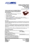
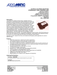
HYDRAULIC VALVE CONTROLLER – 24 I/O
5 Analog and 6 Digital Inputs
1 Temperature Sensor and 1 RPM Sensor Interface
2 PWM Inputs
6 Proportional and 4 ON/OFF Current Outputs
RS232 and CAN ports
P/N: AX020700 SERIES
Description:
The hydraulic I/O controller provides precise,
repeatable control of 6 proportional and 4 on/off
solenoid valves (or other combination). Valve current
control is based on 1 temperature sensor input, 1 RPM
sensor input, up to 2 PWM inputs, up to 5 universal
analog inputs (0-5V, 0-10V, 0-20mA or 4-20mA) and/or
up to 6 digital inputs. Two +5V references are available
to power the analog input devices. The robust design
accepts 9…32V power supply input and is packaged in
an IP67 rated housing with 48-pin connectors. The
controller is designed for remote mounting. RS-232
port interfaces to PC with Tera Term freeware for user
configuration and diagnostics. Optional CAN
communications permit networking.
Many hydraulic control applications in harsh environments can be accommodated with this hardware and
application-specific software.
Ordering Part Number:
AX020700 Series
OEM versions with application-specific software are available on request.
Technical Specifications:
The specifications represent a particular hardware platform. Application-specific software is provided.
Input Specifications
Power Supply Input - Nominal
12 or 24VDC nominal; 9…32 VDC power supply range
Reverse Polarity Protection
Provided
Analog Inputs
Temperature Sensor Input
Sensor Ground
Analog Inputs
Analog Ground
1 thermistor input (100 Ohm to 100 Kohm)
User specifies sensor, range of temperature control and setpoints
Temperature sensor ground connection is provided.
5 analog inputs available
0-5V, 0-10 VDC, 4-20 mA, 0-20 mA
Four analog ground connections are provided.
Frequency Inputs
PWM Pulse Input
PWM Ground
Active Sensor
Passive Sensor
2 PWM pulse – low/high pulse up to 10 kHz
Adjustable from 0-100% Duty Cycle (5-95% default)
For example, the controller could interface to an active sensor (hall effect) for pulse
input (Engine RPM) or to a PWM signal from an engine ECM.
A PWM ground is provided.
nd
Using the 2 PWM input pin, the controller can interface with an active sensor.
Power is provided to the sensor from one of the +5V reference voltages.
The controller can interface with a passive sensor (inductive pick up)
such as a magnetic speed sensor.
Digital Inputs
Digital Inputs
Digital Ground
6 digital inputs available
(Active Low or Active High is software selectable)
A digital ground connection is provided.
Output Specifications
Maximum Current Output
(High frequency PWM output)
Digital Output
Reference Voltage
Output Current Adjustments
Superimposed Dither
Ramp Rate
Six independent outputs (up to 2A) for proportional valves
Specify outputs required upon ordering (factory programmed).
Overcurrent protection is provided
Short circuit protection is provided.
Four outputs (2A max.) for ON/OFF valves
Two +5V, 50 mA (Protected against GND and Power Supply connections)
One +5V for Analog Input 1
I-max. (specified by user – set in software)
I-min. (specified by user – set in software)
All current settings are adjustable from 0 to 2 Amps.
Dither Amplitude:
10% I-max. (fixed)
Dither Frequency:
200 Hz (factory default); Adjustable from 70-350 Hz
Ramps (specified by user – set in software)
Adjustable from 0-5 seconds.
General Specifications
Microprocessor
Control Logic
CAN Interface
Interface
Electrical Connections
Packaging and Dimensions
Operating Conditions
Vibration
Protection
DSP56F8346
Application – specific software provided
1 CAN port
Bosch Controller Area Network Specification (CAN 2.0B)
Software support for SAE J1939 stack (on request)
CANopen and other higher level protocols on request.
RS-232 port for setpoint configuration, software upgrade and diagnostics.
RS232 serial communication interfaces to a serial port (i.e. COM1) on a PC
(115200 Baud Rate, N81, Xon/Xoff Flow Control)
TM
Tera Term or Microsoft HyperTerminal or an equivalent data terminal
48 pin
Cinch ModICE receptacle (p/n: 581 01 48 005)
Mating plug: SHS (p/n: 581 01 18 023)
Mating plugs are provided with prototypes only.
Use dielectric grease on the pins when installing the controller.
High Temperature Nylon housing
Cinch ModICE small enclosure (p/n: 581 01 30 04X)
6.03 x 5.30 x 1.85 inches 153.20 x 134.60 x 47.00 mm
(W x L x H excluding mating plug)
-40 to 85°C (-40 to 185°F)
Vibration compliance is suitable for mobile equipment applications.
IP67; Unit is conformally coated within the housing. Plugs carry an IP69 rating.
2
Connections (Typical):
Pin #
31
32
33
34
35
36
37
38
39
40
41
42
43
44
45
46
47
48
18-pin Connector
Function
Proportional Solenoid 1+
Proportional Solenoid 2+
Proportional Solenoid 3+
Proportional Solenoid 4+
Proportional Solenoid 5+
Proportional Solenoid 6+
Power_GND
Power_GND
Power_GND
Power_GND
Power_GND
Power_GND
Battery +
Battery -/Power_GND
ON/OFF Output 1
ON/OFF Output 2
ON/OFF Output 3
ON/OFF Output 4
Refer to installation instructions for a specific part number for actual pin out.
Pin #
1
2
3
4
5
6
7
8
9
10
11
12
13
14
15
16
17
18
19
20
21
22
23
24
25
26
27
28
29
30
30-pin Connector
Function
CAN High (on request)
Digital Input 1
Digital Input 2
Digital Input 3
Digital Input 4
+5V Reference (Protected)
+5V Reference (Protected)
Analog Input 2
Analog Input 3
+5V Reference for Analog Input 1
CAN Low (on request)
Digital Input 5
Digital Input 6
Temperature Sensor Input
Passive Sensor Input (Inductive Pickup Sensor)
PWM Input 1
PWM Input 2 (Active Sensor)
Analog Input 4
Analog Input 5
Analog Input 1
RS-232 Transmit (DB-9 Female, pin 2)
RS-232 Receive (DB-9 Female, pin 3)
RS-232 GND (DB-9 Female, pin 5)
Analog GND (Temperature Sensor GND)
Analog GND (Passive Sensor GND)
Analog_GND
Analog_GND
Analog_GND
Analog_GND
Analog Input 1_GND
3
CAN communications:
Contact the manufacturer for details.
RS-232 communications:
For further details refer to the user manual for the specific part number.
Using a PC and Tera term freeware, the user can select between displaying system parameters,
changing system parameters, setting the default values, loading new software and showing the
internal state of the controller (diagnostics).
NB. Tera term is freeware and is downloadable from
http://hp.vector.co.jp/authors/VA002416/teraterm.html.
1. Setting Up PC Communications to the Controller
•
•
•
•
Connect an RS-232 to DB-9 cable adaptor to the controller and a PC.
Use a stable power supply. With the power supply OFF, connect the controller Power- to
the power supply Ground, and the Power+ to the power supply +.
Open Tera Term Pro, and set it up.
(Free downloadable from http://hp.vector.co.jp/authors/VA002416/teraterm.html)
Select Serial with the appropriate COM port.
4
•
Go to Setup/Serial Port and change the settings exactly as shown below.
•
•
Go to Setup/Terminal and verify that New-line Transmit and Receive are CR.
Adjust the window size as desired by checking ‘Term size = win size’.
2. Configuring the Controller - Main Menu
•
•
To access the main menu for existing software, turn ON power to the controller.
Follow the prompts on the screen to view or to change the configurable parameters.
For further details on configuration, refer to the user manual provided with a specific controller part
number.
Form: TDAX020700-01/09/06
5