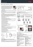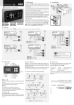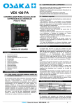
1
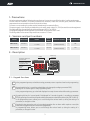
1454H502 Ed.01
GB
AKO-14545
AKO-14545-C
5-stage compressor racks +
2 converter outputs
User Manual
1454H502 Ed.01
Contents
Page
1.- Precautions ......................................................................................................................................3
2.- Versions and part numbers ...............................................................................................................3
3.- Description.......................................................................................................................................3
3.1.- Keypad functions.................................................................................................................3
3.2.- Display messages ................................................................................................................4
4.- Inicio rápido.....................................................................................................................................5
4.1.- “WIZARD” table description................................................................................................5
4.2.- Legend ...............................................................................................................................6
4.3.- “WIZARD” table .................................................................................................................7
5.- Wiring..............................................................................................................................................9
6.- Location of the probes....................................................................................................................10
6.1.- Proportional mode ............................................................................................................10
6.2.- Neutral zone mode............................................................................................................11
6.3.- Pump Down......................................................................................................................12
7.- Fan control.....................................................................................................................................13
7.1.- Proportional mode ............................................................................................................13
7.2.- Neutral zone mode............................................................................................................14
7.3.- Floating condensation .......................................................................................................15
7.4.- Alarms ..............................................................................................................................15
7.5.- Remote disconnection .......................................................................................................17
8.- Connectivity ...................................................................................................................................17
9.- Parameter setup .............................................................................................................................18
9.1.- Programming Menu ..........................................................................................................18
9.2.- Parameters........................................................................................................................19
9.3.- Limits and default values of the pressure and temperature parameters according to units.. .24
10.- Technical specifications ................................................................................................................25
10.1.- Dimensions .....................................................................................................................26
10.2.- Mounting........................................................................................................................26
AKO Electromecánica thanks and congratulates you for purchasing our product, in whose development and manufacture the most
innovative technology has been used, as well as strict production and quality control processes.
Our commitment to satisfy our customers and our continuous efforts to improve every day can be seen in the various quality certifications we have obtained.
This is a high performance, high technology product. The operation and final performance of the equipment depend on proper planning, installation, configuration and commissioning. Read this manual carefully before installation, and always follow its instructions.
Only qualified personnel should install or perform technical assistance on this product.
This product is designed to be used in the applications described in the product manual. AKO Electromecánica gives no guarantee
of its operation in any use not foreseen in the manual, and is not responsible for any damage resulting from improper use, configuration, installation or commissioning.
It is the responsibility of the installer and the customer to comply with and ensure others comply with all regulations applicable to
installations incorporating our products. AKO Electromecánica is not responsible for any damage caused by non-compliance with regulations. Follow strictly the instructions given in this manual.
To maximise the service life of our equipment, these recommendations should be followed:
Do not expose electronic equipment to dust, dirt, water, rain, humidity, high temperatures, chemicals or corrosive substances of any sort.
Do not submit the equipment to blows or vibrations nor try to manipulate it differently from shown in the manual.
Never exceed the specifications and limitations indicated in the manual.
Always respect the specified ambient working and storage conditions.
During and after installation, avoid leaving loose, broken, unprotected or damaged wiring, since they might constitute a risk for the equipment and its users.
AKO Electromecánica reserves the right to make any non-metrology modification to the documentation or the equipment without
previous notice.
2
1454H502 Ed.01
1- Precautions
-Using the equipment without following the manufacturer's instructions may affect the device's safety requirements.
-The unit must be installed in a location protected from vibrations, water and corrosive gases, where the ambient
temperature does not exceed that shown in the technical data.
-To ensure a correct reading, the probe must be located away from external effects.
-The power supply circuit must be provided with a main switch rated at least 2 A, 230 V, located close to the equipment.
The cables will enter through the back and should be type H05VV-F or H05V-K.
-The gauge will depend on local regulations, but should in no case be less than 1 mm².
-The wiring cables for the contact relays must have a section of 2.5 mm2.
2.- Versions and part numbers
POWER SUPPLY
PROBES
DIGITAL
INPUTS
ANALOGUE OUTPUTS
AKO-14545
90-240 V
2 x 0-5 V / 4-20 mA / NTC
+ 1 x NTC
Up to 6
2 x 0-10 V / 4-20 mA
(inverter controls)
5
NO
AKO-14545-C
90-240 V
2 x 0-5 V / 4-20 mA / NTC
+ 1 x NTC
Up to 6
2 x 0-10 V / 4-20 mA
(inverter controls)
5
YES
MODELS
RELAYS COMMUNICATION
3.- Description
Active relay
indicators
Display
The display shows the
pressure value
The display shows the
temperature value
R1
R2
R3
R4
R5
PRES
TEMP
Program
Mode
Active alarm
ESC
SET
Keyboard
3.1.- Keypad functions
ESC
SET
In the programming menu, exit without saving parameter, return to previous level or exit programming.
By pressing this key for 1 second the probe display units change (according to parameter C09).
Pressing for 10 seconds goes to the programming menu.
In the programming menu, go to the level displayed or accept the new value while setting a parameter.
By pressing this key for 1 second probe 2 is displayed for 5 seconds (or probe 1, according to parameter
P02). By pressing a second time the probe ambient temperature value will be shown (only if I07 or I08=3).
In the programming menu, allows you to scroll through the various levels or, during the setting of a
parameter, to change the value.
Pressing this key returns the unit to its standard operation after an alarm which requires a reset (the
causes which triggered the alarm must have disappeared).
In programming menu, allows you to scroll through the various levels or, during the setting of a
parameter, to change the value.
3
1454H502 Ed.01
3.2.- Display messages
PRES
TEMP
Flashing 0: Access code (Password) request
You must enter the access code configured on L5 to execute the requested
function (P. 23).
R1
R2
R3
R4
R5
PRES
TEMP
PRES
TEMP
Probe 1, 2 or 3 faulty
(open circuit, crossover or temperature outside the probe limits; NTC: -50
To 99 ºC; PTC: -50 To 150 ºC). (Activates alarm relay)
PRES
TEMP
PRES
TEMP
Clock battery discharged or clock deprogrammed
(Activates alarm relay) (P. 16)
PRES
TEMP
Low pressure alarm due to probe 1
(Activates alarm relay) (P. 16)
PRES
TEMP
High pressure alarm due to probe 2
(Activates alarm relay) (P. 16)
R1
R2
R3
R4
R5
PRES
TEMP
PRES
TEMP
PRES
TEMP
PRES
TEMP
PRES
TEMP
PRES
TEMP
PRES
TEMP
R1
R2
R3
R4
R5
Thermal alarm inputs 1 to 5
(Activates alarm relay and stops the output associated to the relevant
thermal) (P. 16)
Severe external alarm activated due to digital input I5 or I6
(According to parameters I07 and I08) (Activates alarm relay and stops
compressors and fans) (P. 16)
Low pressure alarm due to digital input I5 or I6
(According to parameters I07 and I08) (Activates alarm relay and stops
compressors and fans) (P. 15)
High pressure alarm due to digital input I5 or I6
(According to parameters I07 and I08) (Activates alarm relay, stops
compressors and activates fans) (P. 15)
Regulation remotely stopped due to digital input I5 or I6; all
stages/compressors are disconnected. (According to parameters I07 and
I08) (Does not activate alarm relay) (P. 17)
Pump down detained due to time (According to parameter E09)
(Does not activate alarm relay) (P. 16)
4
1454H502 Ed.01
4- Inicio rápido
The unit has a wizard that configures the unit's parameters and assigns the input and output functions
according to the installation type chosen.
When connecting the power supply for the first time, the Configuration Wizard will start, displaying the message
INI on screen. Follow the 4 steps detailed below and the unit will be ready to operate:
By using keys N and Q, select the most suitable option according to the installation type in
PRES
accordance with the "WIZARD" table on page 7 and press SET. The wizard configures the
TEMP
equipment parameters and assigns the input and output functions according to the
installation type chosen.
1
2
3
4
PRES
TEMP
PRES
TEMP
PRES
TEMP
Select the refrigerant gas type used from amongst the following options:
0=R134a 1=R404a 2=R717a 3=R22
4=R410a 5=R507a 6=R744
7=R407a 8=R407f 9=R1234y 10=R448a 11=R449a 12=R450a
Select the primary and secondary display units from amongst the following options:
0=bar-ºC; 1=psi-ºF; 2=psi-ºC; 3=bar-ºF; 4=ºC-bar;
5=ºF-psi; 6=ºC-psi; 7=ºF-bar
Configure the rest of the parameters to their default value? :
0=No, the configuration is kept for all the parameters except for C01, C02, C04, C05 C06, C08
and C09.
1=Yes, all the parameters are configured to their default value (see parameters table)
(This option does not affect parameters C01, C02, C04, C05 C06, C08 and C09)
In order to start the wizard again, disconnect the unit's power supply, reconnect it and, during the subsequent
8 seconds, press the key sequence N, Q, SET.
4.1.- “WIZARD” table description
The “WIZARD” annex table is divided into 3 groups of columns.
The first group describes the different types of installation (no. of compressors and fans, whether they have a
converter, etc.) associated to their INI option.
Installation
Compressors with
inverter
Fans without
inverter
Stages by compressor
Compressors without
inverter
1
INI
1
2
3
4
1
1
1
1
2
1
2
3
4
- with inverter
Fans
5
-
1454H502 Ed.01
The second group specifies the function assigned to each relay depending on the INI option selected.
Relays
Relays R1 to R5
OUTPUTS
R1
R2
R3
R4
R5
CV
CV
CV
CV
C2
C2
C2
C2
C2a
C2a
C3
C2a
FV
C2b
FV
C2b
AL
FV
AL
FV
Function assigned to each relay
depending on the INI option selected*
The third group specifies the function assigned to each digital input depending on the INI option selected.
Inputs
Inputs I1 to I6
OUTPUTS
R5
I1
I2
AL
FV
AL
FV
T-VAR-C1
T-VAR-C1
T-VAR-C1
T-VAR-C1
T-C2
T-C2
T-C2
T-C2
INPUTS
I3
I4
T-VAR-F
T-VAR-F
T-C3
T-VAR-F
T-VAR-F
-
I5
I6
L.P.
L.P.
L.P.
L.P.
H.P.
H.P.
H.P.
H.P.
Function assigned to each input
depending on the INI option selected*
4.2.- Legend
Compressors without inverter
Fans without inverter
CV:
FV:
Cx:
1
2
Number of stages per compressor
Compressor with inverter
Fans with inverter
FUNCTION OF THE OUTPUTS
Cxa, Cxb,
Output stages 1, 2 and 3 of compressor x
RUN inverter output (compressor)
Cxc:
Output fan without inverter
RUN inverter output (fans)
Vx:
Alarm output
Output compressors without inverter
AL:
FUNCTION OF THE INPUTS
Thermal input frequency inverter
Thermal input fan
T-Vx:
T-VAR-C1:
(compressor)
Input high pressure switch
T-VAR-F: Thermal input frequency inverter (fans)
H.P.:
Input low pressure switch
Thermal input compressor
L.P.:
T-Cx:
x: Compressor or fan no.
a, b, c: Compressor stages
6
1454H502 Ed.01
4.3.- “WIZARD” table
INI
1
OUTPUTS
R1 R2 R3 R4 R5
2
1
2
3
4
5
6
7
8
9
1
1
1
1
2
2
3
4
5
1
2
3
4
1
2
1
1
1
-
-
-
C1
C1
C1
C1
C1
C1
C1
C1
C1
C1a C1a C1b C1a C1b C1c
C2
C1a C2 C2a
C2 C3
C2 C3 C4
C2 C3 C4
10
11
12
13
14
15
16
17
18
0
1
1
1
1
2
2
3
4
1
2
3
4
1
2
1
1
1
1
1
1
1
1
1
1
1
-
-
CV
CV
CV
CV
CV
CV
CV
CV
CV
C2
C2
C2
C2
C2
C2
C2
C2
19
-
-
-
-
FV
-
20
21
22
23
24
25
26
27
1
1
1
1
2
2
3
4
1
2
3
4
1
2
1
1
-
-
C1
C1
C1
C1
C1
C1
C1
C1
28
29
30
31
32
33
0
1
1
1
2
3
1
2
3
1
1
1
1
1
1
1
1
-
CV
CV
CV
CV
CV
CV
AL
AL
AL
AL
AL
AL
AL
AL
C5
I2
T-C1
T-C1
T-C1
T-C1
T-C1
T-C1
T-C1
T-C1
T-C1
T-C2
T-C2
T-C2
T-C2
T-C2
T-C3
T-C3
T-C3
T-C2
T-C2
T-C2
T-C2
T-C2
T-C2
T-C2
T-C2
-
AL T-VAR-C1
AL T-VAR-C1
C2a AL T-VAR-C1
C2a C2b AL T-VAR-C1
C2a C2b C2c T-VAR-C1
C3
AL T-VAR-C1
C2a C3 C3a T-VAR-C1
C3 C4 AL T-VAR-C1
C3 C4 C5 T-VAR-C1
-
-
AL
T-VAR-F
FV
C1a FV
C1a C1b FV
C1a C1b C1c
C2 FV
C1a C2 C2a
C2 C3 FV
C2 C3 C4
AL
AL
AL
FV
AL
FV
AL
FV
T-C1
T-C1
T-C1
T-C1
T-C1
T-C1
T-C1
T-C1
FV
C2
C2
C2
C2
C2
AL
AL
AL
FV
AL
FV
FV
C2a FV
C2a C2b
C3 FV
C3 C4
7
INPUTS
I3
I4
I1
I5
I6
T-C4
T-C4
L.P.
L.P.
L.P.
L.P.
L.P.
L.P.
L.P.
L.P.
T-C5
H.P.
H.P.
H.P.
H.P.
H.P.
H.P.
H.P.
H.P.
H.P.
T-C3
T-C3
T-C3
T-C3
T-C4
T-C4
L.P.
L.P.
L.P.
L.P.
L.P.
L.P.
L.P.
L.P.
T-C5
H.P.
H.P.
H.P.
H.P.
H.P.
H.P.
H.P.
H.P.
H.P.
-
-
L.P.
H.P.
T-VAR-F
L.P.
T-VAR-F
L.P.
T-VAR-F
L.P.
T-VAR-F
L.P.
T-C2 T-VAR-F
L.P.
T-C2 T-VAR-F
L.P.
T-C2
T-C3 T-VAR-F L.P.
T-C2
T-C3
T-C4 T-VAR-F
H.P.
H.P.
H.P.
H.P.
H.P.
H.P.
H.P.
H.P.
T-VAR-C1 T-VAR-F
L.P.
T-VAR-C1 T-C2 T-VAR-F
L.P.
T-VAR-C1 T-C2 T-VAR-F
L.P.
T-VAR-C1 T-C2 T-VAR-F
L.P.
T-VAR-C1 T-C2
T-C3 T-VAR-F L.P.
T-VAR-C1 T-C2
T-C3
T-C4 T-VAR-F
H.P.
H.P.
H.P.
H.P.
H.P.
H.P.
1454H502 Ed.01
INI
1
INPUTS
R1 R2 R3 R4 R5
2
I1
I2
OUTPUTS
I3
I4
I5
I6
34
35
36
37
38
-
-
-
1
2
3
4
5
-
V1
V1
V1
V1
V1
V2
V2
V2
V2
V4
V4
AL
AL
AL
AL
V5
T-V1
T-V1
T-V1
T-V1
T-V1
T-V2
T-V2
T-V2
T-V2
T-V3
T-V3
T-V3
T-V4
T-V4
L.P.
L.P.
L.P.
L.P.
T-V5
H.P.
H.P.
H.P.
H.P.
H.P.
39
40
41
42
43
44
45
46
47
48
49
50
51
52
53
54
55
1
1
1
1
1
1
1
1
1
1
2
2
2
2
3
3
4
1
1
1
1
2
2
2
3
3
4
1
1
1
2
1
1
1
-
1
2
3
4
1
2
3
1
2
1
1
2
3
1
1
2
1
-
C1
C1
C1
C1
C1
C1
C1
C1
C1
C1
C1
C1
C1
C1
C1
C1
C1
V1
V1 V2
V1 V2 V3
V1 V2 V3
C1a V1
C1a V1 V2
C1a V1 V2
C1a C1b V1
C1a C1b V1
C1a C1b C1c
C2 V1
C2 V1 V2
C2 V1 V2
C1a C2 C2a
C2 C3 V1
C2 C3 V1
C2 C3 C4
AL
AL
AL
V4
AL
AL
V3
AL
V2
V1
AL
AL
V3
V1
AL
V2
V1
T-C1
T-C1
T-C1
T-C1
T-C1
T-C1
T-C1
T-C1
T-C1
T-C1
T-C1
T-C1
T-C1
T-C1
T-C1
T-C1
T-C1
T-V1
T-V1
T-V1
T-V1
T-V1
T-V1
T-V1
T-V1
T-V1
T-V1
T-C2
T-C2
T-C2
T-C2
T-C2
T-C2
T-C2
T-V2
T-V2
T-V2
T-V2
T-V2
T-V2
T-V1
T-V1
T-V1
T-V1
T-C3
T-C3
T-C3
T-V3
T-V3
T-V3
T-V2
T-V2
T-V1
T-V1
T-C4
L.P.
L.P.
L.P.
T-V4
L.P.
L.P.
L.P.
L.P.
L.P.
L.P.
L.P.
L.P.
T-V3
L.P.
L.P.
T-V2
T-V1
H.P.
H.P.
H.P.
H.P.
H.P.
H.P.
H.P.
H.P.
H.P.
H.P.
H.P.
H.P.
H.P.
H.P.
H.P.
H.P.
H.P.
56
57
58
59
60
61
62
63
64
65
66
67
68
0
0
0
0
1
1
1
1
1
1
2
2
3
1
1
1
2
2
3
1
1
1
1
1
1
1
1
1
1
1
1
1
1
1
1
1
2
3
4
1
2
3
1
2
1
1
2
1
-
CV
CV
CV
CV
CV
CV
CV
CV
CV
CV
CV
CV
CV
V1
V1
V1
V1
C2
C2
C2
C2
C2
C2
C2
C2
C2
AL
AL
AL
V4
AL
AL
V3
AL
V2
V1
AL
V2
V1
T-VAR-C1
T-VAR-C1
T-VAR-C1
T-VAR-C1
T-VAR-C1
T-VAR-C1
T-VAR-C1
T-VAR-C1
T-VAR-C1
T-VAR-C1
T-VAR-C1
T-VAR-C1
T-VAR-C1
T-V1
T-V1
T-V1
T-V1
T-C2
T-C2
T-C2
T-C2
T-C2
T-C2
T-C2
T-C2
T-C2
T-V2
T-V2
T-V2
T-V1
T-V1
T-V1
T-V1
T-V1
T-V1
T-C3
T-C3
T-C3
T-V3
T-V3
T-V2
T-V2
T-V2
T-V1
T-V1
T-C4
L.P.
L.P.
L.P.
T-V4
L.P.
L.P.
T-V3
L.P.
L.P.
L.P.
L.P.
T-V2
T-V1
H.P.
H.P.
H.P.
H.P.
H.P.
H.P.
H.P.
H.P.
H.P.
H.P.
H.P.
H.P.
H.P.
L.P.
H.P.
V3
V3
V3
V2
V2 V3
V2 V3
V1
V1 V2
V1 V2
C2a V1
C2a V1
C2a C2b
C3 V1
C3 V1
C3 C4
In the case of floating condensation (F08=1), the highlighted inputs are configured as inputs for the
ambient temperature probe.
8
1454H502 Ed.01
5.- Wiring
The function of each relay output or digital input depends on the option chosen in the INI wizard (See page 5).
I max.:
16 A
L N
S1
0-10 V (³ 5KW) /
4-20 mA (£ 500W)
(C10)
S3 (F08=1)
8
9
10 11
GND
+5 V
+15 V
IN 1
S1
S2
S2
+
19 20
GND
7
I
+5 V
6
I
14 15 16 17 18
+15 V
5
19 20
IN 1
4
+5 V
3
I
+15 V
2
I
14 15 16 17 18
IN 1
1
4-20 mA
IN 2
90-240 V~
50/60 Hz
19 20
IN 2
R5
R1
R2
R3
R4
+
GND
+
19 20 21 22 23 24 25 26 27 28
S1
Tr+
TrGnd
I1
I2
I3
I4
I5
I6
Modbus*
IN 2
14 15 16 17 18
GND
S3 (F08=1)
12 13 14 15 16 17 18
AKO-14545
AKO-14545-C
S2
NTC
0-5 V
+5 V
+15 V
14 15 16 17 18
IN 1
+5 V
+15 V
IN 1
19 20
+
S2
+ V
19 20
GND
+
14 15 16 17 18
Control of compressor inverter
S1: Aspiration probe
S1
V
S2
IN 2
+
V
GND
R5
IN 2
R1 R3
R2 R4
S1 V
+ -
Control of fan inverter
S2: Discharge probe
Probes S1 and S2 must be the same type (NTC, 4-20 mA or 0-5 V). They will be active depending on the INI value
selected.
Location of the probes
S3
S2
S1
9
1454H502 Ed.01
6.- Location of the probes
6.1.- Proportional mode
WITHOUT FREQUENCY CONVERTER
The controller activates (red line) or deactivates (green line) the different stages/compressors available in a linear
manner depending on the reading obtained in probe 1 until the Set Point (E01) is reached again, as shown in
the following figure.
Direct
operation (C07=0)
E01
Inverse
E01
operation (C07=1)
stage / compressor 4 ON
Stages /
Compressors
stage / compressor 3 ON
stage / compressor 2 ON
stage / compressor 1 ON
E06
n
Pressure in Probe 1
E06
n
Bandwidth (E06)
Bandwidth (E06)
n: Number of stages/compressors available
WITH FREQUENCY CONVERTER
If there is a frequency converter, the frequency converter modulates the power of compressor 1 between 0 and
100% (blue zone). If demand increases, the following compressor or stage (without converter) is added, again
modulating the power of compressor 1 using the converter, and so on.
This method allows modulating the total power available using just one frequency converter.
Direct
operation (C07=0)
E01
Inverse
operation (C07=1)
100%
Total power applied
100%
0%
0%
100%
100%
R4
R4
R3
R3
R3
R3
R2
R2
R2
R2
0%
0%
100%
100%
0%
E01
0%
100%
100%
R2
0%
R2
E06
n
0%
E06
n
Bandwidth (E06)
Bandwidth (E06)
n: Number of stages/compressors available
In both cases, the delays t01 to t04 must be accounted for.
10
Pressure in Probe 1
1454H502 Ed.01
6.2.- Neutral zone mode
WITHOUT FREQUENCY CONVERTER
In this mode, a neutral zone is defined, whose lower limit is the Set Point minus the bandwidth, and whose upper
limit is the Set Point plus the bandwidth. While the reading of probe 1 remains in that zone, no stages or
compressors are connected or disconnected.
Upper limit
SP+E06
NEUTRAL ZONE
SP
Lower limit
SP-E06
If the upper limit is exceeded, the controller activates the different stages/compressors separated by the interval
defined in parameter t03 (red line) until returning to the neutral zone.
If the lower limit is exceeded, the controller deactivates the different stages/compressors separated by the interval
defined in parameter t04 (green line) until returning to the neutral zone.
E01
Direct
operation (C07=0)
t04
t04
E01
Inverse
operation (C07=1)
stage / compressor 4 ON
Stages /
Compressors
stage / compressor 3 ON
stage / compressor 2 ON
stage / compressor 1 ON
t03
t03
Pressure in Probe 1
In order to deactivate a stage/compressor, the interval t01 must have passed, and interval t02 defines the
minimum interval between starts of the same stage/compressor.
11
1454H502 Ed.01
WITH FREQUENCY CONVERTER
Operation is the same as in the previous point, but modulating the power of compressor 1 with the converter
while it remains in the neutral zone using a PID control.
Near the upper limit, the compressor operates at its maximum capacity, and if said limit is exceeded, more
stages/compressors are added, in accordance with the interval defined in t02, until returning to the neutral zone.
Near the lower limit, the compressor operates at its minimum capacity, and if said limit is exceeded, it stops. The
rest of the stages/compressors will stop, in accordance with the interval programmed in t01, until re-entering the
neutral zone, upon which compressor 1 activates again at its minimum capacity.
Pres / Temp (Probe 1)
t02
R4
R3
R3
R2
R2
R2
R1
R1
R1
Upper limit
SP+E06
SP
R1
Converter status:
100 %
NEUTRAL
ZONE
Lower limit
SP-E06
R4
R3
R3
R2
100 %
0%
R2
OFF
(R1 OFF)
R2
t01
Time
Example with the type of compressor rotation configured as sequential (E04=1)
6.3.- Pump Down
It is only available if the type of operation is direct (C07=0).
When the pressure reaches the Set Point value (E01) in probe 1, the last stage/compressor remaining in operation
does not stop; it continues to reduce the pressure until reaching the value configured in parameter E08.
In the event of a failure, if the value of E08 is not reached, the controller will stop the compressor once the security
interval defined in E09 has passed, displaying the message “PdA” (an informative message that does not affect
the unit's operation).
For this function to be active, the parameter E08 must be configured below the Set Point (E01).
12
1454H502 Ed.01
7.- Fan control
7.1.- Proportional mode
WITHOUT FREQUENCY CONVERTER
The controller activates (red line) or deactivates (green line) the different fans available in a linear manner
depending on the reading obtained in probe 2 until the Set Point (E01) is reached again, as shown in the
following figure.
The delays t05 to t08 must be accounted for.
F01 Direct
operation (C07=0)
Inverse
operation (C07=1)
F01
Fan 4 ON
Fans active
Fan 3 ON
Fan 2 ON
Fan 1 ON
F06
4
F06
4
Bandwidth (F06)
Pressure in Probe 2
Bandwidth (F06)
WITH FREQUENCY CONVERTER
If there is a frequency converter, the frequency converter modulates the power of the fans between 0 and 100%.
F01 Direct
operation (C07=0)
Inverse
operation (C07=1)
F01
Fan power
Fans at 100%
Fans at 0%
Bandwidth (F06)
Bandwidth (F06)
13
Pressure in Probe 2
1454H502 Ed.01
7.2.- Neutral zone mode
WITHOUT FREQUENCY CONVERTER
In this mode, a neutral zone is defined, whose lower limit is the Set Point minus the bandwidth, and whose upper
limit is the Set Point plus the bandwidth. While the reading of probe 2 remains in that zone, no fans are connected
or disconnected.
Upper limit
SP+F06
SP
NEUTRAL ZONE
Lower limit
SP-F06
If the upper limit is exceeded, the controller activates the different fans separated by the interval defined in
parameter t07 (red line) until returning to the neutral zone.
If the lower limit is exceeded, the controller deactivates the different fans separated by the interval defined in
parameter t08 (green line) until returning to the neutral zone.
F01
Direct
operation (C07=0)
t08
t08
Inverse
operation (C07=1)
F01
Fan 4 ON
Fans
Fan 3 ON
Fan 2 ON
Fan 1 ON
t07
t07
Pressure in Probe 2
In order to deactivate a fan, the interval t05 must have passed, and interval t06 defines the minimum interval
between starts of the same stage/compressor.
14
1454H502 Ed.01
WITH FREQUENCY CONVERTER
Operation is the same as in the previous point, but modulating the power of the fans with the converter while it remains
in the neutral zone using a PID control.
Near the upper limit, the fans operate at their maximum capacity, and if said limit is exceeded, the capacity is kept at its
maximum until returning to the neutral zone.
Near the lower limit, the fans operate at their minimum capacity, and if said limit is exceeded, they stop until returning
to the neutral zone, upon which they activate again at their minimum capacity.
Pres / Temp (Probe 2)
100 %
SP
Converter status
Upper limit
SP+E06
NEUTRAL
ZONE
Upper limit
SP-E06
100 %
0%
OFF
(R1 OFF)
Time
7.3.- Floating condensation
The controller modulates the evaporation Set Point taking into account the ambient temperature (requiring
connecting probe 3) and the power of the compressors.
This type of control improves the COP (the relationship between cooling power and consumed electrical energy)
and hence increases the energy performance of the installation.
This mode is only valid if the fans of the condenser are controlled, with or without a frequency converter.
7.4- Alarms
IMPORTANT: The alarms that cause compressors and fans to stop will do so in a sequential manner,
with a delay of 5 seconds between stops.
LOW AND HIGH PRESSURE ALARM DUE TO DIGITAL INPUT
When the digital input I5 or I6 is activated, the message HPA (High) or LPA (Low) is shown on TEMP
screen, the alarm relay is activated (if available) and the compressors are stopped.
If the alarm is due to low pressure, the fans stop; if it is due to high pressure, the fans activate
regardless of parameter F07.
If the cause that triggered the alarm disappears, the installation returns to its standard operation.
TEMP
Parameter A09 defines the number of high-pressure alarms allowed per hour. If this value is
exceeded, the unit must be manually reset by pressing the Q key in order for it to return to its
standard operation, once the cause that triggered the alarm has disappeared.
This requires the parameters I07 or I08 to be set to 0 or 1.
When the readings return to their normal values, the alarm relay deactivates but the R indicator remains on until
the Q key is pressed.
PRES
PRES
15
1454H502 Ed.01
LOW AND HIGH PRESSURE ALARM DUE TO PROBES 1 AND 2
TEMP
If the reading in probe 1 reaches the value set for parameter A03, the message ALL (Low
pressure) is displayed on screen and the alarm relay activates (if available).
This alarm differential is established in parameter A04.
If the reading in probe 1 reaches the value set for parameter A05, the message ALH (High TEMP
pressure) is displayed on screen and the alarm relay activates (if available).
This alarm differential is established in parameter A06.
When the readings return to their normal values, the alarm relay deactivates but the R indicator remains on until
the Q key is pressed.
PRES
PRES
PROTECTION ALARMS
PRES
TEMP
If one of the thermal protections goes off (digital inputs I1 to I5, according to the configuration),
the message At1 ... is displayed on screen At5, the associated element (compressor or fan) stops
and the alarm relay activates (if available).
Once the protection is reset, the installation returns to its standard operation, but the alarm relay remains activated
until the Q key is pressed.
SEVERE EXTERNAL ALARM
When the digital input configured as a severe external alarm (I07 or I08=4) is activated, the
screen displays the message AES, the compressors and fans stop and the alarm relay activates.
Once the cause that triggered the alarm disappears, the installation returns to its standard
operation, but the R indicator remains activated until the Q key is pressed.
PRES
TEMP
PROBE 1, 2 or 3 ERROR
PRES
TEMP
If an error occurs in probes 1, 2 or 3 (disconnection, cross-over or probe out of range), the
screen displays the messages E1, E2 or E3 respectively, the alarm relay activates and the
compressors and fans go on to operate according to parameters A01 and A02.
Once the cause that triggered the alarm disappears, the installation returns to its standard operation, but the R
indicator remains activated until the Q key is pressed.
DEPROGRAMMED CLOCK ALARM
If the unit remains without electrical supply for a period longer than 6 hours, or upon its first startup, the screen displays the message Ar, indicating that the internal clock is deprogrammed. The
unit will continue its standard operation, but if the energy save mode has been activated, it will
not start. In order to set the date and time again, adjust parameters r01 to r05. Activates the
alarm relay.
PUMP DOWN ALARM STOPPED DUE TO TIME
PRES
TEMP
PRES
TEMP
If, during pump down, the maximum interval configured in E09 passes before the stop value
specified by E08 is reached, the last stage will stop and the message PdA will be displayed. Does
not activate the alarm relay.
16
1454H502 Ed.01
Alarm delay
These delays prevent the display of specific alarms while allowing the unit to recover normal operation after certain
events.
-Delays in start-up (A08): Delays the activation of the alarms upon receiving power supply (start-up or after a
fault in the power supply). This allows starting up the installation avoiding constant alarm statuses.
-Alarm delay (A07): It delays the activation of the high and low pressure alarms (A03 and A05) from the time
that the programmed values are reached.
-Turn-on delay time of alarms due to digital input 5 (I09): It delays the activation of activated alarms due to
digital input 5. The type of alarm to be activated depends on the configuration of parameter I07. It does not take
effect if parameter I07 is set to 2 (Thermal alarm).
-Turn-on delay time of alarms due to digital input 6 (I10): It delays the activation of activated alarms due to
digital input 6. The type of alarm to be activated depends on the configuration of parameter I08. It does not take
effect if parameter I08 is set to 2 (Thermal alarm).
7.5.- Remote disconnection
This function allows stopping / starting regulation with an external signal via the digital input 5 or 6.
The digital input 5 or 6 must be configured as a remote disconnection (I07 or I08=5).
When stopping or starting regulation, the compressors / stages and fans will stop or start in accordance with the
timings set in parameters t01 to t08.
8.- Connectivity
The AKO-14545-C model has a port for connection of RS485 (MODBUS) data, that allows remotely managing them
using a PC with the AKONet software or an AKO-5011 server.
A different address must be assigned to each unit on the same network. This address is defined by parameter P5.
PC +
AKONet
AKO-80039
LAN
AKOCAM
AKO-5011
AKO-14545-C
SET
ESC
Other AKO equipment
with comunications
?
RS-485
26 27 28
GND
TrTr+
Gnd
17
+
1454H502 Ed.01
9.- Parameter setup
Through the programming menu users can set different parameters to adjust the operation of the controller to the
needs of their installation.
9.1.- Programming Menu
It allows changing the unit's operating parameters.
To access the programming menu, press the SET button for 10 seconds, or until the "PRG" appears on the screen.
IMPORTANT: If the password function has been configured, the system will demand entering the
password programmed in L5. If the entered password is not correct, the unit will go back to showing
the temperature.
After 20 seconds with no key being pressed, the equipment will return to the previous level. If you are on level 3,
the changes will not be saved.
OUT OF
PROGRAMMING
PROGRAMMING
Level 1
Menus
OK
Level 2
Parameters OK
SET
SET
ESC
ESC
Level 3
Values
SET
Change
value
10 sec.
Change
parameters
Change
menu
OK
SET
ESC
20 sec.
OK
OK
SET
SET
18
Don’t save changes
Temperature
Indication
20 sec.
Save changes
20 sec.
1454H502 Ed.01
9.2.- Parameters
The unit's operation parameters are organized into groups or families according to their function.
The Def. column shows factory-set default parameters.
The pressure values featured on the table are expressed in bar and those for temperature in ºC. If the wizard
meanwhile selects another set of units (parameter C09), the unit will make the conversion automatically.
IMPORTANT: C01, C02, C04, C05, C06, C08 and C09 are read-only parameters, editable using the
INI wizard only.
Level 2
Level 1.- INSTALLATION CONFIGURATION
Min
Def
Max.
C01 Total number of compressors (with or without inverter)
Description
-
-
-
C02 Number of stages per compressor
-
-
-
Polarity of the capacity reduction contact
C03
0=Active when closing the contact; 1=Active when opening the contact
0
0
1
C04 Compressor 1 with frequency inverter 0=No; 1=Yes
-
-
-
C05 Total number of fans (1 inverter only is considered with inverter)
-
-
-
C06 Fan control type 0=ON/OFF; 1=Frequency inverter
-
-
-
C07 Operation type 0=Direct; 1=Inverse
0
0
1
Refrigerant gas type 0=R134a 1=R404a 2=R717a 3=R22 4=R410a 5=R507a
C08
6=R744 7=R407a 8=R407f 9=R1234y 10=R448a 11=R449a 12=R450a
-
-
-
Display units (Primary-Secondary)
2=psi-ºC 3=bar-ºF 4=ºC-bar
0=bar-ºC
5=ºF-psi
Units
1=psi-ºF
6=ºC-psi
-
-
-
C10 Frequency inverter output type 0=4-20 mA; 1=0-10 V
0
0
1
InI This indicates the configuration selected in the wizard (read only)
-
-
-
C09
7=ºF-bar
EP Output to level 1
Level 2
Level 1.- EVAPORATION CONFIGURATION
Units
Min
Def
Max.
E01 Pressure / evaporation temperature set point
bar
E03
5
E02
E02 Evaporation set point upper limit (It cannot be set above this limit)
bar
E03
75
75
E03 Evaporation set point lower limit (It cannot be set below this limit)
bar
-0.7
-0.7
E02
0
0
1
E04
Description
Compressor rotation type: 0=Balancing, depending on the operation time
1=Sequential (the last in is the first out)
E05 Compressor control type: 0=Neutral zone; 1=Proportional
0
0
1
0.0
2.0
50
2
5
10
-0.7
0.1
*
0
255
E06 Evaporation regulation bandwidth
bar
E07 Integral time (PID inverter control)
sec.
E08 Stop value for pump down (If C07=0)
bar
sec.x10
0
E09 Maximum pump down time (If C07=0) (0= deactivated)
EP Output to level 1
* Depending on the compressor control type: Proportional=E01; Neutral zone=E01-E06.
19
1454H502 Ed.01
Level 2
Level 1.- CONDENSATION CONFIGURATION
Units
Min
Def
Max.
F01 Condensation pressure / temperature set point
bar
F03
19
F02
F02 Condensation set point upper limit (It cannot be set above this limit)
bar
F03
75
75
F03 Condensation set point lower limit (It cannot be set below this limit)
bar
-0.7
-0.7
F02
0
1
1
F04
Description
Fan rotation type: 0=Balancing, depending on the operation time
1=Sequential (the last in is the first out)
0
0
1
0.0
2.0
50
F07 For fans when the compressors stop 0=No; 1=Yes
0
0
1
F08 Floating condensation 0=No; 1=Yes
0
0
1
F05 Fan control type: 0=Neutral zone; 1=Proportional
F06 Condensation regulation bandwidth
bar
F09 Integral time (PID inverter control)
sec.
2
5
10
F10 Floating condensation minimum set point value ( see remark 1)
ºC
-50
28
99.9
F11 Condenser temperature delta
ºC
6
12
20
Units
Min
Def
Max.
0
0
2
EP Output to level 1
Level 2
Level 1.- PROBE CONFIGURATION
Description
P01 Probe type selection 0=4-20 mA; 1=0-5 V; 2=NTC
Probe to be displayed:
0=Probe 1 (Aspiration)
2=Probes 1 and 2 in carousel
1=Probe 2 (Discharge);
0
0
2
P03 Value 4 mA / 0 V (according to P01) probe 1
bar
-60
-60
999
P04 Value 20 mA / 5 V (according to P01) probe 1
bar
-60
999
999
P05 Probe 1 calibration (Offset)
bar
-20
0
20
P06 Value 4 mA / 0 V (according to P01) probe 2
bar
-60
-60
999
P07 Value 20 mA / 5 V (according to P01) probe 2
bar
-60
999
999
P08 Probe 2 calibration (Offset)
bar
-20
0
20
P09 Calibration of the outside temperature probe for floating condensation
ºC
-20
0
20
P02
EP Output to level 1
Remark 1: The equivalent value in pressure is calculated depending on the refrigerant gas specified in the wizard.
20
1454H502 Ed.01
Level 2
Level 1.- DIGITAL INPUT CONFIGURATION
Min
Def
Max.
0
0
1
0
0
1
0
0
1
0
0
1
0
0
1
0
0
1
Digital input 5 function: 0=Low pressure alarm
1=High pressure alarm
I07 2=Thermal stage alarm 5 3=Ambient temperature probe 4=External alarm
5=Remote disconnection ON-OFF 6=Variation in the aspiration set point (E01) (see remark 2)
0
0
6
Digital input 6 function:
0=Low pressure alarm
1=High pressure alarm
I08 2=Thermal stage alarm 5 3=Ambient temperature probe 4=External alarm
5=Remote disconnection ON-OFF
6=Variation in the aspiration set point (E01) (see remark 2)
0
1
6
I01
I02
I03
I04
I05
I06
Description
Units
Polarity digital input 1 (thermal stage 1): 0=Activates on closing contact;
1=Activates on opening contact
Polarity digital input 2 (thermal stage 2): 0=Activates on closing contact;
1=Activates on opening contact
Polarity digital input 3 (thermal stage 3): 0=Activates on closing contact;
1=Activates on opening contact
Polarity digital input 4 (thermal stage 4): 0=Activates on closing contact;
1=Activates on opening contact
Polarity digital input 5:
0=Activates on closing contact;
1=Activates on opening contact
Polarity digital input 6:
0=Activates on closing contact;
1=Activates on opening contact
I09 Turn-on delay time of digital input 5 (not applicable if I07=2)
sec.
0
0
255
I10 Retardo de activación de la entrada digital 6 (No aplica si I08=2)
sec.
0
0
255
I11 Variation in the evaporation set point (new set point= E01+I11) (see remark 2)
bar
-20
0
20
I12 Duration of the variation in the evaporation set point (see remark 2)
min.
0
0
255
Units
Min
Def
Max.
0
0
11
EP Output to level 1
Level 2
Level 1.- ENERGY SAVING CONFIGURATION
Description
Start of energy saving - Day of the week:
0=Deactivated 1=Monday
2=Tuesday
4=Thursday
5=Friday
6=Saturday
7=Sunday
S01 3=Wednesday
8=Monday to Sunday 9=Monday to Saturday 10=Monday to Friday 11=Saturday to Sunday
h.
0
0
23
min.
0
0
59
S04 Duration of the energy saving (see remark 2)
h.
0
0
24
Variation in the evaporation set point during energy saving
S05
(E01+S05) (see remark 2)
bar
-20
0
20
S02 Start of the energy saving - Hour (see remark 2)
S03 Start of the energy saving - Minute (see remark 2)
EP Output to level 1
Remark 2: In the event of the energy saving and the variation in the set point per digital input being activated at the
same time, the variation in the set point per digital input will always prevail.
21
1454H502 Ed.01
Level 2
Level 1.- TIMING CONFIGURATION
Units
Min
Def
Max.
t01 Minimum operation time for a compressor
Description
sec. x10
1
2
999
t02 Minimum disconnection time for a compressor
sec. x10
1
2
999
t03 Delay time between the compressor start-up/stage and the next one
sec.
1
30
999
t04 Delay time between the compressor stop/stage and the next one
sec.
1
10
999
t05 Minimum operation time for a fan
sec. x10
1
1
999
t06 Minimum disconnection time for a fan
sec. x10
1
1
999
t07 Delay time between the fan start-up and the next one
sec.
1
2
999
t08 Delay time between the fan stop and the next one
sec.
1
2
999
Units
Min
Def
Max.
0
0
**
0
C05
C05
EP Output to level 1
Level 2
Level 1.- CONFIGURATION OF PROTECTIONS AND ALARMS
Description
A01 Number of active compressor stages with error in probe 1
Without inverter
A02 Number of active fans or inverter % with error in probe 2
0
100%
100%
A03 Low pressure alarm in probe 1
With inverter
bar
-0.7
0
75
A04 Low pressure alarm differential
bar
0.1
1.0
20
A05 High pressure alarm in probe 2
bar
-0.7
20
75
A06 High pressure alarm differential
bar
0.1
1.0
20
A07 Alarm delay after reaching the value
seg.
0
60
999
A08 Delay of temperature alarms in the start-up.
seg.
0
0
255
0
0
255
High pressure alarm limit (per digital input) per hour without manual reset.
A09 (If I07 or I08=1) (0=deactivated) Once the limit has been exceeded a manual reset will
be required for each new alarm.
EP Output to level 1
Level 2
Level 1.- DATE AND TIME CONFIGURATION
Min
Def
Max.
r01 Hour
Description
Units
00
00
23
r02 Minutes
00
00
59
r03 Day
1
1
31
r04 Month
1
1
12
r05 Year
00
15
99
EP Output to level 1
** The number of stages depends on the configuration selected in the wizard.
22
1454H502 Ed.01
Level 2
Level 1.- ACCESS AND INFORMATION CONTROL
Min
Def
Max.
P5 Address for units with communication
Description
Units
1
1
255
L5 Access code (Password)
0
0
999
PU Programme version
-
-
-
Pr Programme revision
1
-
-
EP Output to level 1
Level 2
Level 1.- OPERATION TIMES
Units
Min
Def
Max.
c1 This shows the operation time for the compressor or fan 1
Description
horas x10
-
-
999
c2 This shows the operation time for the compressor or fan 2
horas x10
-
-
999
c3 This shows the operation time for the compressor or fan 3
horas x10
-
-
999
c4 This shows the operation time for the compressor or fan 4
horas x10
-
-
999
c5 This shows the operation time for the compressor or fan 5
horas x10
-
-
999
EP Output to level 1
EP Programming output
23
1454H502 Ed.01
9.3.- Limits and default values of the pressure and temperature parameters
according to units.
The following table shows the default values and the limits of the pressure and temperature parameters according
to the display units defined by parameter C09 during quick start (see page 5).
MINIMUM
Pressure
bar
psi
ºC
E03
E02
0.7
-10.2
-0.7
-10.2
-0.7
-10.2
F10
N.A.
F11
N.A.
psi
ºC
ºF
5
72.5
5
41
999
99.9
150
-50
-58
-50
-58
0.1
1.5
-30
-22
19
275.5
45
113
75
999
99.9
150
-0.7
-10.2
-50
-58
28
82.4
N.A.
12
53.6
N.A.
-50
-58
-50
-58
N.A.
6
42.8
N.A.
2.0
-20
-290
75
999
725
50
50
-10.2
99.9
150
99.9
150
F02
75
999
F02
50
725
20
290
-60
999
-60
-60
999
P09
I11
-290
-20
-20
-20
-20
-20
-290
-20
-20
0
N.A.
20
0
0
0
S05
-20
-290
-20
-20
A03
-0.7
-10.2
-50
-58
0
A04
0.1
1.5
0.1
0.1
1
10
A05
0.7
-10.2
-50
-58
20
290
A06
0.1
1.5
0.1
0.1
1
10
1
0
0
24
50
150
20
68
20
20
20
20
20
20
20
20
999
0
-60
N.A.
50
99.9
999
P07
-20
150
75
P06
P08
99.9
50
999
-20
ºF
E02
-60
-20
ºC
E02
-10.2
2.0
Temp.
psi
75
-60
P04
bar
0.7
60
P03
P05
bar
0.0
F06
Pressure
-58
F03
F02
MAXIMUM
Temp.
-50
F03
F01
F03
Pressure
0.0
E06
E08
ºF
E03
E01
E03
DEFAULT value
Temp.
290
N.A.
20
290
20
290
20
20
-40
75
999
99.9
150
1
1
20
290
20
20
45
113
75
999
99.9
150
1
20
290
20
20
-40
1454H502 Ed.01
10- Technical specifications
Power supply . . . . . . . . . . . . . . . . . . . . . . . . . . . . . . . . . . . . . . . . . . . . . . . . . . . . . . . . . . . . . 90-240 V~ 50/60 Hz
Maximum voltage in the SELV circuits. . . . . . . . . . . . . . . . . . . . . . . . . . . . . . . . . . . . . . . . . . . . . . . . . . . . . . . . 20 V
Inputs . . . . . . . . . . . . . . . . . . . . . . . . . . . . . . . . . . . . . . . . . . . . . . . . . . . . . . . . . . 2 analog inputs + 6 digital inputs
Relays R1 to R4. . . . . . . . . . . . . . . . . . . . . . . . . . . . . . . . . . . . . . . . . . . . . . . . . . (EN60730-1: 5(4) A 250 V~ SPST)
Relay R5 . . . . . . . . . . . . . . . . . . . . . . . . . . . . . . . . . . . . . . . . . . . . . . . . . . . . . . (EN60730-1: 5(4) A 250 V~ SPDT)
No. of relay operations . . . . . . . . . . . . . . . . . . . . . . . . . . . . . . . . . . . . . . . . . . . . . EN60730-1: 100.000 operations
Types of probes. . . . . . . . . . . . . . . . . . . . . . . . . . . . . . . . . . . . . . . . . . . . . . . . . . . . . . . . . . . . . . NTC AKO-149xx
. . . . . . . . . . . . . . . . . . . . . . . . . . . . . . . . . . . . . . . . . . . . . . . . . . . . . . . . . . . . . . . . . . . . . . . . . . . . . . . 4-20 mA
. . . . . . . . . . . . . . . . . . . . . . . . . . . . . . . . . . . . . . . . . . . . . . . . . . . . . . . . . . . . . . . . . . . . . . . . . . 0-5 V ratiometric
Measuring range NTC . . . . . . . . . . . . . . . . . . . . . . . . . . . . . . . . . . . . . . . -50,0 ºC to +99,9 ºC (-58,0 ºF to 211 ºF)
4-20 mA / 0-5 V. . . . . . . . . . . . . . . . . . . . . . . . . . . . . . . . . . . . . . . . . . . . . . . . . . . . -60 to 999
Resolution NTC . . . . . . . . . . . . . . . . . . . . . . . . . . . . . . . . . . . . . . . . . . . . . . . . . . . . . . . . . . . . . . . 0.1 ºC (0.1 ºF)
4-20 mA / 0-5 V -99.9 to 99.9 . . . . . . . . . . . . . . . . . . . . . . . . . . . . . . . . . . . . . . . . . . . . . . . . . . . 0.1
£ -100 / ³ 100. . . . . . . . . . . . . . . . . . . . . . . . . . . . . . . . . . . . . . . . . . . . . . . . . . . 1
Working environment . . . . . . . . . . . . . . . . . . . . . . . . . . . . . . . . . . . . . . . . . . . . . . . . -10 to 50 ºC, moisture <90 %
Storage environment . . . . . . . . . . . . . . . . . . . . . . . . . . . . . . . . . . . . . . . . . . . . . . . . . -30 to 70 ºC, moisture <90 %
Protection degree of the front part. . . . . . . . . . . . . . . . . . . . . . . . . . . . . . . . . . . . . . . . . . . . . . . . . . . . . . . . . . IP65
Fixing . . . . . . . . . . . . . . . . . . . . . . . . . . . . . . . . . . . . . . . . . . . . . . . . . . . . . . . . . . . . Panel mounting with anchors
Panel cavity dimensions . . . . . . . . . . . . . . . . . . . . . . . . . . . . . . . . . . . . . . . . . . . . . . . . . . . . . . . . . . . . 71 x 29 mm
Front part dimensions . . . . . . . . . . . . . . . . . . . . . . . . . . . . . . . . . . . . . . . . . . . . . . . . . . . . . . . . . . . . . 79 x 38 mm
Depth . . . . . . . . . . . . . . . . . . . . . . . . . . . . . . . . . . . . . . . . . . . . . . . . . . . . . . . . . . . . . . . . . . . . . . . . . . . . 61 mm
Connections: . . . . . . . . . . . . . . . . . . . . . . . . . . . . . . . . . Terminal to screw for cables with a section of up to 2.5 mm2
Control device classification: Built-in assembly, with Type 1.B automatic operation action feature, for use in clean situations,
logical support (Software) class A and continuous operation. Degree of contamination 2 acc. to UNE-EN 60730-1.
Double power input insulation, secondary circuit and relay output.
Rated pulse voltage. . . . . . . . . . . . . . . . . . . . . . . . . . . . . . . . . . . . . . . . . . . . . . . . . . . . . . . . . . . . . . . . . . . 2500 V
Pressure ball test temperature: Accessible parts . . . . . . . . . . . . . . . . . . . . . . . . . . . . . . . . . . . . . . . . . . . . . . 75 ºC
Parts that position active elements . . . . . . . . . . . . . . . . . . . . . . . . . . . . . . . . 125 ºC
Voltage and current declared by the EMC tests: . . . . . . . . . . . . . . . . . . . . . . . . . . . . . . . . . . . . . . . . . . . . 207 V, 17 mA
Radio interference suppression test current . . . . . . . . . . . . . . . . . . . . . . . . . . . . . . . . . . . . . . . . . . . . . . . . . . . 270 mA
25
1454H502 Ed.01
7,1 mm
38 mm
28,5 mm
10.1- Dimensions
60,4 mm
PRES
TEMP
R1
R2
R3
R4
R5
79 mm
10.2- Mounting
29mm
71mm
26
ESC
SET
1454H502 Ed.01
27
Tel.: +34 902 333 145
Fax: +34 938 934 054
www.ako.com
We reserve the right to supply materials that might vary slightly to those described in our Technical Sheets. Updated information is available on our website.
351454502 REV.00 2015
AKO ELECTROMECÁNICA , S.A.L.
Avda. Roquetes, 30-38
08812 • Sant Pere de Ribes.
Barcelona • Spain.