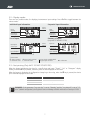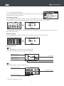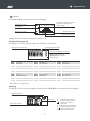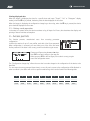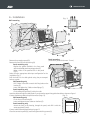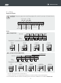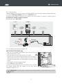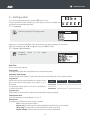
1
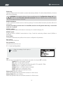
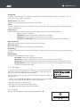
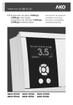
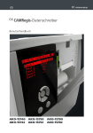
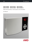
1575H112 Ed.02
GB
CAMRegis Data logger
User manual
AKO-15740
AKO-15742
AKO-15750
AKO-15752
AKO-15780
AKO-15782
1575H112 Ed.02
Pag
Index
Warnings ...........................................................................................................................................3
1.- Presentation..................................................................................................................................4
1.1.- Versions and references......................................................................................................4
1.2.- Maintenance......................................................................................................................4
1.3.- Description ........................................................................................................................5
2.- Operation......................................................................................................................................6
2.1.- Data logging......................................................................................................................6
2.2.- Display modes....................................................................................................................7
2.3.- Fast printing.......................................................................................................................7
2.4.- Consult recorded data........................................................................................................8
2.5.- Battery mode operation....................................................................................................10
3.- Access permits ............................................................................................................................10
4.- Installation..................................................................................................................................11
4.1.- Wiring .............................................................................................................................12
4.2.- Connectivity.....................................................................................................................13
4.3.- Installing the thermal paper roll........................................................................................13
5.- Configuration..............................................................................................................................14
5.1.- Language.........................................................................................................................14
5.2.- System configuration........................................................................................................14
5.3.- Input configuration...........................................................................................................15
5.4.- Text editor........................................................................................................................16
5.5.- Contrast...........................................................................................................................16
6.- Table of parameters.....................................................................................................................17
7.- Specification ...............................................................................................................................18
AKO Electromecánica thanks and congratulates you for purchasing our product, in whose development and manufacture the most innovative
technology has been used, as well as strict production and quality control processes.
Our commitment to satisfy our customers and our continuous efforts to improve every day can be seen in the various quality certifications we
have obtained.
This is a high performance, high technology product. The operation and final performance of the equipment depend on proper planning,
installation, configuration and commissioning. Read this manual carefully before installation, and always follow its instructions.
Only qualified personnel should install or perform technical assistance on this product.
This product is designed to be used in the applications described in the product manual. AKO Electromecánica gives no guarantee of its
operation in any use not foreseen in the manual, and is not responsible for any damage resulting from improper use, configuration,
installation or commissioning.
It is the responsibility of the installer and the customer to comply with and ensure others comply with all regulations applicable to
installations incorporating our products. AKO Electromecánica is not responsible for any damage caused by non-compliance with regulations.
Follow strictly the instructions given in this manual.
To maximise the service life of our equipment, these recommendations should be followed:
Do not expose electronic equipment to dust, dirt, water, rain, humidity, high temperatures, chemicals or corrosive substances
of any sort.
Do not submit the equipment to blows or vibrations nor try to manipulate it differently from shown in the manual.
Never exceed the specifications and limitations indicated in the manual.
Always respect the specified ambient working and storage conditions.
During and after installation, avoid leaving loose, broken, unprotected or damaged wiring, since they might constitute a risk
for the equipment and its users.
AKO Electromecánica reserves the right to make any non-metrology modification to the documentation or the equipment without previous
notice.
2
1575H112 Ed.02
WARNINGS
-The unit must be installed in a location protected from vibrations, water and corrosive gases, where
the ambient temperature does not exceed that shown in the technical data.
-In order for the controllers to have IP65 protection, the gasket between the equipment and the perimeter of the
panel cut-out where the panel is to be installed must be correctly installed.
-Use only probes supplied by AKO to ensure proper operation of the equipment.
-To get a correct reading, the probe must be placed in a location without any external heat influences except for
the temperature which is being measured or controlled.
-The probe and its cable must be installed in a separate conduit away from any other type of conduits.
-If the NTC probe is being extended, always use shielded cable and connect the grid to ground. In these cases,
the maximum deviation is 0.25 ºC between -40 ºC and +20 ºC (maximum of 1,000 m with a minimum section
of 0.5 mm2). AKO-15586 cable is recommended.
-Always disconnect the power supply before making any connections.
-The power supply circuit must be provided with a main switch rated at least 2 A, 230 V, located close to the
equipment.
-The power cable must be H05VV-F or H05V-K. The section to be used will depend on local regulations, but
should in no case be less than 1 mm2.
-Using the logger contrary to the manufacturer's instructions may affect the device's safety requirements.
-The graph paper is thermal and therefore if you wish to keep the graphs for a long time you must make
photocopies. The length of an input's graph is less than the length of a sheet of DIN A4.
-With the recording frequency or interval set to 15 minutes, the loggers keep the information in memory for over
one year. They therefore ensure compliance with UNE EN 12830, enabling graphs to be printed or displayed
when required.
-If frequencies of less than 15 minutes are configured, in order to comply with UNE EN 12830, the graphs
must be printed before the memory ends and be kept for one year.
Units that incorporate rechargeable electrical accumulators:
This unit has built-in accumulators which must be replaced when the autonomy of the unit is less than
the duration shown in the specifications. At the end of the unit's life, the accumulators must be taken to
a selective disposal centre or returned to the equipment manufacturer.
Periodic checks:
In accordance with standard UNE EN 12830, maintenance must include the checks indicated in the
UNE EN 13486 standard (only with the AKO-14931 NTC probes).
IMPORTANT: Prior to the installation of the equipment, connect the
battery cable (1) to the panel connector (2).
1
2
3
1575H112 Ed.02
1.- Presentation
CAMRegis is a solution for capturing, storing and recording temperatures and other physical variables such as
humidity and pressure.
They have an internal memory that allows data storage of up to 6 years recording at 30 minutes, and a battery that
provides up to 6 hours for recording data and up to 3 months for maintenance of date and time in the event of a
power failure.
The data stored can be displayed on screen or printed by means of the unit's own printer (depending on the
model).
1.1.- Versions and references
MODELS
INPUTS
AKO-15740
10
NO
AKO-15742
10
YES
AKO-15750
5
NO
AKO-15752
5
YES
AKO-15780
2
NO
AKO-15782
2
YES
RELAYS
(250V, cos j=1)
POWER SUPPLY
Max. alarm: 6A SPDT
Max. alarm: 6A SPDT
100 - 240 Vac
50/60 Hz ± 3 Hz
PRINTER
1.2.- Maintenance
Clean the surface of the alarm using a soft cloth, soap and water. Do not use abrasive detergents, petrol, alcohol or
solvents.
4
1575H112 Ed.02
1.3.- Description
Battery
status
Full charge
Charging
Date
Alarm status*
Defective or not
connected (blinking)
Time
Day of
the week
Paper input lever**
Paper feed key**
Print/
fast print/
stop print key**
Screen
Search arrows
Escape key
Help key
Printer lid**
Keypad functions
Vertical scrolling/Change value.
Changes the input to be displayed.
ESC Allows you to exit without saving changes (Programming).
Returns to the previous menu or exits programming.
¿
Horizontal scrolling.
Changes display modes
SET
Confirms selection.
Pressing it for 5 sec. the
programming menu is accessed.
Displays the help text for the parameter or
function selected.
NOTE: The alarms are silenced by pressing any of the above keys.
On models with printer.
Paper feed
On standby, prints the graph of the last
calendar week logged.***
From the logger menu, prints the data or
the graph shown on the screen.
From the alarm menu, prints the alarm log.
Stops any printing in progress.
*Alarm status
Err
Alarm activated
Alarm signal activated
Alarm signal muted/disabled
Maximum alarm
Minimum alarm
Digital input activation
Probe error (open/crossed/off-scale)
** Only AKO-15742/15752/15782
*** If the recording interval is 15'.
5
1575H112 Ed.02
2.- Operation
2.1.- Data logging
The logged data are saved in log blocks, each log block saves a given period of time depending on the “Log
interval” parameter, as shown:
Log interval
15 min.
Log interval
30 min.
Log block
24 hours
Start
Log interval
5 min.
End
00:00
23:59
1 week
Monday 00:00**
Sunday 23:59**
2 weeks
Monday 00:00**
Sunday 23:59**
** According to parameter “Log start day”
If any change is made in the configuration that affects the parameters indicated on page 17, the ongoing block is
closed and a new one is started with the new configuration.
All the blocks have the same capacity and start at the same time and on the same day of the week (if the
recording interval is 15 or 30 min.).
Whenever a new block starts, it is identified with its starting date and time.
EXAMPLES (Recording interval 15 min.):
1 If the device is started on Wednesday 4 March 2015 at 14:02, the recording interval is 15 min.
and the recording starting day is Monday, the first block will have as Monday 2 March 2015 at
00:00 as its starting date, but will not contain any data until Wednesday at 14:15.
Start
Monday
02/03/2015
00:00
Log block
Without data
With data
Wednesday 14:15
End
Sunday
08/03/2015
23:59
2 If changes are made to the recorder's configuration on Thursday 19 March 2015 at 09:40, the
ongoing block is closed and a new one is started. Therefore, there will be two recording blocks with the
same name but with different content, as shown:
Start
Monday
16/03/2015
00:00
With data
Without data
1
2
6
Log block
Without data
With data
Thursday 09:45
End
Sunday
22/03/2015
23:59
1575H112 Ed.02
2.2.- Display modes
There are four possible modes for displaying instantaneous input readings. Press P or O to toggle between the
various modes:
Individual input information
Sequential input information
Alarm
status*
Input
reading
Input
reading
Description
of the input
Description
of the input
List of inputs
Summary of inputs
(only AKO-15740/AKO-15742)
Alarm
status*
Description
of the input
Input No.
Probe failure
Input disabled
Input reading
Input disabled
Input reading
* Alarm status
R Alarm activated
< Maximum alarm
( Alarm signal activated
= Minimum alarm
> Alarm signal muted/disabled
Digital input activation
Err Probe error
2.3.- Fast printing (Only AKO-15742/15752/15782)
When the logger is displaying the data for a specific date and input (“Graph”, “List” or “Histogram” display
modes), when the D key is pressed, the device prints the data displayed on the screen.
When the logger is displaying the configuration change log or alarm log, when the D key is pressed, the device
prints the data displayed on the screen.
Log interval
Period to be printed
5 min.
24 hours
15 min.
Last complete week
30 min.
14 days
EXAMPLE: If the parameter “Log start day” is set at “Monday” and the “Log interval” is set at “15
min.” (default configuration), the log block starts on Monday at 00:00 and closes on Sunday at 23:59.
7
1575H112 Ed.02
2.4.- Consult recorded data
This allows displaying and printing the data logged by the device, press the SET
key and select one of the four options:
Selection by calendar
Use the P, O, N and Q keys to select a date and press SET, the log block
corresponding to the selected date will be displayed. Each block contains the data for a full week**.
SET
If the selected day contains more than one log block, you must select one of the available blocks. The crossed out
days do not contain data.
Selection by block
Use the N and Q keys to select a log block, each log block contains the data for a full week**.
SET
Data presentation
Graph
Use the P and O keys to move the selector for displayed logs.
Use the N and Q keys to change the input to be displayed.
Maximum scale value
Log selector
Displayed log value
Minimum scale value
Date and time of the log displayed
Displayed input indicator
List
Use the N and Q keys to move around the logs.
Displayed input indicator
Displayed log value
Date and time of the log
** Only if the log interval is 15 min.
8
1575H112 Ed.02
Histogram
Use the N and Q keys to change the input to be displayed.
This displays the values contained
in the block selected by way
of percentages
Maximum scale value
See example
Minimum scale value
Maximum scale value
Displayed input indicator
Example: 38% of the records correspond to the value 0.5 ºC.
Configuration changes log
This displays a list with the changes made in the configuration of the device.
Date and time of the change
Type of change (see table)
User who changed the configuration
U0: Non-configured users
U1/2/3/4/5: User 1/2/3/4/5
(See page 10)
GL:1
GL:2
GL:3
GL:4
GL:5
GL:6
GL:7
GL:8
GL:9
GL:10
GL:11
GL:12
Date/Time
Date format
Automatic time change
Log interval
Log start day
Temperature units
Mute Alarm
Delete log
Default parameters
Modbus adress
Modbus speed
Acces rights
Types of configuration changes
GL:13 User name 1
GL:14 User password 1
GL:15 User name 2
GL:16 User password 2
GL:17 User name 3
GL:18 User password 3
GL:19 User name 4
GL:20 User password 4
GL:21 User name 5
GL:22 User password 5
GL:23 Idioma
GL:24 Contrast
Ix: 00
Ix: 01
Ix: 02
Ix: 03
Ix: 04
Ix: 05
Ix: 06
Ix: 07
Ix: 08
Ix: 09
Ix: 10
Input type
Value at 4 mA
Value at 20 mA
Offset
Display units
Description
Enable alarm
Max. alarm level
Min. alarm level
Alarm delay
Alarm output
Ix: I0 (Input 1) - I9 (Input 10)
Alarm log
This displays a list with the alarms logged in the device, use the P and O keys to select the input to be displayed.
Logged temperature
Alarm type
Alarm date and time
9
<
=
Maximum alarm activation
Minimum alarm activation
Digital input activation
E
Probe error
X < Maximum alarm deactivation
X = Minimum alarm deactivation
X
Digital input deactivation
X E Probe error deactivation
1575H112 Ed.02
Printing displayed data
When the logger is displaying the data for a specific date and input (“Graph”, “List” or “Histogram” display
modes), when the D key is pressed, the device prints the data displayed on the screen.
When the logger is displaying the configuration change log or alarm log, when the D key is pressed, the device
prints the data displayed on the screen.
2.5.- Battery mode operation
In the event of a power failure, the device continues to log all inputs for 6 hours, but deactivates the display and
printing of data to minimise consumption.
3.- Access permits
This function prevents unauthorised users from accessing parameter
configuration.
It allows the creation of up to 5 user profiles, each with a four figure password.
When configuration is accessed, you must select one of the users and enter
his/her password. If the latter is not correct, you will not be able to gain access.
Change each figure using the N and Q keys.
Press SET to accept it and go to the next one.
When you press SET on the last figure, if the code is correct, you gain
access the configuration menu.
The “Configuration changes log” allows the user who has made changes in the configuration of the device to be
identified.
If a user enters the wrong password three times in a row, this user's access to the configuration will be blocked. In
order to unblock it, the device will ask for a specific numerical key, which can be found in the following table:
1
2
3
4
5
6
7
8
9
10
2421
5832
1294
5119
0547
8168
3632
5901
8533
1942
11
12
13
14
15
16
17
18
19
20
7145
3044
6197
8134
4800
3319
0237
5565
2098
4291
10
1575H112 Ed.02
4.- Installation
(fig. 1)
Wall mounting
F
B
A
C
D
M
E
G
H
214 mm
Panel mounting
-Remove the connection panel (D).
(maximum panel thickness: 3 mm)
-Remove the front (B) from the housing (A).
Panel mounting only
A
I
-Replace the gasket installed in the front panel
B
J
with the included panel mounting gasket (K).
-Make a hole of the specified size in the panel
(Fig.2).
-Select the most appropriate cable input configuration for the
L
installation (fig. 1).
-Drill the holes for the cable glands using the pre-stamped
holes as a guide.
Wall mounting only
-Drill 3 holes in the wall to match the fixing holes on the
M
housing (E).
K
-Insert and tighten the 3 bolts and wall plugs (F).
Panel mounting only
-Finish drilling the top holes (L) with a 4 mm bit.
-Insert the cables through the cable glands. If you choose the upper inlets, guide the cables as shown on figure 1.
-Connect the battery cable to the panel connector (Page 13).
(fig. 2)
Wall mounting only
214 mm
-Fit the front of the housing (B).
-Insert and tighten the two screws on the front (G).
Panel mounting only
-Attach the front to the housing, through the panel, and affix it with the
PANEL CUTOUT
screws provided (G and J).
-Connect cables following the drawings in page 12.
-Close the connection panel (D), insert and tighten the fixing screws (H).
11
G
1575H112 Ed.02
4.1.- Wiring
Supply and outputs
CAUTION: The power supply circuit should be equipped with a switch for turning it off, located close to
the device.
6 A cos j = 1 250V
1
2
3
4
5
6
7
8
9
10 11 12 13 14 15
Tr
+
Outputs of
+12 Vcc *
Input
Output
Output
100- MAXIMUM MINIMUM
240 Vac ALARM
ALARM
Tr
G
nd
NO C NC NO C NC
Probes
AKO-15740/15742
2
INPUT NO.
1
4
6
3
10
8
7
5
9
16 17 18 19 20 21 22 23 24 25 26 27 28 29 30
NTC
Pt1000
Example of connection of other probes:
DIGITAL
INPUT
4-20 mA
3 wires
n
4-20 mA
2 passive wires
n
n
n
**
x x x
n
**
**
x x x
n
n
1
2
n
**
x x x
AKO-15750/15752/15780/15782
INPUT NO.
4-20 mA
2 active wires
x x x
Only AKO-1575x
3
4
5
16 17 18 19 20 21 22 23 24 25 26 27 28 29 30
NTC
Pt1000
Example of connection of other probes:
Pt100
DIGITAL
INPUT
n
n
x x x
x x x
4-20 mA
3 wires
**
n
x x x
**
4-20 mA
2 passive wires
4-20 mA
2 active wires
n
n
x x x
x x x
* The sum of the 4 outputs must not exceed 250 mA
** Connect to one of the + 12V output terminals (terminals 9 al 12) (Not available in battery mode operation)
For more information about the connection of humidity probes consult Manual 358004001 on our website: www.ako.com
12
1575H112 Ed.02
4.2.- Connectivity
CAMRegis loggers have a port for connection of RS485 (MODBUS) data, that allow remotely managing them using
a PC with the SOFTRegis, AKONet software or an AKO-5011 server.
A different address must be assigned for each device in the same network, this address is defined using the
Configuration - Modbus Address parameter.
Recommended cable: AKO-15586
CAMRegis
CAMCtrl
SET
ESC
SET
?
ESC
?
AKO controllers
with communication
13 14 15
TrTr+
Gnd
PC +
AKONet
AKO-80039
AKO-5011
+
GND
RS-485
LAN
4.3.- Installing the thermal paper roll
AKO-15742/15752/15782 only
-With the unit connected to the network, open the front cover and
push the release lever (1) back.
1
-Place the paper roll in the position shown on the image.
-Push the end of the paper through the bottom slot of the printer
until the latter starts to pull it. When the paper comes out of the top
slot, return the release lever to its initial position, the printer is ready
to print.
-Press the E key to feed the paper through.
-Press the D key for express printing.
To print data, the data logger has to have at least one entry recorded.
The required printing time will depend on the entry interval
configuration (default is 15').
IMPORTANT: The printer paper is thermal and can only be printed on one side. Make sure you insert it
properly.
13
1575H112 Ed.02
5.- Configuration
To access the programming menu, press the SET key for 5 secs.
If access permits have been activated, you must select one of the 5 available users
and enter the corresponding password.
5.1- Language
Defines the language of the logger menus.
Allows you to change the language of the menus and texts in general displayed on the screen.
Select the language using the N and Q keys, then press SET to accept.
5.2- System configuration
Parameters related
configuration.
to
the
logger's
Date/Time
Set the current date and time.
Date format
It changes the way the date is displayed on the screen and the printer.
Automatic time change
It allows changes from summer / winter time to be made automatically (only in the European Union).
Log interval
Defines the time that passes between the capture of one
piece of data and the next. Allows you to choose 5, 15 or
30 minutes.
This parameter affects certain of the unit's characteristics
as shown in the table.
Recording
interval
Storage capacity
5 min.
> 5 months
Previous day
15 min.
3 years (aprox.)
1 calendar week
30 min.
6 years (aprox.)
2 calendar weeks
Log start day
It determines on what day of the week each recording block starts (see page 6).
Temperature units
It sets the temperature to be displayed in ºC or in ºF.
Mute alarm
It configures alarm behaviour when any key is pressed:
No: The alarm cannot be silenced.
Buzzer only: The warning tone is disconnected but the alarm relay is still activated.
Relay only: The alarm relay is deactivated but the sound is still active.
Buzzer & Relay: Both the alarm relay and the sound are deactivated.
14
Fast printing
1575H112 Ed.02
Delete logs
It deletes all data saved in the recorder to present date (memory deletion). To avoid accidental deletions, the device
will ask for confirmation.
WARNING: This operation deletes all data recorded (except the “configuration change log”) by
the device to date. This data cannot be recovered. During the deletion process, the device might
not respond for about 10 seconds.
Default parameters
If “YES” is selected, the device returns to the factory settings. To avoid accidental activations, the device will ask for
confirmation.
The data recorded to present date is not modified, but the recording block under way is closed and
a new one is opened.
MODBUS address
It sets the MODBUS address of the device if connecting it in a network (See page 13).
MODBUS speed
It sets the speed of MODBUS communications in bps, Consult the monitoring software manual (AKONet or
SOFTRegis).
Access rights
It activates or deactivates user profiles to limit access to configuration of parameters.
User name n
It sets the name of each user.
User password n
It sets the password of each user.
5.3.- Input configuration
It allows the settings of each input to
be edited.
Type
Select the type of input depending on the element connected to it and press SET to validate.
Disabled: There is no element connected.
NTC: There is an NTC probe connected.
Pt100: There is a PT100 probe connected (only AKO-1575x and AKO-1578x).
Pt1000: There is a Pt1000 probe connected.
4-20mA: There is a 4-20mA converter connected.
DI-NO: Digital input, normally open contact.
DI-NC: Digital input, normally closed contact.
Value at 4mA (Sólo para 4-20mA)
Defines the equivalent value of the 4-20mA converter for a 4mA current.
Value at 20mA (Sólo para 4-20mA)
Defines the equivalent value of the 4-20mA converter for a 20mA current.
15
1575H112 Ed.02
Description:
It allows a name with up to 10 characters to be entered in order to describe the input ( Cold Room 1, Fruit, Ext.
probe, etc.), using the built-in text editor.
Display units (Only 4-20mA)
Define the units to be displayed using the built-in text editor.
Offset
It allows a possible reading error in the probe to be corrected. This may be very useful when it cannot be put into
the most suitable place.
Enable alarm
It allows the maximum and minimum alarms to be activated. Select one of the following options:
No: The alarms are disabled.
Minimum: Only the minimum value reached alarm is enabled.
Maximum: Only the maximum value reached alarm is enabled.
Minimum and Maximum: The maximum and minimum value reached alarms are enabled.
Max. alarm level
Defines the maximum value from which the alarm will be activated.
Min. alarm level
Defines the minimum value at which the alarm will be activated.
Alarm delay
It configures the delay time from when the maximum or minimum value is reached until the alarm is activated (in
minutes).
Alarm output
It configures the behaviour of the alarm output:
No output: The alarm is only displayed on screen.
Buzzer only: The alarm is displayed on the screen and it activates an acoustic signal.
Relay only: The alarm is displayed on the screen and it activates the maximum or minimum alarm relay.
Buzzer & Relay: The alarm is displayed on the screen, it activates an acoustic signal and activates the
maximum or minimum alarm relay.
5.4.- Text editor
In order to facilitate the interpretation of data, you can customise the names of
each input with a description of up to 10 characters. If the input type is 420mA, you will also be able to edit the display units.
The lower section of the screen shows the changes carried out during the
editing process.
- Use the arrow keys P, O, N and Q to scroll through the various available
characters and options and the SET key to confirm the selection.
- Select 9 to delete the highlighted text.
- Select L or K to scroll within the text being edited.
- Select 8 to save your changes and exit the edit menu.
5.5- Contrast
Set the screen's contrast level by pressing keys P and O.
50
16
1575H112 Ed.02
6.- Table of parameters
Configuration
B
B
B
B
B
B
B
Description
Date/Time
Date format:
Day/Month/Year Month/Day/Year Year/Month/Day
Automatic time change
Yes
No
Log interval
5
15 30
Log start day
Monday Tuesday Wednesday
Thursday
Friday
Saturday Sunday
Temperature units
ºC ºF
Mute Alarm
No Buzzer only Relay only Buzzer & Relay
Delete log
Yes No
Default parameters
Yes No
Modbus adress
Modbus speed
9600 19200 38400 57600
Acces rights
Yes No
User name 1
User password 1
User name 2
User password 2
User name 3
User password 3
User name 4
User password 4
Units
Min.
bps
Min
1
5
Def
1
D/M/Y
Yes
15
Max.
31
30
-
Monday
-
1
0
0
0
0
ºC
Buzzer o.
No
No
1
9600
No
USER 1
1234
USER 2
1234
USER 3
1234
USER 4
1234
255
9999
9999
9999
9999
Language
Idioma:
Español
Italiano
Description
English
Français
Português русский
Units
Min
Deutsch
Def
Max.
-
Input n configuration
B
B
B
B
Type:
Disabled
4-20mA
Value at 4 mA
Value at 20 mA
Description
Display units
Offset
Enable alarm No
Max. alarm level
Min. alarm level
Alarm delay
Alarm output
Description
NTC
Pt100*
DI-NO
DI-NC
Minimum
Maximum
No output
Relay only
Units
Min
Def
-
Dis.
-
min.
-999.9
-999.9
-20.0
-999.9
-999.9
0
0
100
Input n
0.0
No
999.9
-999.9
0
999.9
999.9
20.0
999.9
999.9
120
-
No output
-
Pt1000
Minimum and Maximum
Buzzer only
Buzzer + Relay
* AKO-1575x and AKO-1578x Only.
B
When you change any of these parameters, the log block closes and a new one starts.
17
Max.
1575H112 Ed.02
7.- Specification
Range varies by type of probe configured:
NTC (AKO-14931) . . . . . . . . . . . . . . . . . . . . . . . . . . . . . . . . . . . . . . . . . . . . . . . . . . . . . . -50 ºC to 105 ºC (-58.0 ºF to 221 ºF)
Pt1000 . . . . . . . . . . . . . . . . . . . . . . . . . . . . . . . . . . . . . . . . . . . . . . . . . . . . . . . . . . . . . . -150ºC to 550ºC (-238 ºF to 1022 ºF)
4-20 mA. . . . . . . . . . . . . . . . . . . . . . . . . . . . . . . . . . . . . . . . . . . . . . . . . . . . . . . . . . . . . . . . . . . . . . . . . . . . . . . . -999 to 999
AKO-1575x and AKO-1578x only
Pt100 (AKO-1558xxx / AKO-1559x) . . . . . . . . . . . . . . . . . . . . . . . . . . . . . . . . . . . . . . . -150 ºC to 590 ºC (-238 ºF to 1094 ºF)
Resolution . . . . . . . . . . . . . . . . . . . . . . . . . . . . . . . . . . . . . . . . . . . . . . . . . . . . . . . . . . . . . . 0.1 ºC from -99.9 to 99.9, elsewere 1 ºC
Thermometric precision
NTC (AKO-14931) . . . . . . . . . . . . . . . . . . . . . . . . . . . . . . . . . . . . . . . . . . . . . . . . . . . . . . . . . . . . from -50 ºC to 105 ºC ±1 ºC
Pt100 . . . . . . . . . . . . . . . . . . . . . . . . . . . . . . . . . . . . . . . . . . . . . . . . . . . . . . . . . from -100 ºC to 100 ºC ±2 ºC, elsewere ±2 %
Pt1000 . . . . . . . . . . . . . . . . . . . . . . . . . . . . . . . . . . . . . . . . . . . . . . . . . . . . . . . . from -100 ºC to 100 ºC ±2 ºC, elsewere ±2 %
4-20 mA . . . . . . . . . . . . . . . . . . . . . . . . . . . . . . . . . . . . . . . . . . . . . . . . . . . . . . . . . . . . . . . . . . . . . . . . . . . . . . . . ±1% (mA)
Designation with NTC
. . . . . . . . . . . . . . . . . . . . . . . . . . . . . . . . . . . . . . . . . . . . . . . . . . . . . . . . . . . . . . . . . . . . . . . . . . . . EN 12830,S,A,1,-40 ºC +40 ºC
. . . . . . . . . . . . . . . . . . . . . . . . . . . . . . . . . . . . . . . . . . . . . . . . . . . . . . . . . . . . . . . . . . . . . . . . . . . . EN 13485,S,A,1,-40 ºC +40 ºC
Power supply . . . . . . . . . . . . . . . . . . . . . . . . . . . . . . . . . . . . . . . . . . . . . . . . . . . . . . . . . . . . . . . . . . . . . . . . 100 - 240 V~ 50/60 Hz
Maximum power absorbed AKO-157x0. . . . . . . . . . . . . . . . . . . . . . . . . . . . . . . . . . . . . . . . . . . . . . . . . . . . . . . . . . . . . . . . 10 VA
AKO-157x2. . . . . . . . . . . . . . . . . . . . . . . . . . . . . . . . . . . . . . . . . . . . . . . . . . . . . . . . . . . . . . . . 20 VA
Ambient working temperature . . . . . . . . . . . . . . . . . . . . . . . . . . . . . . . . . . . . . . . . . . . . . . . . . . . . . . . . . . . . . . . . . . . 0 ºC to 45 ºC
Ambient storage temperature . . . . . . . . . . . . . . . . . . . . . . . . . . . . . . . . . . . . . . . . . . . . . . . . . . . . . . . . . . . . . . . . . . -30 ºC to 70 ºC
Alarm relays . . . . . . . . . . . . . . . . . . . . . . . . . . . . . . . . . . . . . . . . . . . . . . . . . . . . . . . . . . . . . . . . . . . . . . . . . . . . . . . . . . . SPDT 6 A
Double insulation between supply, secondary circuit and relay output.
Installation category . . . . . . . . . . . . . . . . . . . . . . . . . . . . . . . . . . . . . . . . . . . . . . . . . . . . . . . . . . . . . . . . II according to EN 61010-1
Pollution classification. . . . . . . . . . . . . . . . . . . . . . . . . . . . . . . . . . . . . . . . . . . . . . . . . . . . . . . . . . . . . . . II according to EN 61010-1
Battery . . . . . . . . . . . . . . . . . . . . . . . . . . . . . . . . . . . . . . . . . . . . . . . . . . . . . . . . . . . . . . . . . . . . . . . . . . . . Li-Polymer + cell R2032
Internal buzzer
NOTE FOR THE SPANISH MARKET
This device complies with the UNE EN 12830 standard
18
1575H112 Ed.02
19
We reserve the right to supply materials that might vary slightly to those described in our Technical Sheets. Updated information is available on our website.
351575112 REV.01 2015
AKO ELECTROMECÁNICA, S.A.L.
Av. Roquetes, 30-38 | 08812 Sant Pere de Ribes | Barcelona | España
Tel. (34) 938 142 700 | Fax (34) 938 934 054 | e-mail: [email protected] | www.ako.com