1
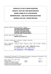
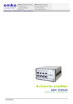
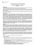
RR550BIGAS TFT 1 2 INDEX 1 2 3 4 5 6 7 8 GUARANTEE ............................................................................................................................. 5 WARNINGS ................................................................................................................................ 5 environmental notes ..................................................................................................................... 5 GENERAL INFORMATION ...................................................................................................... 6 4.1 PURPOSE OF THE MANUAL ............................................................................................ 6 4.2 SAFETY FEATURES ........................................................................................................... 7 TECHNICAL SPECIFICATIONS .............................................................................................. 8 5.1 TECHNICAL CHARACTERISTICS ................................................................................... 8 5.2 INCLUDED ACCESSORIES ............................................................................................... 9 InstallaTION ................................................................................................................................ 9 6.1 RECOMMENDATIONS FOR THE CORRECT USE OF THE DEVICE .......................... 9 6.2 INSTALLATION .................................................................................................................. 9 6.3 PREPARATION OF THE STATION .................................................................................. 9 6.4 PERFORMABLE OPERATIONS ...................................................................................... 10 6.5 SAFETY DEVICES ............................................................................................................ 10 DESCRIPTION OF THE STATION ......................................................................................... 11 7.1 MAIN COMPONENTS ...................................................................................................... 11 7.2 MESSAGES ON THE DISPLAY ....................................................................................... 12 7.3 PREPARATION OF THE STATION ................................................................................ 13 7.4 KEYBOARD ....................................................................................................................... 14 7.4 KEYBOARD ....................................................................................................................... 14 7.5 PROGRAM CHOICE ......................................................................................................... 14 7.6 INDICATIONS ON THE DISPLAY .................................................................................. 15 FuNCTIONS .............................................................................................................................. 16 8.1 PRESSURE TEST............................................................................................................... 16 8.1.1 Manual WSC function ................................................................................................. 17 8.1.2 Automatic WSC function ............................................................................................. 17 8.1.3 Pressure trends ............................................................................................................. 17 8.2 MANUAL CYCLE ............................................................................................................. 17 8.2.1 Recovery ...................................................................................................................... 17 8.2.2 Vacuum ........................................................................................................................ 17 8.2.3 Oil/Additive injection .................................................................................................. 18 8.2.4 Gas Recharge ............................................................................................................... 18 8.3 SEMI-AUTOMATIC CYCLE ............................................................................................ 18 8.4 AUTOMATIC CYCLE ....................................................................................................... 18 8.5 INTERNAL BOTTLE RECHARGE .................................................................................. 19 Connect the red hose of the station to an external bottle containing the proper gas. .............. 19 Select “Recharge internal bottle” from the main menu .......................................................... 19 Confirm your choice ............................................................................................................... 19 Set the gas quantity that you wish to recover.......................................................................... 19 8.6 DATABASE ........................................................................................................................ 19 8.6.1 Database Updating ....................................................................................................... 19 8.7 DEVICE FLUSHING CLEANING .................................................................................... 20 8.8 RECYCLING CLEANING ................................................................................................. 20 8.9 NITROGEN TEST .............................................................................................................. 20 8.10 USER SELECTION ........................................................................................................ 21 8.11 UTILITY.......................................................................................................................... 21 8.11.1 User Management ........................................................................................................ 21 8.11.2 Operation register ......................................................................................................... 21 3 8.11.3 Oil Setting .................................................................................................................... 21 8.11.4 Recharge Hose Selection ............................................................................................. 21 8.11.5 MULTIPASS Mode ..................................................................................................... 21 8.11.8 Gas Type ...................................................................................................................... 22 8.11.9 Configuration ............................................................................................................... 22 8.11.10 Technical Service ..................................................................................................... 22 8.11.11 Printing Heading....................................................................................................... 22 8.12 CLOCK ............................................................................................................................ 23 8.13 END ................................................................................................................................. 23 9 MAINTENANCE ...................................................................................................................... 23 9.1 PUM OIL ............................................................................................................................. 23 9.2 OIL REFILL ........................................................................................................................ 24 9.3 PUMP OIL REPLACEMENT ............................................................................................ 24 9.4 DEHYDRATING FILTER REPLACEMENT ................................................................... 24 10 INFORMATION ON RESIDUAL RISKS ................................................................................ 25 4 1 GUARANTEE The device has a guarantee period of 12 months from the date of delivery. Within the guarantee the compressor and the vacuum pump are not included, because it can occur, that the compressor is being treated with a different oil than the recommended one. 2 WARNINGS This symbol is being used if the instructions of the manual are not being respected or a false interpretation of the instructions is present this can cause injuries to people. To integrate the specifications of the manual, the following use indications are reported: Follow the station during the movement and brake it during the use; Do not expose the station at ambient temperature > 45 °C; the outside use must be limited to the strictly operation-necessary time; Do not use the device in presence of potentially explosive atmosphere; Use the station in rain-protected environments. 3 ENVIRONMENTAL NOTES NOISE The Machine presents a Lep,d value lower than 70 dB(A). If positioned in areas with a noise value of more than 80 dB(A), the employer must form and inform the operator of the risks from exposure to the noise and must take the necessary precautions according to the authorized doctor. PACKAGING Do not throw away the packaging, separate it according to the type of material (eg. cardboard, wood, plastic material, etc.) and dispose of them in conformity with the local and national laws in force. OUT OF ORDER DISPOSAL At the end of the Machine’s working life: Disactivate the Machine, by disconnecting it from the electric power supply and cutting the supply line cable; Disassemble the Electronic Panel and the related electronic board-card; Disassemble the components, separating the various types. At the end of the Machine’s working life, the parts, separated by the type of material, had to be disposed in conformity with the local and national laws in force. For the electric and electrenic devices, called Electrics and electronics Equipments (WEEE), according with EC Directives 2002/95/CE, 2002/96/CE and 2003/108/CE, the Manufacturer specifies: NOT dispose of the equipment as municipal waste and separate collection is mandatory; Ask the retailer about collection points authorised for regular disposal; Stick to the standards for correct waste management, to prevent potential effects on the environment and human health; The onside symbol indicates that separate collection of waste electrical and electronic equipment is mandatory for scrapping. 5 4 4.1 GENERAL INFORMATION PURPOSE OF THE MANUAL This manual is intended for the use and maintenance of the recycling, recovery, vacuum and recharge station. It is absolutely necessary to read this manual attentively before using the device. This station is equipped with security devices designed to prevent injuries to the operator. The manufacturer disclaims any liability arising from the misuse of the station and from the removal of the security devices by the user. The instruction manual is an integral part of the device and must always be stored close to the device , even in case of sale. The device is being identified by an identification plate which shows the model, the year of manufacture and the serial number. The identification plate is located on the side of the device (fig.1). Figure 1 – Identification plate which shows model, year of manufacture and serial number WARNING THE DEVICE IS ONLY SUPPOSED TO BE USED BY TECHNICIANS WHO ARE FAMILIAR WITH REFRIGERATION SYSTEMS AND GASES AND WITH THE DAMAGES/INJURIES THE DEVICES UNDER PRESSURE MAY CAUSE. THE STATION PERFORMS THE PHASES OF RECOVERY, RECYCLING, VACUUM AND RECHARGE ON A/C SYSTEMS OF CARS AND INDUSTRIAL VEHICLES WHICH CONTAIN R 134A FREON. THE MANUFACTURER DISCLAIMS ANY LIABILITY ARISING FROM THE MISUSE OF OTHER FREON OR FROM THE CONTAMINATION RESULTING FROM THE MISUSE OF THE STATION. 6 4.2 SAFETY FEATURES WHEN WORKING IN PRESENCE OF FREON IT IS ABSOLUTELY NECESSARY TO WEAR PROTECTIVE GLOVES AND GLASSES. USE THE DEVICE IN A WELL-VENTILATED ROOM IN ORDER TO AVOID POTENTIAL FREON INHALATIONS. IF FREON ACCIDENTALLY COMES INTO CONTACT WITH SKIN: 1) SOAK THE AFFECTED AREAS IN WATER; 2) CAREFULLY REMOVE THE CONTAMINATED CLOTHES; ATTENTION: CLOTHES CAN STICK TO THE SKIN IN CASE OF COLD BURN; GET MEDICAL ADVICE. IN CASE OF ACCIDENTAL CONTACT WITH EYES: 1) FLUSH THOROUGHLY WITH WATER; 2) GET IMMEDIATE MEDICAL ADVICE. IF FREON IS ACCIDENTALLY INGESTED: 1) WASH WELL YOUR MOUTH AND DRINK LOTS OF WATER; 2) GET MEDICAL ADVICE. Attention: THE GAS INSIDE THE A/C SYSTEM COULD BE POLLUTED MAKE SURE THAT THE GAS YOU ARE RECOVERING IS R134 or R1234yf AND THAT THE STATION IS SET ON THE CORRECT GAS TYPE IN ORDER TO AVOID CONTAMINATION OF THE TWO GASES. 7 5 TECHNICAL SPECIFICATIONS 5.1 TECHNICAL CHARACTERISTICS If properly set up the station works both with cars and hybrid vehicles and with R134 and R1234yf systems. Below are the main components and the respective characteristics of the station. Compressor: Power: Recovery capacity: (liquid phase) Vacuum pump: Capacity: Vacuum level: Vacuum test: Storage bottle: LCD Display: BP AP gauges: Bottle pressure gauge: Bottle scale accuracy: Bottle weight resolution: Incondensable gas discharge: Current supplì: Loudness: Tube length: Device dimension: Weight: 24-column printer: Types of car: Types of gas: Hermetic with automatic oil reintegration at 9cc 250 watt 400gr/min Single-stage 90lt/min 7x10² Automatic with sound alarm, message on the display and visualization of the vacuum level in mbar Double bottle with automatic heater of 12,5 kg capacity each. Color 5.6” display Analogue and digital display Two analogue gauges located on the two sides of the station. ± 2gr 1gr Automatic 230 V / 50 Hz Under 70dB (measured with class 2 sound level meter according to IEC 651 and IEC 804 standards) 3 mt each 500 x 500 x h 1310 mm 80 Kg Standard Standard cars and hybrid vehicles R134a and R1234yf 8 5.2 6 6.1 INCLUDED ACCESSORIES 1 low pressure hose (3 mt) 1 high pressure hose (3 mt) 1 low pressure quick coupling for R134a 1 high pressure quick coupling for R134a 1 low pressure quick coupling for R1234yf 1 high pressure quick coupling for R1234yf 1 250 g plastic dispenser to inject new, pure oil or oil with additive for standard cars Figure 2–Some of the included accessories 1 250 g plastic dispenser to inject new, pure oil or oil with additive for hybrid vehicles 1 250 g plastic dispenser to drain used oil 1 power supply cable INSTALLATION RECOMMENDATIONS FOR THE CORRECT USE OF THE DEVICE BEFORE SWITCHING-ON THE DEVICE PLEASE CHECK IF THERE IS OIL IN THE VACUUM PUMP. IF OIL IS MISSING FILL IT UP UNTIL YOU REACH THE LEVEL WHICH CAN BE SEEN IN THE SPECIAL WINDOW. USE ONLY MINERAL OIL FOR TYPE AV68 (ART. AV68I) VACUUM PUMPS. 6.2 INSTALLATION The device must be lifted and transported in an upright position. Otherwise there might be oil spill from the vacuum pump and the compressor. The device can be moved only on even floor. It is not recommended to use it on uneven ground outside the workshop. Figure 3 – Identification plate with operating voltage 6.3 PREPARATION OF THE STATION Before starting the device ensure that the power voltage is the same as the one shown on the identification plate close to the side electrical outlet. WARNINGS 9 THE STATION MUST BE CONNECTED TO AN ELECTRICAL OUTLET PROTECTED AGAINST INDIRECT CONTACT IN COMPLIANCE WITH THE RULES IN FORCE IN THE COUNTRY OF USE IT IS ADVISED TO COMPLY CAREFULLY WITH THE HEREINABOVE SAFETY STANDARDS. THEY ARE PROVIDED TO ENSURE THE PROTECTION OF THE PERSONNEL WHO USES THE SYSTEMS FOR PROCESSING FREON UNDER PRESSURE 6.4 PERFORMABLE OPERATIONS If properly set the station is able to perform the phases of recovery, recycling, vacuum, cleaning and charge on A/C systems of cars and industrial vehicles containing R134a and R1234y Freon. The manufacturer disclaims any liability arising from the misuse of the other types of freon. 6.5 SAFETY DEVICES Double safety valve calibrated at 16 bar for the internal bottle Automatic and manual discharge of non-condensable gas through proper valve Compressor thermal protection against overloads (inside the compressor) Electronic alarms for filling over than 80% of the capacity and minimum gas amount necessary for recharges (< 1Kg) Alarm of wrong operation in case of vacuum with the system under pressure Control display of oil level in the pump Electrovalve for complete automatism of the functions Display LCD board with electronic protection (PTC) Protection fuse on the switching-on module Automatic bottle heating (for winter use) 10 7 DESCRIPTION OF THE STATION 7.1 MAIN COMPONENTS The main components of the station are listed below with reference to the images. Figure 4 – Station and components 11 REFERENCES A 5.6” COLOR DISPLAY B ENCODER (or joystick) FOR PROGRAM SELECTION C 9-KEY KEYBOARD AND PRINTER D POWER BUTTON AND FUSE SEAT (on the side) E USB PORT FOR CONNECTION TO A PC (on the side) F QUICK COUPLING (AP and BP) FOR R134a G QUICK COUPLING (AP and BP) FOR R1234yf H DRAWER FOR OIL TANKS (STANDARD-USED-HYBRID) I VACUUM PUMP OIL LEVEL (REAR) L VENITILATION M DRAWER FOR ACCESSORIES N INTERNAL BOTTLE GAUGE R134a O INTERNAL BOTTLE GAUGE R1234yf ( on the side) 7.2 MESSAGES ON THE DISPLAY All signals will be displayed on the LCD display. When switching on the device the display shows the operator’s choice and by confirming with “enter” on “administrator” the following parameters are displayed: Available amount of freon inside the bottle (kg) Ambient temperature High and low pressure Date and time Graphical display of the bottle Indication of the type of gas on which the device is set If an error occurs during the execution of the phases, the display will show an Error message. Error messages will be displayed in the following cases: When a small amount of freon is present in the internal bottle (<1Kg) o In this case the freon has to be recovered from an external bottle When a leak in the A/C system of the cari s detected during the vacuum test When the amount of coolant contained in the internal bottle is too high (> 17,5 kg) and you try to perform the recovery o In this case a charge should be performed in an external container. When you try to perform a “VACUUM” with the A/C station under pressure or if during the vacuum phase a pressure increase occurs (> 0,5 bar). o In this case a recovery should be performed first. When the interval for maintenance (150 h) is overdue. o Replace the internal filter. When you try to perform the recovery (manually) and the pressure of the system under test is less than 0,5 bar . o Empty circuit. 12 When you try to recharge the internal bottle and the external bottle is empty or becomes empty before the set charge finishes. When the recovery from the external bottle is finished, you have to close the tap of the bottle and press the “ENTER” key to recover the gas in the hoses. Quantità di gas insufficiente per poter effettuare il lavaggio del sistema AC; necessari almeno 4kg di gas. Insufficient quantity of gas to perform the flushing of the A/C system; at least another 4kg of gas are required 7.3 PREPARATION OF THE STATION For the preparation of the station please see the following points. 1- There are no opening/closing taps because valves are operated automatically by the station during all processes. 2- Screw the quick-release couplings to the hoses (blue=low pressure-red=high pressure) (Ref. Figure) Figure 5 – Quick couplings for R134a 3- Plug in the power plug and turn the general switch on. 4- Read on the display the amount of available freon in the internal bottle and the type of selected gas. 5- Fill in the special tank (standard or hybrid) with new oil (in case add some tracer) and with the special synthetic oil for refrigeration. The station is designed to work with special aluminum vacuum packed bags. Figure 7 – Oil Dispenser: 1. New Oil (and additive) for cars 2. Used Oil 3. New Oil (and additive) for hybrid cars Figure 6 – Synthetic oil for refrigeration R134 - item 21CR (optional) 13 7.4 7.4 KEYBOARD KEYBOARD “Arrow” key to move “Enter” key to confirm “C” key to delete “Print” key to print “Database” key to access to the current database “F” key for extra functions Encoder (or Joystick ) for rapid selections (turn to move – press to confirm selection) Figure 8 – Display details Figure 7.5 9 – Keyboard details PROGRAM CHOICE Access to the main menu (when the station is in standby): - Press the Encoder or the Enter key on the keyboard to enter the main menu; How to select the functions with the encoder: - Rotate the encoder clockwise or anti-clockwise to select the function. - Press the encoder to confirm your choice. - Go to “Exit” or to “Cancel” to exit or cancel the inserted data (depending on the menu or on the selected function). - The selected parameters are highlighted by a Blue area. - The choice or the possible change of the selected parameter is highlighted in Yellow. How to select the funtions with the keyboard: - Use the arrow key to select the function. - Press “Enter” to confirm your choice. - Press “C” to exit or to cancel (depending on the menu or on the selected function). - The selected parameters are highlighted by a Blue area. 14 - The choice or the possible change of the selected parameter is highlighted in Yellow. Note: it is possible to use the encoder and the keyboard in a combined way; for example you can select a function with the encoder and confirm your choice with “Enter”. 7.6 INDICATIONS ON THE DISPLAY On the standby display different reference values are present. In the following image a screen with the read sizes is shown The image was divided into more fields in order to ensure a more specific description. Figure 10 – Standby display A. Date/time B. Quantity of available gas in the internal bottle with graphic and numerical indication C. Gas temperature (boiling point – bubble/dew point) D. Gas type on which the station is set E. Low pressure value with graphic and numerical indication and full scale value F. High pressure value with graphic and numerical indication and full scale value By pressing the “F” function key when the letter “F” is displayed, the available parameters will be shown. By pressing the “F” function key after a cycle, the last performed operations will be displayed. Help or alarm messages are highlighted on the display when using the A/C station. 15 8 It is possible to access to any function from the standby screen by pressing “Enter”. If the station is not used by the operator for a few minutes, it will go back to the operator’s choice. In case of departure of the operator it will not be possible to perform not-allowed operations. FUNCTIONS When switching the station on you are directed to the operator’s choice menu. By selecting the proper operator it will be possible to perform different operations from the Main Menu. 1. Pressure test 2. Manual 3. Semi-automatic 4. Automatic 5. Recharge internal bottle 6. Database 7. Device flushing cleaning 8. Device recycling cleaning 9. Nitrogen test 10. User selection 11. Utility 12. Clock 13. End All the functions listed above and described below apply to both types of gas with which the station can work. Remember to set the station from the “Utility” menu with the type of system (standard or hybrid) and with the appropriate type of gas (R134a and R1234yf) before performing any operation in order to avoid the risk of contamination between the two gases or between the different types of oil. 8.1 PRESSURE TEST This operation enables to check the A/C system pressure level (high and low). Moreover it is possible to compensate the missing gas or to draw in the excess by the manual or automatic mode: WSC function Connect the high and low pressure hoses to the AC system. Select “pressure test” from the main menu Select the option “WSC manual” o “WSC automatic” Select the type of compressor (fixed or variable geometry) Start the vehicle at 1500 rpm/min Start the A/C system Check the pressure on the gauges If the values comply with the tolerance values the bar becomes green If the bar is red, the values are higher or lower than the tolerance ones By pressing the “F” key during the test it is possible to display the minimum, medium and maximum values for some seconds (the function is active after two minutes from the beginning of the test). 16 By quitting the pressure test function, you will be required to save all the data collected for printing or the data save collected for printing or for the display. Note: the correct values are displayed in green, those out of tolerance are displayed in red. 8.1.1 Manual WSC function If the manual WSC mode was chosen, it is possible to correct the amount of gas by following the operations listed below: Keeping pressed the “up arrow” during the pressure test you add gas into the A/C system (from low pressure); Keeping pressed the “down arrow” during the pressure test the gas is recovered; An arrow on the display indicates that the operation is in progress. At the end of the test, disconnect the coupling from the A/C system, open the taps of the station and perform the recovery of the gas using the manual function. 8.1.2 Automatic WSC function During the pressure test, the station will perform the automatic compensation of the charge according to the system type (compressor with fixed or variable cylinder capacity), room temperature, high and low pressure. No operator’s operation is required. NB: The WSC system is not active if the charge is selected by one hose only. Warning! If the TFT detects values which do not make possible the pressure correction, the E05 message is displayed, WSC not possible (even if both gauges are on the green) 8.1.3 Pressure trends The function is not active at the moment. 8.2 MANUAL CYCLE It is possible to perform the following basic operations in manual mode. 1. Recovery 2. Vacuum 3. Oil/additive injection 4. Gas recharge From the main menu select “Manual”, then the desired function. 8.2.1 Recovery The recovery function enables freon to be recovered by the station until the pressure detected by the gauges do not reach the value 0. After the gas is recovered, a subsequent phase of oil drain will be performing for 1 minute. When the recovery function is selected the operator has to wait for a few seconds before its real activation. In this way the station is prepared optimally. 8.2.2 Vacuum The vacuum function enables vacuum to be created inside the device. Note: the A/C system must be free of gas in order to perform the vacuum function. 17 When the function is selected, the operator will be required to set the desired vacuum minutes and the minutes for the vacuum test, necessary for leak detection In cases where leaks were detected during the phase of the vacuum test, an error message that invites the operator to seek the detected leak will be displayed on the display. NOTE: If during the vacuum phase pressure should be detected, the station will stop and a message will be displayed . Perform a recovery before continuing with the operation. 8.2.3 Oil/Additive injection In order to perform the oil injection, the system must be vacuum (perform the vacuum before). After having selected the “Oil/Additive Injection” function the operator has to select the desired amount of oil and confirm before continuing with the operation. 8.2.4 Gas Recharge Per effettuare la carica del gas, l’impianto deve essere sotto vuoto (effettuare prima il vuoto). In order to perform the gas recharge, the system must be vacuum (perform the vacuum before). After having selected the “Recharge Gas” function the operator has to select the desired amount of gas and confirm before continuing with the operation. Note: In order to add or reduce gas with the device under pressure, the operator can follow the instructions for the “WSC manual” function, performing the pressure test at the same time. 8.3 SEMI-AUTOMATIC CYCLE Select “Semi-automatic” from the menu First of all program the vacuum minutes and the minutes for the vacuum test. The station will perform the gas recovery, a vacuum phase and the subsequent test to detect potential leaks. If no leaks are detected, the menu will be displayed in order to select: the option oil or additive injection the desired oil or additive amount the gas amount the operator wish to charge Perform a pressure test on the A/C system. If the test is successful perform a manual recovery to relieve pressure in the hoses. If leaks are detected the operator will have to seek the leak by the leak detection lamp or by the electronic leak detection (accessories on request). Press “C” to exit. NOTE: If during the oil discharge an increase in pressure occurs (>0.5 bar), the station will automatically switch to the recovery phase. 8.4 AUTOMATIC CYCLE Select “AUTOMATIC” from the menu and set the following parameters: Set the Vacuum time (minutes) Set the vacuum leak test time (minutes) Select the manual or automatic oil (with or without additive) injection o If the operator select the automatic mode, the same amount of oil previously discharged by the device will be automatically injected 18 o If the operator select the manual mode, the set amount of oil will be injected aside from that recovered by the vehicle Set the gas amount in grams that the operator wish to charge. The device will perform automatically the operations under the set parameters. Sul display verranno visualizzate le varie fasi di operazione e le condizioni di lavoro (pressioni, temperatura, …). The different phases and work conditions (pressure, temperature,…) will be displayed. 8.5 INTERNAL BOTTLE RECHARGE The amount of refrigerant which is present inside the internal bottle has been charged in order to perform the final inspection and the control of the station and it is sufficient to perform a complete charge. Therefore it is advisable to charge the necessary gas using an external bottle when switching on the machine. Total amount of gas recommended: 4-5 kg. Connect the red hose of the station to an external bottle containing the proper gas. Note: it is necessary to recover the gas in a liquid state! If the bottle is not equipped with double riser, put it upside-down before performing the recovery. Select “Recharge internal bottle” from the main menu Confirm your choice Set the gas quantity that you wish to recover. Note: the machine is equipped with a safety device that checks the amount of gas inside the internal bottle; if the operator tries to perform a recovery with the bottle filled above the alarm threshold a full bottle error message will appear on the display. In this case the operator can perform vacuuming and charging operations only until the quantity of gas inside the bottle is below the limit. 8.6 DATABASE The station has a very rich data base of vehicles which are divided into different groups as described below. Cars o All the vehicle manufacturers and their models Trucks and commercial vehicles o All the vehicle manufacturers of commercial vehicles Agricultural vehicles for buildings The operator can select the desidered type of vehicle according to the previous criteria and confirm. All data concerning the chosen vehicle will be displayed. These data can be modified depending on the needs before the final confirmation (the data modification is temporary) When confirmed, the station will start performing the recharge on the vehicle. Wait for the station to finish working. After having disconnected the hoses perform a recovery. 8.6.1 Database Updating See respective section. 19 8.7 DEVICE FLUSHING CLEANING The flushing cleaning phase of the device enables the device to be cleaned by injecting gas and recovering from both gauges (of high and low pressure) In order to perform the cleaning phase the optional kit is necessary. From the main menu: Select the “Device Flushing Cleaning” option Select the desired cycle numbers Select the capacity (kg) of the device Confirm The station will start the cleaning cycle with the vacuum injecting gas from both hoses. Note: Warning! 4 kg of gas are needed inside the internal bottle in order to perform the cleaning phase. 8.8 RECYCLING CLEANING It is possible to perform the recycling cleaning of the device by means of a special kit available on request. This operation is essential when the operator replaces the compressor since it prevents sediments or oil wastes inside the device. When all the recycling cleaning elements of the kit are connected, perform the following operations: Select “Device Recycling Cleaning” from the main menu Select the desired number of cleaning cycles Select the capacity (Kg) of the device Confirm The station will start the cleaning cycle with the vacuum injecting gas from the LP hose and recovering from the HP hose. Potential sediments will be blocked in the filter. Note: Warning! 4 kg of gas are needed inside the internal bottle in order to perform the cleaning phase. For the connection, follow the cleaning kit user’s manual. 8.9 NITROGEN TEST It is possible to perform the test under pressure of the A/C system on the vehicle with the special kit available on request. Nitrogen will be injected in the system in order to test the pressure tightness. This test ensures a better leak detection test in the system in comparison to the standard vacuum test. In order to perform the nitrogen test, follow the instructions below after having assembled the special kit: Select “Nitrogen Test” from the main menu Select the time (minutes) you want the system to be kept under pressure Wait The station will detect pressure alterations in the system during the set time. A message will be displayed if during the monitored period of time the pressure value decreases because of a leak in the A/C system. If pressures remain constant in the set period, no leak will be displayed. 20 8.10 USER SELECTION This operator enables the user to change operator and read in the activities for a different operator. Operators can be created or modified through the Utility>User Management menu 8.11 UTILITY By selecting “Utility” from the main menu the operator can access to the following functions: 8.11.1 User Management It is possible to set up to 16 users (1-16) Select User Management; Choose the user Memorize a password; Note: the station works even without login; it is possible to lock the station and make it work only with a password (contact the manufacturer) 8.11.2 Operation register It is possible to display the list of the operations performer in a period of time. Select “Operation register” Select the desired period of time (date of beginning and end) and press “Enter” 8.11.3 Oil Setting It modifies the timing for the anount of oil to inject. The station is set to be used with RL100 synthetic oil. It is possible to correct some errors in case oil with a different viscosity should be used. The default value is 50. By diminishing this value a lower amount of oil is charged (the opening time of the Ev is reduced). By increasing the value (>50), the amount of charged oil increases (the opening time of the EV is bigger). 8.11.4 Recharge Hose Selection This menu enables to select which hose the charge of the system can be performed from. a) LP b) HP c) Both at the same time 8.11.5 MULTIPASS Mode Multipass enables tooptimize the recovery during the winter season. When Multipass is active, the station provide for heating the internal circuit Evaporator/Condenser before the recovery phase begins. The choices are: Multipass yes : always active Multipass no: not active Automatic Multipass: it is automatically activated when the room temperature is low (recommended). 8.11.6 Automatic compensation hose length By setting the length of the hoses which are used to connect the station to the vehicle, the TFT is able to automatically manage the needed amount of gas to run the hoses. The choices are: 0 - 1 - 2 - 3 0 means no gas is added, select 1 if you add 3 meters of pipe, 2 for 6 m and 3 for 9 meters. 21 8.11.7 System Type It allows the operator to select which type of car the operator wants to work with. • Standard • Hybrid Oil (or additive) will be added from its bottle. Switching from Standard to Hybrid (or vice versa) an internal cleaning is automatically performed inside the station. It allows the cleaning of any oil sediment and prevents any contamination between the two types of oil. Close the quick coupling and select the desired cleaning time when required. 8.11.8 Gas Type It allows the operator to select which type of gas the operator wants to work with. R134a R1234yf The desired gas will be displayed. Switching from one gas type to another an internal cleaning is automatically performed inside the station. It allows the cleaning of any oil sediment and prevents any contamination between the two types of oil. Close the quick coupling and select the desired cleaning time when required. 8.11.9 Configuration It allows some parameters setting: d) Date and time setting e) Language choice f) Units of gas (kg or lb), Pressure (bar or psi) and Temperature (°C or °F) g) Display settings (setting the brightness degree) 8.11.10Technical Service It changes the parameters of the manufacturing station and it allows the access to the service for the calibration of various sensors. Not accessible by the operator. 8.11.11 Printing Heading It is possible to customize the printing by entering the desired data. The operator can edit field by field all the lines of the heading. By selecting "Confirm" all the changes are saved. In order to write, press the encoder or the “Enter” key when the character is grey. The selected character is green, with the encoder or the arrows choose the desired character; press the “Enter” key or the encoder to enter or confirm your choice. In order to copy the selected character on other positions, press the "F" key when the character is grey, the selected character becomes red, move to the desired position and confirm. It will be easier to search the desired character (upper-case letter, lower-case letter, numbers, etc.) 8.11.12 Internal circuit cleaning Through this operation, the TFT station will perform a cleaning of the internal circuit in two phases. The operator must program the desired minutes to clean the plant. 8.11.13 Software Update (and database) Through this option it is possible to communicate with the PC station. Through the special interface 22 program, parameters can be modified and database and software can be updated. The instructions are in the updating cd. 8.12 CLOCK By selecting this function, date and time will be displayed both in analogue and digital format. 8.13 END Return to the standby screen 8.14 DATA PRINTING By pressing the "Print" key on the keyboard, it is possible to access to the print menu where it is possible to choose: • Print Report action: print the data for the last performed operation • Vehicle data entry: it is possible to enter all the data concerning the vehicle the operator is working on and print them on reports In order to change the printing heading parameters, access to the Utility menu> Printing heading. 8.15 INTERNAL BOTTLE HEATING The heating of the bottle, and the consequent increase in pressure, facilitates the charge of freon into the A /C system during cold periods. The heating starts automatically and it does not require any action by the operator. 9 MAINTENANCE WARNING TO MAINTAIN THE STATION WITH FULL EFFICIENCY IT IS NECESSARY TO PERFORM REGULAR MAINTENANCE. THE MANUFACTURER DECLINES ANY RESPONSIBILITIES FOR THE WARRANTY IN CASE OF NO COMPLIANCE WITH THE MAINTENANCE PROCEDURES. ALL MAINTENANCE OPERATIONS HAVE TO BE PERFORMED AFTER DISCONNECTING THE STATION FROM THE POWER SUPPLY. THE OPERATIONS THAT ARE NOT INCLUDED IN THE ORDINARY MAINTENANCE PROCEDURES MUST BE CARRIED OUT BY SPECIALIZED AND TRAINED TECHNICIANS. Replace the dehydrating filter and the oil of the pump and clean the oil discharge filter periodically (according to the use); however, after 150 hours of functioning of the compressor, every time you switch on the station, the display shows the message “ATTENTION - perform the maintenance of the station”. 9.1 PUM OIL Replace the pump oil every 100/150 hours of functioning or at least every 1 year even if the station is not always used. It is highly recommended to replace the oil also when the presence of polluting substances can make the oil dirty, in this case the mechanical parts of the pump may be seriously damaged. Use only mineral oil for vacuum pumps type AV68I. The amount is approx. 300 gr. 23 9.2 OIL REFILL Fill in the new oil from the special cap until you reach the level indicated by the special indicator “C”. 9.3 PUMP OIL REPLACEMENT Discharge the oil from the special cap Fill in the new oil from the top cap until you reach the level indicated by the special indicator . Figure 11 – Example of vacuum pump WARNING DO NOT DISPOSE OF OIL AS A NORMAL WASTE BUT AS A SPECIAL WASTE ACCORDING TO THE LAW IN FORCE . 9.4 DEHYDRATING FILTER REPLACEMENT The station is provided with two dehydrating filters (one for each has type). The description below applies to both filters. Replace the dehydrating filter every 100/150 working hours of functioning or at least every year even if the station is not always used. Remove the rear panel from the station. Close the taps of the internal bottle. Unscrew the filter slowly and carefully. Install the new filter (according to the direction). Open the taps of the internal bottle. Figure 12 – Example of dehydrating filter 24 WARNING DO NOT DISPOSE OF THE FILTER AS A NORMAL WASTE BUT AS A SPECIAL WASTE ACCORDING TO THE LAW IN FORCE. 10 INFORMATION ON RESIDUAL RISKS Residual risks are those potential dangers remaining although protection measures and complementary protection actions were taken during the design of the machine and they are: 1) ROLL-OVER OF THE MACHINE If the operator does not fulfill the obligation, indicated in the manual, to accompany the machine during movements and to insert the brake of the machine while using it, the operator may suffer severe crush injuries due to the roll-over of the machine. 2) SPATTER LOSS OF FREON GAS If the operator does not fulfill the obligation, indicated in the manual, about the correct connection of the machine to the vehicle to close the taps of the bottle during extraordinary maintenance operations and to wear protection glasses and gloves, the operator may suffer injuries due to the spatter of freon gas. 3) GASHING If the operator does not fulfill the obligation, indicated in the manual, to disconnect the power supply before working in the inside of the machine, the operator may suffer injuries due to the contact with the wings of the electro-fan. 4) SUFFOCATION DUE TO FREON GAS If the operator does not fulfill the obligation, indicated in the manual, about the correct connection of the machine to the vehicle, to close the taps of the bottle during extraordinary maintenance operations, to use the machine in a ventilated area and to perform the correct maintenance of the machine, the operator may suffer injuries due to the inhalation of freon gas. 5) DIRECT CONTACT WITH HIGH VOLTAGE PARTS If the operator does not fulfill the obligation, indicated in the manual, to disconnect the power supply before working in the inside of the machine, the operator may suffer injuries due to the direct contact with high-voltage parts. 6) INDIRECT CONTACT If the machine is connected to an outlet that is not protected against indirect contacts in compliance with the norms in force in the country of use, as indicated in the manual, those people who come into indirect contact with high-voltage parts may suffer injuries. 7) RISK OF EXPLOSION If the machine is used in environments with temperatures above 50 ° C there is risk of explosion. 25