1
XtratuM Hypervisor for LEON4
Volume 2: XtratuM User Manual
Miguel Masmano, Alfons Crespo, Javier Coronel
November, 2012
Reference: xm-4-usermanual-047d
This page is intentionally left blank.
iii/134
D OCUMENT CONTROL PAGE
TITLE:
XtratuM Hypervisor for LEON4: Volume 2: XtratuM User Manual
AUTHOR/S:
Miguel Masmano, Alfons Crespo, Javier Coronel
LAST PAGE NUMBER:
134
VERSION OF SOURCE CODE:
REFERENCE ID:
SUMMARY:
hypervisor.
XtratuM 4 for LEON3 ()
xm-4-usermanual-047d
This guide describes the fundamental concepts and the features provided by the API of the XtratuM
DISCLAIMER: This documentation is currently under active development. Therefore, there are no explicit or
implied warranties regarding any properties, including, but not limited to, correctness and fitness for purpose.
Contributions to this documentation (new material, suggestions or corrections) are welcome.
REFERENCING THIS DOCUMENT:
@techreport {xm-4-usermanual-047d,
title = {XtratuM Hypervisor for LEON4: Volume 2: XtratuM User Manual},
author = { Miguel Masmano and Alfons Crespo and Javier Coronel},
institution = {Universidad Politécnica de Valencia},
number = {xm-4-usermanual-047d},
year={November, 2012},
}
c November, 2012 Miguel Masmano, Alfons Crespo, Javier Coronel
Copyright Permission is granted to copy, distribute and/or modify this document under the terms of the GNU Free
Documentation License, Version 1.2 or any later version published by the Free Software Foundation; with no
Invariant Sections, no Front-Cover Texts, and no Back-Cover Texts. A copy of the license is included in the
section entitled ”GNU Free Documentation License”.
Changes:
Version
Date
Comments
0.1
0.2
0.3
November, 2011
March, 2012
April, 2012
0.4
November, 2012
[xm-4-usermanual-047] Initial document
[xm-4-usermanual-047b] IOMMU included. Fixed minor bugs
[xm-4-usermanual-047c] IOMMU updated to support paging translation
[xm-4-usermanual-047d] Final release. Code version 4.0
Typos corrected.
New subsection about IPVI management.
XML schema specification described in a separate annex.
xm-4-usermanual-047d
Printed: November 26, 2012
This page is intentionally left blank.
Volume 2: XtratuM User Manual
Contents
Preface
vii
1 Introduction
1
1.1 History . . . . . . . . . . . . . . . . . . . . . . . . . . . . . . . . . . . . . . . . . . . . . .
2 XtratuM Architecture
2
5
2.1 Multicore architecture . . . . . . . . . . . . . . . . . . . . . . . . . . . . . . . . . . . . .
7
2.2 Architecture . . . . . . . . . . . . . . . . . . . . . . . . . . . . . . . . . . . . . . . . . . .
7
2.3 System states and services . . . . . . . . . . . . . . . . . . . . . . . . . . . . . . . . . . .
10
2.3.1 System states . . . . . . . . . . . . . . . . . . . . . . . . . . . . . . . . . . . . . .
10
2.3.2 System states . . . . . . . . . . . . . . . . . . . . . . . . . . . . . . . . . . . . . .
10
2.4 Partition states and services . . . . . . . . . . . . . . . . . . . . . . . . . . . . . . . . . .
11
2.4.1 Partition states . . . . . . . . . . . . . . . . . . . . . . . . . . . . . . . . . . . . .
11
2.4.2 Partition services . . . . . . . . . . . . . . . . . . . . . . . . . . . . . . . . . . . .
12
2.5 Virtual CPU states and operation . . . . . . . . . . . . . . . . . . . . . . . . . . . . . . .
12
2.5.1 virtual CPU services . . . . . . . . . . . . . . . . . . . . . . . . . . . . . . . . . .
13
2.6 System partitions . . . . . . . . . . . . . . . . . . . . . . . . . . . . . . . . . . . . . . . .
13
2.7 Names and identifiers . . . . . . . . . . . . . . . . . . . . . . . . . . . . . . . . . . . . .
15
2.7.1 Virtual CPU identifiers . . . . . . . . . . . . . . . . . . . . . . . . . . . . . . . . .
15
2.8 Partition scheduling . . . . . . . . . . . . . . . . . . . . . . . . . . . . . . . . . . . . . .
15
2.8.1 Multiple scheduling plans . . . . . . . . . . . . . . . . . . . . . . . . . . . . . . .
16
2.8.2 Switching scheduling plans . . . . . . . . . . . . . . . . . . . . . . . . . . . . . .
18
2.9 XtratuM Multicore Scheduling . . . . . . . . . . . . . . . . . . . . . . . . . . . . . . . . .
18
2.9.1 Scheduling units . . . . . . . . . . . . . . . . . . . . . . . . . . . . . . . . . . . .
18
2.9.2 Scheduling policies . . . . . . . . . . . . . . . . . . . . . . . . . . . . . . . . . . .
18
2.9.3 Cyclic scheduling . . . . . . . . . . . . . . . . . . . . . . . . . . . . . . . . . . . .
18
2.9.4 Fixed priority scheduling . . . . . . . . . . . . . . . . . . . . . . . . . . . . . . . .
19
2.10 Memory management . . . . . . . . . . . . . . . . . . . . . . . . . . . . . . . . . . . . .
22
2.11 IO-MMU support . . . . . . . . . . . . . . . . . . . . . . . . . . . . . . . . . . . . . . . .
23
v/ 134
vi/134
Contents
2.12 Inter-partition communications (IPC) . . . . . . . . . . . . . . . . . . . . . . . . . . . . .
25
2.12.1 Multicore implications . . . . . . . . . . . . . . . . . . . . . . . . . . . . . . . . .
26
2.13 Health monitor (HM) . . . . . . . . . . . . . . . . . . . . . . . . . . . . . . . . . . . . . .
26
2.13.1 HM Events . . . . . . . . . . . . . . . . . . . . . . . . . . . . . . . . . . . . . . .
28
2.13.2 HM Actions . . . . . . . . . . . . . . . . . . . . . . . . . . . . . . . . . . . . . . .
29
2.13.3 HM Configuration . . . . . . . . . . . . . . . . . . . . . . . . . . . . . . . . . . .
29
2.13.4 HM notification . . . . . . . . . . . . . . . . . . . . . . . . . . . . . . . . . . . . .
30
2.13.5 Multicore implications . . . . . . . . . . . . . . . . . . . . . . . . . . . . . . . . .
31
2.14 Access to devices . . . . . . . . . . . . . . . . . . . . . . . . . . . . . . . . . . . . . . . .
31
2.15 Traps, interrupts and exceptions . . . . . . . . . . . . . . . . . . . . . . . . . . . . . . . .
32
2.15.1 Traps
. . . . . . . . . . . . . . . . . . . . . . . . . . . . . . . . . . . . . . . . . .
32
2.15.2 Interrupts . . . . . . . . . . . . . . . . . . . . . . . . . . . . . . . . . . . . . . . .
32
2.15.3 Interpartition virtual interrupt management . . . . . . . . . . . . . . . . . . . . .
33
2.15.4 Multicore implications . . . . . . . . . . . . . . . . . . . . . . . . . . . . . . . . .
34
2.16 Traces . . . . . . . . . . . . . . . . . . . . . . . . . . . . . . . . . . . . . . . . . . . . . .
35
2.16.1 Multicore implications . . . . . . . . . . . . . . . . . . . . . . . . . . . . . . . . .
35
2.17 Clocks and timers . . . . . . . . . . . . . . . . . . . . . . . . . . . . . . . . . . . . . . . .
36
2.18 Status . . . . . . . . . . . . . . . . . . . . . . . . . . . . . . . . . . . . . . . . . . . . . .
36
2.19 Summary . . . . . . . . . . . . . . . . . . . . . . . . . . . . . . . . . . . . . . . . . . . .
37
3 Developing Process Overview
39
3.1 Development at a glance . . . . . . . . . . . . . . . . . . . . . . . . . . . . . . . . . . . .
40
3.2 Building XtratuM . . . . . . . . . . . . . . . . . . . . . . . . . . . . . . . . . . . . . . . .
41
3.3 System configuration . . . . . . . . . . . . . . . . . . . . . . . . . . . . . . . . . . . . . .
42
3.4 Compiling partition code . . . . . . . . . . . . . . . . . . . . . . . . . . . . . . . . . . . .
43
3.5 Passing parameters to the partitions: customisation files . . . . . . . . . . . . . . . . . .
44
3.6 Building the final system image . . . . . . . . . . . . . . . . . . . . . . . . . . . . . . . .
44
4 XtratuM Configuration and Build
45
4.1 Developing environment . . . . . . . . . . . . . . . . . . . . . . . . . . . . . . . . . . . .
45
4.2 Compile XtratuM Hypervisor . . . . . . . . . . . . . . . . . . . . . . . . . . . . . . . . . .
45
4.2.1 XtratuM configuration . . . . . . . . . . . . . . . . . . . . . . . . . . . . . . . . .
46
4.2.2 Resident software configuration . . . . . . . . . . . . . . . . . . . . . . . . . . . .
46
4.2.3 Xtratum Abstraction Layer (XAL) configuration . . . . . . . . . . . . . . . . . . .
47
4.2.4 Compiling XtratuM . . . . . . . . . . . . . . . . . . . . . . . . . . . . . . . . . . .
47
4.3 Generating binary a distribution . . . . . . . . . . . . . . . . . . . . . . . . . . . . . . . .
47
4.4 Installing a binary distribution . . . . . . . . . . . . . . . . . . . . . . . . . . . . . . . . .
49
4.5 Compile the Hello World! partition . . . . . . . . . . . . . . . . . . . . . . . . . . . . . .
50
Printed: November 26, 2012
xm-4-usermanual-047d
vii/134
Contents
4.6 XtratuM directory tree . . . . . . . . . . . . . . . . . . . . . . . . . . . . . . . . . . . . .
5 Partition Programming
51
53
5.1 Partition definition . . . . . . . . . . . . . . . . . . . . . . . . . . . . . . . . . . . . . . .
53
5.2 Implementation requirements . . . . . . . . . . . . . . . . . . . . . . . . . . . . . . . . .
53
5.3 XAL development environment . . . . . . . . . . . . . . . . . . . . . . . . . . . . . . . .
55
5.4 The “Hello World” example . . . . . . . . . . . . . . . . . . . . . . . . . . . . . . . . . .
57
5.4.1 Included headers . . . . . . . . . . . . . . . . . . . . . . . . . . . . . . . . . . . .
64
5.4.2 The “Hello World” example in multicore . . . . . . . . . . . . . . . . . . . . . . .
65
5.5 Partition reset . . . . . . . . . . . . . . . . . . . . . . . . . . . . . . . . . . . . . . . . . .
65
5.6 System reset . . . . . . . . . . . . . . . . . . . . . . . . . . . . . . . . . . . . . . . . . . .
65
5.7 Scheduling . . . . . . . . . . . . . . . . . . . . . . . . . . . . . . . . . . . . . . . . . . .
66
5.7.1 Slot identification . . . . . . . . . . . . . . . . . . . . . . . . . . . . . . . . . . . .
66
5.7.2 Managing scheduling plans . . . . . . . . . . . . . . . . . . . . . . . . . . . . . .
66
5.8 Console output . . . . . . . . . . . . . . . . . . . . . . . . . . . . . . . . . . . . . . . . .
66
5.9 Inter-partition communication . . . . . . . . . . . . . . . . . . . . . . . . . . . . . . . . .
67
5.9.1 Message notification . . . . . . . . . . . . . . . . . . . . . . . . . . . . . . . . . .
68
5.10 Peripheral programming . . . . . . . . . . . . . . . . . . . . . . . . . . . . . . . . . . . .
68
5.11 Traps, interrupts and exceptions . . . . . . . . . . . . . . . . . . . . . . . . . . . . . . . .
69
5.11.1 Traps
. . . . . . . . . . . . . . . . . . . . . . . . . . . . . . . . . . . . . . . . . .
69
5.11.2 Interrupts . . . . . . . . . . . . . . . . . . . . . . . . . . . . . . . . . . . . . . . .
70
5.11.3 Exceptions
. . . . . . . . . . . . . . . . . . . . . . . . . . . . . . . . . . . . . . .
72
5.12 Clock and timer services . . . . . . . . . . . . . . . . . . . . . . . . . . . . . . . . . . . .
73
5.12.1 Execution time clock . . . . . . . . . . . . . . . . . . . . . . . . . . . . . . . . . .
73
5.13 Processor management . . . . . . . . . . . . . . . . . . . . . . . . . . . . . . . . . . . . .
73
5.13.1 Managing stack context . . . . . . . . . . . . . . . . . . . . . . . . . . . . . . . .
74
5.14 Tracing
. . . . . . . . . . . . . . . . . . . . . . . . . . . . . . . . . . . . . . . . . . . . .
74
5.14.1 Trace messages . . . . . . . . . . . . . . . . . . . . . . . . . . . . . . . . . . . . .
74
5.14.2 Reading traces . . . . . . . . . . . . . . . . . . . . . . . . . . . . . . . . . . . . .
76
5.14.3 Configuration . . . . . . . . . . . . . . . . . . . . . . . . . . . . . . . . . . . . . .
76
5.15 System and partition status . . . . . . . . . . . . . . . . . . . . . . . . . . . . . . . . . .
77
5.16 Memory management . . . . . . . . . . . . . . . . . . . . . . . . . . . . . . . . . . . . .
78
5.16.1 Configuration . . . . . . . . . . . . . . . . . . . . . . . . . . . . . . . . . . . . . .
78
5.17 Releasing the processor
. . . . . . . . . . . . . . . . . . . . . . . . . . . . . . . . . . . .
80
5.18 Partition customisation files . . . . . . . . . . . . . . . . . . . . . . . . . . . . . . . . . .
80
5.19 Assembly programming . . . . . . . . . . . . . . . . . . . . . . . . . . . . . . . . . . . .
81
5.19.1 The object interface . . . . . . . . . . . . . . . . . . . . . . . . . . . . . . . . . .
82
xm-4-usermanual-047d
Printed: November 26, 2012
viii/134
Contents
5.20 Manpages summary . . . . . . . . . . . . . . . . . . . . . . . . . . . . . . . . . . . . . .
6 Binary Interfaces
84
87
6.1 Data representation . . . . . . . . . . . . . . . . . . . . . . . . . . . . . . . . . . . . . . .
87
6.2 Hypercall mechanism . . . . . . . . . . . . . . . . . . . . . . . . . . . . . . . . . . . . . .
88
6.3 Executable formats overview
. . . . . . . . . . . . . . . . . . . . . . . . . . . . . . . . .
89
6.4 Partition ELF format . . . . . . . . . . . . . . . . . . . . . . . . . . . . . . . . . . . . . .
90
6.4.1 Partition image header . . . . . . . . . . . . . . . . . . . . . . . . . . . . . . . . .
90
6.4.2 Partition control table (PCT) . . . . . . . . . . . . . . . . . . . . . . . . . . . . . .
91
6.5 XEF format . . . . . . . . . . . . . . . . . . . . . . . . . . . . . . . . . . . . . . . . . . .
93
6.5.1 Compression algorithm . . . . . . . . . . . . . . . . . . . . . . . . . . . . . . . .
95
6.6 Container format . . . . . . . . . . . . . . . . . . . . . . . . . . . . . . . . . . . . . . . .
96
7 Booting
99
7.1 Boot configuration . . . . . . . . . . . . . . . . . . . . . . . . . . . . . . . . . . . . . . . 100
7.2 Booting process in LEON4 . . . . . . . . . . . . . . . . . . . . . . . . . . . . . . . . . . . 101
7.2.1 Monocore partition booting . . . . . . . . . . . . . . . . . . . . . . . . . . . . . . 102
7.2.2 Multicore partition booting . . . . . . . . . . . . . . . . . . . . . . . . . . . . . . 102
8 Configuration
105
8.1 XtratuM source code configuration (menuconfig) . . . . . . . . . . . . . . . . . . . . . . 105
8.2 Resident software source code configuration (menuconfig) . . . . . . . . . . . . . . . . . 107
8.2.1 Memory requirements . . . . . . . . . . . . . . . . . . . . . . . . . . . . . . . . . 108
8.3 Hypervisor configuration file (XM CF) . . . . . . . . . . . . . . . . . . . . . . . . . . . . . 109
8.3.1 Data representation and XPath syntax . . . . . . . . . . . . . . . . . . . . . . . . 109
8.3.2 The root element: /SystemDescription . . . . . . . . . . . . . . . . . . . . . . . 111
8.3.3 The /SystemDescription/XMHypervisor element . . . . . . . . . . . . . . . . . 111
8.3.4 The /SystemDescription/HwDescription element . . . . . . . . . . . . . . . . . 113
8.3.5 The /SystemDescription/ResidentSw element . . . . . . . . . . . . . . . . . . . 114
8.3.6 The /SystemDescription/PartitionTable/Partition element . . . . . . . . . 114
8.3.7 The /SystemDescription/Channels element . . . . . . . . . . . . . . . . . . . . 115
9 Tools
117
9.1 XML configuration parser (xmcparser) . . . . . . . . . . . . . . . . . . . . . . . . . . . . 117
9.1.1 xmcparser . . . . . . . . . . . . . . . . . . . . . . . . . . . . . . . . . . . . . . . 118
9.2 ELF to XEF (xmeformat) . . . . . . . . . . . . . . . . . . . . . . . . . . . . . . . . . . . . 118
9.2.1 xmeformat . . . . . . . . . . . . . . . . . . . . . . . . . . . . . . . . . . . . . . . 118
9.3 Container builder (xmpack) . . . . . . . . . . . . . . . . . . . . . . . . . . . . . . . . . . 120
9.3.1 xmpack . . . . . . . . . . . . . . . . . . . . . . . . . . . . . . . . . . . . . . . . . 120
Printed: November 26, 2012
xm-4-usermanual-047d
Contents
ix/134
9.4 Bootable image creator (rswbuild) . . . . . . . . . . . . . . . . . . . . . . . . . . . . . . 122
9.4.1 rswbuild . . . . . . . . . . . . . . . . . . . . . . . . . . . . . . . . . . . . . . . . 122
10 Security issues
123
10.1 Invoking a hypercall from libXM . . . . . . . . . . . . . . . . . . . . . . . . . . . . . . . . 123
10.2 Preventing covert/side channels due to scheduling slot overrun . . . . . . . . . . . . . . 123
A XML Schema Definition
125
GNU Free Documentation License
127
1. APPLICABILITY AND DEFINITIONS . . . . . . . . . . . . . . . . . . . . . . . . . . . . . . . 127
2. VERBATIM COPYING . . . . . . . . . . . . . . . . . . . . . . . . . . . . . . . . . . . . . . . 128
3. COPYING IN QUANTITY . . . . . . . . . . . . . . . . . . . . . . . . . . . . . . . . . . . . . 129
4. MODIFICATIONS . . . . . . . . . . . . . . . . . . . . . . . . . . . . . . . . . . . . . . . . . 129
5. COMBINING DOCUMENTS . . . . . . . . . . . . . . . . . . . . . . . . . . . . . . . . . . . . 130
6. COLLECTIONS OF DOCUMENTS . . . . . . . . . . . . . . . . . . . . . . . . . . . . . . . . . 131
7. AGGREGATION WITH INDEPENDENT WORKS . . . . . . . . . . . . . . . . . . . . . . . . . 131
8. TRANSLATION . . . . . . . . . . . . . . . . . . . . . . . . . . . . . . . . . . . . . . . . . . . 131
9. TERMINATION . . . . . . . . . . . . . . . . . . . . . . . . . . . . . . . . . . . . . . . . . . . 131
10. FUTURE REVISIONS OF THIS LICENSE . . . . . . . . . . . . . . . . . . . . . . . . . . . . 132
ADDENDUM: How to use this License for your documents . . . . . . . . . . . . . . . . . . . . 132
Glossary of Terms and Acronyms
xm-4-usermanual-047d
133
Printed: November 26, 2012
This page is intentionally left blank.
Volume 2: XtratuM User Manual
Preface
The target readers for this document are software developers who need to use the services of XtratuM
directly. The reader is expected to have an in-depth knowledge of the LEON3 (SPARC v8) architecture
and experience in programming device drivers. It is also advisable to have some knowledge of the
ARINC-653 and other related standards.
Typographical conventions
The following typographical conventions are used in this document:
• typewriter: used in assembler and C code examples, and to show the output of commands.
• italic: used to introduce new terms.
• bold face: used to emphasize or highlight a word or paragraph.
Code
Code examples are printed inside a box as shown in the following example:
static inline void XM_sparc_set_psr(xm_u32_t flags) {
__asm__ __volatile__("mov "TO_STR(sparc_set_psr_nr)", %%o0\n\t" \
"mov %0, %%o1\n\t" \
__DO_XMAHC :: "r"(flags) : "o0", "o1");
}
Listing 1: Sample code
Caution sign
The caution sign stresses information that is critical to the integrity or continuity of the system.
Acknowledgements
The porting to LEON4 multicore has been achieved in the framework of the “ESA Project ESA ITT
6185 - System Impact of Distributed Multicore systems” leaded by Astrium EADS.
xi/ 134
This page is intentionally left blank.
Volume 2: XtratuM User Manual
Chapter 1
Introduction
This document describes the XtratuM hypervisor, and how to write applications to be executed as
XtratuM partitions.
A hypervisor is a layer of software that provides one or more virtual execution environments for partitions. Although virtualisation concepts have been employed since the 60’s (IBM 360), the application
of these concepts to the server, desktop, and recently the embedded and real-time computer segments,
is relatively new. There have been some attempts, in the desktop and server markets, to standardise “how” a hypervisor should operate, but the research and the market is not mature enough. In fact,
there is still not a common agreement on the terms used to refer to some of the new objects introduced.
Check the glossary A for the exact meaning of the terms used in this document.
In the case of embedded systems and, in particular, in avionics, the ARINC-653 standard defines a
partitioning system. Although the ARINC-653 standard was not designed to describe how a hypervisor
has to operate, some parts of the APEX model of ARINC-653 are quite close to the functionality provided
by a hypervisor.
During the porting of XtratuM to the LEON2 and LEON3 processors, we have also adapted the XtratuM
API and internal operations to resemble ARINC-653 standard. It is not our intention to convert XtratuM
in an ARINC-653 compliant system. ARINC-653 relies on the idea of a “separation kernel”, which
basically consists in extending and enforcing the isolation between processes or a group of processes.
ARINC-653 defines both the API and operation of the partitions, but also how the threads or processes
are managed inside each partition. It provides a complete APEX.
In a bare-metal hypervisor, and in particular in XtratuM, a partition is a virtual computer rather than a
group of strongly isolated processes. When multi-threading (or tasking) support is needed in a partition,
then an operating system or a run-time support library has to provide support to the application threads.
In fact, it is possible to run a different operating system on each XtratuM partition.
It is important to point out that XtratuM is a bare-metal hypervisor with extended capabilities for
highly critical systems. XtratuM provides a raw (close to the native hardware) virtual execution environment, rather than a full featured one. Therefore, although XtratuM by itself can not be compatible with the ARINC-653 standard, the philosophy of the ARINC-653 has been employed when
applicable.
5
10
15
20
25
This document is organised as follows:
Chapter 2 describes the XtratuM architecture describing how the partitions are organised and scheduled; also, an overview of the XtratuM services is presented.
Chapter 3 outlines the development process on XtratuM: roles, elements, etc.
1/ 134
30
2/134
Chapter 1. Introduction
Chapter 4 describes the compilation process, which involves several steps to finally obtain a binary
code which has to be loaded in the embedded system.
35
40
The goal of chapter 5 is to provide a view of the API provided by XtratuM to develop applications
to be executed as partitions. The chapter puts more emphasis in the development of bare-applications
than applications running on a real-time operating system.
Chapter 6 deals with the concrete structure and internal formats of the different components involved
in the system development: system image, partition format, partition tables. The chapter ends with the
description of the hypercall mechanism.
Chapter 7 and 8 detail the booting process and the configuration elements of the system, respectively.
Finally, chapter 8 provides information of the preliminar tools developed to analyse system configuration schemas (XML format) and generate the appropriate internal structures to configure XtratuM for
a specific payload.
1.1
45
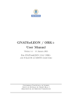
History
The term XtratuM derives from the word “stratum”. In geology and related fields it means:
Layer of rock or soil with internally consistent characteristics that distinguishes it from contiguous layers.
50
In order to stress the tight relation with Linux and the open source the “S” was replaced by “X”. XtratuM
would be the first layer of software (the one closer to the hardware), which provides a rock-solid basis
for the rest of the system.
First XtratuM version, proof-of-concept
Linux 2.4 [i386]
2004
0.01
2005
0.3
Second proof-of-concept
Linux 2.4 [i386]
2006
1.0
Code rewritten from scratch,
ported to Linux 2.6 [i386]
2007
2.0
Temporal & spatial isolation
Linux independent hypervisor [i386]
2008
2.1
2009
2.2
2010
3.1.0
2011
2.1.1
2.1.2
2.2.1
3.1.1
4.0
3.1.2
Highly Critical features added
(like ARINC-653) [Sparcv8]
2.2.2
3.2
Full featured highly
critical hypervisor
[Sparcv8, i386]
Highly Critical + MMU
2.2.4
Highly Critical + MMU + Multiprocessor
Linux module.
Only temporal isolation
Temporal & spatial
isolation
Ongoing
developments
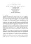
Figure 1.1: XtratuM evolution.
The first version of XtratuM (1.0) was initially developed to meet the requirements of a hard realtime system. The main goal of XtratuM 1.0 was to guarantee the temporal constrains for the real-time
partitions. Other characteristics of this version are:
Printed: November 26, 2012
xm-4-usermanual-047d
3/134
1.1. History
• The first partition shall be a modified version of Linux.
• Partition code has to be loaded dynamically.
55
• There is not a strong memory isolation between partitions.
• Linux is executed in processor supervisor mode.
• Linux is responsible of booting the computer.
• Fixed priority partition scheduling.
XtratuM 2.0 was a completely new redesign and implementation. This new version had nothing in
common with the first one but the name. It was truly a hypervisor with both, spatial and temporal
isolation. This version was developed for the x86 architecture but never released.
60
XtratuM 2.1 was the first porting to the LEON2 processor, and several safety critical features were
added. Just to mention the most relevant features:
• Bare-metal hypervisor.
65
• Employs para-virtualisation techniques.
• A hypervisor designed for embedded systems: some devices can be directly managed by a designated partition.
• Strong temporal isolation: fixed cyclic scheduler.
• Strong spatial isolation: all partitions are executed in the user mode of the processor, and do not
share memory.
70
• Resource allocation via a configuration table.
• Robust communication mechanisms (ARINC sampling and queuing ports).
Version 2.1 was a prototype to evaluate the capabilities of the LEON2 processor to support a hypervisor
system.
75
XtratuM 2.2 was a more mature hypervisor on the LEON2 processor. This version has most of the
final functionality.
XtratuM 3.1 introduces several changes. The main changes are:
• Audit events have been added as the XtratuM tracing subsistem.
• Virtual interrupt subsystem has been rewritten from scratch.
80
• Cache instruction burst fetch capability can be either enabled or disabled during the XtratuM
building process.
• Cache snoop feature can be either enabled or disabled during the XtratuM building process.
• Several partitions can be built with the same virtual addresses.
• Hypercalls behaviour is more robust.
85
XtratuM 3.2 introduces several changes. The main changes are:
• Any exception caused by a partition when the processor is in supervisor mode causes a partition
unrecoverable error.
xm-4-usermanual-047d
Printed: November 26, 2012
4/134
90
Chapter 1. Introduction
• A cache flush is executed always in order to guarantee that a partition is unable to retrieve XM
information. This operation is forced
XtratuM 3.5 is the developing version for XtratuM to LEON4 processor. It introduces important
changes with respect to monocore versions. Changes impact on most of the features. A summary
is
• XtratuM exports multiple virtual CPUS to the partitions
95
• Processor initialisation.
• Interrupt management
• Scheduling plan
• XML configuration file
When released it will be XtratuM 4.0.
Printed: November 26, 2012
xm-4-usermanual-047d
Volume 2: XtratuM User Manual
Chapter 2
XtratuM Architecture
This chapter introduces the architecture of XtratuM.
100
The concept of partitioned software architectures was developed to address security and safety issues.
The central design criteria involves isolating modules of the system into partitions. Temporal and
spatial isolation are the key aspects in a partitioned system. Based on this approach, the Integrated
Modular Avionics (IMA) is a solution allowed by the Aeronautic Industry to manage the increment of
the functionalities of the software maintaining the level of efficiency.
105
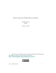
XtratuM is a bare-metal hypervisor designed to achieve temporal and spatial partitioning for safety
critical applications. Figure 2.1 shows the complete architecture.
Figure 2.1: XtratuM architecture.
The main components of this architecture are:
• Hypervisor: XtratuM provides virtualisation services to partitions. It is executed in supervisor
mode of the procesor and virtualises the CPU, memory, interrupts, and some specific peripherals.
The internal XtratuM architecture includes the following components:
110
– Memory management: XtratuM provides a memory model for the partitions enforcing the
spatial isolation. It uses the hardware mechanisms to guarantee the isolation.
– Scheduling: Partitions are scheduled by using a cyclic scheduling policy.
– Interrupt management: Interrupts are handled by XtratuM and, depending on the interrupt
nature, propagated to the partitions. XtratuM provides a interrupt model to the partitions
5/ 134
115
6/134
Chapter 2. XtratuM Architecture
that extends the concept of processor interrupts by adding 32 additional sources of interrupt
(events).
120
125
130
135
– Clock and timer management: XtratuM provides one global clock and one local clock to the
partitions. Partitions can set one timer for each clock.
– IP communication: Inter-partition communication is related to the communications between
two partitions or between a partition and the hypervisor. XtratuM implements a message
passing model which highly resembles the one defined in the ARINC-653. A communication channel is the logical path between one source and one or more destinations. Two
basic transfer modes are provided: sampling and queuing. Partitions can access to channels through access points named ports. The hypervisor is responsible for encapsulating and
transporting messages.
– Health monitor: The health monitor is the part of XtratuM that detects and reacts to anomalous events or states. The purpose of the HM is to discover the errors at an early stage
and try to solve or confine the faulting subsystem in order to avoid or reduce the possible
consequences.
– Tracing facilities: XtratuM provides a mechanism to store and retrieve the traces generated
by partitions and XtratuM itself. Traces can be used for debugging, during the development
phase of the application, but also to log relevant events or states during the production
phase.
• API: Defines the para-virtualised services provided by XtratuM. The access to these services is
provided through hypercalls.
140
145
• Partitions: A partition is an execution environment managed by the hypervisor which uses the
virtualised services. Each partition consists of one or more concurrent processes (concurrency
must be implemented by the operating system of each partition because it is not directly supported by XtratuM), that share access to processor resources based upon the requirements of
the application. The partition code can be: an application compiled to be executed on a baremachine; a real-time operating system (or runtime support) and its applications; or a general
purpose operating system and its applications.
Partitions need to be virtualised to be executed on top of a hypervisor. Depending on the type of
execution environment, the virtualisation implications in each case can be summarised as:
Bare application : The application has to be virtualised using the services provided by XtratuM. The
application is designed to run directly on the hardware so the the provided and non-provided
services of XtratuM must be taken into account.
150
155
Mono-core Operating system application : When the application runs on top of a (real-time) operating system, it uses the services provided by the operating system and does not need to be directly
virtualised. However, the operating system has to deal with the virtualisation and be virtualised
(ported on top of XtratuM).
Multi-core Operating system application : A guest OS can use multiple virtual CPU to support multicore applications
Printed: November 26, 2012
xm-4-usermanual-047d
7/134
2.1. Multicore architecture
2.1
Multicore architecture
This section introduces the multicore approach for XtratuM. The following notation is used:
CPU : It identifies the real CPUs in the hardware.
virtual CPU : It represents the virtualisation of the CPU provided by XtratuM to the partitions.
Partition : It corresponds to the execution environment where the application are executed. The
hypervisor offers a set of virtual CPUs that corresponds to the real CPUs are available in the
platform.
160
The goal of the hypervisor is to provide virtual CPUs to partitions in the same way that a multicore OS
see the CPUs if not virtualisation layer is present. From this point of view, the virtualisation layer will:
• Virtualise all the CPUs to the partitions offering them as virtual CPUs
165
• Initialise the execution of each CPU at the initialisation phase
• After the initialiation phase, start the execution of the plan 0.
• Initialise the virtual CPU identified as vcpu0 of each partition.
From the point of view of the partition:
• It can be mono or multicore.
170
• In monocore partitions, the vcpu0 is used.
– It is started by the hypervisor.
– The vcpu0 can be allocated by the integrator (XM CF configuration file) in any of the real
CPUs.
• In multicore partitions, only vcpu0 is initialised by the hypervisor.
175
– The vcpu0 code has to initialise the rest of virtual CPUs required.
– The virtual CPUs can be allocated by the integrator (XM CF configuration file) in any of the
real CPUs.
2.2
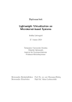
Architecture
Next figure 2.2 presents the approach in a monocore processor.
180
In the monocore architecture, XtratuM is in charge of the virtualisation of the CPU to the partitions.
A partition uses the virtual CPU to execute the internal code of the partition. The CPU is initialised by
the hypervisor and as soon as the system is initialised, the scheduling plan is started. The plan specifies
the sequence of slots to be executed. Each slot identifies a temporal window and the partition to be
executed.
185
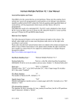
Figure 2.3 presents the approach in a multicore processor.
In the multicore architecture, XtratuM virtualises the available CPUs offering to the partitions virtual
CPUs. A partition can use one or more virtual CPUs to execute the internal code. Figure 2.4 shows an
example of how partitions can use one or more virtual CPUs to implement mono or multicore partitions.
xm-4-usermanual-047d
Printed: November 26, 2012
8/134
Chapter 2. XtratuM Architecture
Figure 2.2: Monocore approach.
Figure 2.3: Multicore approach.
190
In this case, one of the partition is monocore and only will use one of the virtual CPU available
(vCPU0). Others partitions are multicore and will use several virtual CPUs.
The system integrator is in charge of allocate the virtual CPUs to real CPUs in the configuration file.
Figure 2.5 shows an example of this allocation.
Printed: November 26, 2012
xm-4-usermanual-047d
9/134
2.2. Architecture
Figure 2.4: Example of mono and multi-core partitions.
Figure 2.5: vCPU/CPU allocation scheme.
xm-4-usermanual-047d
Printed: November 26, 2012
10/134
2.3
2.3.1
Chapter 2. XtratuM Architecture
System states and services
System states
The system’s states and its transitions are shown in figure 2.6.
Boot
XM_reset_system()
or
Hardware reset
Normal
Hardware
reset
XM_halt_system()
or
XM_HM_AC_HYPERVISOR_COLD_RESET
or
XM_HM_AC_HYPERVISOR_WARM_RESET
Halt
Figure 2.6: System’s states and transitions.
195
At boot time, the resident software loads the image of XtratuM in main memory and transfers control
to the entry point of XtratuM. The period of time between starting from the entry point, to the execution
of the first partition is defined as boot state. In this state, the scheduler is not enabled and the partitions
are not executed (see chapter 7).
200
205
210
At the end of the boot sequence, the hypervisor is ready to start executing partition code. The system
changes to normal state and the scheduling plan is started. Changing from boot to normal state is
performed automatically (the last action of the set up procedure).
The system can switch to halt state by the health monitoring system in response to a detected error
or by a system partition invoking the service XM halt system(). In the halt state: the scheduler is
disabled, the hardware interrupts are disabled, and the processor enters in an endless loop. The only
way to exit from this state is via an external hardware reset.
It is possible to perform a warm or cold (hardware reset) system reset by using the hypercall (see
XM reset system()). On a warm reset, the system increments the reset counter, and a reset value is
passed to the new rebooted system. On a cold reset, no information about the state of the system is
passed to the new rebooted system.
2.3.2
System states
Table 2.7 lists the system services.
Service
XM get system status
XM halt system
XM reset system
Description
Get the system status
Halt the system
Reset the system
Figure 2.7: System services
Printed: November 26, 2012
xm-4-usermanual-047d
11/134
2.4. Partition states and services
2.4
Partition states and services
2.4.1
Partition states
Once XtratuM is in normal state, partitions are started. The partition’s states and transitions are shown
in figure 2.8.
XM_HM_AC_PARTITION_COLD_RESET
or
XM_HM_AC_PARTITION_WARM_RESET
or
XM_reset_partition()
Boot
XM_resume_partition()
Normal
- ready
- running
- idle
Suspend
XM_halt_partition()
or
XM_HM_AC_HALT
Halt
XM_suspend_partition()
or
XM_HM_AC_SUSPEND
Figure 2.8: Partition states and transitions.
215
On start-up each partition is in boot state. It has to prepare the virtual machine to be able to run
the applications1 : it sets up a standard execution environment (that is, initialises a correct stack and
sets up the virtual processor control registers), creates the communication ports, requests the hardware
devices (I/O ports and interrupt lines), etc., that it will use. Once the partition has been initialised, it
changes to normal mode.
220
The partition receives information from XtratuM about the previous executions, if any.
From the hypervisor point of view, there is no difference between the boot state and the normal state.
In both states the partition is scheduled according to the fixed plan, and has the same capabilities.
Although not mandatory, it is recommended that the partition emits a partition’s state-change event
when changing from boot to normal state.
225
The normal state is subdivided in three sub-states:
Ready The partition is ready to execute code, but it is not scheduled because it is not in its time slot.
Running The partition is being executed by the processor.
Idle If the partition does not want to use the processor during its allocated time slot, it can relinquish
the processor, and wait for an interrupt or for the next time slot (see XM idle self()).
A partition can halt itself or be halted by a system partition. In the halt state, the partition is not selected by the scheduler and the time slot allocated to it is left idle (it is not allocated to other partitions).
1 We
will consider that the partition code is composed of an operating system and a set of applications.
xm-4-usermanual-047d
Printed: November 26, 2012
230
12/134
Chapter 2. XtratuM Architecture
All resources allocated to the partition are released. It is not possible to return to normal state.
235
In suspended state, a partition will not be scheduled and interrupts are not delivered. Interrupts
raised while in suspended state are left pending. If the partition returns to normal state, then pending
interrupts are delivered to the partition. The partition can return to ready state if requested by a system
partition by calling XM resume partition() hypercall.
2.4.2
Partition services
Table 2.9 lists the partition services.
Service
XM get partition status
XM halt partition
XM reset partition
XM resume partition
XM shutdown partition
XM suspend partition
Description
Get the status of the partition
Halt the partition
Reset the partition
Resume the partition
Shutdown the partition
Suspend the partition
Figure 2.9: Partition services
2.5 Virtual CPU states and operation
240
245
From the CPU point of view, XtratuM mimics the behaviour of a multicore system. When the system is
booted, CPU0 is started and is the software (operating systems) the responsible of start the execution
of the rest of CPUs.
XtratuM offers the same behaviour to partition for the virtual CPU. When booted each partition, they
have vCPU0 running and it is responsability of each partition to start the execution of others virtual
CPU’s if required.
virtual CPU’s are internal abstractions to each partition. virtual CPU’s only can be seen and handled
by its partition. A partition can not access to any service related to virtual CPU’s of other partition.
virtual CPU’s, as partitions, are controlled through a set of services that change its status. The virtual
CPU’s states and transitions are shown in figure 2.10.
250
255
On start-up each virtual CPU is in boot state. It has to prepare the virtual CPUs to be able to run
the applications: it sets up a standard execution environment (that is, initialises a correct stack and
sets up each virtual CPU control registers), creates the communication ports, requests the hardware
devices (I/O ports and interrupt lines), etc., that it will use. Once the virtual CPU has been initialised,
it changes to normal mode.
From the hypervisor point of view, there is no difference between the boot state and the normal state.
In both states the virtual CPUs are scheduled according to the fixed plan, and has the same capabilities.
The normal state is subdivided in three sub-states:
Ready The virtual CPU is ready to execute code, but it is not scheduled because it is not in its time slot.
260
Running The virtual CPU of the partition is being executed by the processor where the virtual CPU is
allocated.
Idle If the virtual CPU does not want to use the processor during its allocated time slot, it can relinquish
the processor, and wait for an interrupt or for the next time slot (see XM idle self()).
Printed: November 26, 2012
xm-4-usermanual-047d
13/134
2.6. System partitions
Figure 2.10: Virtual CPU states and transitions.
A virtual CPU can halt itself or be halted by another vCPU of the same partition. When halted, the
virtual CPU is not selected by the scheduler and the time slot allocated to it is left idle (it is not allocated
to other partitions). All resources allocated to the virtual CPU are released. It is not possible to return
to normal state.
265
In suspended state, the virtual CPU is not be scheduled and interrupts are not delivered. Interrupts
raised while in suspended state are left pending. The virtual CPU can return to ready state if requested
by another vCPU of the the partition by calling XM resume vcpu() hypercall.
The state of the virtual CPU’s of a partition depends on the partition state. When a partition management service is invoked to a target partition, the following effects are produced:
270
Partition reset All virtual CPU’s of the partition are halted. The partition restarts with the vCPU0.
Partition suspend All virtual CPU’s of the partition in normal state are suspended.
Partition resume All virtual CPU’s of the partition, as they were when the partition was suspended,
are restored.
275
Partition halt All virtual CPU’s of the partition are halted.
2.5.1 virtual CPU services
Table 2.1 lists the virtual CPU services.
2.6
System partitions
XtratuM defines two types of partitions: normal and system. System partitions are allowed to manage
and monitor the state of the system and other partitions. Some hypercalls only can be invoked from
xm-4-usermanual-047d
Printed: November 26, 2012
280
14/134
Chapter 2. XtratuM Architecture
Service
XM get vcpuid
XM halt vcpu
XM reset vcpu
XM resume vcpu
XM suspend vcpu
Description
Get the vCPU identifier
Halt the vCPU
Reset the vCPU
Resume the vCPU
Suspend the vCPU
Table 2.1: CPU services
a system partition or, more properly, these hypercall only can succeed when are invoked from system
partition. Normal partitions requesting these services get a permission error as response.
285
290
It is important to point out that system partition rights are related to the capability to manage the
system, and not to the capability to access directly to the native hardware or to break the isolation: a
system partition is scheduled as a normal partition; and it can only use the resources allocated to it in
the configuration file.
Table 2.2 shows the list of hypercalls reserved for system partitions. A hypercall labeled as “partial”
indicates that a normal partition can invoke it if a system reserved service is not requested. For instance,
a normal partition can invoke the service XM halt partition if the target partition is itself. To use this
service with another partition, the invoking partition has to be defined as system partition.
Hypercall
XM
XM
XM
XM
XM
XM
XM
XM
XM
XM
XM
XM
XM
XM
XM
XM
XM
XM
XM
XM
get gid by name
get partition status
get system status
halt partition
halt system
hm open
hm read
hm seek
hm status
memory copy
reset partition
reset system
resume partition
shutdown partition
suspend partition
switch sched plan
trace open
trace read
trace seek
trace status
System
Partial
Partial
Yes
Partial
Yes
Yes
Yes
Yes
Yes
Partial
Partial
Yes
Yes
Partial
Partial
Yes
Yes
Yes
Yes
Yes
Table 2.2: List of system reserved hypercalls.
A partition has system capabilities if the /System Description/Partition Table/Partition/@flags
attribute contains the flag “system” in the XML configuration file. Several partitions can be defined as
system partition.
Printed: November 26, 2012
xm-4-usermanual-047d
15/134
2.7. Names and identifiers
2.7
Names and identifiers
Each partition is globally identified by a unique identifier id. Partition identifiers are assigned by the
integrator in the XM CF file. XtratuM uses this identifier to refer to partitions. System partitions use
partition identifiers to refer to the target partition. The “C” macro XM PARTITION SELF can be used by
a partition to refer to itself.
These ids are used internally as indexes to the corresponding data structures2 . The fist “id” of each
object group shall start in zero and the next id’s shall be consecutive. It is mandatory to follow this
order in the XM CF file.
295
300
The attribute name of a partition is a human readable string. This string shall contain only the
following set of characters: upper and lower case letters, numbers and the underscore symbol. It is
advisable not to use the same name on different partitions. A system partition can get the name of
another partition by consulting the status object of the target partition.
In order to avoid name collisions, all the hypercalls of XtratuM contain the prefix “XM”. Therefore, the
prefix “XM”, both in upper and lower case, is reserved.
305
2.7.1 Virtual CPU identifiers
Each virtual CPU in each partition is locally identified by a unique identifier vcpuId. Each virtual CPU
can identify itself by the symbol XM VCPU SELF.
These vcpuIds are used internally as indexes to the corresponding data structures.
2.8
310
Partition scheduling
XtratuM schedules partitions in a fixed, cyclic basis (ARINC-653 scheduling policy). This policy ensures
that one partition cannot use the processor for longer than scheduled to the detriment of the other
partitions. The set of time slots allocated to each partition is defined in the XM CF configuration file
during the design phase. Each partition is scheduled for a time slot defined as a start time and a
duration. Within a time slot, XtratuM allocates the processor to the partition.
315
If there are several concurrent activities in the partition, the partition shall implement its own scheduling algorithm. This two-level scheduling scheme is known as hierarchical scheduling. XtratuM is not
aware of the scheduling policy used internally on each partition.
In general, a cyclic plan consists of a major time frame (MAF) which is periodically repeated. The
MAF is typically defined as the least common multiple of the periods of the partitions (or the periods
of the threads of each partition, if any).
For instance, consider the partition set of figure 2.3a, its hyper-period is 200 time units (milliseconds)
and has a CPU utilisation of the 90%. The execution chronogram is depicted in figure 2.11. One of the
possible cyclic scheduling plans can be described, in terms of start time and duration, as it is shown in
the table 2.3b.
320
325
This plan has to be specified in the configuration file. An XML file describing this schedule is shown
below.
<Processor id="0" frequency="50Mhz">
<CyclicPlanTable>
<Plan id="0" majorFrame="200ms">
<Slot id="0" start="0ms" duration="20ms" partitionId="0 />
<Slot id="1" start="20ms" duration="10ms" partitionId=1/>
2 For
efficiency and simplicity reasons.
xm-4-usermanual-047d
Printed: November 26, 2012
330
16/134
Chapter 2. XtratuM Architecture
Partition 1
Partition 2
Partition 3
Partition 4
Partition 5
Name
System Mngmt
Flight Control
Flight Mngmt
IO Processing
IHVM
Period
100
100
100
100
200
WCET
20
10
30
20
20
Util. %
20
10
30
20
10
(a) Partition set.
Start
0
20
40
30
180
Partition 0
Partition 1
Partition 2
Partition 3
Partition 4
Dur.
20
10
30
10
20
Start
100
120
140
70
Dur.
20
10
30
10
Start
Dur.
Start
Dur.
130
10
170
10
(b) Detailed execution plan.
Table 2.3: Partition definition.
<Slot id="2" start="30ms" duration="10ms" partitionId="3 />
<Slot id="3" start="40ms" duration="30ms" partitionId=2 />
<Slot id="4" start="70ms" duration="10ms" partitionId="3 />
335
<Slot id="5" start="100ms" duration="20ms" partitionId="0 />
<Slot id="6" start="120ms" duration="10ms" partitionId=1/>
<Slot id="7" start="130ms" duration="10ms" partitionId="3 />
<Slot id="8" start="140ms" duration="30ms" partitionId=2 />
<Slot id="9" start="170ms" duration="10ms" partitionId=3 />
<Slot id="10" start="180ms" duration="20ms" partitionId=4/>
</Plan>
</CyclicPlanTable>
</Processor>
</Processor>
340
345
Hypervisor
P5
P4
P3
P2
P1
Idle
0
10
20
30
40
50
60
70
80
90
100
110
120
130
140
150
160
170
180
190
200
Figure 2.11: Scheduling example.
350
One important aspect in the design of the XtratuM hypervisor scheduler is the consideration of the
overhead caused by the partition’s context switch. In the document “XtratuM Scheduling analysis” it
is provided a deep analysis of the scheduling aspects related to the partition context switch and its
implications.
2.8.1
Multiple scheduling plans
In some cases, a single scheduling plan may be too restrictive. For example:
• Depending on the guest operating system, the initialisation can require a certain amount of time
Printed: November 26, 2012
xm-4-usermanual-047d
17/134
2.8. Partition scheduling
and can vary significantly. If there is a single plan, the initialisation of each partition can require
a different number of slots due to the fact that the slot duration has been designed considering
the operational mode. This implies that a partition can be executing operational work whereas
others are still initialising its data.
• The system can require to execute some maintenance operations. These operation can require
allocating other resources different from the ones required during the operational mode.
355
360
In order to deal with these issues, XtratuM provides multiple scheduling plans that allows to reallocate
the timing resources (the processor) in a controlled way. In the scheduling theory this process is known
as mode changes. Figure 2.12 shows how the modes have been considered in the XtratuM scheduling.
Boot
Halt
Normal
Maintenance
plan
Plan 1
Plan 0
Initial
plan
Plan 2
Plan N
Figure 2.12: Scheduling modes.
The scheduler (and so, the plans) is only active while the system is in normal mode. Plans are defined
in the XM CF file and identified by a identifier. Some plans are reserved or have a special meaning:
365
Plan 0: Initial plan. The system selects this plan after a system reset. The system will be in plan 0 until
a plan change is requested.
It is not legal to switch back to this plan. That is, this plan is only executed as a consequence of a
system reset (software or hardware).
Plan 1: Maintenance plan. This plan can be activated in two ways:
370
• As a result of the health monitoring action XM HM AC SWITCH TO MAINTENANCE. The plan
switch is done immediately.
• Requested from a system partition. The plan switch occurs at the end the current plan.
It is advisable to allocate the first slot of this plan to a system partition, in order to start the maintenance activity as soon as possible after the plan switch. Once the maintenance activities have
been completed, it is responsibility of a system partition to switch to another plan (if needed).
A system partition can also request a switch to this.
Plan x (x>1): Any plan greater than 1 is user defined. A system partition can switch to any of these
defined plan at any time.
xm-4-usermanual-047d
Printed: November 26, 2012
375
18/134
2.8.2
380
Chapter 2. XtratuM Architecture
Switching scheduling plans
When a plan switch is requested by a system partition (through a hypercall), the plan switch is not
immediate; all the slots of the current plan will be completed, and the new plan will be started at the
end of the current one.
The plan switch that occurs as a consequence of the XM HM AC SWITCH TO MAINTENANCE action is synchronous. The current slot is terminated, and the Plan 1 is started immediately.
2.9
385
In this section, the scheduling policies implemented and how they are specified in the configuration file
are described,
2.9.1
390
XtratuM Multicore Scheduling
Scheduling units
The scheduling unit is a virtual CPU of a partition. By default, if the virtual CPU is not specified, it is
assumed that it refers to the vCPU0 (vcpuId = 0). In general, we refer to this unit as a pair represented
as < partition, vcpu >.
2.9.2
Scheduling policies
XtratuM provides different policies that can be attached to any of the CPU. Two basic policies are
defined:
395
400
405
Cyclic scheduling : Pairs < partition, vcpu > are scheduled in a fixed, cyclic basis (ARINC-653
scheduling policy). This policy ensures that one partition cannot use the processor for longer
than scheduled to the detriment of the other partitions. The set of time slots allocated to each
< partition, vcpu > is defined in the XM CF configuration file. Each < partition, vcpu > is scheduled for a time slot defined as a start time and a duration. Within a time slot, XtratuM allocate
the system resources to the partition and virtual CPU specified.
Priority scheduling : Under this scheduling policy, pairs < partition, vcpu > are scheduled based
on the partition priority. The partition priority is specified in the configuration file. Priority 0
corresponds to the highest priority. All pairs < partition, vcpu > in normal state (ready) allocated
in the configuration file to a processor attached to this policy are executed taking into account its
priority.
2.9.3
Cyclic scheduling
In general, a cyclic plan consists of a major time frame (MAF) which is periodically repeated. The MAF
is typically defined as the least common multiple of the periods of the partitions (or the periods of the
threads of each partition, if any).
410
415
This plan has to be specified in the configuration file. An XML file describing this schedule is shown
below.
<Processor id="0" frequency="50Mhz">
<CyclicPlanTable>
<Plan id="0" majorFrame="800ms">
<Slot id="0" start="0ms" duration="200ms" partitionId="0 vCpuId="0"/>
Printed: November 26, 2012
xm-4-usermanual-047d
19/134
2.9. XtratuM Multicore Scheduling
<Slot id="1" start="200ms" duration="200ms" partitionId=2 vCpuId="0"/>
<Slot id="2" start="400ms" duration="200ms" partitionId="0 vCpuId="1"/>
<Slot id="3" start="600ms" duration="200ms" partitionId=1 vCpuId="0"/>
</Plan>
</CyclicPlanTable>
</Processor>
<Processor id="1" frequency="50Mhz">
<CyclicPlanTable>
<Plan id="0" majorFrame="800ms">
<Slot id="0" start="0ms" duration=300ms" partitionId= 3 vCpuId="0"/>
<Slot id="1" start=300ms" duration="200ms" partitionId= 0 vCpuId= 2 "/>
<Slot id="1" start=500ms" duration="200ms" partitionId= 2 vCpuId= 1 "/>
</Plan>
</CyclicPlanTable>
</Processor>
420
425
430
This plan produces a scheduling as detailed in the next figure 2.13.
Figure 2.13: Cyclic plan example.
In this scheduling plan, the configuration file defines:
• partition P0 allocates its vCPU0 and vCPU1 in CPU0 and VCPU2 in CPU1.
• partition P1 allocates its vCPU0 in CPU0
435
• partition P2 allocates its vCPU0 in CPU0 and vCPU1 in CPU1
• partition P3 allocates its vCPU0 in CPU1
2.9.4
Fixed priority scheduling
The priority based policy selects between the ready VCPUs allocated to the core, the VCPU with a
highest priority. This scheduling policy is preemptive allowing to switch to a higher priority VCPU at
any time.
440
The definition of the CPUs under the priority based scheduling policy and they allocation of pairs
< partition, vcpu > to it has to be specified in the configuration file. A XML file describing this schedule
is shown below.
445
<Processor id="2" frequency="50Mhz">
<FixedPriority>
<Partition id="0" vCpuId=3" priority="10"/>
<Partition id="1" vCpuId="1" priority="5"/>
</FixedPriority>
</Processor>
450
In this example, the CPU2 is defined to be scheduled under the priority based scheduling policy. Pairs
< P 0, vCP U 3 > and < P 1, vCP U 1 > are allocated to this processor and, as consequence, to this
policy. to this policy independently of the plan.
xm-4-usermanual-047d
Printed: November 26, 2012
455
20/134
Chapter 2. XtratuM Architecture
Note that if the scheduling policy of a CPU is defined as fixed priority, this CPU is not affected by the
the cyclic plans of other CPUs.
In the multicore approach, the following aspects have to be taken into account:
• Only cyclic plans are associated to the multiple plans.
460
• If a processor is defined under a priority based policy, the policy applies independently of the
plan.
• Plans involving several processors have to define the same Major Frame (MAF).
An example of the scheduling definition is listed below.
465
470
475
480
485
490
495
500
505
510
<ProcessorTable>
<Processor id="0" frequency="50Mhz">
<CyclicPlanTable>
<Plan id="0" majorFrame="1s">
<Slot id="0" start="0ms" duration="500ms" partitionId
="0" vCpuId="0"/>
<Slot id="1" start="500ms" duration="500ms"
partitionId="1" vCpuId="0"/>
</Plan>
<Plan id="1" majorFrame="600ms">
<Slot id="0" start="0ms" duration="410ms" partitionId
="0" vCpuId="0"/>
<Slot id="1" start="450ms" duration="150ms"
partitionId="1" vCpuId="0"/>
</Plan>
</CyclicPlanTable>
</Processor>
<Processor id="1" frequency="50Mhz">
<CyclicPlanTable>
<Plan id="0" majorFrame="1s">
<Slot id="0" start="0ms" duration="500ms" partitionId
="2" vCpuId="0"/>
<Slot id="0" start="500ms" duration="500ms"
partitionId="3" vCpuId="0"/>
</Plan>
<Plan id="1" majorFrame="600ms">
<Slot id="0" start="0ms" duration="400ms" partitionId
="2" vCpuId="0"/>
<Slot id="1" start="400ms" duration="200ms"
partitionId="3" vCpuId="0"/>
</Plan>
</CyclicPlanTable>
</Processor>
<Processor id="2" frequency="50Mhz">
<CyclicPlanTable>
<Plan id="1" majorFrame="600ms">
<Slot id="0" start="0ms" duration="200ms" partitionId
="0" vCpuId="1"/>
<Slot id="1" start="200ms" duration="360ms"
partitionId="2" vCpuId="1"/>
</Plan>
</CyclicPlanTable>
</Processor>
<Processor id="3" frequency="50Mhz">
<FixedPriority>
Printed: November 26, 2012
xm-4-usermanual-047d
21/134
2.9. XtratuM Multicore Scheduling
<Partition id="0" vCpuId=2" priority="10"/>
<Partition id="1" vCpuId="1" priority="5"/>
</FixedPriority>
</Processor>
</ProcessorTable>
xm-4-usermanual-047d
Printed: November 26, 2012
515
22/134
2.10
Chapter 2. XtratuM Architecture
Memory management
Partitions and XtratuM core can be allocated at defined memory areas specified in the XM CF.
520
A partition define several memory areas. Each memory area can define some attributes or rights
to permit to other partitions to access to their defined areas or allow the cache management. The
following attributes area allowed:
unmapped Allocated to the partition, but not mapped by XtratuM in the page table.
mappedAt It allows to allocate this area to a virtual address.
shared It is allowed to map this area in other partitions.
read-only The area is write-protected to the partition.
525
uncacheable Memory cache is disabled.
The implementation of the whole set of features will depend on the available hardware. For systems
with a MMU (Memory Management Unit), most (or all of them) will be available, though in systems
with MPU (Memory Protection Unit) or WPR (Write Protection Registers) most of the may not be. See
section 5.16 for more details.
Printed: November 26, 2012
xm-4-usermanual-047d
23/134
2.11. IO-MMU support
2.11
IO-MMU support
530
LEON4 processor implements an io-mmu in order to enable logic partitioning of io resources: any
partition access to IO resources is translated through the mmu, allowing an effective spatial isolation.
Nevertheless, since DMA accesses were not translated, its use permitted to break spatial isolation: a
partition could program a DMA transference overwriting or retrieving the content of area belonging to
another partition or the hypervisor.
The io-mmu is a mmu interposed between master AHB devices and slaves ones, enabling an effective
real spatial isolation. XtratuM allows to the system integrator to make use of the io-mmu through the
xml configuration file. More concretely, the element /SystemDescription/Hypervisor/IoMmu permits
to define a table in order to link one or a set of AHB master buses to a partition. A maximum of 6 of
such links are allowed (restriction imposed by the LEON4 implementation). Additionally, the system
integrator must define the bus to use for accesses by the AHB master (@busRouting) which can be
either processor or memory and the vendor and device PNP Id of the master.
535
540
Eventually, in order to avoid huge io-memory tables, XtratuM implements:
• The lowest possible ITR (area protected size). Taken into account that the upper part shall start
in 0xffffffff (restriction imposed by LEON4).
545
• The largest page size which better fits with the partition’s area sizes.
• A new possible flag iommu has been added to PhysicalMemoryAreas/Area/@flags in order to
indicate that only the areas with this new flags shall be mapped in the io-mmu.
Following is an example of use of the io-mmu with two partitions:
550
<?xml version="1.0"?>
<SystemDescription xmlns="http://www.xtratum.org/xm-3.x" version="1.0.0"
name="Example_iommu">
<HwDescription>
<ProcessorTable>
<Processor id="0" frequency="50Mhz">
<Sched>
<CyclicPlan>
<Plan id="0" majorFrame="500ms">
<Slot id="0" start="0ms" duration="250ms" partitionId="0"/>
<Slot id="1" start="250ms" duration="250ms" partitionId="1"/>
</Plan>
</CyclicPlan>
</Sched>
</Processor>
</ProcessorTable>
<Devices>
<Uart id="0" baudRate="115200" name="Uart"/>
</Devices>
<MemoryLayout>
<Region type="stram" start="0x0" size="32MB"/>
<Region type="rom" start="0x80000000" size="32MB" />
</MemoryLayout>
</HwDescription>
<XMHypervisor console="Uart">
<PhysicalMemoryAreas>
<Area start="0x40000000" size="512KB" flags="uncacheable"/>
</PhysicalMemoryAreas>
xm-4-usermanual-047d
Printed: November 26, 2012
555
560
565
570
575
24/134
580
585
590
595
600
605
Chapter 2. XtratuM Architecture
<IoMmu>
<AhbMst id="0" partitionId="1" busRouting="processor" vendorId="0x1
" deviceId="0x20" />
<AhbMst id="1" partitionId="0" busRouting="memory" vendorId="0x1"
deviceId="0x20" />
<AhbMst id="2" partitionId="0" busRouting="memory" vendorId="0x1"
deviceId="0x20" />
</IoMmu>
</XMHypervisor>
<PartitionTable>
<Partition id="0" name="Partition1" flags="" console="Uart">
<PhysicalMemoryAreas>
<Area start="0x300000" size="512KB"/>
<Area start="0x80000000" size="4KB" flags="iommu"/>
</PhysicalMemoryAreas>
<TemporalRequirements duration="500ms" period="500ms"/>
</Partition>
<Partition id="1" name="Partition2" flags="system" console="Uart">
<PhysicalMemoryAreas>
<Area start="0x500000" size="512KB" flags="uncacheable"/>
<Area start="0x80001000" mappedAt="0xff000000" size="512KB" flags="
uncacheable iommu"/>
</PhysicalMemoryAreas>
</Partition>
</PartitionTable>
</SystemDescription>
Listing 2.1: XML example
610
In the example, two master buses (AHB1 and AHB2) use an io-mmu table having access to the area
[0x80000000 - 0x80000fff] (area defined by the partition 0) and the bus AHB0 which has been allocated to the partition 1, uses a table which translates any access to the area [0xff000000 - 0xff070000]
to [0x80001000 - 0x8008ffff]. In this example, the ITR is 7, the page size is 4KB and there will be two
tables of 2 MBytes each one.
Printed: November 26, 2012
xm-4-usermanual-047d
2.12. Inter-partition communications (IPC)
2.12
25/134
Inter-partition communications (IPC)
Inter-partition communications are communications between two partitions. XtratuM implements a
message passing model which highly resembles the one defined in the ARINC-653 standard. A message
is a variable3 block of data. A message is sent from a source partition to one or more destination
partitions. The data of a message is transparent to the message passing system.
A communication channel is the logical path between one source and one or more destinations.
Partitions can access to channels through access points named ports. The hypervisor is responsible for
encapsulating and transporting messages that have to arrive to the destination(s) unchanged.
At the partition level, messages are atomic entities i.e., either the whole message is received or nothing
is received. Partition developers are responsible for agreeing on the format (data types, endianess,
padding, etc.).
615
620
Channels, ports, maximum message sizes and maximum number of messages (queuing ports) are
entirely defined in the configuration files (see section 8).
XtratuM provides two basic transfer modes: sampling and queuing.
Sampling port: It provides support for broadcast, multicast and unicast messages. No queuing is
supported in this mode. A message remains in the source port until it is transmitted through the
channel or it is overwritten by a new occurrence of the message, whatever occurs first. Each new
instance of a message overwrites the current message when it reaches a destination port, and
remains there until it is overwritten. This allows the destination partitions to access the latest
message.
A partition’s write operation on a specified port is supported by XM write sampling message()
hypercall. This hypercall copies the message into an internal XtratuM buffer. Partitions can read
the message by using XM read sampling message() which returns the last message written in the
buffer. XtratuM copies the message to the partition space.
Any operation on a sampling port is non-blocking: a source partition can always write into the
buffer and the destination partition/s can read the last written message.
625
630
635
The channel has an optional configuration attribute named @refreshPeriod. This attribute defines the maximum time that the data written in the channel is considered “valid”. Messages older
than the valid period are marked as invalid. When a message is read, a bit is set accordingly to
the valid state of the message.
Queuing port: It provides support for buffered unicast communication between partitions. Each port
has associated a queue where messages are buffered until they are delivered to the destination
partition. Messages are delivered in FIFO order.
Sending and receiving messages are performed by two hypercalls: XM send queuing message()
and XM receive queuing message(), respectively. XtratuM implements a classical producerconsumer circular buffer without blocking. The sending operation writes the message from partition space into the circular buffer and the receive one performs a copy from the XtratuM circular
buffer into the destination memory.
If the requested operation cannot be completed because the buffer is full (when trying to send
a message) or empty (when attempting to receive a message), then the operation returns immediately with the corresponding error. The partition’s code is responsible for retrying the
operation later.
Queuing ports can specify a policy FIFO or PRIORITY for the source or destination. XtratuM does
not handle this attribute but provides the attribute to the partitions in order to be handled by the
guest operating system to wake blocked threads in write or read operations on the port under any
of these disciplines.
3 XtratuM
defines the maximum length of a message.
xm-4-usermanual-047d
Printed: November 26, 2012
640
645
650
655
26/134
660
Chapter 2. XtratuM Architecture
In order to optimise partition’s resources and reduce the performance loss caused by polling the state
of the port, XtratuM triggers an extended interrupt when a new message is written/sent to a port. Since
there is only one single interrupt line to notify for incoming messages, on the reception of the interrupt,
the partition code has to determine which port or ports are ready to perform the operation. XtratuM
maintains a bitmap in the Partition Control Table to inform about the state of each port. A “1” in the
corresponding entry indicates that the requested operation can be performed.
When a new message is available in the channel, XtratuM triggers an extended interrupt to the destination(s).
2.12.1
665
670
675
680
685
Multicore implications
When the plan allocates partitions in several CPU’s, partitions involved in a communication can be
running or not at the same time. If they do not overlap in time, the reader will receive the interrupt at
the begining of its slot. If they overlap, as soon as the writer partition sends the message, XtratuM will
deliver the interrupt the reader partition that will be able to receive the message.
In order to implement the notification of the message, a set of interrupts have been added. List below
shos these interrupts.
* Inter-Partition Virtual Interrupts */
#define XM_MAX_IPVI CONFIG_XM_MAX_IPVI
#define XM_VT_EXT_IPVI0 (24+XM_VT_EXT_FIRST)
#define XM_VT_EXT_IPVI1 (25+XM_VT_EXT_FIRST)
#define XM_VT_EXT_IPVI2 (26+XM_VT_EXT_FIRST)
#define XM_VT_EXT_IPVI3 (27+XM_VT_EXT_FIRST)
#define XM_VT_EXT_IPVI4 (28+XM_VT_EXT_FIRST)
#define XM_VT_EXT_IPVI5 (29+XM_VT_EXT_FIRST)
#define XM_VT_EXT_IPVI6 (30+XM_VT_EXT_FIRST)
#define XM_VT_EXT_IPVI7 (31+XM_VT_EXT_FIRST)
XtratuM implements a homogeneous policy for access, on a per-partition basis, to the resources. It
implies that the internal subjects (VCPUs or threads) in a partition have the same requirements for
access to the resources specified in the configuration file.
Is responsability of the guest OS to define another policy. For instance, a guest OS could define a
Least Provilege Abstraction which assumes that the internal subjects (VCPU or threads) in a partition
have heterogeneous requirements for access to the resources. In this case, the guest OS could restrict
the defined operations to some internal subjects.
2.13
690
695
700
Health monitor (HM)
The health monitor is the part of XtratuM that detects and reacts to anomalous events or states. The
purpose of the HM is to discover the errors at an early stage and try to solve or confine the faulting
subsystem in order to avoid a failure or reduce the possible consequences.
It is important to clearly understand the difference between 1) an incorrect operation (instruction,
function, application, peripheral, etc.) which is handled by the normal control flow of the software,
and 2) an incorrect behaviour which affects the normal flow of control in a way not considered by the
developer or which can not be handled in the current scope.
An example of the first kind of errors is: the malloc() function returns a null pointer because there is
not memory enough to attend the request. This error is typically handled by the program by checking
the return value. As for the second kind, an attempt to execute an undefined instruction (processor
instruction)may not be properly handled by a program that attempted to execute it.
Printed: November 26, 2012
xm-4-usermanual-047d
27/134
2.13. Health monitor (HM)
The XtratuM health monitoring system will manage those faults that cannot, or should not, be managed at the scope where the fault occurs.
The XtratuM HM system is composed of four logical blocks:
HM event detection:
to detect abnormal states, using logical probes in the XtratuM code.
705
HM actions:
a set of predefined actions to recover a fault or confine an error.
HM configuration:
to bind the occurence of each HM event with the appropriate HM action.
HM notification:
to report the occurrence of the HM events.
710
Since HM events are, by definition, the result of a unexpected behaviour of the system, it may be
difficult to clearly determine which is the original cause of the fault, and so, what is the best way to
handle the problem. XtratuM provides a set of “coarse grain” actions (see section 2.13.2) that can be
used at the first stage, right when the fault is detected. Although XtratuM implements a default action
for each HM event, the integrator can map an HM action to each HM event using the XML configuration
file.
Once the defined HM action is carried out by XtratuM, a HM notification message is stored in the HM
log stream (if the HM event is marked to generate a log). A system partition can then read those log
messages and perform a more advanced error handling. As an example of what can be implemented:
715
720
1. Configure the HM action to stop the faulting partition, and log the event.
2. The system partition can resume an alternate one, a redundant dormant partition, which can be
implemented by another developer team to achieve diversity.
Since the differences between fault4 and error5 are so subtle and subjective, we will use both terms to
refer to the original reason of an incorrect state.
725
The XtratuM health monitoring subsystem defines four different execution scopes, depending on
which part of the system has been initially affected:
1. Process scope: Partition process or thread.
2. Partition scope: Partition operating system or run-time support.
3. Hypervisor scope: XtratuM code.
730
4. Board scope: Resident software (BIOS, BOOT ROM or firmware).
The scope6 where an HM event should be managed has to be greater than the scope where it is
“believed” it can be produced.
There is not a clear and unique scope for each HM event. Therefore the same HM event may be
handled at different scopes. For example, fetching an illegal instruction is considered hypervisor scope
if it happens when while XtratuM is executing; and partition level if the event is raised while a partition
is running.
XtratuM tries to determine the most likely scope target, and to deliver the HM to the corresponding
upper scope.
4 Fault:
What is believed to be the original reason that caused an error.
The manifestation of a fault.
6 The term level is used in the ARINC-653 standard to refer to this idea
5 Error:
xm-4-usermanual-047d
Printed: November 26, 2012
735
28/134
Chapter 2. XtratuM Architecture
Monitoring
Partition
XM_hm_open()
XM_hm_read()
XM_hm_seek()
HM
log message
XML
configuration
HM
subsystem
HM
actions
HM
events
fault
XtratuM
HM log
stream
error
failure
fault
error
failure
fault
error
failure
Figure 2.14: Health monitoring overview.
2.13.1
740
HM Events
There are three sources of HM events:
• Events caused by abnormal hardware behaviour. Most of the processor exceptions are managed
as health monitoring events.
745
• Events detected and triggered by partition code. These events are usually related to checks or
assertions on the code of the partitions. Health monitoring events raised by partitions are
a special type of tracing message (see sections 2.16). Highly critical tracing messages are
considered as HM events.
• Events triggered by XtratuM. Caused by a violation of a sanity check performed by XtratuM on its
internal state or the state of a partition.
750
When a HM event is detected, the relevant information (error scope, offending partition identifier,
memory address, faulting device, etc.) is gathered and used to select the apropiate HM action.
The next table shows the event detected by XtratuM:
Printed: November 26, 2012
xm-4-usermanual-047d
29/134
2.13. Health monitor (HM)
Action
XM
XM
XM
XM
XM
HM
HM
HM
HM
HM
Description
EV
EV
EV
EV
EV
INTERNAL ERROR
UNEXPECTED TRAP
PARTITION UNRECOVERABLE
PARTITION ERROR
PARTITION INTEGRITY
XM HM EV MEM PROTECTION
XM
XM
XM
XM
XM
XM
HM
HM
HM
HM
HM
HM
EV
EV
EV
EV
EV
EV
OVERRUN
SCHED ERROR
WATCHDOG TIMER
INCOMPATIBLE INTERFACE
ARM UNDEF INSTR
ARM PREFETCH ABORT
XM HM EV ARM DATA ABORT
2.13.2
Internal XtratuM error.
XtratuM detected a mismatch between the partition’s digest stored in the container and the one calculated from
the partition’s section inside the container.
Either XtratuM or a partition triggered a memory protection error.
The processor received a watchdog timer signal.
The processor detected an unknown instruction.
An instruction prefetching error was encountered according to the conditions described in the ARM architecture
manual.
A data access abort has been detected according to the conditions described in the ARM architecture manual.
HM Actions
Once an HM event is raised, XtratuM has to react quickly to the event. The set of configurable HM
actions is listed in the next table:
Action
Description
XM HM AC IGNORE
XM HM AC SHUTDOWN
No action is performed.
The shutdown extended interrupt is sent to the failing partition.
The failing partition/processor is cold reset.
The failing partition/processor is warm reset.
The failing partition is cold reset.
The failing partition is warm reset.
The hypervisor is cold reset.
The hypervisor is warm reset.
The failing partition is suspended.
The failing partition/processor is halted.
No action is performed by XtratuM. The event is redirected to
the partition as a virtual trap.
The current scheduling plan is switched to the maintenance
one.
XM
XM
XM
XM
XM
XM
XM
XM
XM
HM
HM
HM
HM
HM
HM
HM
HM
HM
AC
AC
AC
AC
AC
AC
AC
AC
AC
COLD RESET
WARM RESET
PARTITION COLD RESET
PARTITION WARM RESET
HYPERVISOR COLD RESET
HYPERVISOR WARM RESET
SUSPEND
HALT
PROPAGATE
XM HM AC SWITCH TO MAINTENANCE
2.13.3
755
HM Configuration
There are two tables to bind the HM events with the desired handling actions:
XtratuM HM table: which defines the actions for those events that must be managed at system or
hypervisor scope.
Partition HM table: which defines the actions for those events that must be managed at hypervisor or
partition scope.
xm-4-usermanual-047d
Printed: November 26, 2012
760
30/134
Chapter 2. XtratuM Architecture
Note that the same HM event can be binded with different recovery actions in each partition HM table
and in the XtratuM HM table.
The HM system can be configured to send a HM message after the execution of the HM action. It is
possible to select whether a HM event is logged or not. See the chapter 8.
2.13.4
765
HM notification
The log events generated by the HM system (those events that are configured to generate a log) are
stored in the device configured in the XM CF configuration file.
In the case that the logs are stored in a log stream, then they can be retrieved by system partitions by
using the XM hm X services.
Health monitoring log messages are fixed length messages defined as follows:
770
775
780
785
790
795
struct xmHmLog {
#define XM_HMLOG_SIGNATURE 0xfecf
xm_u16_t signature;
xm_u16_t checksum;
xm_u32_t opCode;
#define HMLOG_OPCODE_EVENT_MASK (0x1fff<<HMLOG_OPCODE_EVENT_BIT)
#define HMLOG_OPCODE_EVENT_BIT 19
// Bits 18 and 17 free
#define HMLOG_OPCODE_SYS_MASK (0x1<<HMLOG_OPCODE_SYS_BIT)
#define HMLOG_OPCODE_SYS_BIT 16
#define HMLOG_OPCODE_VALID_CPUCTXT_MASK (0x1<<
HMLOG_OPCODE_VALID_CPUCTXT_BIT)
#define HMLOG_OPCODE_VALID_CPUCTXT_BIT 15
#define HMLOG_OPCODE_MODID_MASK (0x7f<<HMLOG_OPCODE_MODID_BIT)
#define HMLOG_OPCODE_MODID_BIT 8
#define HMLOG_OPCODE_PARTID_MASK (0xff<<HMLOG_OPCODE_PARTID_BIT)
#define HMLOG_OPCODE_PARTID_BIT 0
xm_u32_t seq;
xmTime_t timestamp;
union {
#define XM_HMLOG_PAYLOAD_LENGTH 4
struct hmCpuCtxt cpuCtxt;
xmWord_t payload[XM_HMLOG_PAYLOAD_LENGTH];
};
} __PACKED;
Listing 2.2: HM log definition
where
signature: A magic number to identify the content of the structure as HM log.
checksum: A MD5 digestion of the data structure allowing to verify the integrity of its content.
800
opCode: The bits of this field codifies
Bits 31..19 (eventId): Identifies the event that caused this log.
Bits 16 (sys): Set if the HM event was generated by the hypervisor, otherwise clear.
Bits 15..8 (validCpuCtxt): Set if the field cpuCtxt (see below) holds a valid processor context.
Printed: November 26, 2012
xm-4-usermanual-047d
31/134
2.14. Access to devices
Bits 7..0 (partitionId): The Id attribute of the partition that caused the event.
seq: Number of sequence enabling to sort the event respect other events. It is codified as unsigned
805
integer, incremented each time a new HM event is logged.
timeStamp: A time stamp of when the event was detected.
Either cpuCtxt or payload: When validCpuCtxt bit is set (opCode), then this field holds the processor context when the HM event was generated, otherwise, this field may hold information of the
generated event. For instance, an application can manually generate a HM event specifying this
information.
2.13.5
810
Multicore implications
Health monitor management has not visibility on the VCPUs internal to the partitions. From this point
of view, a trap generated by a VCPU will:
• will raise a HM event
815
• XtratuM will handle the event as execute the action defined in the configuration file which is
common to all the internal VCPUs.
• In the case of a propagation action, XtratuM identifies the VCPU that generated the trap and
delivers to the causing VCPU the associated virtual interrupt
• In the case of a partition action (halt, reset, etc.), the action is aplied independently of the causing
VCPU.
2.14
820
Access to devices
Partition
Partition
XM_sparcv8_HWoutport()
XM_sparcv8_HWinport()
Partition
Sampling or queuing ports
XM_sparcv8_HWoutport()
XM_sparcv8_HWinport()
XtratuM
Device registers
Device
(a) Partition using exclusively a device.
Partition
XtratuM
Device registers
Device
(b) I/O Server partition.
A partition, using exclusively a device (peripheral), can access the device through the device driver
implemented in the partition (figure 2.15a). The partition is in charge of handling properly the device.
The configuration file has to specify the I/O ports and the interrupt lines that will be used by each
partition.
825
Two partitions cannot use the same interrupt line. XtratuM provides a fine grain access control to I/O
ports, so that, several partitions can use (read and write) different bits of the the same I/O port. Also,
it is possible to define a range of valid values that can be written in an I/O port (see section 5.10).
When a device is used by several partitions, an user implemented I/O server partition (figure 2.15b)
may be in charge of the device management. An I/O server partition is a specific partition which
xm-4-usermanual-047d
Printed: November 26, 2012
830
32/134
Chapter 2. XtratuM Architecture
accesses and controls the devices attached to it, and exports a set of services via the inter-partition
communication mechanisms provided by XtratuM (sampling or queuing ports), enabling the rest of
partitions to make use of the managed peripherals. The policy access (priority, FIFO, etc.) is implemented by the I/O server partition.
835
840
Note that the I/O server partition is not part of XtratuM. It should, if any, be implemented by the user
of XtratuM. XtratuM does not force any specific policy to implement I/O server partitions but a set of
services to implement it.
2.15
Traps, interrupts and exceptions
2.15.1
Traps
A trap is the mechanism provided by the LEON3 processor to implement the asynchronous transfer of
control. When a trap occurs, the processor switches to supervisor mode and unconditionally jumps into
a predefined handler.
SPARC v8 defines 256 different trap handlers. The table which contains these handlers is called trap
table. The address of the trap table is stored in a special processor register (called $tbr). Both, the
$tbr and the contents of the trap table are exclusively managed by XtratuM. All native traps jump into
XtratuM routines.
845
The trap mechanism is used for several purposes:
Hardware interrupts Used by peripherals to request the attention of the processor.
Software traps Raised by a processor instruction; commonly used to implement the system call mechanism in the operating systems.
850
855
Processor exceptions Raised by the processor to inform about a condition that prevents the execution of an instruction. There are basically two kinds of exceptions: those caused by the normal
operation of the processor (such as register window under/overflow), and those caused by an
abnormal situation (such as a memory error).
XtratuM defines 32 new interrupts called extended interrupts. These new interrupts are used to inform
the partition about XtratuM specific events. In the case of SPARC v8, these interrupts are vectored
starting at trap handler 224.
The trap handler raised by a trap can be changed by invoking the XM route irq() hypercall.
Partitions are not allowed to directly access (read or write) the $tbr register. XtratuM implements a
virtual trap table instead.
2.15.2
860
Interrupts
Although in a fully virtualised environment, a partition should not need to manage hardware interrupts;
XtratuM only virtualises those hardware peripherals that may endanger the isolation, but leaves to the
partitions to directly manage non-critical devices.
In order to properly manage peripherals, a partition needs to:
1. have access to the peripheral control and data registers.
2. be informed about triggered interrupts.
865
3. be able to block (mask and unmask) the associated interrupt line.
Printed: November 26, 2012
xm-4-usermanual-047d
33/134
2.15. Traps, interrupts and exceptions
Partition
Exceptions
handled throw the
health monitor.
TrapHandlerN(){
…
}
VTrapTable
NIrqs
0
11
SwTraps
Exceptions
1f
80
Software Traps
Health Monitoring
XM_CF.xml
VIrqs
ff 100
11f
XM hm
Table
Parition hm
Table
Extended Irqs
Scope
Hardware Irqs
XtratuM
Irq Controller
CPU
Peripherals
Peripherals
Peripherals
Figure 2.15: Exceptions handled by the health monitoring subsystem.
A hardware interrupt can only be allocated to one partition (in the XM CF configuration file). The
partition can then mask and unmask the hardware line in the native interrupt controller by using the
XM mask irq() and XM unmask irq() functions.
XtratuM extends the concept of processor traps by adding 32 additional interrupts. This new range is
used to inform the partition about events detected or generated by XtratuM.
870
Figure 2.16 shows the sequence from the occurrence of an interrupt to the partition’s trap handler.
Partition
Partition
Hardware interrupt
delivered to
partition.
TrapHandlerN(){
…
}
VTrapTable
NIrqs
0
11
SwTraps
Exceptions
1f
80
VIrqs
ff 100
11f
XM_mask_irq()
XM_unmask_irq()
XM_CF.xml
Extended
interrupts.
TrapHandlerN(){
…
}
VTrapTable
NIrqs
0
11
SwTraps
Exceptions
1f
80
XM_mask_irq()
XM_unmask_irq()
VIrqs
ff 100
11f
32..63
Software Traps
Extended Irqs
Extended bitmask
Software Traps
Extended Irqs
Health Monitoring
Hardware Irqs
Health Monitoring
Hardware Irqs
XtratuM
XtratuM
1..F
Irq Controller
Irq Controller
CPU
CPU
Peripherals
Peripherals
Peripherals
Peripherals
Peripherals
Peripherals
Figure 2.16: Hardware and extended interrupts delivery.
Partitions shall manage this new set of events in the same way standard traps are. These new interrupts are vectored in the trap table. These trap handlers are invoked by XtratuM on the occurrence of
an event alike a standard LEON3 trap.
2.15.3
Interpartition virtual interrupt management
875
Additionally to the interrupts propagated by XtratuM to the partitions, XtratuM provides the mechanisms to send an interrupt from a partition to other or others. This are the inter-partition virtual
interrupts (IPVI). A IPVI is an interrupt, or more properly an event, generated by a partition to inform
to other or others partitions about some relevant state.
Next table shows the list of IPVIs available to be used by the partitions.
xm-4-usermanual-047d
880
Printed: November 26, 2012
34/134
Chapter 2. XtratuM Architecture
Partition
Partition
Software traps.
TrapHandlerN(){
…
}
PartitionMain(){
...
__asm__ ("ta 0x81”);
... }
VTrapTable
NIrqs
0
11
SwTraps
Exceptions
1f
80
VIrqs
ff 100
11f
Health Monitoring
PartitionMain(){
...
__asm__ ("ta 0x81”);
... }
VTrapTable
NIrqs
0
Software Traps
11
SwTraps
Exceptions
1f
80
Extended Irqs
Hardware Irqs
Software traps:
Hypercall
TrapHandlerN(){
…
}
VIrqs
ff 100
11f
Software Traps
Health Monitoring
XM
service
Extended Irqs
Hardware Irqs
XtratuM
XtratuM
Irq Controller
Irq Controller
CPU
CPU
Peripherals
Peripherals
Peripherals
Peripherals
Peripherals
Peripherals
Figure 2.17: Software traps.
885
890
......
/* Inter-Partition Virtual Interrupts */
#define XM_MAX_IPVI
CONFIG_XM_MAX_IPVI
#define XM_VT_EXT_IPVI0
(24+XM_VT_EXT_FIRST)
#define XM_VT_EXT_IPVI1
(25+XM_VT_EXT_FIRST)
#define XM_VT_EXT_IPVI2
(26+XM_VT_EXT_FIRST)
#define XM_VT_EXT_IPVI3
(27+XM_VT_EXT_FIRST)
#define XM_VT_EXT_IPVI4
(28+XM_VT_EXT_FIRST)
#define XM_VT_EXT_IPVI5
(29+XM_VT_EXT_FIRST)
#define XM_VT_EXT_IPVI6
(30+XM_VT_EXT_FIRST)
#define XM_VT_EXT_IPVI7
(31+XM_VT_EXT_FIRST)
Listing 2.3: sources/core/include/guest.h
895
IPVIs are raised by partitions without the explicit knowledge of the partition or partitions that will
receive them. The connection or channel that defines the IPVI route is specified in the configuration
file (XM CF). Next example shows the specification of the IPVI route.
<Channels>
<Ipvi id="0" sourceId="0" destinationId="1 2" />
<Ipvi id="1" sourceId="0" destinationId="2" />
</Channels>
900
Listing 2.4: IPVI route specification
905
It defines that XM VT EXT IPVI0() (Ipvi identifier 0) can be generated by partition with identifier 0
and it will be received by partitions with identifier 1 and 2. Additionally, the same partition 0 can raise
XM VT EXT IPVI1() (Ipvi with identifier 1) that can be received by partition 2.
2.15.4
Multicore implications
Interrupts are allocated to the partitions in the configuration file. In multicore operating system, it is
responsible of attach the interrupts to the CPUs. In the same way, the guest OS is responsible of the
assignement of the interrupts allocated to it, to the appropriated VCPU.
910
The following interrupt symbols for LEON4 has been added.
Printed: November 26, 2012
xm-4-usermanual-047d
35/134
2.16. Traces
#define
#define
#define
#define
#define
#define
#define
#define
#define
#define
#define
#define
#define
#define
#define
#define
#define
#define
#define
#define
#define
#define
#define
#define
#define
#define
2.16
GPTIMER_U0_T1_NR 1
GPTIMER_U0_T2_NR 2
GPTIMER_U0_T3_NR 3
GPTIMER_U0_T4_NR 4
GPTIMER_U0_T5_NR 5
GPTIMER_U1_NR 6
GPTIMER_U2_NR 7
GPTIMER_U3_NR 8
GPTIMER_U4_NR 9
IRQ_AMP_NR 10
GRPCIDMA_NR 11
GRGPIO0_NR 16
GRGPIO1_NR 17
GRGPIO2_NR 18
GRGPIO3_NR 19
SPWROUTER0_NR 20
SPWROUTER1_NR 21
SPWROUTER2_NR 22
SPWROUTER3_NR 23
GRETH_GBIT0_NR 24
GRETH_GBIT1_NR 25
AHBSTAT_NR 27
MEMSCRUBL2CACHE_NR 28
APBUART0_NR 29
APBUART1_NR 30
GRIOMMU_NR 31
915
920
925
930
935
Traces
XtratuM provides a mechanism to store and retrieve the traces generated by partitions and XtratuM
itself. Traces can be used for debugging, during the development phase of the application, but also to
log relevant events during the production phase.
940
In order to enforce resource isolation, each partition (as well as XtratuM) has a dedicated trace log
stream to store its own trace messages, which is specified in the @device attribute of the Trace element.
Trace is an optional element of XMHypervisor and Partition elements.
The hypercall to write a trace message has a parameter (bitmask) used to select the traces messages
are stored in the log stream. The integrator can select which trace messages are actually stored in the
log stream with the Trace/@bitmask attribute. If both, the corresponding bit set in the value configured
in the Partition/Trace/@bitmask and the value of the bitmask parameter of the XM trace event()
hypercall are set, then the event is stored, otherwise, it is discarded.
Figure 2.18 sketches the configuration of the traces. In the example, the traces generated by partition
1 will be stored in the device MemDisk0, which is defined in the Devices section as a memory block
device. Only those traces whose least significant bit is set in the bitmask parameter will be recorded.
2.16.1
Multicore implications
No implications.
xm-4-usermanual-047d
Printed: November 26, 2012
945
950
36/134
Chapter 2. XtratuM Architecture
Monitoring
Partitiont
Partition 1
XM_CF.xml
....
<Partition id=”1”>
<trace bitmask=”0x01” device=”MemDisk0”/>
</Partition>
<Devices>
<MemoryBlockTable>
<Block name="MemDisk0" start="0x40100000"
size="256KB" />
</MemoryBlockTable>
</Devices>
...
Partition 2
XM_trace_open()
XM_trace_read()
XM_trace_seek()
XM_trace_event(event, bitmask)
If (
&
Trace
stream
)
Trace
stream
XtratuM
Trace
stream
XtratuM
trace system
Figure 2.18: Tracing overview.
2.17
955
Clocks and timers
There are two clocks per partition:
XM HW CLOCK: Associated with the native hardware clock. The resolution is 1µsec.
XM EXEC CLOCK: Associated with the execution of the partition. This clock only advances while the
partition is being executed. It can be used by the partition to detect overruns. This clock relies on
the XM HW CLOCK and its resolution is also 1µsec.
960
Only one timer can be armed for each clock.
In the multicore approach, XtratuM provides:
• one global hardware clock (XM HW CLOCK) global for all virtual CPU
• one local execution clock (XM EXEC CLOCK) for each virtual CPU
Each virtual CPU can control its execution time using the local execution clock.
965
Associated to each each clock, the partition can arm one timer. In the multicore approach, the partition
(any of the virtual CPU) can arm one time based on the global hardware clock. Each virtual CPU can
arm a one timer based on the local execution clock.
It is responsability of the guestOS or partition runtime of handling more than one timers based on the
same clock using the appropriated data structures.
2.18
970
975
Status
Relevant internal information regarding the current state of the XtratuM and the partitions, as well as
accounting information is maintained in an internal data structure that can be read by system partitions.
This optional feature shall be enabled in the XtratuM source configuration, and then recompile the
XtratuM code. By default it is disabled. The hypercall is always present; but if not enabled, then
XtratuM does not gather statistical information and then some status information fields are undefined.
It is enabled in the XtratuM menuconfig: Objects → XM partition status accounting.
Printed: November 26, 2012
xm-4-usermanual-047d
37/134
2.19. Summary
Partition 1
Partition 2
Monitoring
Partitiont
XM_status_open(), XM_status_read()
Partition1
status
structure
Partition2
status
structure
XtratuM
status
structure
XtratuM
Figure 2.19: Status overview.
2.19
Summary
Next is a brief summary of the ideas and concepts that shall be kept in mind to understand the internal
operation of XtratuM and how to use the hypercalls:
• A partition behaves basically as the native computer. Only those services that have been explicitly
para-virtualised should be managed in a different way.
• Partition’s code may not be self-modifying. The partition is responsible to appropriately flush
cache in order to guarantee the coherency.
980
• Partition’s code is always executed with native interrupts enabled. This behaviour is enforced by
XtratuM.
• Partition’s code is not allowed to disable native interrupts, only their own virtual interrupts.
• XtratuM code is non-preemptive. It should be considered as a single critical section.
985
• Partitions are scheduled by using a predefined scheduling cyclic plan.
• Inter-partition communication is done through messages.
• There are two kinds of virtual communication devices: sampling ports and queuing ports.
• All hypercall services are non-blocking.
• Regarding the capabilities of the partitions, XtratuM defines two kinds of partitions: system and
standard.
990
• Only system partitions are allowed to control the state of the system and other partitions, and to
query about them.
• XtratuM is configured off-line and no dynamic objects can be added at run-time.
• The XtratuM configuration file (XM CF) describes the resources that are allowed to be used by
each partition.
995
• XtratuM provides a fine grain error detection and a coarse grain fault management.
• It is possible to implement advanced fault analysis techniques in system partitions.
• An I/O Server partition can handle a set of devices used by several partitions.
• XtratuM implements a highly configurable health monitoring and handling system.
• The logs reported by the health monitoring system can be retrieved and analysed by a system
partition online.
xm-4-usermanual-047d
Printed: November 26, 2012
1000
38/134
Chapter 2. XtratuM Architecture
• XtratuM provides a tracing service that can be used to both debug partitions and online monitoring.
1005
• The same tracing mechanism is used to handle partition and XtratuM traces.
Printed: November 26, 2012
xm-4-usermanual-047d
Volume 2: XtratuM User Manual
Chapter 3
Developing Process Overview
XtratuM is a layer of software that extends the capabilities of the native hardware. There are important
differences between a classical system and a hypervisor based one. This chapter provides an overview
of the XtratuM developing environment.
The simplest scenario is composed of two actors: the integrator and the partition developer or partition
supplier. There shall be only one integrator team and one or more partition developer teams (in what
follows, we will use “integrator” and “partition developer” for short).
1010
The tasks to be done by the integrator are:
1. Configure the XtratuM source code (jointly with the resident software). Customise it for the target board (processor model, etc.) and a miscellaneous set of code options and limits (debugging,
identifiers length, etc.). See section 8.1 for a detailed description.
1015
2. Build XtratuM: hypervisor binary, user libraries and tools.
3. Distribute the resulting binaries to the partition developers. All partition developers shall use the
same binary version of XtratuM.
4. Allocate the available system resources to the partitions, according to the resources required to
execute each partition:
1020
• memory areas where each partition will be executed or can use,
• design the scheduling plan,
• communication ports between partitions,
• the virtual devices and physical peripherals allocated to each partition,
• configure the health monitoring,
1025
• etc.
By creating the XM CF configuration file1 . See section 8.3 for a detailed description.
5. Gather the partition images and customisation files from partition developers.
6. Pack all the files (resident software, XtratuM binary, partitions, and configuration files) into the
final system image.
The partition developer activity:
1 Although
it is not mandatory to name “XM CF” the configuration file, we will use this name in what follows for simplicity.
39/ 134
1030
40/134
Chapter 3. Developing Process Overview
: Integrator
: Partition Developer1
1: Required resources
2: Configura & Build
3: Install & Create a Distribution
4: Distribution + XM_CF
5: Build Execution Environment
6: Develop Application
7: Build Partition Image
8: Send Partition Image
9: Pack the System
10: Deploy & Run
Figure 3.1: Integrator and partition developer interactions.
1. Define the resources required by its application, and send it to the integrator.
2. Prepare the development environment. Install the binary distribution created by the integrator.
3. Develop the partition application, according to the system resources agreed by the integrator.
1035
1040
4. Deliver to the integrator the resulting partition image and the required customisation files (if
any).
There should be an agreement between the integrator and the partition developers on the resources
allocated to each partition. The binaries, jointly with the XM CF configuration file defines the partitioned
system. All partition developers shall use exactly the same XtratuM binaries and configuration
files during the development. Any change on the configuration shall be agreed with the integrator.
Since the development of the partitions may be carried out in parallel (or due to intellectual property
restrictions), the binary image of some partitions may not be available to a partition developer team. In
this case, it is advisable to use dummy partitions to replace those non-available, rather than changing
the configuration file.
3.1
1045
Development at a glance
jThe first step is to buid the hypervisor binaries. The integrator shall configure and compile the
1z
XtratuM sources to produce:
xm core.xef: The hypervisor image which implements the support for partition execution.
libxm.a: A helper library which provides a “C” interface to the para-virtualised services via the
hypercall mechanism.
Printed: November 26, 2012
xm-4-usermanual-047d
41/134
3.2. Building XtratuM
1
Source code
Configuration
(menuconfig)
XtratuM
Source Code
Build
executable
binary
xmcparser
.config
Partition 1
Source code
Partition1.xef
autoconfig.h
XtratuM
Binary
Distribution
3
Build
executable
binary
Build
xmpack
Partition2.xef
xmcparser
XtratuM
Binary
Distribution
Partition 2
Source code
4
XtratuM
Binary
Distribution
xmefPackageHeader
XM_CT.bin
xmcparser
xm_core.xef
XM_CT.xef
2
xmc.xsd
XM_CF.xml
Partition1.xef
Custom_CT 1
5
rswbuild
Partition2.xef
Custom_CT 2
Figure 3.2: The big picture of building a XtratuM system.
xmc.xsd: The XML schema specification to be used in the XM CF configuration file.
1050
tools: A set of tools to manage the partition images and the XM CF file.
The result of the build process can be prepared to be delivered to the partition developers as a
binary distribution.
jThe next step is to define the hypervisor system and resources allocated to each partition. This is
2z
done by creating the configuration file XM CF file.
1055
jUsing the binaries resulted from the compilation of XtratuM and the system configuration file,
3z
partition developers can implement and test its own partition code by their own.
jThe tool xmpack is used to build the complete system (hypervisor plus partitions code). The result
4z
is a single file called container. Partition developers shall replace the image of non-available
partitions by a dummy partition. Up to a maximum of CONFIG MAX NO CUSTOMFILES customisation
files can be attached to each partition.
1060
jThe container shall be loaded in the target system using the corresponding resident software (or
5z
boot loader). For convenience, a resident software is provided.
3.2
Building XtratuM
In the first stage, XtratuM shall be tailored to the hardware available on the board, and the expected workload. This configuration parameters will be used in the compilation of the XtratuM code
xm-4-usermanual-047d
Printed: November 26, 2012
1065
42/134
Chapter 3. Developing Process Overview
XtratuM
Source Code
.config
autoconfig.h
Build
libxm.a
xmc.xsd
xm_core
xmpack
xmcparser
xmeformat
Figure 3.3: Menuconfig process.
to produce a compact and efficient XtratuM executable image. Parameters like the processor model or
the memory layout of the board are configured here (see section 8.1).
1070
The configuration interface is the same as the one known as “menuconfig” used in the Linux kernel,
see figure 3.3. It is a ncurses-based graphic interface to edit the configuration options. The selected
choices are stored in two files: a “C” include file named “core/include/autoconf.h”; and a Makefile
include file named “core/.config”. Both files contain the same information but with different syntax
to be used “C” programs and in Makefiles respectively.
Although it is possible to edit these configuration files, with a plain text editor, it is advisable not to
do so; since both files shall be synchronized.
1075
Once configured, the next step is to build XtratuM binaries, which is done calling the command make.
Ideally, configuring and compiling XtratuM should be done at the initial phases of the design and
should not be changed later.
1080
The build process leaves the objects and executables files in the source directory. Although it is
possible to use these files directly to develop partitions it is advisable to install the binaries in a separate
read-only directory to avoid accidental modifications of the code. It is also possible to build a TGZ2
package with all the files to develop with XtratuM, which can be delivered to the partition developers.
See chapter 4.
3.3
1085
System configuration
The integrator, jointly with the partition developers, has to define the resources allocated to each
partition, by creating the XM CF file. It is an XML file which shall be a valid XML against the XMLSchema
defined in section 8.3. Figure 3.4 shows a graphical view of the configuration schema.
The main information contained in the XM CF file is:
2 TGZ:
Tar Gzipped archive.
Printed: November 26, 2012
xm-4-usermanual-047d
43/134
3.4. Compiling partition code
Memory: The amount of physical memory available in the board and the memory allocated to each
partition.
Processor: How the virtual processors are allocated to each partition: the scheduling plan.
Peripherals: Those peripherals not managed by XtratuM can be used by one partition. The I/O port
ranges and the interrupt line if any.
1090
Health monitoring: How the detected errors are managed by the partition and XtratuM: direct action,
delivered to the offending partition, create a log entry, reset, etc.
Inter-partition communication: The ports that each partition can use and the channels that link the
source and destination ports.
1095
Tracing: Where to store trace messages and what messages shall be traced.
Since XM CF defines the resources allocated to each partition, this file represents a contract between the
integrator and the partition developers. A partner (the integrator or any of the partition developers)
should not change the contents of the configuration file on its own. All the partners should be aware
of the changes and should agree in the new configuration in order to avoid problems later during the
integration phase.
1100
Figure 3.4: Graphical representation of an XML configuration file.
In order to reduce the complexity of the XtratuM hypervisor, the XM CF is parsed and translated into a
binary format which can be directly used by XtratuM. The XML data is translated into a set of initialised
data structures ready to be used by XtratuM. Otherwise, XtratuM would need to contain a XML parser
to read the XM CF information. See section 9.1.1.
1105
The resulting configuration binary is passed to XtratuM as a “customisation” file.
3.4
Compiling partition code
Partition developers should use the XtratuM user library (named libxm.a which has been generated
during the compilation of the XtratuM source code) to access the para-virtualised services. The resulting
binary image of the partition shall be self-contained, that is, it shall not contain linking information.
The ABI of the partition binary is described in section 6.
In order to be able to run the partition application, each partition developer requires the following
files:
libxm.a: Para-virtualised services. The include files are distributed jointly with the library, and they
should be provided by the integrator.
xm-4-usermanual-047d
Printed: November 26, 2012
1110
44/134
1115
Chapter 3. Developing Process Overview
XM CF.xml: The system configuration file. This file describes the whole system. The same file should
be used by all the partners.
xm core.bin: The hypervisor executable. This file is also produced by the integrator, and delivered to
the other partners.
xmpack: The tool that packs together, into a single system image container, all the components.
1120
xmeformat: For converting an ELF file into an XEF one.
xmcparser: The tool to translate the configuration file (XM CF.xml) into a “C” file which should be
compiled to produce the configuration table (XM CT).
1125
Partition developer should use an execution environment as close as possible to the final system: the
same processor board and the same hypervisor framework. To achieve this goal, they should use the
same configuration file as the one used by the integrator. But the code of other partitions may be
replaced by dummy partitions. This dummy partition code could execute, for instance, just a busy loop
to waste time.
3.5
Passing parameters to the partitions: customisation files
User data can be passed to each partition at boot time. This information is passed to the partition via
the customisation files.
1130
It is possible to attach up to a maximum of CONFIG MAX NO CUSTOMFILES customisation files per partition. The content of each customisation file is copied into the partition memory space at boot time
(before the partition boots). The buffer where each customisation file is loaded is specified in the
partition header by the partition developer. See section 6.
This is the mechanism used by XtratuM to get the compiled XML system configuration.
3.6
1135
1140
1145
Building the final system image
The partition binary is not an ELF file. It is a custom format file (called XEF) which contains the machine
code and the initialized data. See section 6.
The container is a single file which contains all the code, data and configuration information that is
loaded in the target board. In the context of the container, a component refers to the set of files that are
part of an execution unit (which can be a partition or the hypervisor itself). xmpack is a program that
reads all the executable images (XEF files) and the configuration/customisation files and produces the
container.
The container is not a bootable code. That is, it is like a “tar” file which contains a set of files. In order
to be able to start the partitioned system, a boot loader shall load the content of the container into the
corresponding partition addresses. The utility rswbuild creates an bootable ELF file with the resident
software and the container to be executed on the target hardware.
Printed: November 26, 2012
xm-4-usermanual-047d
Volume 2: XtratuM User Manual
Chapter 4
XtratuM Configuration and Build
4.1
Developing environment
XtratuM has been compiled and tested with the following package versions:
Package
Version
Linux package name
host gcc
make
libncurses
binutils
sparc-toolchain
libxml2
tsim
grmon
perl
makeself
4.2.3 / 4.4.3
3.81-3build1
5.7+20100313-5
2.18.1build1 / 2.20.1
linux-3.4.4
2.6.27 / 2.7.6
2.0.10 / 2.0.15
1.1.31
5.8.8-12 / 5.10.1
2.1.5
gcc-4.2
make
libncurses5-dev
binutils
libxml2-dev
makeself
Purpose
req
req
req
req
req
req
opt
opt
opt
opt
Build host utilities
Core
Configure source code
Core
Core
Configuration parser
Simulated run
Deploy and run
Testing
Build self extracting distribution
Packages marked as “req” are required to compile XtratuM. Those packages marked as “opt” are
needed to compile or use it in some cases.
4.2
Compile XtratuM Hypervisor
It is not required to be supervisor (root) to compile and run XtratuM.
1150
The first step is to prepare the system to compile XtratuM hypervisor.
1. Check that the GNU LIBC Linux GCC 3.4.4 toolchain for SPARC LEON is installed in the system.
It can be downloaded from: http://www.gaisler.com sparc-linux-3.4.4-x.x.x.tar.bz2
2. Make a deep clean to be sure that there is not previous configurations:
$ make distclean
3. In the root directory of XtratuM, copy the file xmconfig.sparc into xmconfig, and edit it to meet
your system paths. The variable XTRATUM PATH shall contain the root directory of XtratuM. Also,
if the sparc-linux toolchain directory is not in the PATH then the variable TARGET CCPREFIX shall
45/ 134
1155
46/134
Chapter 4. XtratuM Configuration and Build
contain the path to the actual location of the corresponding tools. The prefix of the SPARC v8
tool chain binaries, shall be “sparc-linux-”; otherwise, edit also the appropiate variables.
In the seldom case that the host toolchain is not in the PATH, then it shall be specified in the
HOST CCPREFIX variable.
$ cp xmconfig.sparc xmconfig
$ vi xmconfig .....
1160
4. Configure the XtratuM sources. The ncurses5 library is required to compile the configuration
tool. In a Debian system with internet connection, the required library can be installed with the
following command: sudo apt-get install libncurses5-dev.
The configuration utility is executed (compiled and executed) with the next command:
$ make menuconfig
Note: The menuconfig target configures the XtratuM source code, the resident software and the
XAL environment. Therefore, two different configuration menus are presented,
(a) The XtratuM itself.
1165
(b) The Resident Software, which is charge of loading the system from ROM -¿ RAM.
(c) The XAL, a basic partition execution environment.
4.2.1
XtratuM configuration
With respect to the processor, the following options have to be selected in the menuconfig.
• CPU (LEON2 — LEON3 — LEON4)
1170
• Board type
• Memory protection Scheme
• Enable SMP to enable/disable the use of multicore. The number of CPUs have to be defined.
• Enable VMM update hypercalls
• Enable cache
1175
• Enable cache snoop
• Enable instruction burst fetch
• Flush cache after context switch
4.2.2
Resident software configuration
It permits to specify the configuration parameters of the resident software as:
1180
• Stack size (KB)
• Stand-alone version
• Load container at a fixed address
• RSW memory layout: Container physical location address, Read-only section addresses and
Read/write section addresses.
1185
• Enable RSW output
• Autodetect CPU frequency
Printed: November 26, 2012
xm-4-usermanual-047d
47/134
4.3. Generating binary a distribution
4.2.3
Xtratum Abstraction Layer (XAL) configuration
XAL is a minimal layer to give support to bare-C applications. The XAL configuration only specifies
the stack size to be used by the bare-C partition.
4.2.4
Compiling XtratuM
1190
For running XtratuM in the simulator, select the appropriate processor model from the menuconfig
menus.
5. Compile XtratuM sources:
$ make
> Configuring and building the "XtratuM hypervisor"
> Building XM Core
- kernel/sparcv8
- kernel/mmu
- kernel
- klibc
- klibc/sparcv8
- objects
- drivers
> Linking XM Core
text
data
bss
dec
hex filename
114545 11548 103800 229893 38205 xm_core
0e05cac54e969a5a34130c22def008fb xm_core.xef
> Done
> Configuring and building the "User utilities"
> Building XM user
- libxm
- tools
- tools/xmpack
- tools/xmcparser
- tools/xmbuildinfo
- tools/rswbuild
- tools/xef
- xal
- bootloaders/rsw
- examples
> Done
4.3
Generating binary a distribution
The generated files from the compilation process are in source code directories. In order to distribute
the compiled binary version of XtratuM to the partition developers, a distribution package shall be
generated. There are two distribution formats:
Tar file: It is a compressed tar file with all the XtratuM files and an installation script.
$ make distro-tar
xm-4-usermanual-047d
Printed: November 26, 2012
1195
48/134
Chapter 4. XtratuM Configuration and Build
Self-extracting installer: It is a single executable file which contains the distribution and the installation script.
$ make distro-run
The final installation is exactly the same regarding the distribution format used.
$ make distro-run
.......
> Installing XM in "/tmp/xtratum-X.X.X/xtratum-X.X.X/xm"
- Generating XM sha1sums
- Installing XAL
- Generating XAL sha1sums
- Installing XM examples
- Generating XM examples sha1sums
- Setting read-only (og-w) permission.
- Deleting empty files/directories.
> Done
> Generating XM distribution "xtratum-X.X.X.tar.bz2"
> Done
> Generating self extracting binary distribution "xtratum-X.X.X.run"
> Done
The files xtratum-x.x.x.tar.bz2 or xtratum-x.x.x.run contain all the files requires to work (develop and run) with the partitioned system. This tar file contains two root directories: xal and xm, and
an installation script.
INSTALL_PATH
include/
xal/
xal-examples/
xm-examples/
xm/
bin/
common/
lib/
include/
bin/
arch/
xm_inc/
drivers/
arch/
lib/
bootloaders/
objects/
rsw/
sparcv8/
Figure 4.1: Content of the XtratuM distribution.
Printed: November 26, 2012
xm-4-usermanual-047d
49/134
4.4. Installing a binary distribution
The directory xm contains the XtratuM kernel and the associated developer utilities. Xal stands for
XtratuM Abstraction Layer, and contains the partition code to setup a basic “C” execution environment.
Xal is provided for convenience, and it is not mandatory to use it. Xal is only useful for those partitions
with no operating system.
Although XtratuM core and related libraries are compiled for the LEON3 processor, some of the host
configuration and deploying tools (xmcparser, xmpack and xmeformat) are host executables. If the
computer where XtratuM was compiled on and the computer where it is being installed are different
processor architectures (32bit and 64bit), the tools may not run properly.
4.4
1200
1205
Installing a binary distribution
Decompress the xtratum-x.x.x.tar.bz2 file in a temporal directory, and execute the install script.
Alternatively, if the distributed file is xtratum-x.x.x.run then just execute it.
The install script requires only two parameters:
1210
1. The installation path.
2. The path to the proper cross-compile toolchain.
Note that it is assumed that the host toolchain binaries can be located in the PATH variable. It is
necessary to provide again the path to the LEON3 toolchain because it may be located in a different
place than in the system where XtratuM was build. In any case, it shall be the same version, than the
one used to compile XtratuM.
$ ./xtratum-X.X.X.run
Verifying archive integrity... All good.
Uncompressing XtratuM binary distribution X.X.X:......
Starting installation.
Installation log in: /tmp/xtratum-installer.log
1. Select the directory where XtratuM will be installed. The installation
directory shall not exist.
2. Select the target compiler toolchain binary directory (arch sparc).
3. Confirm the installation settings.
Important: you need write permision in the path of the installation directory.
Continue with the installation [Y/n]? Y
Press [Enter] for the default value or enter a new one.
Press [TAB] to complete directory names.
1.- Installation directory [/opt]: /home/xmuser/xmenv
2.- Path to the sparc toolchain [/opt/cross-compiler/bin/]: /opt/cross-compiler/bin
Confirm the Installation settings:
Selected installation path : /home/xmuser/xmenv
Selected toolchain path : /opt/cross-compiler/bin
3.- Perform the installation using the above settings [Y/n]? Y
Installation completed.
Listing 4.1: Output of the self-executable distribution file.
xm-4-usermanual-047d
Printed: November 26, 2012
1215
50/134
4.5
Chapter 4. XtratuM Configuration and Build
Compile the Hello World! partition
1. Change to the INSTALL PATH/xm-examples/hello world directory.
2. Compile the partition:
$ make
.....
Created by "xmuser" on "xmhost" at "Wed Feb 3 13:21:02 CET 2011"
XM path: " /home/xmuser/xm2env/xm"
XtratuM Core:
Version: "3.1.2"
Arch:
"sparcv8"
File:
"/home/xmuser/xm2env/xm/lib/xm_core.xef"
Sha1:
"962b930e8278df873599e6b8bc4fcb939eb92a19"
Changed: "2010-02-03 13:19:51.000000000 +0100"
XtratuM Library:
Version: "3.1.2"
File:
"/home/xmuser/xm2env/xm/lib/libxm.a"
Sha1:
"46f64cf2510646833a320e1e4a8ce20e4cd4e0a9"
Changed: "2010-02-03 13:19:51.000000000 +0100"
XtratuM Tools:
File:
"/home/xmuser/xm2env/xm/bin/xmcparser"
Sha1:
"8fa5dea03739cbb3436d24d5bc0e33b20906c47a"
Note that the compilation is quite verbose: the compilation commands, messages, detailed information about the tools libraries used, etc. are printed.
1220
The result from the compilation is a file called “resident sw”.
3. To run this file just load it in the tsim or grmon and run (go) it:
$ tsim-leon3 -mmu
...
serial port A on stdin/stdout
allocated 4096 K RAM memory, in 1 bank(s)
allocated 16 M SDRAM memory, in 1 bank
allocated 2048 K ROM memory
icache: 1 * 4 kbytes, 16 bytes/line (4 kbytes total)
dcache: 1 * 4 kbytes, 16 bytes/line (4 kbytes total)
tsim> load resident_sw
section: .text, addr: 0x40200000, size 14340 bytes
section: .rodata, addr: 0x40203808, size 790 bytes
section: .container, addr: 0x40203b20, size 48888 bytes
section: .got, addr: 0x4020fa18, size 8 bytes
section: .eh_frame, addr: 0x4020fa20, size 64 bytes
read 38 symbols
tsim> go
resuming at 0x40200d24
XM Hypervisor (3.1 r2)
Detected 50.0MHz processor.
>> HWClocks [LEON clock (1000Khz)]
[CPU:0] >> HwTimer [LEON timer (1000Khz)]
Printed: November 26, 2012
xm-4-usermanual-047d
51/134
4.6. XtratuM directory tree
[CPU:0] [sched] using cyclic scheduler
2 Partition(s) created
P0 ("Partition1":0) flags: [ SYSTEM BOOT (0x40080000) ]:
[0x40080000 - 0x400fffff]
P1 ("Partition2":1) flags: [ SYSTEM BOOT (0x40100000) ]:
[0x40100000 - 0x4017ffff]
Jumping to partition at 0x40082000
Jumping to partition at 0x40102000
I am Partition2
Hello World!
I am [CPU:0] [HYPERCALL] (0x1) Halted
Partition1
Hello World!
[CPU:0] [HYPERCALL] (0x0) Halted
4.6
XtratuM directory tree
Next list shows the installed tree directory for XtratuM and XAL.
/home/xmuser/xmEnvs/xm4/
xal
bin
common
include
arch
lib
xm
bin
include
arch
xm_inc
arch
objects
lib
bootloaders
rsw
sparcv8
Listing 4.2: Installation tree.
xm-4-usermanual-047d
Printed: November 26, 2012
This page is intentionally left blank.
Volume 2: XtratuM User Manual
Chapter 5
Partition Programming
This chapter explains how to build a XtratuM partition: partition developer tutorial.
5.1
Partition definition
A partition is an execution environment managed by the hypervisor which uses the virtualised services.
Each partition consists of one or more concurrent processes (implemented by the operating system of
each partition), sharing access to processor resources based upon the requirements of the application.
The partition code can be:
1225
• An application compiled to be executed on a bare-machine (bare-application).
• A real-time operating system and its applications.
• A general purpose operating system and its applications.
1230
Partitions need to be virtualised to be executed on top of XtratuM. For instance, the partitions cannot
manage directly the hardware interrupts (enable/disable interrupts) which have to be replaced by
hypercalls1 to ask for the hypervisor to enable/disable the interrupts.
Depending on the type of execution environment, the virtualisation implies:
Bare application The application has to be virtualised using the services provided by XtratuM. The
application is designed to run directly on the hardware and it has to be aware about it.
Operating system application When the application runs on top of a (real-time) operating system, it
uses the services provided by the operating system and does not need to be virtualised. But the
operating system has to deal with the virtualisation. The operating system has to be virtualised
(ported on top of XtratuM).
5.2
Implementation requirements
Below is a checklist of what the partition developer and the integrator should take into accout when
using XtratuM. It is advisable to revisit this list to avoid incorrect assumptions.
1 para-virtualised
operations provided by the hypervisor
53/ 134
1235
1240
54/134
1245
Chapter 5. Partition Programming
Development host: If the computer where XtratuM was compiled on and the computer where it is
being installed are different processor architectures (32bit and 64bit), the tools may not run
properly.
Check that the executable files in xm/bin are compatible with the host architecture.
Para-virtualised services: Partition’s code shall use the para-virtualised services. The use of native
services is considered an error and the corresponding exception will be raised.
1250
PCT: The Partition Control Table is located within the partition, mapped in read-only mode. Its content
shall be modified by using the appropriate hypercalls. In a multicore platform, there are as PCT
as virtual CPUs. Each virtual CPU see only its own PCT.
Store ordering: XtratuM has been implemented considering that the LEON2 processor is operating in
TSO (Total Store Ordering) mode. This is the standard SPARC v8 working mode. If changed to
PSO (Partial Store Ordering) mode then random errors will happen.
1255
Memory allocation:
• Care shall be taken to avoid overlapping the memory allocated to each partition.
• If MMU in not used, then the partition code shall be linked to work on the allocated memory
areas. If the memory allocated in the XM CF file is changed, then the linker script of the
affected partition shall be updated accordingly.
1260
Reserved names: The prefix “xm”, both in upper and lower case, is reserved for XtratuM identifiers.
Stack management: XtratuM manages automatically the register window of the partitions. The partition code is responsible of initialising the stack pointer to a valid memory area, and reserve
enough space to accommodate all the data that will be stored in the stack. Otherwise, a stack
overflow may occur.
1265
Data Alignment: By default, all data structures passed to or shared with XtratuM shall by aligned to 8
bytes.
Units definition and abbreviations:
“KB” (KByte or Kbyte) is equal to 1024 (210 ) bytes.
“Kb” (Kbit) is equal to 1024 (210 ) bits.
1270
“MB” (MByte or Mbyte) is equal to 1048576 (1024 · 1024 = 220 ) bytes.
“Mb” (Mbit) is equal to 1048576 (1024 · 1024 = 220 ) bits.
“KHz” (Kilo Hertz) is equal to 1000 Hertzs.
“MHz” (Mega Hertz) is equal to 1000.000 Hertzs.
1275
XtratuM memory footprint: XtratuM does not use dynamic memory allocation. Therefore, all internal
data structures are declared statically. The size of these data structures are defined during the
source code configuration process.
The following configuration parameters are the ones that have an impact on the memory needed
by XtratuM:
1280
Maximum identifier length: Defines the space reserved to store the names of the partitions,
ports, scheduling slots and channels.
Kernel stack size: For each partition, XtratuM reserves a kernel stack. Do not reduce the value
of this parameter unless you know the implications.
1285
Partition memory areas (if the WPR is used and MMU disabled): Due to the hardware device (WPR)
used to force memory protection, the area of memory allocated to the partitions shall fulfil the
next conditions:
Printed: November 26, 2012
xm-4-usermanual-047d
55/134
5.3. XAL development environment
• The size shall be greater than or equal to 32KB.
• The size shall be a power of two.
• The start address shall be a multiple of the size.
Configuration of the resident software (RSW): The information contained in the XM CF regarding
the RSW is not used to configure the RSW itself. That information is used:
1290
• by XtratuM to perform a system cold reset,
• and by the xmcparser to check for memory overlaps.
Partition declaration order: The partition elements, in the XM CF file, shall be ordered by “id” and the
id’s shall be consecutive starting at zero.
5.3
XAL development environment
XAL is a minimal developing environment to create bare “C” applications. It is provided jointly with the
XtratuM core. Currently it is only the minimal libraries and scripts to compile and link a “C” application.
More features will added in the future (mathematic lib, etc.).
1295
In the previous versions of XtratuM, XAL was included as part of the examples of XtratuM. It has been
moved outside the tree of XtratuM to create an independent developer environment.
When XtratuM is installed, the XAL environment is also installed. It is included in the target directory
of the installation path.
target_directory
|-- xal
|-- xal-examples
|-- xm
‘-- xm-examples
# XAL components
# examples of XAL use
Listing 5.1: Installation tree.
The XAL subtree contains the following elements:
xal
|-|
|
|-|
|
|
|-|
|
|
|
|
|
|
|
|
|
|
|
|
bin
# utilities
|-- xpath
‘-- xpathstart
common
# compilation rules
|-- config.mk
|-- config.mk.dist
‘-- rules.mk
include
# headers
|-- arch
| ‘-- irqs.h
|-- assert.h
|-- autoconf.h
|-- config.h
|-- ctype.h
|-- irqs.h
|-- limits.h
|-- stdarg.h
|-- stddef.h
|-- stdio.h
|-- stdlib.h
|-- string.h
xm-4-usermanual-047d
Printed: November 26, 2012
1300
56/134
Chapter 5. Partition Programming
|
|-|
|
‘--
‘-- xal.h
lib
|-- libxal.a
‘-- loader.lds
sha1sum.txt
# libraries
Listing 5.2: XAL subtree.
A XAL partition can:
• Be specified as ”system” or ”user”.
1305
• Use all the XtratuM hypercalls according to the type of partition.
• Use the standard input/output “C” functions: printf, sprintf, etc. The available functions are
defined in the include/stdio.h.
• Define interrupt handlers and all services provided by XtratuM.
An example of a Xal partition is:
#include <xm.h>
#include <stdio.h>
#define LIMIT 100
void SpentTime(int n) {
int i,j;
int x,y = 1;
for (i= 0; i <=n; i++) {
for (j= 0; j <=n; j++) {
x = x + x - y;
}
}
}
void PartitionMain(void) {
long counter=0;
printf("[P%d] XAL Partition \n",XM_PARTITION_SELF);
counter=1;
while(1) {
counter++;
SpentTime(2000);
printf("[P%d] Counter %d \n",XM_PARTITION_SELF, counter);
}
XM_halt_partition(XM_PARTITION_SELF);
}
Listing 5.3: XAL partition example.
1310
In the xal-examples subtree, the reader can find several examples of XAL partitions and how these
examples can be compiled. Next is shown the Makefile file.
# XAL_PATH: path to the XTRATUM directory
XAL_PATH=/......./xal
# XMLCF: path to the XML configuration file
XMLCF=xm_cf.sparcv8.xml
Printed: November 26, 2012
xm-4-usermanual-047d
57/134
5.4. The “Hello World” example
# PARTITIONS: partition files (xef format) composing the example
PARTITIONS=partition1.xef partition2.xef ....
all: container.bin resident_sw
include $(XAL_PATH)/common/rules.mk
partition1: dummy_xal.o
$(LD) -o $@ $^ $(LDFLAGS) -Ttext=$(call xpathstart,1,$(XMLCF))
......
PACK_ARGS=-h $(XMCORE):xm_cf.xef.xmc \
-p 0:partition1.xef\
-p 1:partition2.xef\
.....
container.bin: $(PARTITIONS) xm_cf.xef.xmc
$(XMPACK) check xm_cf.xef.xmc $(PACK_ARGS)
$(XMPACK) build $(PACK_ARGS) $@
@exec echo -en "> Done [container]\n"
Listing 5.4: Makefile.
5.4
The “Hello World” example
Let’s start with a simple code that is not ready to be executed on XtratuM and needs to be adapted.
void main() {
int counter =0;
xprintf(‘‘Hello World!\n’’);
while(1) {
counter++;
counter %= 100000;
}
}
Listing 5.5: Simple example.
The first step is to initialise the virtual execution environment and call the entry point (PartitionMain
in the examples) of the partition. The following files are provided as an example of how to build the
partition image and initialise the virtual machine.
1315
boot.S: The assembly code where the headers and the entry point are defined.
traps.c: Required data structures: PCT and trap handlers.
std c.c, std c.h: Minimal “C” support as memcpy, xprintf, etc.
loader.lds: The linker script that arranges the sections to build the partition image layout.
The boot.S file:
xm-4-usermanual-047d
1320
Printed: November 26, 2012
58/134
Chapter 5. Partition Programming
#include <xm.h>
#include <xm_inc/arch/asm_offsets.h>
//#include <xm_inc/hypercalls.h>
!
1325
#define STACK_SIZE 8192
#define MIN_STACK_FRAME 0x60
1330
o0
1395
.text
.align 8
1400
.global start, _start
1335
_start:
start:
/* Zero out our BSS section.
*/
set _sbss, %o0
set _ebss, %o1
1410
st %g0, [%o0]
subcc %o0, %o1, %g0
bl 1b
add %o0, 0x4, %o0
1345
1415
set __stack_top, %fp
mov %g1, %o0
call init_libxm
sub %fp, MIN_STACK_FRAME, %sp
1350
1420
#if 0
//set 0xfa000002, %sp
sub %sp, 4, %sp
save
save
save
save
save
save
save
save
1355
1360
1365
1370
#endif
restore
restore
restore
restore
restore
restore
restore
restore
! Set up TBR
set sparc_write_tbr_nr, %o0
set _traptab, %o1
__XM_HC
1375
1425
1430
1435
1440
1445
call PartitionMain
sub %fp, MIN_STACK_FRAME, %sp
1380
1450
set ~0, %o1
mov halt_partition_nr, %o0
__XM_HC
1385
1:
b 1b
nop
!
__XM_AHC
sub %fp, 48, %fp
std %l0, [%fp+40]
std %l2, [%fp+32]
std %g6, [%fp+24]
std %g4, [%fp+16]
std %g2, [%fp+8]
st %g1, [%fp+4]
rd %y, %g5
st %g5, [%fp]
1405
1340
1:
mov sparc_get_psr_nr, %o0
__XM_AHC
mov %o0, %l0
set sparc_flush_regwin_nr, %
1390
1455
mov %l5, %o0
call ExceptionHandler
sub %fp, 0x80, %sp
ld [%fp], %g1
wr %g1, %y
ld [%fp+4], %g1
ldd [%fp+8], %g2
ldd [%fp+16], %g4
ldd [%fp+24], %g6
ldd [%fp+32], %l2
ldd [%fp+40], %l0
add %fp, 48, %fp
mov %l0, %o1
mov sparc_set_psr_nr, %o0
__XM_AHC
set sparc_iret_nr, %o0
__XM_AHC
ExtIrqHandlerAsm:
mov sparc_get_psr_nr, %o0
__XM_AHC
mov %o0, %l0
!
set sparc_flush_regwin_nr, %
o0
!
__XM_AHC
sub %fp, 48, %fp
std %l0, [%fp+40]
std %l2, [%fp+32]
std %g6, [%fp+24]
std %g4, [%fp+16]
std %g2, [%fp+8]
st %g1, [%fp+4]
rd %y, %g5
st %g5, [%fp]
mov %l5, %o0
call ExtIrqHandler
sub %fp, 0x80, %sp
ld [%fp], %g1
wr %g1, %y
ld [%fp+4], %g1
ldd [%fp+8], %g2
ldd [%fp+16], %g4
ldd [%fp+24], %g6
ldd [%fp+32], %l2
ldd [%fp+40], %l0
add %fp, 48, %fp
mov %l0, %o1
mov sparc_set_psr_nr, %o0
__XM_AHC
set sparc_iret_nr, %o0
__XM_AHC
ExceptionHandlerAsm:
Printed: November 26, 2012
xm-4-usermanual-047d
59/134
5.4. The “Hello World” example
HwIrqHandlerAsm:
mov sparc_get_psr_nr, %o0
__XM_AHC
mov %o0, %l0
!
set sparc_flush_regwin_nr, %
o0
!
__XM_AHC
sub %fp, 48, %fp
std %l0, [%fp+40]
std %l2, [%fp+32]
std %g6, [%fp+24]
std %g4, [%fp+16]
std %g2, [%fp+8]
st %g1, [%fp+4]
rd %y, %g5
st %g5, [%fp]
mov %l5, %o0
call HwIrqHandler
sub %fp, 0x80, %sp
ld [%fp], %g1
wr %g1, %y
ld [%fp+4], %g1
ldd [%fp+8], %g2
ldd [%fp+16], %g4
ldd [%fp+24], %g6
ldd [%fp+32], %l2
ldd [%fp+40], %l0
add %fp, 48, %fp
mov %l0, %o1
mov sparc_set_psr_nr, %o0
__XM_AHC
set sparc_iret_nr, %o0
__XM_AHC
.data
.align 8
__stack:
.fill (STACK_SIZE/4),4,0
__stack_top:
1460
1:
1470
#define SOFT_TRAP(trapnr) \
1:
b 1b
nop
nop
nop
;\
;\
;\
1520
1525
;\
;\
;\
1530
#define BUILD_EXTIRQ(trapnr) \
1480
1485
1490
sethi %hi(ExtIrqHandlerAsm),
%l4 ;\
jmpl %l4 + %lo(
ExtIrqHandlerAsm), %g0 ;\
mov (trapnr+32), %l5 ;\
nop
.align 4096
_traptab:
! + 0x00: reset
t_reset: b start
nop
nop
nop
1535
1540
1545
! + 0x01:
instruction_access_exception
BUILD_TRAP(0x1)
1495
1550
! + 0x02: illegal_instruction
BUILD_TRAP(0x2)
#define BUILD_IRQ(irqnr) \
sethi %hi(ExceptionHandlerAsm
), %l4 ;\
b 1b
nop
nop
nop
1475
1500
#define BUILD_TRAP(trapnr) \
1515
#define BAD_TRAP(trapnr) \
1465
.previous
sethi %hi(HwIrqHandlerAsm), %
l4 ;\
jmpl %l4 + %lo(
HwIrqHandlerAsm), %g0 ;\
mov irqnr, %l5 ;\
nop
jmpl %l4 + %lo(
ExceptionHandlerAsm), %g0
;\
mov trapnr, %l5 ;\
nop
;
! + 0x03: privileged_instruction
BUILD_TRAP(0x3)
1555
! + 0x04: fp_disabled
BUILD_TRAP(0x4)
1505
! + 0x05: window_overflow
BUILD_TRAP(0x5)
! ..........
1560
1565
1510
Listing 5.6: user/examples/sparcv8/boot.S
The xmImageHdr declares the required image header (see section 6) and one partition header2 :
xmPartitionHdr.
The entry point of the partition (the first instruction executed) is labeled start. First off, the bss
section is zeroed; the stack pointer (%sp register) is set to a valid address; the address of the partition
header is passed to the libxm (call InitLibxm); the virtual trap table register is loaded with the
direction of traptab; and finally the user routine PartitionMain is called. If the main function
2 Multiple partition headers can be declared to allocate several processors to a single partition (experimental feature not
documented).
xm-4-usermanual-047d
Printed: November 26, 2012
1570
60/134
Chapter 5. Partition Programming
returns, then an endless loop is executed.
1575
1580
The remaining of this file contains the trap handler routines. Note that the assembly routines are only
provided as illustrative examples, and should not be used on production application systems. These
trap routines just jump to “C” code which is located in the file traps.c:
#include <xm.h>
#include <xm_inc/arch/paging.h>
#include "std_c.h"
extern void start(void);
static xm_u8_t _pageTable[PAGE_SIZE*32] __attribute__((aligned(PAGE_SIZE)
)) __attribute__ ((section(".bss.noinit")));
1585
struct xmImageHdr xmImageHdr __XMIHDR = {
1590
1595
1600
.sSignature=XMEF_PARTITION_MAGIC,
.compilationXmAbiVersion=XM_SET_VERSION(XM_ABI_VERSION,
XM_ABI_SUBVERSION, XM_ABI_REVISION),
.compilationXmApiVersion=XM_SET_VERSION(XM_API_VERSION,
XM_API_SUBVERSION, XM_API_REVISION),
.pageTable=(xmAddress_t)_pageTable,
.pageTableSize=32*PAGE_SIZE,
.noCustomFiles=0,
#if 0
.customFileTab={[0]=(struct xefCustomFile){
.sAddr=(xmAddress_t)0x40105bc0,
.size=0,
},
},
#endif
.eSignature=XMEF_PARTITION_MAGIC,
};
1605
void __attribute__ ((weak)) ExceptionHandler(xm_s32_t trapNr) {
xprintf("exception 0x%x (%d)\n", trapNr, trapNr);
//XM_halt_partition(XM_PARTITION_SELF);
}
1610
void __attribute__ ((weak)) ExtIrqHandler(xm_s32_t trapNr) {
//
}
xprintf("extIrq 0x%x (%d)\n", trapNr, trapNr);
XM_halt_partition(XM_PARTITION_SELF);
1615
void __attribute__ ((weak)) HwIrqHandler(xm_s32_t trapNr) {
xprintf("hwIrq 0x%x (%d)\n", trapNr, trapNr);
// XM_halt_partition(XM_PARTITION_SELF);
1620
}
Listing 5.7: user/examples/common/traps.c
Note that the “C” trap handler functions are defined as “weak”. Therefore, if these symbols are defined
elsewhere, the new declaration will replace this one.
The linker script that arranges all the ELF sections is:
Printed: November 26, 2012
xm-4-usermanual-047d
61/134
5.4. The “Hello World” example
/*OUTPUT_FORMAT("binary")*/
OUTPUT_FORMAT("elf32-sparc", "elf32-sparc", "elf32-sparc")
OUTPUT_ARCH(sparc)
ENTRY(start)
SECTIONS
{
.text ALIGN (8): {
. = ALIGN(4K);
_sguest = .;
*(.text.init)
*(.text)
}
1625
1630
1635
.rodata ALIGN (8) : {
*(.rodata)
*(.rodata.*)
*(.rodata.*.*)
}
1640
.data ALIGN (8) : {
_sdata = .;
*(.data)
_edata = .;
}
1645
1650
.bss : {
*(.bss.noinit)
_sbss = .;
*(COMMON)
*(.bss)
_ebss = .;
}
1655
_eguest = .;
1660
/DISCARD/ :
{
*(.note)
*(.comment*)
}
1665
}
Listing 5.8: user/examples/sparcv8/loader.lds
The section .text.ini, which contains the headers, is located at the beginning of the file (as defined
by the ABI). The section .xm ctl, which contains the PCT table, is located at the start of the bss section
to avoid being zeroed at the startup of the partition. The contents of these tables has been initialized
by XtratuM before starting the partition. The symbols sguest and eguest mark the Start and End of
the partition image.
The ported version of the previous simple code is the following:
#include "std_c.h"
#include <xm.h>
xm-4-usermanual-047d
/* Helper functions */
Printed: November 26, 2012
1670
62/134
Chapter 5. Partition Programming
void PartitionMain () {
int counter=0;
/* ‘‘C’’ code entry point. */
xprintf(‘‘Hello World!\n’’);
while(1) {
counter++;
counter %= 100000;
}
}
Listing 5.9: Ported simple example.
1675
Listing 5.10 shows the main compilation steps required to generate the final container file, which
contains a complete XtratuM system, of a system of only one partition. The partition is only a single
file, called simple.c. This example is provided only to illustrate the build process. It is advisable to use
some of the Makefiles provided in the xm-examples (in the installed tree).
# --> Compile the partition souce code: [simple.c] -> [simple.o]
\$ sparc-linux-gcc -Wall -O2 -nostdlib -nostdinc -Dsparcv8 -fno-strict-aliasing \
-fomit-frame-pointer --include xm_inc/config.h --include xm_inc/arch/arch_types.h \
-I[...]/libxm/include -DCONFIG_VERSION=2 -DCONFIG_SUBVERSION=1 \
-DCONFIG_REVISION=3 -g -D_DEBUG_ -c -o simple.o simple.c
# --> Link it with the startup (libexamples.a)
\$ sparc-linux-ld -o simple simple.o -n -u start -T[...]/lib/loader.lds -L../lib \
-L[...]xm/lib --start-group ‘sparc-linux-gcc -print-libgcc-file-name ‘ -lxm -lxef \
-lexamples --end-group -Ttext=0x40080000
# --> Convert the partition ELF to the XEF format.
\$ xmeformat build -c simple -o simple.xef
# --> Compile the configuration file.
\$ xmcparser -o xm_cf.bin.xmc xm_cf.sparcv8.xml
# --> Convert the configuration file to the XEF format.
\$ xmeformat build -c -m xm_cf.bin.xmc -o xm_cf.xef.xmc
# --> Pack all the XEF files of the system into a single container
\$ xmpack build -h [...]/xm/lib/xm_core.xef:xm_cf.xef.xmc -p 0:simple.xef container.bin
# --> Build the final bootable file with the resident sw and the container.
\$ rswbuild container.bin resident_sw
Listing 5.10: Example of a compilation sequence.
The partition code shall be compiled with with the flags -nostdlib and -nostdinc to avoid using
host specific facilities which are not provided by XtratuM. The bindings between assembly and “C” are
done considering that not frame pointer is used: -fomit-frame-pointer.
1680
1685
All the object files (traps.o,boot.o and simple.o) are linked together, and the text section is
positioned in the direction 0x40050000. This address shall be the same than the one declared in the
XM CF file:
<SystemDescription xmlns="http://www.xtratum.org/xm-3.x" version="1.0.0"
name="example">
<HwDescription>
<MemoryLayout>
<Region type="rom" start="0x0" size="4MB" />
<Region type="stram" start="0x40000000" size="4MB"/>
Printed: November 26, 2012
xm-4-usermanual-047d
5.4. The “Hello World” example
63/134
<Region type="sdram" start="0x60000000" size="1MB"/>
</MemoryLayout>
<ProcessorTable>
<Processor id="0" frequency="50Mhz">
<CyclicPlanTable>
<Plan id="0" majorFrame="2ms">
<Slot id="0" start="0ms" duration="1ms" partitionId="0"/>
<Slot id="1" start="1ms" duration="1ms" partitionId="1"/>
</Plan>
</CyclicPlanTable>
</Processor>
</ProcessorTable>
<Devices>
<Uart id="0" baudRate="115200" name="Uart"/>
<MemoryBlock name="MemDisk0" start="0x4000" size="256KB" />
<!-<MemoryBlock name="MemDisk0" start="0x40100000" size="256KB"
/>
<MemoryBlock name="MemDisk1" start="0x40150000" size="256KB"
/>
<MemoryBlock name="MemDisk2" start="0x40200000" size="256KB"
/>
-->
</Devices>
</HwDescription>
<XMHypervisor console="Uart">
<PhysicalMemoryArea size="512KB"/>
<Container device="MemDisk0" offset="0x0" />
</XMHypervisor>
<!-- <track id="hello-xml-sample">-->
<PartitionTable>
<Partition id="0" name="Partition1" flags="system" console="Uart"
>
<PhysicalMemoryAreas>
<Area start="0x40080000" size="512KB"/>
</PhysicalMemoryAreas>
<TemporalRequirements duration="500ms" period="500ms"/>
</Partition>
<Partition id="1" name="Partition2" flags="system" console="Uart"
>
<PhysicalMemoryAreas>
<Area start="0x40100000" size="512KB" flags=""/>
</PhysicalMemoryAreas>
<TemporalRequirements duration="500ms" period="500ms"/>
<HwResources>
<Interrupts lines="4"/>
</HwResources>
</Partition>
</PartitionTable>
<!-- </track id="hello-xml-sample">-->
</SystemDescription>
Listing 5.11: XML configuration file example
xm-4-usermanual-047d
Printed: November 26, 2012
1690
1695
1700
1705
1710
1715
1720
1725
1730
1735
1740
64/134
1745
Chapter 5. Partition Programming
In order to avoid inconsistences between the memory @Area attribute of the configuration and the
parameter passed to the linker, the examples/common/xpath tool3 can be used, from a Makefile, to
extract the information from the configuration file.
\$ cd user/examples/hello_world
\$ ../common/xpath -c -f xm_cf.sparcv8.xml /SystemDescription/PartitionTable/
Partition[1]/PhysicalMemoryAreas/Area[1]/@start
0x40050000
Listing 5.12: Using xpath to recover to memory area of the first partition.
The attribute /SystemDescription/PartitionTable/Partition[1]/PhysicalMemoryAreas/Area[1]/@start is the xpath reference to the attribute which defines the first region of memory allocated to the
first partition, which in the example is the place where the partition will be loaded.
5.4.1
1750
1755
1760
1765
1770
1775
1780
1785
Included headers
The include header which contains all the definitions and declarations of the libxm.a library is xm.h.
This file depends (includes) also the next list of files:
user/libxm/include/xm_inc/config.h
user/libxm/include/xm_inc/autoconf.h
user/libxm/include/xm_inc/arch/arch_types.h
user/libxm/include/xm_inc/xmef.h
user/libxm/include/xm_inc/linkage.h
user/libxm/include/xm_inc/arch/linkage.h
user/libxm/include/xm_inc/arch/paging.h
user/libxm/include/xmhypercalls.h
user/libxm/include/xm_inc/hypercalls.h
user/libxm/include/xm_inc/arch/hypercalls.h
user/libxm/include/xm_inc/arch/irqs.h
user/libxm/include/xm_inc/arch/xm_def.h
user/libxm/include/xm_inc/arch/leon.h
user/libxm/include/arch/xmhypercalls.h
user/libxm/include/xm_inc/objdir.h
user/libxm/include/xm_inc/guest.h
user/libxm/include/xm_inc/arch/atomic.h
user/libxm/include/xm_inc/arch/guest.h
user/libxm/include/xm_inc/arch/processor.h
user/libxm/include/xm_inc/xmconf.h
user/libxm/include/xm_inc/arch/xmconf.h
user/libxm/include/xm_inc/devid.h
user/libxm/include/xm_inc/objects/hm.h
user/libxm/include/comm.h
user/libxm/include/xm_inc/objects/commports.h
user/libxm/include/hm.h
user/libxm/include/hmapp.h
user/libxm/include/xm_inc/objects/hmapp.h
user/libxm/include/hypervisor.h
user/libxm/include/arch/hypervisor.h
user/libxm/include/trace.h
user/libxm/include/xm_inc/objects/trace.h
user/libxm/include/status.h
user/libxm/include/xm_inc/objects/status.h
user/libxm/include/obt.h
user/libxm/include/xm_inc/objects/obt.h
3 xpath
is a small shell script frontend to the xmllint utility.
Printed: November 26, 2012
xm-4-usermanual-047d
65/134
5.5. Partition reset
5.4.2
The “Hello World” example in multicore
In a multicore platform, when the partition is reset, the virtual CPU0 is booted and it is in charge of the
initialisation of the other virtual CPUs. In the “Hello World” example, vcpu0 resets the other vcpus.
1790
#include "std_c.h"
#include <xm.h>
void PartitionMain(void) {
extern struct xmImageHdr xmImageHdr;
extern xmAddress_t *start;
char str[]="Hello World";
xm_s32_t i;
xprintf("Hello World!\n");
xprintf("This is Partition: %d vCPU: %d\n",
XM_PARTITION_SELF, XM_get_vcpuid());
if (XM_get_vcpuid()==0) {
for (i=1; i<4; i++)
XM_reset_vcpu(i, xmImageHdr.pageTable, (xmAddress_t)start, 0);
}
while(1) {
counter++;
counter %= 100000;
}
XM_halt_partition(XM_PARTITION_SELF);
}
Listing 5.13: Multicore simple example
5.5
Partition reset
A partition reset is an unconditional jump to the partition entry point. There are two modes to reset a
partition: XM WARM RESET and XM COLD RESET (see section 2.3).
On a warm reset, the state of the partition is mostly preserved. Only the field resetCounter of
the PCT is incremented, and the field resetStatus is set to the value given on the hypercall (see
XM partition reset()).
1795
On a cold reset: the PCT table is rebuild; resetCounter field is set to zero; and resetStatus set to
the value given on the hypercall; the communication ports are closed; the timers are disarmed.
5.6
System reset
There are two different system reset sequences:
Warm reset: XtratuM jumps to its entry point. This is basically a software reset.
Cold reset: A hardware reset if forced. (See section 8.3.5).
1800
The set of actions done on a warm system reset are still under development.
xm-4-usermanual-047d
Printed: November 26, 2012
66/134
5.7
Chapter 5. Partition Programming
Scheduling
5.7.1
Slot identification
A partition can get information about which is the current slot being executed quering its PCT. This
information can be used to synchronise the operation of the partition with the scheduling plan.
The information provided is:
1805
Slot duration: The duration of the current slot. The value of the attribute “duration” for the current
slot.
Slot number: The slot position in the system plan, starting in zero.
Id value: Each slot in the configuration file has a required attribute, named “id”, which can be used to
label each slot with a user defined number.
1810
The id field is not interpreted by XtratuM and can be used to mark, for example, the slots at the starts
of each period.
5.7.2
Managing scheduling plans
A system partition can request a plan switch at any time using the hypercall XM set plan(). The
system will change to the new plan at the end of the current MAF. If XM set plan() is called several
times before the end of the current plan, then the plan specified in the last call will take effect.
1815
The hypercall XM get plan status() returns information about the plans. The xmPlanStatus t contains the following fields:
typedef struct {
xmTime_t switchTime;
xm_s32_t next;
xm_s32_t current;
xm_s32_t prev;
1820
} xmPlanStatus_t;
Listing 5.14: core/include/objects/status.h
1825
switchTime: The absolute time of the last plan switch request. After a reset (both warm and cold),
the value is set to zero.
current: Identifier of the current plan.
next: The plan identifier that will be active on the next major frame. If no plan switch is going to
occur, then the value of next is equal to the value of current.
1830
prev: The identifier of the plan executed before the current one. After a reset (both warm and cold)
the value is set to (-1).
5.8
Console output
XtratuM offers a basic service to print a string on the console. This service is provided through a
hypercall.
Printed: November 26, 2012
xm-4-usermanual-047d
67/134
5.9. Inter-partition communication
XM_write_console("Partition 1: Start execution\n", 29);
Listing 5.15: Simple hypercall invocation.
Additionally to this low level hypercall, some functions have been created to facilitate the use of the
console by the partitions. These functions are coded in examples/common/std c.c. Some of these
functions are: strlen(), print str(), xprintf() which are similar to the functions provided by a
stdio.
1835
The use of xprintf() is illustrated in the next example:
#include <xm.h>
#include "std_c.h"
// header of the std_c.h
void PartitionMain () {
int counter=0;
// partition entry point
while(1) {
counter++;
if (!(counter%1000))
xprintf("%d\n", counter);
}
}
Listing 5.16: Ported dummy code 1
xprintf() performs some format management in the function parameters and invokes the hypercall
which stores it in a kernel buffer. This buffer can be sent to the serial output or other device.
5.9
1840
Inter-partition communication
Partitions can send/receive messages to/from other partitions. The basic mechanisms provided are
sampling and queuing ports. The use of sampling ports is detailed in this section.
Ports need to be defined in the system configuration file XM CF. Source and destination ports are
connected through channels. Assuming that ports and channel linking the ports are defined in the
configuration file, the next partition code shows how to use it.
XM create sampling port() and XM create queuing port() hypercalls return object descriptors. An
object descriptor is an integer, where the 16 least significant bits are a unique id of the port and the
upper bits are reserved for internal use.
In this example partition 1 writes values in the port1 whereas partition 2 reads them.
#include <xm.h>
#include "std_c.h"
#define PORT_NAME "port1"
#define PORT_SIZE 48
void PartitionMain () { // partition entry point
int counter=0;
int portDEsc;
portDesc=XM_create_sampling_port(PORT_NAME, PORT_SIZE, XM_SOURCE_PORT);
if ( portDesc < 0 ) {
xprintf("[%s] cannot be created", PORT_NAME);
return;
}
xm-4-usermanual-047d
Printed: November 26, 2012
1845
68/134
Chapter 5. Partition Programming
while(1) {
counter++;
if ( !(counter%1000) ){
XM_write_sampling_message(portDesc,
counter, sizeof(counter));
}
}
Listing 5.17: Partition 1.
#include <xm.h>
#include "std_c.h"
#define PORT_NAME "port2"
#define PORT_SIZE 48
void PartitionMain () { // partition entry point
int value;
int previous = 0;
int portDesc;
xm_u32_t flags;
portDesc=XM_create_sampling_port(PORT_NAME,PORT_SIZE, XM_DESTINATION_PORT);
if ( portDesc < 0 ) {
xprintf("[%s] cannot be created", PORT_NAME);
return;
}
while(1) {
XM_read_sampling_message(portDesc, &value, sizeof(value), &flags);
if (!(value == previous)){
xprintf("%d\n", value);
previous = value;
}
}
}
Listing 5.18: Partition 2.
5.9.1
1850
Message notification
When a message is sent into a queuing port, or written into a sampling port, XtratuM triggers the
extended interrupt XM VT EXT OBJDESC. By default, this interrupt is masked when the partition boots.
5.10
Peripheral programming
The LEON3 processor implements a memory-mapped I/O for performing hardware input and output
operations to the peripherals. There are two hypercalls to access I/O registers: XM {arch} inport()
and XM {arch} outport().
1855
In order to be able to access (read from or write to) hardware I/O port the corresponding ports have
to be allocated to the partition in the XM CF configuration file.
There are two methods to allocate ports to a partition in the configuration file:
Range of ports: A range of I/O ports, with no restriction, allocated to the partition. The Range element
is used.
Printed: November 26, 2012
xm-4-usermanual-047d
69/134
5.11. Traps, interrupts and exceptions
Restricted port: A single I/O port with restrictions on the values that the partition is allowed to write
in. The Restricted element is used in the configuration file. A restricted port includes the
following information:
1860
Address: Port address.
Mask: Port mask. Only those bits that are set, can be modified by the partition. In the case of a
read operation only those bits set in the mask will be returned to the partition; the rest of
the bits will be resetted.
1865
The attribute (mask is optional. A restricted port declaration with no attribute, is equivalent to
declare a range of ports of size one. In the case that both, the bitmap and the range of values, are
specified then the bitmap is applied first and then the range is checked.
The implementation of the bit mask is done as follows:
1870
oldValue=LoadIoReg(port);
StoreIoReg(port, ((oldValue&~(mask))|(value&mask)));
Listing 5.19: core/kernel/sparcv8/hypercalls.c
First, the port is read, to get the value of the bits not allocated to the partitions, then the bits that
have to be modified are changed, and finally the value is written back.
The read operation shall not cause side effects on the associated peripheral. For example, some
devices may interpret as interrupt acknowledge to read from a control port. Another source of errors
may happen when the restricted is implemented as an open collector output. In this case, if the pin is
connected to an external circuit which forces a low voltage, then the value read from the io port is not
the same that the previous value written.
1875
1880
The following example declares a range of ports and two restricted ones.
<Partition ..... >
<HwResources>
<IoPorts>
<Restricted address="0x3000" mask="0xff" />
</IoPorts>
</HwResources>
</Partition>
If the bitmask restriction is used, then the bits of the port that are not set in the mask can be allocated
to other partitions. This way, it is possible to perform a fine grain (bit level) port allocation to partitions.
That is a single ports can be safely shared among several partitions.
5.11
Traps, interrupts and exceptions
5.11.1
Traps
1885
A partition can not directly manage processor traps. XtratuM provides a para-virtualized trap system
called virtual traps. XtratuM defines 256+32 traps. The first 256 traps correspond directly with to the
hardware traps. The last 32 ones are defined by XtratuM.
Specifically for LEON4 16 extended hardware interrupts are defined. These extended hardware interrupts are allocated from the 0x30 to 0x3F in the trap partition list. Next is shown the list of the
mapping of extended hardware interrupts to traps.
xm-4-usermanual-047d
Printed: November 26, 2012
1890
70/134
1895
Chapter 5. Partition Programming
#define
#define
#define
#define
//
1900
#define
#define
#define
EXT_HW_INTERRUPT_LEVEL_16
EXT_HW_INTERRUPT_LEVEL_15
EXT_HW_INTERRUPT_LEVEL_14
EXT_HW_INTERRUPT_LEVEL_13
28
EXT_HW_INTERRUPT_LEVEL_12
EXT_HW_INTERRUPT_LEVEL_11
EXT_HW_INTERRUPT_LEVEL_10
BASE_TRAP_EXT_HW_INTERRUPTS+15
BASE_TRAP_EXT_HW_INTERRUPTS+14
BASE_TRAP_EXT_HW_INTERRUPTS+13
BASE_TRAP_EXT_HW_INTERRUPTS+12
//GRIOMMU // 31
//APBUART1 // 30
//APBUART0 // 29
//MEMSCRUBL2CACHE
BASE_TRAP_EXT_HW_INTERRUPTS+11 //AHBSTAT // 27
BASE_TRAP_EXT_HW_INTERRUPTS+10 //GR1553B // 26
BASE_TRAP_EXT_HW_INTERRUPTS+9 // GRETH_GBIT1 //
25
#define EXT_HW_INTERRUPT_LEVEL_9 BASE_TRAP_EXT_HW_INTERRUPTS+8 // GRETH_GBIT0 //
24
1905
1910
#define
#define
#define
#define
#define
#define
#define
#define
EXT_HW_INTERRUPT_LEVEL_8
EXT_HW_INTERRUPT_LEVEL_7
EXT_HW_INTERRUPT_LEVEL_6
EXT_HW_INTERRUPT_LEVEL_5
EXT_HW_INTERRUPT_LEVEL_4
EXT_HW_INTERRUPT_LEVEL_3
EXT_HW_INTERRUPT_LEVEL_2
EXT_HW_INTERRUPT_LEVEL_1
BASE_TRAP_EXT_HW_INTERRUPTS+7
BASE_TRAP_EXT_HW_INTERRUPTS+6
BASE_TRAP_EXT_HW_INTERRUPTS+5
BASE_TRAP_EXT_HW_INTERRUPTS+4
BASE_TRAP_EXT_HW_INTERRUPTS+3
BASE_TRAP_EXT_HW_INTERRUPTS+2
BASE_TRAP_EXT_HW_INTERRUPTS+1
BASE_TRAP_EXT_HW_INTERRUPTS+0
//
//
//
//
//
//
//
//
SPWROUTER3
SPWROUTER2
SPWROUTER1
SPWROUTER0
GRGPIO3 //
GRGPIO2 //
GRGPIO1 //
GRGPIO0 //
//
//
//
//
19
18
17
16
23
22
21
20
Listing 5.20: core/include/arch/irqs.h
1915
The structure of the virtual trap table mimics the native trap table structure. Each entry is a 16 bytes
large and contains the trap handler routine (which in the practice, is a branch or jump instruction to
the real handler).
At boot time (or after a reset) a partition shall setup its virtual trap table and load the virtual $tbr
register with the start address of the table. The $tbr register can be managed with the hypercalls:
XM read register32() and XM write register32() with the appropriate register name:
1920
#define TBR_REG32 0
Listing 5.21: Register name
If a trap is delivered to the partition and there is not a valid virtual trap table, then the health
monitoring event XM EM EV PARTITION UNRECOVERABLE is generated.
5.11.2
1925
Interrupts
In order to properly manage a peripheral, a partition can request to manage directly a hardware interrupt line. To do so, the interrupt line shall be allocated to the partition in the configuration file.
There are two groups of virtual interrupts:
Hardware interrupts: Correspond to the native hardware interrupts. Note that SPARC v8 defines only
15 interrupts (from 1 to 15), but XtratuM reserves 32 for compatibility with other architectures.
Interrupts 1 to 15 are assigned to traps 0x11 to 0x1F respectively (as in the native hardware).
1930
Extended interrupts: Correspond to the XtratuM extended interrupts.
These interrupts are assigned from traps 0xE0 to 0xFF.
1935
#define XM_VT_HW_FIRST
#define XM_VT_HW_LAST
#define XM_VT_HW_MAX
Printed: November 26, 2012
(0)
(31)
(32)
xm-4-usermanual-047d
71/134
5.11. Traps, interrupts and exceptions
#define
#define
#define
#define
#define
#define
#define
#define
#define
#define
#define
XM_VT_HW_INTERNAL_BUS_TRAP_NR (1+XM_VT_HW_FIRST)
XM_VT_HW_UART2_TRAP_NR
(2+XM_VT_HW_FIRST)
XM_VT_HW_UART1_TRAP_NR
(3+XM_VT_HW_FIRST)
XM_VT_HW_IO_IRQ0_TRAP_NR (4+XM_VT_HW_FIRST)
XM_VT_HW_IO_IRQ1_TRAP_NR (5+XM_VT_HW_FIRST)
XM_VT_HW_IO_IRQ2_TRAP_NR (6+XM_VT_HW_FIRST)
XM_VT_HW_IO_IRQ3_TRAP_NR (7+XM_VT_HW_FIRST)
XM_VT_HW_TIMER1_TRAP_NR
(8+XM_VT_HW_FIRST)
XM_VT_HW_TIMER2_TRAP_NR
(9+XM_VT_HW_FIRST)
XM_VT_HW_DSU_TRAP_NR
(11+XM_VT_HW_FIRST)
XM_VT_HW_PCI_TRAP_NR
(14+XM_VT_HW_FIRST)
#define XM_VT_EXT_FIRST
#define XM_VT_EXT_LAST
#define XM_VT_EXT_MAX
#define
#define
#define
#define
#define
#define
1940
1945
(0)
(31)
(32)
1950
XM_VT_EXT_HW_TIMER
(0+XM_VT_EXT_FIRST)
XM_VT_EXT_EXEC_TIMER
(1+XM_VT_EXT_FIRST)
XM_VT_EXT_WATCHDOG_TIMER (2+XM_VT_EXT_FIRST)
XM_VT_EXT_SHUTDOWN
(3+XM_VT_EXT_FIRST)
XM_VT_EXT_SAMPLING_PORT (4+XM_VT_EXT_FIRST)
XM_VT_EXT_QUEUING_PORT (5+XM_VT_EXT_FIRST)
1955
#define XM_VT_EXT_CYCLIC_SLOT_START (8+XM_VT_EXT_FIRST)
#define XM_VT_EXT_MEM_PROTECT
1960
(16+XM_VT_EXT_FIRST)
/* Inter-Partition Virtual Interrupts */
#define XM_MAX_IPVI
CONFIG_XM_MAX_IPVI
#define XM_VT_EXT_IPVI0
(24+XM_VT_EXT_FIRST)
#define XM_VT_EXT_IPVI1
(25+XM_VT_EXT_FIRST)
#define XM_VT_EXT_IPVI2
(26+XM_VT_EXT_FIRST)
#define XM_VT_EXT_IPVI3
(27+XM_VT_EXT_FIRST)
#define XM_VT_EXT_IPVI4
(28+XM_VT_EXT_FIRST)
#define XM_VT_EXT_IPVI5
(29+XM_VT_EXT_FIRST)
#define XM_VT_EXT_IPVI6
(30+XM_VT_EXT_FIRST)
#define XM_VT_EXT_IPVI7
(31+XM_VT_EXT_FIRST)
1965
1970
Listing 5.22: core/include/guest.h
Both, extended and hardware interrupts can be routed to a different interrupt vector through the
XM route irq() hypercall, this hypercall enables a partition to select the most suitable vector to be
raised.
1975
All hardware and extended interrupts can be masked through the following hypercalls: XM clear irqmask()
and XM set irqmask(). Besides, all these set of interrupts can be globally disabled/enable by using the
XM sparc get psr() and XM sparc set psr() hypercalls, mimicking the way the underneath architec- 1980
ture works.
An example of interrupt management at partition level is:
#include "std_c.h"
#include <xm.h>
1985
void IrqHandler(int irqnr) {
xprintf("Hardware irq: %d\nHalting......\n", irqnr);
XM_halt_partition(XM_PARTITION_SELF);
}
1990
void ExtIrqHandler(int irqnr) {
xprintf("Extended irq: %d\nHalting......\n", irqnr);
xm-4-usermanual-047d
Printed: November 26, 2012
72/134
Chapter 5. Partition Programming
XM_halt_partition(XM_PARTITION_SELF);
}
1995
void PartitionMain(void) {
xm_s32_t err;
xmTime_t oneshoot;
XM_get_time(XM_HW_CLOCK , &oneshoot);
oneshoot += (xmTime_t)100000; // 1 second
XM_set_timer(XM_HW_CLOCK , oneshoot, 0);
2000
XM_enable_irqs();
err = XM_unmask_irq(XM_VT_EXT_HW_TIMER);
xprintf("Unmask extirq XM_VT_EXT_HW_TIMER: %d\n", err);
err = XM_unmask_irq( XM_VT_HW_IO_IRQ0_TRAP_NR );
xprintf("Unmask hwirq 4: %d\n", err);
2005
while(1) {
2010
XM_idle_self();
}
}
Listing 5.23: Virtual trap management example
5.11.3
2015
Exceptions
Exceptions are the traps triggered by the processor in response to an internal condition. Some exceptions are caused by normal operation of the processor (e.g. register window over/underflow) but
others are caused by abnormal situations (e.g. invalid instruction).
Error related exception traps, are managed by XtratuM thorough the health monitoring system.
2020
2025
2030
2035
2040
#define
#define
#define
#define
#define
#define
#define
#define
#define
#define
#define
DATA_STORE_ERROR 0x2b // 0
INSTRUCTION_ACCESS_MMU_MISS 0x3c // 1
INSTRUCTION_ACCESS_ERROR 0x21 // 2
R_REGISTER_ACCESS_ERROR 0x20 // 3
INSTRUCTION_ACCESS_EXCEPTION 0x1 // 4
PRIVILEGED_INSTRUCTION 0x03 // 5
ILLEGAL_INSTRUCTION 0x2 // 6
FP_DISABLED 0x4 // 7
CP_DISABLED 0x24 // 8
UNIMPLEMENTED_FLUSH 0x25 // 9
WATCHPOINT_DETECTED 0xb // 10
//#define WINDOW_OVERFLOW 0x5
//#define WINDOW_UNDERFLOW 0x6
#define MEM_ADDRESS_NOT_ALIGNED 0x7 // 11
#define FP_EXCEPTION 0x8 // 12
#define CP_EXCEPTION 0x28 // 13
#define DATA_ACCESS_ERROR 0x29 // 14
#define DATA_ACCESS_MMU_MISS 0x2c // 15
#define DATA_ACCESS_EXCEPTION 0x9 // 16
#define TAG_OVERFLOW 0xa // 17
#define DIVISION_BY_ZERO 0x2a // 18
Listing 5.24: core/include/arch/irqs.h
Printed: November 26, 2012
xm-4-usermanual-047d
73/134
5.12. Clock and timer services
If the health monitoring action associated with the HM event is XM HM AC PROPAGATE, then the same
trap number is propagated to the partition as a virtual trap. The partition code is then in charge of
handling the error.
5.12
Clock and timer services
XtratuM provides the XM get time() hypercall to read the time from a clock, and the XM set timer()
hypercall to arm a timer.
2045
There are two clocks available:
#define XM_HW_CLOCK (0x0)
#define XM_EXEC_CLOCK (0x1)
2050
Listing 5.25: core/include/hypercalls.h
XtratuM provides one timer for each clock. The timers can be programmed in one-shot or in periodic
mode. Upon expiration, the extended interrupts XM VT EXT HW TIMER and XM VT EXT EXEC TIMER are
triggered. These extended interrupts correspond with traps (256+XM VT EXT HW TIMER) and (256+XMVT EXT EXEC TIMER) respectively.
5.12.1
2055
Execution time clock
The clock XM EXEC CLOCK only advances while the partition is being executed or while XtratuM is executing a hypercall requested by the partition. The execution time clock computes the total time used
by the target partition.
This clock relies on the XM HW CLOCK, and so, its resolution is also 1µsec. Its precision is not as accurate
as that of the XM HW CLOCK due to the errors introduced by the partition switch.
The execution time clock does not advance when the partition gets idle or suspended. Therefore, the
XM EXEC CLOCK clock should not be used to arm a timer to wake up a partition from an idle state.
The code below computes the temporal cost of a block of code.
#include <xm.h>
#include "std_c.h"
void PartitionMain() {
xmTime_t t1, t2;
XM_get_time(XM_EXEC_CLOCK, &t1);
// code to be measured
XM_get_time(XM_EXEC_CLOCK, &t2);
xprintf("Initial time: %lld, final time: %lld", t1, t2);
xprintf("Difference: %lld\n", t2-t1);
XM_halt_partition(XM_PARTITION_SELF);
}
5.13
Processor management
Currently only the $tbr processor control register has been virtualised. This register should be loaded
(with the hypercall XM write register32()) with the address of the partition trap table. This operation
xm-4-usermanual-047d
Printed: November 26, 2012
2060
74/134
2065
Chapter 5. Partition Programming
is usually done only once when the partition boots (see listing 5.4).
5.13.1
Managing stack context
The SPARC v8 architecture (following the RISC ideas) tries to simplify the complexity of the processor
by moving complex management tasks to the compiler or the operating system. One of the most
particular features of SPARC v8 is the register window concept, and how it should be managed.
2070
Both, register window overflow and underflow cause a trap. This trap has to be managed in supervisor
mode and with traps disabled (bit ET in the $psr register is unset) to avoid overwriting valid registers.
It is not possible to emulate efficiently this behaviour.
XtratuM provides a transparent management of the stack. Stack overflow and underflow is directly
managed by XtratuM without the intervention of the partition. The partition code shall load the stack
register with valid values.
2075
2080
In order to implement a content switch inside a partition (if the partition is a multi-thread environment), the function XM sparcv8 flush regwin() can be used to flush (spill) all register windows in the
current CPU stack. After calling this function, all the register windows, but the current one, are stored
in RAM and then marked as free. The partition context switch code should basically carry out the next
actions:
1. call XM sparcv8 flush regwin()
2. store the current “g”, “i” and “l” registers in the stack
3. switch to the new thread’s stack and
4. restore the same set of registers.
2085
Note that there is no complementary function to reload (fill) the registers, because it is done automatically.
The XM sparcv8 flush regwin() service can also be used set the processor in a know state before
executing a block of code. All the register windows will be clean and no window overflow will happen
during the next 7 nested function calls.
2090
2095
5.14
Tracing
5.14.1
Trace messages
The hypercall XM trace event() stores a trace message in the partition’s associated buffer. A trace
message is a xmTraceStatus t structure which contains an opCode and an associated user defined
data:
struct xmTraceEvent {
#define XMTRACE_SIGNATURE 0xc33c
xm_u16_t signature;
xm_u16_t checksum;
xm_u32_t opCodeH, opCodeL;
// HIGH
2100
#define TRACE_OPCODE_SEQ_MASK (0xfffffff0<<TRACE_OPCODE_SEQ_BIT)
#define TRACE_OPCODE_SEQ_BIT 4
Printed: November 26, 2012
xm-4-usermanual-047d
75/134
5.14. Tracing
#define TRACE_OPCODE_CRIT_MASK (0x7<<TRACE_OPCODE_CRIT_BIT)
#define TRACE_OPCODE_CRIT_BIT 1
2105
#define TRACE_OPCODE_SYS_MASK (0x1<<TRACE_OPCODE_SYS_BIT)
#define TRACE_OPCODE_SYS_BIT 0
// LOW
#define TRACE_OPCODE_CODE_MASK (0xffff<<TRACE_OPCODE_CODE_BIT)
#define TRACE_OPCODE_CODE_BIT 16
// 256 vcpus
#define TRACE_OPCODE_VCPUID_MASK (0xff<<TRACE_OPCODE_VCPUID_BIT)
#define TRACE_OPCODE_VCPUID_BIT 8
2110
2115
// 256 partitions
#define TRACE_OPCODE_PARTID_MASK (0xff<<TRACE_OPCODE_PARTID_BIT)
#define TRACE_OPCODE_PARTID_BIT 0
xmTime_t timestamp;
#define XMTRACE_PAYLOAD_LENGTH 4
xmWord_t payload[XMTRACE_PAYLOAD_LENGTH];
} __PACKED;
2120
typedef struct xmTraceEvent xmTraceEvent_t;
2125
Listing 5.26: core/include/objects/trace.h
partitionId: Identify the partition that issued the trace event. This field is automatically filled by
XtratuM. The value XM HYPERVISOR ID is used to identify XtratuM traces.
moduleId: For the traces issued by the partitions, this field is user defined.
For the traces issued by XtratuM, this field identifies an internal subsystem:
2130
TRACE MODULE HYPERVISOR Traces related to XtratuM core events.
TRACE MODULE PARTITION Traces related to partition operation.
TRACE MODULE SCHED Traces concerning scheduling.
code: This field is user defined for the traces issued by the partitions. For the traces issued by XtratuM,
the values of the code field depends on the value of the moduleId:
2135
If moduleId = TRACE MODULE HYPERVISOR
TRACE EV HYP HALT: The hypervisor is about to halt.
TRACE EV HYP RESET: The hypervisor is about to perform a software reset.
TRACE EV HYP AUDIT INIT: The first message after the audit startup.
If moduleId = TRACE MODULE PARTITION
The field auditEvent.partitionId has the identifier of the affected partition. The recorded
events are:
TRACE
TRACE
TRACE
TRACE
EV
EV
EV
EV
PART
PART
PART
PART
SUSPEND: The affected partition has been suspended.
RESUME: The affected partition has been resumed.
HALT: The affected partition has been halted.
SHUTDOWN: A shutdown extended interrupt has been delivered to the parti-
tion.
xm-4-usermanual-047d
Printed: November 26, 2012
2140
2145
76/134
2150
Chapter 5. Partition Programming
TRACE EV PART IDLE: The affected partition has been set in idle state.
TRACE EV PART RESET: The affected partition has been reset.
If moduleId = TRACE MODULE SCHED
The field auditEvent.partitionId has the identifier of the partition that requested the plan
switch; or XM HYPERVISOR ID if the plan switch is the consequence of the XM HM AC SWITCH TO MAINTENANCE
health monitoring action.
The field auditEvent.newPlanId has the identifier of the new plan.
TRACE EV SCHED CHANGE REQ: A plan switch has been requested.
TRACE EV SCHED CHANGE COMP: A plan switch has been carried out.
2155
criticality: Determines the importance/criticality of the event that motivated the trace message.
Next, the intended use of it can be of the following levels:
XM TRACE NOTIFY A notification messages of the progress of the application at coarse-grained
level.
2160
XM TRACE DEBUG A detailed information message intended to be used for debugging during the
development phase.
XM TRACE WARNING Traces which inform about potentially harmful situations.
XM TRACE UNRECOVERABLE Traces of this level are managed also by the health monitoring subsystem: a user HM event is generated, and handled according to the HM configuration. Note
that both, the normal partition trace message is stored, and the HM event is generated.
2165
2170
Jointly with the opCode and the user data, the XM trace event() function has a bitmask parameter
that is used to filter out trace events. If the logical AND between the bitmask parameter and the bitmask
of the XM CF configuration file is not zero then the trace event is logged; otherwise it is discarded. Traces
of XM TRACE UNRECOVERABLE critically always raises a health monitoring event regarding the bitmask.
5.14.2
Reading traces
Only one system partition can read from a trace stream. A standard partition can not read its own
trace messages, it is only allowed to store traces on it.
If the trace stream is stored in a buffer (RAM or FLASH). When the buffer is full, the oldest events are
overwritten.
5.14.3
2175
Configuration
XtratuM statically allocates a block of memory to store all traces. The amount of memory reserved to
store traces is a configuration parameter of the sources (see section 8.1).
In order to be able to store the traces of a partition, as well as the traces generated by XtratuM, it has
to be properly configured in the XM CF configuration file. The bitmask attribute is used to filter which
traces are stored.
2180
2185
<XMHypervisor console="Uart" healthMonitorDevice="MemDisk1">
<Trace device="MemDisk0" bitmask="0x00000005"/>
</XMHypervisor>
<PartitionTable>
<Partition console="Uart" flags="system" id="0" name="Partition0">
<PhysicalMemoryAreas>
<Area size="64KB" start="0x40080000"/>
</PhysicalMemoryAreas>
Printed: November 26, 2012
xm-4-usermanual-047d
77/134
5.15. System and partition status
<Trace device="MemDisk0" bitmask="0x3"/>
<TemporalRequirements duration="500ms" period="500ms"/>
</Partition>
</PartitionTable>
2190
Listing 5.27: Trace definition example
The traces recoded by XtratuM can be selected (masked) at module granularity.
In the example of listing 5.14.3, the TRACE BM HYPERVISOR and TRACE BM SCHED events will be recorded
but not TRACE BM PARTITION.
5.15
2195
System and partition status
The hypercalls XM get partition status() and XM get system status() return information about a
given partition and the system respectively.
The data structure returned are:
2200
typedef struct {
/* Current state of the partition: ready, suspended ... */
xm_u32_t state;
#define XM_STATUS_IDLE 0x0
#define XM_STATUS_READY 0x1
#define XM_STATUS_SUSPENDED 0x2
#define XM_STATUS_HALTED 0x3
/* Number of virtual interrupts received. */
xm_u64_t noVIrqs;
/* [[OPTIONAL]] */
/* Reset information */
xm_u32_t resetCounter;
xm_u32_t resetStatus;
xmTime_t execClock;
/* Total number of partition messages: */
xm_u64_t noSamplingPortMsgsRead; /* [[OPTIONAL]] */
xm_u64_t noSamplingPortMsgsWritten; /* [[OPTIONAL]] */
xm_u64_t noQueuingPortMsgsSent; /* [[OPTIONAL]] */
xm_u64_t noQueuingPortMsgsReceived; /* [[OPTIONAL]] */
} xmPartitionStatus_t;
2205
2210
2215
2220
Listing 5.28: core/include/objects/status.h
typedef struct {
xm_u32_t resetCounter;
/* Number of HM events emitted. */
xm_u64_t noHmEvents;
/* [[OPTIONAL]] */
/* Number of HW interrupts received. */
xm_u64_t noIrqs;
/* [[OPTIONAL]] */
/* Current major cycle interation. */
xm_u64_t currentMaf;
/* [[OPTIONAL]] */
/* Total number of system messages: */
xm_u64_t noSamplingPortMsgsRead; /* [[OPTIONAL]] */
xm_u64_t noSamplingPortMsgsWritten; /* [[OPTIONAL]] */
xm_u64_t noQueuingPortMsgsSent; /* [[OPTIONAL]] */
xm-4-usermanual-047d
Printed: November 26, 2012
2225
2230
78/134
2235
Chapter 5. Partition Programming
xm_u64_t noQueuingPortMsgsReceived; /* [[OPTIONAL]] */
} xmSystemStatus_t;
Listing 5.29: core/include/objects/status.h
The field execClock of a partition is the execution time clock of the target partition. The rest of the
fields are self explained.
2240
Those fields commented as [[OPTIONAL]] contain valid data only if XtratuM has been compiled with
the flag “Enable system/partition status accounting” enabled.
5.16
2245
Memory management
XtratuM implements a flat memory space on the SPARC v8 architecture (LEON2 and LEON3 processors). The addresses generated by the control unit are directly emitted to the memory controller without
any translation. Therefore, each partition shall be compiled and linked to work on the designated
memory range. The starting address and the size of each partition is specified in the system configuration file.
Two different hardware features can be used to implement memory protection:
2250
Write Protection Registers (WPR): In the case that there is no MMU support, then it is possible to
use the WPR device of the LEON2 and LEON3 processors. The WPR device can be programmed
to raise a trap when the processor tries to write on a configured address range.
Since read memory operations are not controlled by the WPR, it is not possible to enforce complete (read/write) memory isolation in this case. Also, due to the internal operation of the WPR
device, all the memory allocated to each partition has to be contiguous and has to meet the
following conditions:
• The size shall be greater than or equal to 32KB.
2255
• The size shall be a power or two.
• The start address shall be a multiple of the size.
2260
Memory Management Unit (MMU): If the processor has MMU, and XtratuM has been compiled to
use it, then fine grain (page size) memory protection provided. In this case one or more areas of
memory can be allocated to each partition.
The MMU is used only as a MPU (memory protection unit), i.e, the virtual and physical addresses
are the same. Only the protections bits of the pages are used. As a result, each partition shall be
compiled and linked to the designated addresses where they will be loaded and executed.
The memory protection mechanism employed is a source code configuration option. See section 8.1.
2265
The memory areas allocated to a partition are defined in the XM CF file. The executable image shall
be linked to be executed in those allocated memory areas.
The XM get physmem map() returns the set of memory areas allocated the partition. Available since
XtratuM 3.1.
5.16.1
2270
Configuration
A partition can statically allocates several memory areas to a partition. Memory areas have to be
properly configured in the XM CF configuration file in a coherent way with respect to the memory
available and the allocation of memory areas to XtratuM, container, booter and other partitions.
Printed: November 26, 2012
xm-4-usermanual-047d
79/134
5.16. Memory management
An example of the memory areas definition in the XM CF configuration file can be shown in 5.16.1.
<MemoryLayout>
<Region type="stram" start="0x40000000" size="4MB"/>
<Region type="sdram" start="0x60000000" size="8KB"/>
<Region type="sdram" start="0xfffff000" size="4KB"/>
</MemoryLayout>
...
2275
2280
<XMHypervisor console="Uart" >
<PhysicalMemoryArea size="512KB" />
</XMHypervisor>
...
<ResidentSw>
<PhysicalMemoryAreas>
<Area start="0x60300000" size="512KB"/>
</PhysicalMemoryAreas>
</ResidentSw>
...
<PartitionTable>
<Partition id="0" name="Partition0" console="Uart">
<PhysicalMemoryAreas>
<Area start="0x40100000" size="256KB" />
<Area start="0x60200000" size="64KB" mappedAt="0x10000" />
<Area start="0x60210000" size="64KB" mappedAt="0x20000" flags= "
shared" />
<Area start="0x60220000" size="64KB" flags= "uncacheable" />
<Area start="0xfffff000" size="4KB" />
</PhysicalMemoryAreas>
<TemporalRequirements duration="500ms" period="500ms"/>
</Partition>
<Partition id="1" name="Partition1" flags="system" console="Uart">
<PhysicalMemoryAreas>
<Area start="0x40140000" size="256KB" mappedAt="0x40000000" />
<Area start="0x60210000" size="64KB" flags= "shared read-only" />
</PhysicalMemoryAreas>
<TemporalRequirements duration="500ms" period="500ms"/>
</Partition>
</PartitionTable>
..
2285
2290
2295
2300
2305
2310
Listing 5.30: Memory areas allocation example
The memory layout defined for the board is:
Memory type
STRAM
SDRAM
STRAM
Initial
40000000
60000000
FFFFF000
End addres
403FFFFF
607FFFFF
FFFFFFFF
Size
4 MB
8 MB
4 KB
The memory areas defined and the owners is detailed in the next table:
2315
NOTE: The container address is set in the XtratuM configuration process. In order to change it, a new
XtratuM compilation and installation has to be performed.
In this example, Partition0 defines the following memory areas:
xm-4-usermanual-047d
Printed: November 26, 2012
80/134
Chapter 5. Partition Programming
Component
XtratuM
Partition0
Partition1
Partition0
Partition0
Partition1
Partition0
RSW
Container
Partition0
Initial
40000000
40100000
40140000
60200000
60210000
60210000
60220000
60300000
60400000
FFFFF000
End addres
400FFFFF
4013FFFF
4017FFFF
6020FFFF
6021FFFF
6021FFFF
6022FFFF
6037FFFF
6047FFFF
FFFFFFFF
Size
1 MB
256 KB
256 KB
64 KB
64 KB
64 KB
64 KB
512 KB
512 KB
4 KB
Attributes
Shared rw
Shared ro
Uncacheable
Mapped at
10000
20000
• A memory area of 256Kb that is allocated to the physical memory ”0x40100000”.
2320
• A memory area of 64Kb allocated in the physical memory at ”0x60200000” but mapped at
”0x1000”. So, internally the partition can access to this area using this virtual address.
• A memory area of 64Kb allocated in the physical memory at ”0x60210000” that is shared with
other partitions. This partition can read and write on this area.
• A memory area of 64Kb allocated in the physical memory at ”0x60220000” that is not cacheable.
2325
• A memory area of 4Kb allocated in the physical memory at ”0xfffff000” but mapped at ”0x2000”.
On the other hand, Partition1 defines:
• A memory area of 256Kb that is allocated to the physical memory ”0x40140000” and mapped at
”0x40000000”.
2330
• A memory area of 64Kb allocated in the physical memory at ”0x60210000” that is shared with
other partitions. This partition can only read on this area.
5.17
Releasing the processor
In some situations, a partition is waiting for a new event to execute a task. If no more tasks are pending
to be executed, then the partition can become idle. The idle partition becomes ready again when an
interrupt is received.
2335
The partition can inform to XtratuM about its idle state (see XM idle self()). In the current implementation, XtratuM does nothing while a partition is idle, that is, other partition is not executed; but
it opens the possibility to use this wasted time in internal bookkeeping or other maintenance activities.
Also, energy saver actions can be done during this idle time.
Since XtratuM delivers an event on every new slot, the idle feature can also be used to synchronise
the operation of the partition with the scheduling plan.
5.18
2340
Partition customisation files
A partition is composed of a binary image (code and data) and, zero or more additional files (customisation files). To ease the management of these additional files, the header of the partition image (see
section 6.4.1) holds the fields noModules and moduleTab, where the first is the number of additional
files which have to be loaded and the second is an array of data structure which defines the loading
Printed: November 26, 2012
xm-4-usermanual-047d
5.19. Assembly programming
81/134
address and the sizes of these additional files. During its creation, the partition is responsible for filling
these fields with the address of a pre-allocated memory area inside its memory space.
2345
These information shall be used by the loader software, for instance the resident software or a manager system partition, in order to know the place where to copy into RAM these additional files. If the
size of any of these files is larger than the one specified on the header of the partition or the memory
address is invalid, then the loading process shall fail.
These additional files shall be accessible by part of the loader software. For example, they must be
packed jointly with the partition binary image by using the xmpack tool.
5.19
2350
Assembly programming
This section describes the assembly programming convention, in order to invoke the XtratuM hypercalls.
The register assignment convention for calling a hypercall is:
%o0 Holds the hypercall number.
%o1 - %o5 Holds the parameters to the hypercall.
2355
Once the processor registers have been loaded, a ta instruction to the appropriate software trap
number shall be called, see section 6.2.
The return value is stored in register %o0.
For example, following assembly code calls the XM get time(xm u32 t clockId, xmTime t *time):
mov
mov
mov
ta
cmp
bne
0xa , %o0 ; __GET_TIME_NR
%i0, %o1
%i1, %o2
0xf0
%o0, 0
; XM_OK == 0
<error>
In SPARC v8, the get time nr constant has the value “0xa”; “%i0” holds the clock id; and “%i1” is a
pointer which points to a xmTime t variable. The return value of the hypercall is stored in “%o0” and
then checked if XM OK.
2360
Below is the list of normal hypercall number constants (listing 5.19) and assembly hypercalls (listing 5.19):
#define
#define
#define
#define
#define
#define
#define
#define
#define
__MULTICALL_NR 0
__HALT_PARTITION_NR 1
__SUSPEND_PARTITION_NR 2
__RESUME_PARTITION_NR 3
__RESET_PARTITION_NR 4
__SHUTDOWN_PARTITION_NR 5
__HALT_SYSTEM_NR 6
__RESET_SYSTEM_NR 7
__IDLE_SELF_NR 8
2365
#define
#define
#define
#define
#define
#define
__GET_TIME_NR 9
__SET_TIMER_NR 10
__READ_OBJECT_NR 11
__WRITE_OBJECT_NR 12
__SEEK_OBJECT_NR 13
__CTRL_OBJECT_NR 14
2375
2370
2380
#define __CLEAR_IRQ_MASK_NR 15
xm-4-usermanual-047d
Printed: November 26, 2012
82/134
2385
2390
Chapter 5. Partition Programming
#define
#define
#define
#define
__SET_IRQ_MASK_NR 16
__FORCE_IRQS_NR 17
__CLEAR_IRQS_NR 18
__ROUTE_IRQ_NR 19
#define
#define
#define
#define
#define
#define
#define
__UPDATE_PAGE32_NR 20
__SET_PAGE_TYPE_NR 21
__INVLD_TLB_NR 22
__RAISE_IPVI_NR 23
__OVERRIDE_TRAP_HNDL_NR 24
__FLUSH_CACHE_NR 25
__SET_CACHE_STATE_NR 26
#define
#define
#define
#define
#define
#define
__SWITCH_SCHED_PLAN_NR 27
__GET_GID_BY_NAME_NR 28
__RESET_VCPU_NR 29
__HALT_VCPU_NR 30
__SUSPEND_VCPU_NR 31
__RESUME_VCPU_NR 32
2395
2400
#define __GET_VCPUID_NR 33
2405
2410
#define
#define
#define
#define
#define
#define
#define
sparc_atomic_add_nr 34
sparc_atomic_and_nr 35
sparc_atomic_or_nr 36
sparc_inport_nr 37
sparc_outport_nr 38
sparc_write_tbr_nr 39
sparc_write_ptdl1_nr 40
Listing 5.31: core/include/arch/hypercalls.h
2415
2420
#define
#define
#define
#define
#define
#define
#define
sparc_iret_nr 0
sparc_flush_regwin_nr 1
sparc_get_psr_nr 2
sparc_set_psr_nr 3
sparc_set_pil_nr 4
sparc_clear_pil_nr 5
sparc_ctrl_winflow_nr 6
Listing 5.32: core/include/arch/hypercalls.h
The file “core/include/sparckv8/hypercalls.h” has additional services for the SPARC v8 architecture.
5.19.1
2425
The object interface
XtratuM implements internally a kind of virtual file system (as the /dev directory). Most of the libxm
hypercalls are implemented using this file system. The hypercalls to access the objects are used internally by the libxm and shall not be used by the programmer. They are listed here just for completeness:
extern __stdcall xm_s32_t XM_get_gid_by_name(xm_u8_t *name, xm_u32_t
entity);
extern __stdcall xmId_t XM_get_vcpuid(void);
2430
2435
// Time management hypercalls
extern __stdcall xm_s32_t XM_get_time(xm_u32_t clock_id, xmTime_t *time)
;
extern __stdcall xm_s32_t XM_set_timer(xm_u32_t clock_id, xmTime_t
abstime, xmTime_t interval);
// Partition status hypercalls
Printed: November 26, 2012
xm-4-usermanual-047d
83/134
5.19. Assembly programming
extern __stdcall xm_s32_t XM_suspend_partition(xm_u32_t partition_id);
extern __stdcall xm_s32_t XM_resume_partition(xm_u32_t partition_id);
extern __stdcall xm_s32_t XM_shutdown_partition(xm_u32_t partition_id);
extern __stdcall xm_s32_t XM_reset_partition(xm_u32_t partition_id,
xm_u32_t resetMode, xm_u32_t status);
extern __stdcall xm_s32_t XM_halt_partition(xm_u32_t partition_id);
extern __stdcall xm_s32_t XM_idle_self(void);
extern __stdcall xm_s32_t XM_suspend_vcpu(xm_u32_t vcpu_id);
extern __stdcall xm_s32_t XM_resume_vcpu(xm_u32_t vcpu_id);
extern __stdcall xm_s32_t XM_reset_vcpu(xm_u32_t vcpu_id, xmAddress_t
ptdL1, xmAddress_t entry, xm_u32_t status);
extern __stdcall xm_s32_t XM_halt_vcpu(xm_u32_t vcpu_id);
2440
2445
2450
// system status hypercalls
extern __stdcall xm_s32_t XM_halt_system(void);
extern __stdcall xm_s32_t XM_reset_system(xm_u32_t resetMode);
// Object related hypercalls
2455
extern __stdcall xm_s32_t XM_read_object(xmObjDesc_t objDesc, void *
buffer, xm_u32_t size, xm_u32_t *flags);
extern __stdcall xm_s32_t XM_write_object(xmObjDesc_t objDesc, void *
buffer, xm_u32_t size, xm_u32_t *flags);
extern __stdcall xm_s32_t XM_seek_object(xmObjDesc_t objDesc, xm_u32_t
offset, xm_u32_t whence);
extern __stdcall xm_s32_t XM_ctrl_object(xmObjDesc_t objDesc, xm_u32_t
cmd, void *arg);
2460
2465
Listing 5.33: user/libxm/include/xmhypercalls.h
The following services are implemented through the object interface:
• Communication ports.
• Console output.
• Health monitoring logs.
• Memory access.
2470
• XtratuM and partition status.
• Trace logs.
• Serial ports.
For example, the XM hm status() hypercall is implemented in the libxm as:
xm_s32_t XM_hm_status(xmHmStatus_t *hmStatusPtr) {
if (!(libXmParams.partCtrlTab[XM_get_vcpuid()]->flags&XM_PART_SYSTEM))
return XM_PERM_ERROR;
if (!hmStatusPtr) {
return XM_INVALID_PARAM;
2480
}
return XM_ctrl_object(OBJDESC_BUILD(OBJ_CLASS_HM, XM_HYPERVISOR_ID, 0),
XM_HM_GET_STATUS, hmStatusPtr);
xm-4-usermanual-047d
2475
Printed: November 26, 2012
84/134
Chapter 5. Partition Programming
}
2485
Listing 5.34: user/libxm/common/hm.c
5.20
Manpages summary
Below is a summary of the manpages. A detailed information is provided in the document “Volume 4:
Reference Manual”.
System Management
Get the current status of the system.
Stop the system.
Reset the system.
Partition Management
get partition mmap
This function returns a pointer to the memory
map table (MMT).
get partition status
Get the current status of a partition.
halt partition
Terminates a partition.
idle self
Idles the execution of the calling partition.
params get PCT
Return the address of the PCT.
reset partition
Reset a partition.
resume partition
Resume the execution of a partition.
set partition opmode
Informs the internal status of the partition
shutdown partition
Send a shutdown interrupt to a partition.
suspend partition
Suspend the execution of a partition.
Multicore Management
get vcpu status
Get the current status of a virtual CPU.
get vcpuid
Returns the virtual CPU identifier of the calling
partition
halt vcpu
Halts a virtual CPU for the partition invoking this
service.
reset vcpu
Resets a virtual CPU for the partition invoking this
service.
resume vcpu
Resumes a virtual CPU for the partition invoking
this service.
suspend vcpu
Suspends a virtual CPU for the partition invoking
this service.
Time Management
get time
Retrieve the time of the clock specified in the parameter.
set timer
Arm a timer.
Plan Management
get plan status
Return information about the status of the
scheduling plan.
switch sched plan
Request a plan switch at the end of the current
MAF.
Inter-Partition Communication
create queuing port
Create a queuing port.
create sampling port
Create a sampling port.
get queuing port info
Get the info of a queuing port from the port
name.
XM get system status
XM halt system
XM reset system
XM
XM
XM
XM
XM
XM
XM
XM
XM
XM
XM
XM
XM
XM
XM
XM
XM
XM
XM
XM
XM
XM
XM
Printed: November 26, 2012
xm-4-usermanual-047d
85/134
5.20. Manpages summary
XM get queuing port status
XM get sampling port info
XM
XM
XM
XM
XM
XM
XM
XM
XM
XM
XM
XM
XM
XM
XM
XM
XM
XM
XM
XM
XM
XM
XM
XM
XM
XM
XM
XM
XM
XM
XM
XM
XM
Get the status of a queuing port.
Get the info of a sampling port from the port
name.
get sampling port status Get the status of a sampling port.
read sampling message
Reads a message from the specified sampling
port.
receive queuing message Receive a message from the specified queuing
port.
send queuing message
Send a message in the specified queuing port.
write sampling message
Writes a message in the specified sampling port.
Memory Management
memory copy
Copy a memory area of a specified size from a
source to a destination
Health Monitor Management
hm read
Read a health monitoring log entry.
hm seek
Sets the read position in the health monitoring
stream.
hm status
Get the status of the health monitoring log
stream.
Trace Management
trace event
Records a trace entry.
trace open
Open a trace stream.
trace read
Read a trace event.
trace seek
Sets the read position in a trace stream.
trace status
Get the status of a trace stream.
Interrupt Management
clear irqmask
Unmask interrupts.
clear irqpend
Clear pending interrupts.
raise ipvi
Generate a inter-partition virtual interrupt (ipvi)
to a partition as specified in the configuration file.
route irq
Link an interrupt with the vector generated when
the
set irqmask
Mask interrupts.
set irqpend
Set some interrupts as pending.
Miscelaneous
get gid by name
Returns the identifier of an entity defined in the
configuration file.
multicall
Execute a sequence of hypercalls.
read console
Print a string in the hypervisor console.
write console
Print a string in the hypervisor console.
write register32
Modify a processor internal register.
Sparcv8 specific
sparc atomic add
Atomic add.
sparc atomic and
Atomic bitwise AND.
sparc atomic or
Atomic bitwise OR.
sparc clear pil
Clear the PIL field of the PSR (enable interrupts).
sparc flush regwim
Save the contents of the register window.
sparc flush tlb
The TLB cache is invalidated. Assembly hypercall.
sparc get psr
Get the ICC and PIL flags from the virtual PSR
processor register.
sparc inport
Read from a hardware I/O port.
xm-4-usermanual-047d
Printed: November 26, 2012
86/134
Chapter 5. Partition Programming
XM sparc outport
XM sparc set pil
XM sparc set psr
XM sparcv8 ctrl winflow
XM
XM
XM
XM
hm open
mask irq
request irq
set page type
XM sparc flush cache
XM update page32
Printed: November 26, 2012
Write in a hardware I/O port.
Set the PIL field of the PSR (disallow interrupts).
Set the ICC and PIL flags on the virtual PSR processor register.
Check manually the state of register windows.
Obsolete
DEPRECATED
Obsoleted by XM set irqmask().
Request to receive an interrupt.
Changes the type of a physical page to a specific
page type.
Flush data cache. Assembly hypercall.
Updates an entry in the page table.
xm-4-usermanual-047d
Volume 2: XtratuM User Manual
Chapter 6
Binary Interfaces
This section covers the data types and the format of the files and data structures used by XtratuM.
Only the first section, describing the data types, is needed for a partition developer. The remaining
sections contain material for more advanced users. The libxm.a library provides a friendly interface
that hides most of the low level details explained in this chapter.
6.1
2490
Data representation
The data types used in the XtratuM interfaces are compiler and machine cross development independent. This is specially important when manipulating the configuration files.
XtratuM conforms the following conventions:
Unsigned
Signed
xm
xm
xm
xm
xm
xm
xm
xm
u8 t
u16 t
u32 t
u64 t
s8 t
s16 t
s32 t
s64 t
2495
Size (bytes)
Alignment (bytes)
1
2
4
8
1
4
4
8
Table 6.1: Data types.
These data types have to be stored in big-endian format, that is, the most significant byte is the
rightmost byte (0x..00) and the least significant byte is the leftmost byte (0x..03).
“C” declaration which meet these definitions are presented in the list below:
// Basic types
typedef
#define
typedef
#define
typedef
#define
typedef
#define
typedef
#define
typedef
2500
unsigned char xm_u8_t;
MAX_U8 0xFF
char xm_s8_t;
MAX_S8 0x7F
unsigned short xm_u16_t;
2505
MAX_U16 0xFFFF
short xm_s16_t;
MAX_S16 0x7FFF
unsigned int xm_u32_t;
MAX_U32 0xFFFFFFFF
2510
int xm_s32_t;
87/ 134
88/134
Chapter 6. Binary Interfaces
#define
typedef
#define
typedef
#define
2515
MAX_S32 0x7FFFFFFF
unsigned long long xm_u64_t;
MAX_U64 0xFFFFFFFFFFFFFFFFULL
long long xm_s64_t;
MAX_S64 0x7FFFFFFFFFFFFFFFLL
Listing 6.1: core/include/arch/arch types.h
// Extended types
typedef long xmLong_t;
typedef xm_u32_t xmWord_t;
#define XM_LOG2_WORD_SZ 5
typedef xm_s64_t xmTime_t;
#define MAX_XMTIME MAX_S64
2520
typedef
typedef
typedef
typedef
typedef
2525
2530
xm_u32_t xmAddress_t;
xmAddress_t xmIoAddress_t;
xm_u32_t xmSize_t;
xm_s32_t xmSSize_t;
xm_u32_t xmId_t;
Listing 6.2: core/include/arch/arch types.h
For future compatiblity, most data structures contain version information. It is a xm u32 t data type
with 3 fields: version, subversion and revision. The macros listed next can be used to manipulate those
fields:
#define XM_SET_VERSION(_ver, _subver, _rev) ((((_ver)&0xFF)<<16)|(((
2535
_subver)&0xFF)<<8)|((_rev)&0xFF))
#define XM_GET_VERSION(_v) (((_v)>>16)&0xFF)
#define XM_GET_SUBVERSION(_v) (((_v)>>8)&0xFF)
#define XM_GET_REVISION(_v) ((_v)&0xFF)
2540
Listing 6.3: core/include/xmef.h
6.2
Hypercall mechanism
A hypercall is implemented by a trap processor instruction that transfers the control to XtratuM code,
and sets the processor in supervisor mode.
There are two kinds of hypercalls: normal and assembly. Each type of hypercall uses a different trap
number:
2545
#define XM_HYPERCALL_TRAP 0xF0
#define XM_ASMHYPERCALL_TRAP 0xF1
Listing 6.4: core/include/arch/xm def.h
2550
The XM ASMHYPERCALL TRAP hypercall entry is needed for the XM sparcv8 flush regwin(), XM sparcv8 iret() and XM sparcv8 get flags() calls. In this case, the XtratuM entry code does not prepare
the processor to execute “C” code.
Printed: November 26, 2012
xm-4-usermanual-047d
89/134
6.3. Executable formats overview
On the host: integrator
On the host: developer
libxm
Appl.c
ABI Data
Structures
ELF file
XEF file
Segment 01
.xmImageHdr
.text .data
xefHdr
On the target board
STRAM
Container
Segment 00
deploy
XEF 1 segment 01
xmefContainerHdr
partitionInformationTable
partitionControlTable
partitionInformationTable
partitionControlTable
XEF XtratuM
Segment 02
XEF file1
Segment 01
.DRAM.data
Custom 1
Custom 2
xmImageHdr
partitionInformationTable
partitionControlTable
xefHdr
XEF file2
XtratuM
xefHdr
DRAM
XEF file3
xefHdrSegment 00
Segment 00
sparclinuxgcc
sparclinuxld
XEF 1 segment 02
Other XEF files
xmeformat
Custom 2
xmpack
rsw
Custom 1
Figure 6.1: Executable formats.
6.3
Executable formats overview
XtratuM core does not have the capability to “load” partitions. It is assumed that when XtratuM starts its
execution, all the partition code and data required to execute each partition is already in main memory.
Therefore, XtratuM does not contain code to manage executable images. The only information required
by XtratuM to execute a partition is the address of the partition image header (xmImageHdr).
2555
The partition images, as well as the XtratuM image, shall be loaded by a resident software, which acts
as the boot loader.
The XEF (XtratuM Executable Format) has been designed as a robust format to copy the partition code
(and data) from the partition developer to the final target system.
The XtratuM image shall also be in XEF format. From the resident software point of view, XtratuM is
just another image that has to be copied into the appropriate memory area.
2560
The main features of the XEF format are:
• Simpler than the ELF. The ELF format is a rich and powerful specification, but most of its features
are not required.
• Content checksum. It allows to detect transmission errors.
2565
• Compress the content. This feature greatly reduce the space of the image; consequently the
deploy time.
• Encrypt the content. Not implemented.
• Partitions can be placed in several non-contiguous memory areas.
The container is a file which contains a set of XEF files. It is like a tar file (with important internal differences). The resident software shall be able to manage the container format to extract the partitions
(XEF files); and also the XEF format to copy them to the target memory addresses.
The signature fields are constants used to identify and locate the data structures. The value that shall
contain these fields on each data structure is defined right above the corresponding declaration.
xm-4-usermanual-047d
Printed: November 26, 2012
2570
90/134
6.4
2575
2580
Chapter 6. Binary Interfaces
Partition ELF format
A partition image contains all the information needed to “execute” the partition. It does not have
loading or booting information. It contains one image header structure, one or more partition header
structures, as well as the code and data that will be executed.
Since multiple partition headers is an experimental feature (to support multiprocessor in a partition),
we will assume in what follows that a partition file contains only one image header structure and one
partition header structure.
All the addresses of partition image are absolute addresses which refer to the target RAM memory locations.
6.4.1
Partition image header
The partition image header is a data structure with the following fields:
2585
2590
2595
struct xmImageHdr {
#define XMEF_PARTITION_MAGIC 0x24584d69 // $XMi
xm_u32_t sSignature;
xm_u32_t compilationXmAbiVersion; // XM’s abi version
xm_u32_t compilationXmApiVersion; // XM’s api version
/* pageTable is unused when MPU is set */
xmAddress_t pageTable; // Physical address
/* pageTableSize is unused when MPU is set */
xmSize_t pageTableSize;
xm_u32_t noCustomFiles;
struct xefCustomFile customFileTab[CONFIG_MAX_NO_CUSTOMFILES];
xm_u32_t eSignature;
} __PACKED;
Listing 6.5: core/include/xmef.h
sSignature and eSignature: Holds the start and end signatures which identifies the structure as a
2600
XtratuM partition image.
compilationXmAbiVersion: XtratuM ABI version used to compile the partition. That is, the ABI
version of the libxm and other accompanying utilities used to build the XEF file.
compilationXmApiVersion: XtratuM API version used to compile the partition. That is, the API
version of the libxm and other accompanying utilities used to build the XEF file.
2605
The current values of these fields are:
#define XM_ABI_VERSION 3
#define XM_ABI_SUBVERSION 1
#define XM_ABI_REVISION 0
2610
#define XM_API_VERSION 3
#define XM_API_SUBVERSION 1
#define XM_API_REVISION 2
Listing 6.6: core/include/hypercalls.h
2615
Note that these values may be different to the API and ABI versions of the running XtratuM. This
information is used by XtratuM to check that the partition image is compatible.
Printed: November 26, 2012
xm-4-usermanual-047d
91/134
6.4. Partition ELF format
noCustomFiles: The number of extra files accompanying the image. If the image were Linux, then
one of the modules would be the initrd image. Up to CONFIG MAX NO FILES can be attached. The
moduleTab table contains the locations in the RAM’s address space of the partition where the
modules shall be copied (if any). See section 5.18.
2620
customFileTab: Table information about the customisation files.
struct xefCustomFile {
xmAddress_t sAddr;
xmSize_t size;
2625
} __PACKED;
Listing 6.7: core/include/xmef.h
sAddr: Address where the customisation file shall be loaded.
size: Size of the customisation file.
The address where the custom files are loaded shall belong to the partition.
2630
The xmImageHdr structure has to be placed in a section named “.xmImageHdr”. An example of how
the header of a partition can be created is shown in section 5.4.
The remainder of the image is free to the partition developer. There is not a predefined format or
structure of where the code and data sections shall be placed.
6.4.2
Partition control table (PCT)
In order to minimize the overhead of the para-virtualised services, XtratuM defines a special data
structure which is shared between the hypervisor and the partition called Partition control table (PCT).
There is a PCT for each partition. XtratuM uses the PCT to send relevant operating information to the
partitions. The PCT is mapped as read-only, allowing a partition only to read it. Any write access causes
a system exception.
typedef struct {
xm_u32_t magic;
xm_u32_t xmVersion; // XM version
xm_u32_t xmAbiVersion; // XM’s abi version
xm_u32_t xmApiVersion; // XM’s api version
xmSize_t partCtrlTabSize;
xm_u32_t resetCounter;
xm_u32_t resetStatus;
xm_u32_t cpuKhz;
#define PCT_GET_PARTITION_ID(pct) ((pct)->id&0xff)
#define PCT_GET_VCPU_ID(pct) ((pct)->id>>8)
xmId_t id;
xmId_t noVCpus;
xmId_t schedPolicy;
xm_u32_t flags;
xm_u32_t hwIrqs; // Hw interrupts belonging to the partition
xm_s32_t noPhysicalMemAreas;
xm_s32_t noCommPorts;
xm_u8_t name[CONFIG_ID_STRING_LENGTH];
xm_u32_t iFlags; // As defined by the ARCH (ET+PIL in sparc)
xm_u32_t hwIrqsPend; // pending hw irqs
xm-4-usermanual-047d
Printed: November 26, 2012
2635
2640
2645
2650
2655
2660
92/134
Chapter 6. Binary Interfaces
xm_u32_t hwIrqsMask; // masked hw irqs
xm_u32_t extIrqsPend; // pending extended irqs
xm_u32_t extIrqsMask; // masked extended irqs
2665
struct pctArch arch;
struct schedInfo schedInfo;
xm_u16_t trap2Vector[NO_TRAPS];
xm_u16_t hwIrq2Vector[CONFIG_NO_HWIRQS];
xm_u16_t extIrq2Vector[XM_VT_EXT_MAX];
2670
} partitionControlTable_t;
Listing 6.8: core/include/guest.h
The libxm call XM params get PCT() returns a pointer to the PCT.
2675
2680
2685
The architecture dependent part is defined in:
struct pctArch {
xmAddress_t tbr;
#ifdef CONFIG_MMU
volatile xmAddress_t ptdL1;
#define _ARCH_PTDL1_REG ptdL1
volatile xm_u32_t faultStatusReg;
volatile xm_u32_t faultAddressReg;
#endif
};
Listing 6.9: core/include/arch/guest.h
signature: Signature to identity this data structure as a PIT.
xmAbiVersion: The ABI version of the currently running XtratuM. This value is filled by the running
XtratuM.
2690
xmApiVersion: The API version of the currently running XtratuM. This value is filled by the running
XtratuM.
resetCounter: A counter of the number of partition resets. This counter is incremented when the
partition is WARM reset. On a COLD reset it is set to zero.
resetStatus: If the partition had been reset by a XM reset partition() hypercall, then the value of
2695
the parameter status is copied in this field. Zero otherwise.
id: The identifier of the partition. It is the unique number, specified in the XM CF file, to unequivocally
identify a partition.
hwIrqs: A bitmap of the hardware interrupts allocated to the partition. Hardware interrupts are allocated to the partition in the XM CF file.
2700
noPhysicalMemoryAreas: The number of memory areas allocated to the partition. This value defines
the size of the physicalMemoryAreas array.
name: Name of the partition.
hwIrqsPend: Bitmap of the hardware interrupts allocated to the partition delivered to the partition.
extIrqsPend: Bitmap of the extended interrupts allocated to the partition delivered to the partition.
Printed: November 26, 2012
xm-4-usermanual-047d
93/134
6.5. XEF format
hwIrqsMask: Bitmap of the extended interrupts allocated to the partition delivered to the partition.
2705
extIrqsMask:
In the current version there is no specific architecture data.
6.5
XEF format
The XEF is a wrapper for the files that may be deployed in the target system. There are three kind of
files:
• Partition images.
2710
• The XtratuM image.
• Customisation files.
An XEF file has a header (see listing 6.5) and a set of segments. Each segment, like in ELF, represents
a block of memory that shall be loaded into RAM.
The tool xmeformat converts from ELF or plain data files to XEF format, see chapter 9.
struct xefHdr {
#define XEF_SIGNATURE 0x24584546
xm_u32_t signature;
xm_u32_t version;
#define XEF_DIGEST 0x1
#define XEF_COMPRESSED 0x4
#define XEF_RELOCATABLE 0x10
#define
#define
#define
#define
2720
XEF_TYPE_MASK 0xc0
XEF_TYPE_HYPERVISOR 0x00
XEF_TYPE_PARTITION 0x40
XEF_TYPE_CUSTOMFILE 0x80
2725
#define XEF_ARCH_SPARCv8 0x400
#define XEF_ARCH_MASK 0xff00
xm_u32_t flags;
xm_u8_t digest[XM_DIGEST_BYTES];
xm_u8_t payload[XM_PAYLOAD_BYTES];
xmSize_t fileSize;
xmAddress_t segmentTabOffset;
xm_s32_t noSegments;
xmAddress_t customFileTabOffset;
xm_s32_t noCustomFiles;
xmAddress_t imageOffset;
xmSize_t imageLength;
xmSize_t deflatedImageLength;
xmAddress_t pageTable;
xmSize_t pageTableSize;
xmAddress_t xmImageHdr;
xmAddress_t entryPoint;
2730
2735
2740
2745
} __PACKED;
Listing 6.10: core/include/xmef.h
xm-4-usermanual-047d
2715
Printed: November 26, 2012
94/134
Chapter 6. Binary Interfaces
signature: A 4 bytes word to identify the file as a XEF format.
2750
version: Version of the XEF format.
flags: Bitmap of features present in the XEF image. It is a 4 bytes word. The existing flags are:
XEF DIGEST: If set, then the digest field is valid and shall be used to check the integrity of the
XEF file.
XEF COMPRESSED: If set, then the partition binary image is compressed.
2755
XEF CIPHERED: (future extension) to inform whether the partition binary is encrypted or not.
XEF CONTENT: Specifies what kind of file is.
digest: when the XEF DIGEST flag is set, this field holds the result of processing whole the XEF file
(supposing the digest field set to 0). The MD5 algorithm is used to calculate this field.
2760
Despite the well known security flaws, we selected the MD5 digest algorithm because it has a
reasonable trade-off between calculation time and the security level 1 . Note that the digest field
is used to detect accidental modifications rather than intentional attacks. In this scenario, the
MD5 is a good choice.
payLoad: This field holds 16 bytes which can freely be used by the partition supplier. It could be used
to hold information such as partition’s version, etc.
2765
The content of this field is used neither by XtratuM nor the resident software.
fileSize: XEF file size in bytes.
segmentTabOffset: Offset to the section table.
noSegments: Number of segments held in the XEF file. In the case of a customisation file, there will
be only one segment.
2770
customFileTabOffset: Offset to the custom files table.
noCustomFiles: Number of custom files.
imageOffset: Offset to the partition binary image.
imageLength: Size of the partition binary image.
deflatedImageLength: When the XEF COMPRESS flag is set, this field holds the size of the uncom-
2775
pressed partition binary image.
xmImageHdr: Pointer to the partition image header structure (xmImageHdr). The xmeformat tool copies
the address of the corresponding section in this filed.
entryPoint: Address of the starting function.
2780
Additionally, analogically to the ELF format, XEF contemplates the concept of segment, which is, a
portion of code/data with a size and a specific load address. A XEF file includes a segment table (see
listing 6.5) which describes each one of the sections of the image (custom data XEF files have only one
section).
1 According to our tests, the time spent by more sophisticated digest algorithms such as SHA-2, Tiger or Whirlpool in the
LEON3 processor was not acceptable. As illustration, 100 Kbytes took several seconds to be digested by a SHA-2 algorithm in
this processor.
Printed: November 26, 2012
xm-4-usermanual-047d
95/134
6.5. XEF format
struct xefSegment {
xmAddress_t physAddr;
xmAddress_t virtAddr;
xmSize_t fileSize;
xmSize_t deflatedFileSize;
xmAddress_t offset;
2785
} __PACKED;
2790
Listing 6.11: core/include/xmef.h
startAddr: Address where the segment shall be located while it is being executed. This address is the
one used by the linker to locate the image. If there is not MMU, then physAddress=virtAddr.
fileSize: The size of the segment within the file. This size could be different from the memory
required to be executed (for example a data segment (bss segment) usually requires more memory
once loaded into memory).
2795
deflatedFileSize: When the XEF COMPRESS flag is set, this field holds the size of the segment
when uncompressed.
offset: Location of the segment expressed as an offset in the partition binary image.
6.5.1
Compression algorithm
The compression algorithm implemented is Lempel-Ziv-Storer-Szymanski (LZSS). It is a derivative of
LZ77, that was created in 1982 by James Storer and Thomas Szymanski. A detailed description of the
algorithm appeared in the article “Data compression via textual substitution” published in Journal of
the ACM.
2800
The main features of the LZSS are:
1. Fairly acceptable trade-off between compression rate and decompression speed.
2. Implementation simplicity.
3. Patent-free technology.
2810
Aside from LZSS, other algorithms which were regarded were: huffman coding, gzip, bzip2, LZ77,
RLE and several combinations of them. Table 6.2 sketches the results of compressing XtratuM’s core
binary with some of these compression algorithms.
Algorithm
LZ77
LZSS
Huffman
Rice 32bits
RLE
Shannon-Fano
LZ77/Huffman
Compressed size
43754
36880
59808
78421
74859
60358
36296
Compression rate (%)
44.20%
53.01%
23.80%
0.10%
4.60%
23.10%
53.76%
Table 6.2: Outcomes of compressing the xm core.bin (78480 bytes) file.
xm-4-usermanual-047d
Printed: November 26, 2012
2805
96/134
6.6
Chapter 6. Binary Interfaces
Container format
A container is a file which contains a set of XEF files.
The tool xmpack manages container files, see chapter 9.
2815
A component is an executable binary (hypervisor or partition) jointly with associated data (configuration or customization file). The XtratuM component contains the files: xm core.bin and XM CT.bin. A
partition component is formed by the partition binary file and zero or more customization files.
XtratuM is not a boot loader. There shall be an external utility (the resident software or boot loader)
which is in charge of coping the code and data of XtratuM and the partition from a permanent memory
into the RAM. Therefore, the the container file is not managed by XtratuM but by the resident software,
see chapter 7.
2820
2825
Note also, that the container does not have information regarding where the components shall be
loaded into RAM memory. This information is contained in the header of the binary image of each
component.
The container file is like a packed filesystem which contains the file metadata (name of the files) and
the content of each file. Also, the file which contains the executable image and the customisation data
of each partition is specified.
The container holds the following elements:
1. The header (xmefContainerHdr structure). A data structure which holds pointers (in the form of
offsets) and the sizes to the remaining sections of the file.
2830
2. The component table section, which contains an array of xmefComponent structures. Each element
contains information of one component.
3. The file table section, which contains an array of files (xmefFile structure) in the container.
4. The string table section. Contains the names of the files of the original executable objects. This is
currently used for debugging.
2835
5. The file data table section, with the actual data of the executable (XtratuM and partition images)
and the configuration files.
The container header has the following fields:
2840
2845
2850
struct xmefContainerHdr {
xm_u32_t signature;
#define XM_PACKAGE_SIGNATURE 0x24584354 // $XCT
xm_u32_t version;
#define XMPACK_VERSION 3
#define XMPACK_SUBVERSION 0
#define XMPACK_REVISION 0
xm_u32_t flags;
#define XMEF_CONTAINER_DIGEST 0x1
xm_u8_t digest[XM_DIGEST_BYTES];
xm_u32_t fileSize;
xmAddress_t partitionTabOffset;
xm_s32_t noPartitions;
xmAddress_t fileTabOffset;
xm_s32_t noFiles;
xmAddress_t strTabOffset;
xm_s32_t strLen;
xmAddress_t fileDataOffset;
Printed: November 26, 2012
2855
xm-4-usermanual-047d
97/134
6.6. Container format
xmSize_t fileDataLen;
} __PACKED;
Listing 6.12: core/include/xmef.h
signature: Signature field.
version: Version of the package format.
2860
flags:
digest: Not used. Currently the value is zero.
fileSize: The size of the container.
partitionTabOffset: The offset (relative to the start of the file) to the partition array section.
noPartitions: Number of partitions plus one (XtratuM is also a component) in the container.
2865
componentOffset: The offset (relative to the start of the file) to the component’s array section.
fileTabOffset: The offset (relative to the start of the container file) to the files’s array section.
noFiles: Number of files (XtratuM core, the XM CT file, partition binaries, and partition-customization
files) in the container.
strTabOffset The offset (relative to the start of the container file) to the strings table.
2870
strLen The length of the strings table. This section contains all names of the files.
fileDataOffset The offset (relative to the start of the container file) to the file data section.
fileDataLen The length of the file data section. This section contains all the contents of all the
components.
Each entry of the partition table section describes all the XEF files that are part of each partition.
Which contains the following fields:
struct xmefPartition {
xm_s32_t id;
xm_s32_t file;
xm_u32_t noCustomFiles;
xm_s32_t customFileTab[CONFIG_MAX_NO_CUSTOMFILES];
2875
2880
} __PACKED;
Listing 6.13: core/include/xmef.h
id: The identifier of the partition.
2885
file: The index into the file table section of the XEF partition image.
noCustomFiles: Number of customisation files of this component.
customFileTab: List of custom file indexes.
The metadata of each file is store in the file table section:
xm-4-usermanual-047d
Printed: November 26, 2012
98/134
2890
2895
Chapter 6. Binary Interfaces
struct xmefFile {
xmAddress_t offset;
xmSize_t size;
xmAddress_t nameOffset;
} __PACKED;
Listing 6.14: core/include/xmef.h
offset: The offset (relative to the start of the file data table section) to the data of this file in the
container.
size: The size reserved to store this file. It is possible to define the size reserved in the container to
2900
store a file independently of the actual size of the file. See the section 9.3.1 tool.
nameOffset: Offset, relative to the start of the strings table, of the name of the file.
The strings table contains the list of all the file names.
The file data section contains the data (with padding if fileSize<=size) of the files.
Printed: November 26, 2012
xm-4-usermanual-047d
Volume 2: XtratuM User Manual
Chapter 7
resident_sw.o
Booting
PROM 256Mb
0x0000 0000
xm_core.xef
xmefPackage
sections
XM_CT.xef
Partition1.xef
boot=”yes”
supervisor=”yes”
xm_core.xef
4
2
0
Burn in PROM
xm_core.o
0x4000 0000
3
Resident sw
Resident sw
xmefPackage
sections
Container
SRAM 4Mb
1
Partition1.xef
XM_CT.xef
Partition1.xef
6
XM_reset_parition()
Custom_CT 1
5
Partition 2.xef
Custom_CT 1
Partition2.xef
Partition2.xef
Custom_CT 2
boot=”no”
Custom_CT 2
0x403F FFFF
0x1FFF FFFF
Figure 7.1: Booting sequence.
In the standard boot procedure of the LEON2 processor, the program counter register is initialized
with the address 0x00000000. Contrarily to other computers, the PROM of the board does not have any
kind of resident software-like booter1 that takes the control of the processor after the reset.
We have developed a small booting code called resident software, which is in charge of the initial steps
of booting the computer. This software is not part of the container produced by the xmpack tool. It is
prepended to the container by the burning script.
2910
The board has two kind of RAM memory: SRAM (4Mb) and SDRAM (128Mb).
1 Known
as BIOS in the personal computer area.
99/ 134
2905
100/134
7.1
2915
Chapter 7. Booting
Boot configuration
The resident software is in charge of loading into memory XtratuM, its configuration file (XM CT) and
any partition jointly with its customisation file as found in the container. The information hold by the
XM CT file is used to load any partition image. Additionally, the resident software informs XtratuM which
partitions have to be booted.
After starting, XtratuM assumes that the partitions informed as ready-to-be-booted are in RAM/SRAM
memory, setting them in running state right after it finishes its booting sequence
2920
If a partition’s code is not located within the container, then XtratuM sets the partition in HALT state
until a system partition resets it by using XM reset partition() hypercall. In this case, the RAM image
of the partition shall be loaded by a system partition through the XM memory copy() hypercall.
Note that there may be several booting partitions. All those partitions will be started automatically at
boot time.
The boot sequence is sketched in figure 7.1.
2925
jThe deployment tool to burn the PROM of the board writes first the resident software and right after
0z
it the container, which should contain the XtratuM core and the booting partitions components.
Note that the container can also contain the non-booting partitions.
jWhen the processor is started (reset) the resident software is executed. It is a small code that
1z
performs the following actions:
1. Initializes a stack (required to execute “C” code).
2. Installs a trap handler table (only for the case that its code would generate a fault, XtratuM
installs a new trap handler during its initialisation).
2930
3. Checks that the data following the resident software in the PROM is a container (a valid
signature), and seeks the XtratuM hypervisor through container (a valid signature).
j
4. Copies the XtratuM hypervisor and booting partitions into RAM memory ( 2z
).
5. The address of the container (which contains the ctCompTab) is copied in the %g2 processor
register. Jumps to the entry point of the hypervisor in RAM memory.
2935
2940
jXtratuM assumes no initial processor state. So, the first code has to be written in assembly
3z
(code/kernel/sparcv8/head.s), and performs the next actions: the %g2 register is saved in
a global “C” variable; general purpose registers are cleared; memory access rights are cleared;
PSR2 , WIM3 , TBR4 and Y5 processor control registers are initialized; sets up a working stack; and
jumps to “C” code (code/kernel/setup.c).
The setup() function carries out the following actions:
1. Initializes the internal console.
2. Initializes the interrupt controller.
3. Detects the processor frequency (information extracted from the XML configuration file).
2945
4. Initializes memory manager (enabling XtratuM to keep track of the use of the physical memory).
2 PSR:
Processor Status Register.
Window Invalid Mask.
4 TBF: Trap Base Register.
5 Y: Extended data register for some arithmetic operations.
3 WIM:
Printed: November 26, 2012
xm-4-usermanual-047d
101/134
7.2. Booting process in LEON4
5. Initializes hardware and virtual timers.
6. Initializes the scheduler.
7. Initializes the communication channels.
2950
8. Booting partitions are set in NORMAL state and non-booting ones are set in HALT state.
9. Finally, the setup function calls the scheduler and becomes into the idle task.
jPartition code is executed according to the configured plan.
4z
jA system partition can load from PROM or other source (serial line, etc.) the image of other
5z
partitions.
2955
jThe new ready partition is activated via a XM reset partition() service.
6z
7.2
Booting process in LEON4
In the standard boot procedure of the LEON2/3 processors, the program counter register is initialized
with the address 0x00000000. In LEON4 processor, the program counter register is initialised with a
specified address. The resident software has to be allocated from this address.
2960
The resident software is in charge of loading into memory XtratuM, its configuration file (XM CT) and
any partition jointly with its customisation file as found in the container. The information hold by the
XM CT file is used to load any partition image. Additionally, the resident software informs XtratuM which
partitions have to be booted.
When the control is transfered from the resident software to XtratuM, the setup() function start the
boot operation. Figure 7.2 sketches the booting sequences.
2965
Figure 7.2: Booting process.
After the hard reset, the CPU0 is started and a XtratuM thread is executed. This CPU0 thread performs
a global initialisation and starts the execution of other CPUs by providing the entry point and stack
area. Each started CPU executes a XtratuM thread performing a local initialisation of the internal local
data structures. All CPU threads are synchonised in a specific point in order to guarantee a coherent
initialisation before the scheduling plan execution.
xm-4-usermanual-047d
Printed: November 26, 2012
2970
102/134
Chapter 7. Booting
The global initialisation consists on the following:
1. Initializes the internal console.
2. Initializes the interrupt controller.
2975
3. Detects the processor frequency (information extracted from the XML configuration file).
4. Initializes memory manager (enabling XtratuM to keep track of the use of the physical memory).
5. Initializes hardware and virtual timers.
6. Initializes the scheduler.
7. Initializes the communication channels.
2980
8. Wakes up other processors
9. Booting partitions are set in NORMAL state and non-booting ones are set in HALT state.
10. Opens the sync barrier
11. Finally, the setup function calls the scheduler and becomes into the idle task.
Other processors processors perform the local initialisation:
2985
1. Sets up a valid virtual memory map
2. Initializes the timer
3. Waits in a sync barrier
4. Finally, calls the scheduler and becomes into the idle task.
2990
These scheme implies an important design aspect with respect to the monocore version of XtratuM.
The internal code of XtratuM is not a non preemptive code block like it is in the monocore version. The
multicore design is fully preemptive. A set of low grain atomic sections have been defined in order to
avoid race conditions between the internal threads of XtratuM.
7.2.1
2995
Monocore partition booting
XtratuM provides virtual CPUs to the partitions. A monocore partition will use the virtual CPU identifed
as vCPU0. Its operation is exactly the same as the monocore version of XtratuM.
After a partition reset, the vCPU0 is initialised to the default values specified in the configuration file.
Although the monocore partition uses the vCPU0, it can be allocated to any of the available
7.2.2
3000
Multicore partition booting
Multicore partition can use several virtual CPUs (vCPU0, vCPU1, vCPU2, ...) to implement the partition.
XtratuM follows the approach for virtual CPUs than the hardware provides.
At partition boot, XtratuM only starts vCPU0 for the partition. It is responsability of the partition code
in the initialised vCPU0 thread to start the execution of the additional cores.
An important aspect to be considered is that the virtual CPUs are local to each partition. It means,
each partition handles its virtual CPUs which are completely hidden to other partitions.
3005
In order to handle virtual CPUs, XtratuM provides some services (hypercalls) to partitions to handle
its virtual CPUs. These hypercall are:
Printed: November 26, 2012
xm-4-usermanual-047d
7.2. Booting process in LEON4
103/134
Start a virtual CPU : the hypercall XM reset vcpu() permits to start the execution of a virtual CPU
(identified by vcpuId in the call) from the entry point (entry address in the calling parameters)
and using a stack address defined in the call.
Halt a virtual CPU : the hypercall XM halt vcpu() permits to halt the execution of a virtual CPU.
3010
Suspend a virtual CPU : the hypercall XM suspend vcpu() permits to suspend the execution of a virtual CPU.
Resume a virtual CPU : the hypercall XM resume vcpu() permits to resume the execution of a virtual
CPU.
Get the virtual CPU identifier : the hypercall XM get vcpuId() permits to know the virtual CPU where
the calling partition thread is under execution.
xm-4-usermanual-047d
Printed: November 26, 2012
3015
This page is intentionally left blank.
Volume 2: XtratuM User Manual
Chapter 8
Configuration
This section describes how XtratuM is configured. There are two levels of configuration. A first level
which affects the source code to customise the resulting XtratuM executable image. Since XtratuM does
not use dynamic memory to setup internal data structures, most of these configuration parameters are
related to the size, or ranges, of the statically created data structures (maximum number of partitions,
channels, etc..).
3020
The second level of configuration is done via an XML file. This file configures the resources allocated
to each partition.
8.1
XtratuM source code configuration (menuconfig)
The first step in the XtratuM configuration is to configure the source code. This task is done using the
same tool than the one used in Linux, which is commonly called “make menuconfig”.
3025
There are two different blocks that shall be configured: 1) XtratuM source code; and 2) the resident
sofware. The configuration menu of each block is presented one after the other when executed the
“$ make menuconfig” from the root source directory. The selected configuration are stored in the files
core/.config and /user/bootloaders/rsw/.config for XtratuM and the resident software respectively.
3030
The next table lists all the XtratuM configuration options and its default values. Note that since there
are logical dependencies between some options, the menuconfig tool may not show all the options.
Only the options that can be selected are presented to the user.
Parameter
Type
Default value
Processor
SPARC cpu
Board
choice
choice
SPARC memory protection schema
Support AMBA bus PnP
Enable cache
Enable cache snoop
Enable instruction burst fetch
Flush cache after context switch
choice
bool
bool
bool
bool
bool
Continues...
105/ 134
[Leon2] [Leon3]
[TSim] [GR-CPCI-XC4V]
[SIMLEON]
[MMU]
y
y
n
n
n
[GR-PCI-XC2V]
106/134
Parameter
Physical memory layout
XM load address
XM virtual address
Enable experimental features
Debug and profiling support
Dump CPU state when a trap is raised
Max. identifier length (B)
Chapter 8. Configuration
Type
Default value
hex
hex
bool
bool
bool
int
n
y
y
16
bool
int
n
8
bool
bool
bool
int
int
choice
bool
bool
n
n
n
Hypervisor
Enable voluntary preemption support
Kernel stack size (KB)
MMU
Drivers
Reserve UART1
Reserve UART2
Enable early output
CPU frequency (MHz)
Early UART baudrate
Select early UART port
Enable UART flow control
DSU samples UART port
[UART1] [UART2]
n
n
Objects
Verbose HM events
Enable emulation of application HM events
Enable XM/partition status accounting
Enable partition id symbol on console write
bool
bool
bool
bool
y
y
n
n
Sparc cpu: Processor model.
3035
Board: Enables the specific board features: write protection units, timers, UART and interrupt controller.
SPARC memory protection schema: Select the processor mechanism that will be used to implement
memory protection. If MMU is available then it is the best choice. With WPR, only write protection
can be enforced.
3040
Enable cache: If selected, the processor cache is enabled. All partitions will be executed with cache
enabled unless explicitly disabled on each partition through the XM CF file.
If this option is not selected, the cache memory is disabled. Neither XtratuM nor the partitions
will be able to use the cache.
Flush cache after context switch: Forces a cache flush after a partition context switch.
3045
DSU samples UART port: If the UART port used to print console messages is also used by the DSU
(Debugging Support Unit), then this option shall be set.
If the DSU is used, then the control bits of the UART does not change. In this case, bytes are sent
with a timeout.
XtratuM load address: Physical RAM address where XtratuM shall be copied. This value shall be the
same than the one specified in the XM CF file.
Printed: November 26, 2012
xm-4-usermanual-047d
3050
107/134
8.2. Resident software source code configuration (menuconfig)
Console initial buffer length: Size of the internal console buffer. This buffer it used to store the messages written by XtratuM or by partitions using the XM console write() hypercall. The larger
the buffer, the lower the chances of loosing data.
Enable voluntary preemption support:
Enable experimental features: Enable this option to be able to select experimental ones. This option
does not do anything on itself, just shows the options marked as experimental.
3055
Kernel stack size (KB): Size of the stack allocated to each partition. It is the stack used by XtratuM
when attending the partition hypercalls.
Do not change (reduce) this value unless you know what you are doing.
Debug and profiling support: XtratuM is compiled with debugging information (gcc flag “-ggdb”)
and assert code is included. This option should be used only during the development of the
XtratuM hypervisor.
Maximum identifier length (B): The maximum string length (including the terminating “0x0” character) of the names: partition name, port name, plan, etc. Since the names are only used for
debugging, 16 characters is a fair number.
3060
3065
GCoverage support: Experimental.
Enable UART support: If enabled, XtratuM will use the UART to output console messages; otherwise
the UART can be used by a partition.
Enable XM/partition status accounting: Enable this option to collect statistical information of XtratuM itself and partitions.
3070
Note that this feature increases the overhead of most of the XtratuM operations.
8.2
Resident software source code configuration (menuconfig)
The resident software (RSW) configuration parameters are hard-coded in the source code in order to
generate a self-contained stand alone executable code.
After the configuration of the XtratuM source code, the “$ make menuconfig” shows the RWS configuration menu. The selected configuration is stored in the file user/bootloaders/rsw/.config.
The following parameters can be configured:
Parameter
Type
Default value
RSW memory layout
Container physical location address
Read-only section addresses
Read/write section addresses
CPU frequency (KHz)
Enable UART support
Enable UART flow control
UART baud rate
Stack size (KB)
Stand-alone version
Load container at a fixed address
hex
hex
hex
int
choice
bool
int
int
bool
bool
0x4000
0x40200000
0x40090000
50000
[UART1] [UART2]
n
115200
8
no
y
Stack size (KB):
xm-4-usermanual-047d
Printed: November 26, 2012
3075
108/134
Chapter 8. Configuration
Read-only section addresses: RSW memory layout. Read-only area. The resident software will be
compiled to use this area.
3080
Read/write section addresses: RSW memory layout. Read/write area used by the resident software.
CPU frequency (KHz): The processor frequency is passed to XtratuM via the XM CF file, but in the
case of the RSW it has to be specified in the source code, since it has no run-time configuration.
The processor frequency is used to configure the UART clock.
Enable UART support: Select the serial line to write messages to.
3085
UART baud rate: The baud rate of the UART. Note that the baud rate used by XtratuM is configured
in the XM CF file, and not in the source code configuration.
Stand-alone version: If not set, then the resident software shall be linked jointly with the container.
That is, the final resident software image shall contain, as data, the container.
3090
If set, then the container is not linked with the resident software. The address where the container
will be copied in RAM is specified by the next option:
Container physical location address: Address of the container. In case of the stand-alone version.
8.2.1
3095
3100
Memory requirements
The memory footprint of XtratuM is independent of the workload (number of partitions, channels,
etc.) The memory needed depends only on actual workload defined in the XM CF file. The size of the
compiled configuration provides an accurate estimation of the memory what will use XtratuM to run it.
Note that it is not the size of the file, but the memory required by all the sections (including those not
allocatable ones: .bss).
The resident software can be executed in ROM or RAM memory (if the ROM technology allows to run
eXecute-in-Place XiP code). The resident software has no initialised data segment, only the .text and
.rodata segments are required (the .got and .eh frame segments are not used). The memory footprint
of the RSW depends on whether the debug messages are enabled or not; and it can be obtained from
the final resident software code (the file created with the build rsw helper utility) using the readelf
utility.
The next example shows where the size of the RSW code is printed (column labeled MemSiz):
# sparc-linux-readelf -l resident_sw
Elf file type is EXEC (Executable file)
Entry point 0x4020102c
There are 5 program headers, starting at offset 52
Program Headers:
Type
Offset
LOAD
0x0000d4
LOAD
0x0197c4
LOAD
0x019808
LOAD
0x019810
GNU_STACK
0x000000
VirtAddr
0x00004000
0x40090000
0x40090048
0x40200000
0x00000000
PhysAddr
0x00004000
0x0001d6f0
0x40090048
0x40200000
0x00000000
FileSiz
0x196f0
0x00048
0x00000
0x01f44
0x00000
MemSiz Flg Align
0x196f0
0x00048
0x02000
0x01f44
0x00000
RW 0x1 // 00 segment
RW 0x4 // 01 segment
RW 0x8 // 02 segment
R E 0x8 // 03 segment
RWE 0x4 // 04 segment
Section to Segment mapping:
Segment Sections...
00
.container
01
.got .eh_frame
02
.bss
03
.text .rodata
04
Printed: November 26, 2012
xm-4-usermanual-047d
109/134
8.3. Hypervisor configuration file (XM CF)
Listing 8.1: Resident software memory footprint example.
The next table summarises the size of the resident software for different configurations:
Board type
Debug messages
size
LEON3
LEON3
LEON2
LEON2
disabled
enabled
disabled
enabled
0x01f44
0x01ff4
0x01f44
0x01ff4
Hypervisor configuration file (XM CF)
8.3
The XM CF file defines the system resources, and how they are allocated to each partition.
3105
For an exact specification of the syntax (mandatory/optional elements and attributed, and how many
times an element can appear) the reader is referred to the XML schema definition in the Appendix A.
8.3.1
Data representation and XPath syntax
When representing physical units, the following syntax shall be used in the XML file:
Time: Pattern: “[0-9]+(.[0-9]+)?([mu]?[sS])”
Examples of valid times:
9s
10ms
0.5ms
500us
#
#
#
#
3110
nine seconds.
ten milliseconds.
zero point five milliseconds.
five hundred microseconds =0.5ms
Size: Pattern: “[0-9]+(.[0-9]+)?([MK]?B)”
Examples of valid sizes:
90B
50KB
2MB
2.5KB
#
#
#
#
3115
ninety bytes.
fifty Kilo bytes =(50*1024) bytes.
two mega bytes =(2*1024*1024) bytes.
two point five kilo bytes =2560B.
3120
It is advised not to use the decimal point on sizes.
Frequency: Pattern: “[0-9]+(.[0-9]+)?([MK][Hh]z)”
Examples of valid frequencies:
80Mhz
20000Khz
# Eighty mega hertz = 80000000 hertz.
# Twenty mega hertz = 20000000 hertz.
3125
Boolean: Valid values are: “yes”, “true”, “no”, “false”.
Hexadecimal: Pattern: “0x[0-9a-fA-F]+”
Examples of valid numbers:
0xFfffFfff, 0x0, 0xF1, 0x80
xm-4-usermanual-047d
Printed: November 26, 2012
110/134
Chapter 8. Configuration
http://www.xtratum.org/xm-3.x
hypMemoryArea_e
SystemDescription
http://www.xtratum.org/xm-3.x
Attrs
flags: memAreaFlagsList_t
size: sizeUnit_t
(anonymous)
Attrs
name: idString_t
version: version_t
all of
PartitionTable
XMHypervisor
(anonymous)
HwDescription
Channels
hwDescription_e
channels_e
sequence of
sequence of
Partition
sequence of
MemoryLayout
Devices
memoryLayout_e
devices_e
ProcessorTable
choice of
partition_e
console: idString_t
flags: partitionFlagsList_t
Attrs
DEFAULT :none
hypervisor_e
DEFAULT :none
Attrs
id: id_t
console: idString_t
SamplingChannel
(anonymous)
QueuingChannel
healthMonitorDevice: idString_t
name: idString_t
HwResources
PortTable
hwResources_e
partitionPorts_e
all of
TemporalRequirements
Trace
HealthMonitor
(anonymous)
Attrs
Trace
sequence of
HealthMonitor
sequence of
Attrs
period: timeUnit_t
Attrs
maxMessageLength: sizeUnit_t
maxMessageLength: sizeUnit_t
refreshPeriod: timeUnit_t
PhysicalMemoryAreas
DEFAULT :0s
Region
DEFAULT :0s
choice of
bitmask: hex_t
healthMonitor_e
memoryArea_e
device: idString_t
maxNoMessages: positiveInteger
maxTimeExpiration: timeUnit_t
DEFAULT :0s
DEFAULT :0s
sequence of
processor_e
size: sizeUnit_t
Attrs
Attrs
Processor
(anonymous)
trace_e
duration: timeUnit_t
sequence of
PhysicalMemoryAreas
(anonymous)
(anonymous)
1..256
all of
Uart
start: hex_t
features: processorFeaturesList_t
Null
Attrs
DEFAULT :none
DEFAULT :none
sequence of
frequency: freqUnit_t
type: memRegion_t
all of
id: id_t
(anonymous)
all of
sequence of
sequence of
baudRate: positiveInteger
sequence of
Attrs
id: idString_t
(anonymous)
Attrs
all of
name: idString_t
Source
Destination
Destination
name: idString_t
ipcPort_e
IoPorts
Interrupts
Port
Event
Area
CyclicPlanTable
partitionId: id_t
Attrs
partitionName: idString_t
portName: idString_t
(anonymous)
(anonymous)
ioPorts_e
Attrs
(anonymous)
direction: direction_t
(anonymous)
lines: hwIrqIdList_t
Attrs
discipline: discipline_t
name: idString_t
flags: memAreaFlagsList_t
action: hmAction_t
Attrs
type: portType_t
log: yntf_t
name: hmString_t
DEFAULT :none
DEFAULT :none
mappedAt: hex_t
Attrs
cyclicPlan_e
name: idString_t
size: sizeUnit_t
start: hex_t
sequence of
sequence of
Plan
choice of
plan_e
Restricted
id: id_t
Range
Attrs
majorFrame: timeUnit_t
name: idString_t
(anonymous)
Attrs
(anonymous)
address: hex_t
mask: hex_t
DEFAULT :0x0
DEFAULT :0x0
Attrs
base: hex_t
sequence of
noPorts: positiveInteger
Slot
(anonymous)
duration: timeUnit_t
Attrs
id: id_t
partitionId: id_t
start: timeUnit_t
Figure 8.1: XML Schema diagram.
Printed: November 26, 2012
xm-4-usermanual-047d
Source
111/134
8.3. Hypervisor configuration file (XM CF)
An XML file is organised as a set of nested elements, each element may contain attributes. The XPath
syntax is used to refer to the objects (elements and attributes). Examples:
3130
/SystemDescription/PartitionTable The element PartitionTable contained inside the element
SystemDescription, which is the root element (the starting slash symbol).
/SystemDescription/@name Refers to the attribute ./@name of the element SystemDescription.
./Trace/@bitmask Refers to the attribute ./@bitmask of a ./Trace element. The location of the
element ./Trace in the xml element hierarchy is relative to the context where the reference
3135
appears.
8.3.2
The root element: /SystemDescription
Figure 8.1 is a graphical representation of the schema of the XML configuration file. The types of the
attributes are not represented, see the appendix A for the complete schema specification. An arrow
ended with circle are optional elements.
3140
Figure 8.2 on page 112 is a compact graphical representation of the nested structure of a sample
XM CF configuration file (the listing ?? is the actual xml file for this representation). Solid-lined boxes
represent elements. Dotted boxes contain attributes. The nested boxes represent the hierarchy of
elements.
The root element is “/SystemDescription”, which contain the mandatory ./@version, ./@name
and ./@xmlns attributes. The xmlns name space shall be “http://www.xtratum.org/xm-2.3”.
3145
There are five second-level elements:
/SystemDescription/XMHypervisor Specifies the board resources (memory and processor plan)
and the hypervisor health monitoring table.
/SystemDescription/ResidentSw This is an optional element which for providing information to
3150
XtratuM about the resident software.
/SystemDescription/PartitionTable This is a container element which holds all the ./partition
elements.
/SystemDescription/Channels A sequence of channels which define port connections.
/SystemDescription/HwDescription Contain the configuration of physical and virtual resources.
8.3.3
3155
The /SystemDescription/XMHypervisor element
There are two optional attributes ./@console and ./@healthMonitoringDevice. The values of these
attributes shall be the name of a device defined in the /SystemDescription/HwDescription/Devices
section.
Mandatory elements:
./PhysicalMemoryAreas Sequence of memory areas allocated to XtratuM.
Optional elements:
./HealthMonitoring Contains a sequence of health monitoring event elements.
Not all HM actions can be associated with all HM events. Consult the allowed actions in the
“Volume 4: Reference Manual”.
xm-4-usermanual-047d
Printed: November 26, 2012
3160
112/134
Chapter 8. Configuration
Figure 8.2: Graphical view of an example XM CF configuration file (see the XML file in section ??).
Printed: November 26, 2012
xm-4-usermanual-047d
113/134
8.3. Hypervisor configuration file (XM CF)
./Trace Defines where to store the traces messages emitted by XtratuM (the value of the attribute
./@device shall be a the name of a device defined in /SystemDescription/Devices); and the
hexadecimal bit mask to filter out which traces will not be stored (./@bitmask).
3165
A health monitoring event element contains the following attributes:
./event/@name The event’s name. See “2.13.1 HM Events” for the list of available HM events.
./event/@action The name of the action associated with this event. See “2.13.2 HM Actions” for the
3170
list of available HM actions.
./event/@log Boolean flag to select whether the event will be logged or not.
8.3.4
The /SystemDescription/HwDescription element
It contains three mandatory elements:
./HwDescription/ProcessorTable Which holds a sequence of ./Processor elements. Each processor element describes one physical processor: the processor clock ./@frequency (the frequency units has to be specified), ./@id (zero in a mono-processor system), and an optional
./@features attribute. The ./@features attribute contains a list of specific processor features
3175
than can be selected. Currently, only the memory protection workaround (“XM CPU LEON2 WA1”),
for the memory mapped processor registers bug1 .
Also, the ./ProcessorTable/Processor element defines the scheduling plan of this processor.
It is specified in the element ./Processor/Sched/CyclicPlan/Plan/2 . The ./Plan element
has the required attributes ./@name and ./majorFrame; and contains a sequence of ./Slot
elements.
3180
Each ./Slot element has the following attributes:
./Slot/@id Slot Id’s shall meet the id’s rules defined in section 2.7. This value can be retrieved
3185
by the partition at run time, see section 5.7.1.
./Slot/@duration Time duration of the slot.
./Slot/@partitionId Id of the partition that will be executed during this slot.
./Slot/@start Offset with respect to the MAF start.
Slots intervals shall not overlap.
3190
./HwDescription/MemoryLayout Defines the memory layout of the board. All the memory allocated
to partitions, resident software and XtratuM itself shall be in the range of one of these areas.
./HwDescription/Devices The device element contains the sequence the XtratuM devices. Currently
XtratuM implements two types of devices: UART and memory blocks.
./Uart Has the required attributes ./Uart/@name, ./Uart/@baudRate and ./Uart/@id. This
element associates the hardware device @id with the @name, and programs the transmission
speed.
./MemoryBlockTable This element contains a sequence of one or more ./Block elements. A
3200
memory block device defines an area of RAM (ROM or FLASH) memory. This block of
memory can then be used to store traces, health monitoring logs or the console output of a
partition. Below is the list of attributes of the ./Block element:
1 Some key processor registers, needed to guarantee the spatial isolation, are mapped memory addresses which are not monitored/protected by the write protection mechanism. The workaround consists in protecting this register area using the watchpoint
mechanism. The workaround is only applicable if the watchpoint facility is present.
2 The large number of nested elements is for future compatibility with multiple plans and scheduling policies.
xm-4-usermanual-047d
Printed: November 26, 2012
3195
114/134
Chapter 8. Configuration
./MemoryBlockTable/Block/@name Required. Name which identifies the device. This
name is only used to refer this device in the configuration file. Once compiled the
configuration file this name is removed.
./MemoryBlockTable/Block/@start Required. Starting address of the memory block.
./MemoryBlockTable/Block/@size Required. Size of the memory block.
3205
8.3.5
3210
The /SystemDescription/ResidentSw element
The element ./PhysicalMemoryAreas is used to declare the memory areas where the resident software will by located. This information is included in the configuration file for completeness (all the
memory areas of the board shall be described in the configuration file) and used only to check memory
overlaps errors.
Also the attribute ./@entryPoint is used by XtratuM in the case of a cold system reset. In that case,
XtratuM will give back the control of the system to the resident software by jumping to this address.
8.3.6
The /SystemDescription/PartitionTable/Partition element
Attribute description:
./@id Required. See the section 2.7 for a description on how to identify XtratuM objects.
3215
./@name Optional.
./@console Optional. The console device where the output of the hypercall XM write console() is
copied to.
./@flags Optional. List of features. Possible values are:
fp If set, the partition is allowed to use floating point operations. By default not set.
3220
system If set, the partition has system privileges. By default not set.
Partition elements:
./PhysicalMemoryAreas Sequence of memory areas allocated to the partition.
./HwResources Contains the list of interrupts and IO ports allocated to the partition.
./PortTable Contains the sequence of communication ports (queuing and sampling ports) of
3225
the partition.
./Trace Configuration of the trace facility of the partition. Same attributes are that of the
/SystemDescription/XMHypervisor/Trace element.
./TemporalRequirements An element which has two mandatory attributes: ./@period and
./@duration. This data is not checked by XtratuM. Reserved for future use.
Configuration of memory areas
The attributes are @start, @size and @flags. The @flags attribute is a list of the following
values:
Printed: November 26, 2012
xm-4-usermanual-047d
3230
115/134
8.3. Hypervisor configuration file (XM CF)
Value
Description
unmapped
mappedAt
shared
read-only
uncacheable
rom
Allocated to the partition, but not mapped by XtratuM in the page table.
It allows to allocate this area to a virtual address.
It is allowed to map this area in other partitions.
The area is write-protected to the partition.
Memory cache is disabled.
Not applicable in SPARC v8 boards. Only used in ia32 systems.
Configuration of I/O ports
There are two ways to allocate a port to a partition: using ranges of ports, and using the restricted
port allocation. Both are declared by elements contained in the ./Partition/HwResources/IoPorts
element:
3235
./Range A range of port addresses is allocated to the partition. The attributes of a range element are:
./Range/@base Required hexadecimal base address.
./Range/@noPorts Required number of ports in this range. Each port is a word (4 bytes).
./Restricted An I/O port which is partially controlled by the partition. The attributes are:
./Restricted/@address Required hexadecimal address of the port.
3240
./Restricted/@mask Optional (4 bytes hexadecimal). The bits set in this mask can be read and
written by the partition.
Those bits not allocated to this partition (i.e. the bit not set in the bitmask) can be allocated
to other partitions.
Configuration of interrupts
The element ./Partition/HwResources/Interrupts has the attribute ./@lines which is a list of
the interrupt number (in the range 0 to 16) allocated to the partition.
8.3.7
3245
The /SystemDescription/Channels element
This is an optional element with no attributes and which contains a list of channel elements. There are
two types of channels:
./SamplingChannel Shall contain one ./Source element and one or more ./Destination elements.
It has the following attributes:
3250
./@maxMessageLength Required. The maximum message size that can be stored on this channel.
./@refreshPeriod Optional. The duration of validity of a written message. When a message is
read after this period, the validity flag will be false.
./QueuingChannel Shall contain one ./Source element and one ./Destination element. It has the
following attributes:
./@maxMessageLength Required. The maximum message size that can be stored on this channel.
xm-4-usermanual-047d
Printed: November 26, 2012
3255
116/134
Chapter 8. Configuration
./@maxNoMessages Required. The maximum number of messages that will be stored in the
3260
channel.
Note: The ./QueuingChannel/@validPeriod attribute has been removed with respect to XtratuM2.2.x versions.
The arguments maxNoMsgs and maxMsgSize of the hypercalls XM create queuing port() and XM create sampling port() shall match the values of the attributes ./@maxNoMessages and ./@maxNoMessages.
The XML schema which defines the configuration file is in the appendix A.
Printed: November 26, 2012
3265
xm-4-usermanual-047d
Volume 2: XtratuM User Manual
Chapter 9
Tools
This section describes the tools to assist the integrator and the partition developers in the process of
building the final system file. They are:
xmcparser: System XML configuration parser.
xmeformat: Converts ELF files into XEF ones.
xmpack: Creates the container file.
3270
rswbuild: Creates a bootable file image.
9.1
XML configuration parser (xmcparser)
The utility xmcparser translates the XML configuration file containing the system description into binary form that can be directly used by XtratuM.
In the first place, the configuration file is checked both, syntactically, and semantically (i.e. the data
is correct). This tool uses the libxml2 library to read, parse and validate the configuration file against
the XML schema specification. Once validated by the library, the xmcparser performs a set of nonsyntactical checks:
3275
• Memory area overlapping.
• Memory region overlapping.
• Memory area inside any region.
3280
• Duplicated Partition’s name and id.
• Allocated CPUs.
• Replicated port’s names and id.
• Cyclic scheduling plan.
• Cyclic scheduling plan slot partition ids.
3285
• Hardware IRQs allocated to partitions.
• IO port alignment.
• IO ports allocated to partitions.
• Allowed health monitoring actions.
117/ 134
118/134
3290
9.1.1
Chapter 9. Tools
xmcparser
Compiles XtratuM XML configuration files
SYNOPSIS
xmcparser [-c] [-s xsd file] [-o output file] XM CF.xml
xmcparser -d
3295
DESCRIPTION
xmcparser reads an XtratuM XML configuration file and transforms it into a binary file which can be
used directly by XtratuM at run time. xmcparser performs internally the folowing steps:
1. Parse the XML file.
2. Validate the XML data.
3. Generate a set of ”C” data structures initialised with the XML data.
3300
4. Compiles and links, using the target compiler, the ”C” data structures. An ELF file is produced.
5. The data section which contains the data in binary format is extracted and copied to the output
file.
OPTIONS
3305
-d
Prints the dafault XML schema used to validate the XML configuration file.
-o file
Place output in file.
-s xsd file
Use the XML schema xsd file rather than the dafault XtratuM schema.
3310
-c
Stop after the stage of ”C” generation; do not compile. The output is in the form of a ”C” file.
9.2
9.2.1
ELF to XEF (xmeformat)
xmeformat
Creates and display information of XEF files
3315
SYNOPSIS
xmeformat read [-h|-s|-m] file
xmeformat build [-m] [-o outfile] [-c] [-p payload file] file
Printed: November 26, 2012
xm-4-usermanual-047d
9.2. ELF to XEF (xmeformat)
119/134
DESCRIPTION
xmeformat converts an ELF, or a binary file, into an XEF format (XtratuM Executable Format). An XEF
file contains one or more segments. A segment is a block of data that shall be copied in a contiguous
area of memory (when loaded in main memory). The content of the XEF can optionally be compressed.
3320
An XEF file has a header and a set of segments. The segments corresponds to the allocatable sections of the source ELF file. In the header, there is a reserved area (16 bytes) to store user defined
information. This information is called user payload.
build
3325
A new XEF file is created, using file as input.
-m
The source file is not an ELF file but a user defined customisation. In this case, no consistency
checks are performed.
Customisation files are used to attach data to the partitions (See the xmpack command). This
data will be accessible to the partition at boot time. It is commonly used as partition defined
run-time configuration parameters.
3330
-o file
Places output in file file.
-c
3335
The XEF segments are compressed using the LSZZ algorithm.
-p file
The first 16 bytes of the file are copied into the payload area of the XEF header. The size of
the file shall be at least 16 bytes, otherwise an error is returned.
The MD5 sum value is printed if no errors.
3340
read
Shows the contents of the XEF file.
-h
Print the content of the header.
-s
3345
Lists the segments and its attributes.
-m
Lists the table of custom files. This options only works for partition and hypervisor XEF files.
USAGE EXAMPLES
Create a customisation file:
3350
$ xmeformat build -m -o custom_file.xef data.in
b07715208bbfe72897a259619e7d7a6d custom_file.xef
List the header of the XEF custom file:
xm-4-usermanual-047d
Printed: November 26, 2012
120/134
3355
3360
3365
3370
Chapter 9. Tools
$ xmeformat read -h custom_file.xef
XEF header:
signature: 0x24584546
version: 1.0.0
flags: XEF_DIGEST XEF_CONTENT_CUSTOMFILE
digest: b07715208bbfe72897a259619e7d7a6d
payload: 00 00 00 00 00 00 00 00
00 00 00 00 00 00 00 00
file size: 232
segment table offset: 80
no. segments: 1
customFile table offset: 104
no. customFiles: 0
image offset: 104
image length: 127
XM image’s header: 0x0
Build the hypervisor XEF file:
$ xmeformat build -o xm_core.xef -c core/xm_core
List the segments and headers of the XtratuM XEF file: $ xmeformat read -s xm core.xef Segment
table: 1 segments segment 0 physical address: 0x40000000 virtual address: 0x40000000 file size:
68520 compressed file size: 32923 (48.05%)
3375
3380
3385
3390
$ xmeformat read -h xm_core.xef
XEF header:
signature: 0x24584546
version: 1.0.0
flags: XEF_DIGEST XEF_COMPRESSED XEF_CONTENT_HYPERVISOR
digest: 6698cfcf9311325e46e79ed50dfc9683
payload: 00 00 00 00 00 00 00 00
00 00 00 00 00 00 00 00
file size: 33040
segment table offset: 80
no. segments: 1
customFile table offset: 104
no. customFiles: 1
image offset: 112
image length: 68520
XM image’s header: 0x40010b78
compressed image length: 32928 (48.06%)
9.3
9.3.1
Container builder (xmpack)
xmpack
Create an XtratuM system image container
Printed: November 26, 2012
xm-4-usermanual-047d
121/134
9.3. Container builder (xmpack)
SYNOPSIS
xmpack build -h xm file[@offset]:conf file[@offset] [-p id:part file[@offset][:custom file[@offset]]*]+
container
3395
xmpack list -c container
DESCRIPTION
xmpack manipulates the XtratuM system container. The container is a simple filesystem designed to
contain the XtratuM hypervisor core and zero or more XEF files. The container is an envelope to
deploy all the system (hypervisor and partitions) from the host to the target. At boot time, the resident
software is in charge of reading the contents of the container and coping the components to the RAM
areas where the hypervisor and he partitions will be executed. Note that XtratuM has no knowledge
about the container structure.
The container is organised as a list of components. Each component is a list of XEF files. A component
is used to store an executable unit, which can be: the XtratuM hypervisor or a partition. Each component is a list of one or more files. The first file shall be a valid XtratuM image (see the XtratuM binary
file header) with the configuration file (once parsed and compiled into XEF format). The rest of the
components are optional.
xmpack is a helper utility that can be used to deploy an XtratuM system. It is not mandatory to use
this tool to deploy the application (hypervisor and the partitions) in the target machine.
3400
3405
3410
The following checks are done:
• The binary image of the partitions fits into the allocated memory (as defined in the XM CF).
• The size of the customisation files fits into the area reserved by each partition.
• The memory allocated to XtratuM is big enough to hold the XtratuM image plus the configuration
file.
3415
build
A new container is created. Two kind of components can be defined:
-h to create an [H]ypervisor component:
The hypervisor entry is composed of the name of the XtratuM xef file and the binary configuration file (the result of processing the XM CF file).
-p to create a [P]artition. The partition entries are composed of:
The id of the partition, as specified in the XM CF file. Note that this is the mechanism to
bind the configuration description with the actual image of the partition. The part file which
shall contains the executable image. And zero or more custom files. There shall be the
same number of customisation files than that specified in the field noCustomFiles of the
xmImageHdr structure.
3420
3425
The elements that are part of each component are separated by ”:”.
By default, xmpack stores the files sequentially in the container. If the offset parameter is specified,
then the file is placed at the given offset. The offset is defined with respect to the start of the
container. The specified offset shall not overlap with existing data. The remaining files of the
container will be placed after the end of this file.
list
3435
Shows the contents (components and the files of each component) of a container. If the option -c
is given, the blocks allocated to each file are also shown.
xm-4-usermanual-047d
Printed: November 26, 2012
3430
122/134
Chapter 9. Tools
USAGE EXAMPLES
A new container with one hypervisor and one booting partition. The hypervisor container has two files:
the hypervisor binary and the configuration table:
$ xmpack build build -h ../core/xm_core.bin:xm_ct.bin -p partition1.bin -o container
3440
The same example but the second container has now two files: the partition image and a customisation file:
$ xmpack/xmpack build -h ../core/xm_core.bin:xm_cf.bin \
-p partition1.bin:p1.cfg \
-p partition2.bin:p2.cfg container.bin
3445
3450
3455
List the contents of the container:
$ xmpack list container.bin
<Package file="container.bin" version="1.0.0">
<XMHypervisor file="../core/xm_core.bin" fileSize="97188" offset="0x0" size="97192" >
<Module file="xm_cf.bin" size="8976" />
</XMHypervisor>
<Partition file="partition1.bin" fileSize="29996" offset="0x19eb8" size="30000" >
<Module file="p1.cfg" size="16" />
</Partition>
<Partition file="partition2.bin" fileSize="30292" offset="0x213f8" size="30296" >
<Module file="p2.cfg" size="16" />
</Partition>
</Package>
9.4
9.4.1
Bootable image creator (rswbuild)
rswbuild
Create a bootable image
3460
SYNOPSIS
rswbuild contailer bootable
DESCRIPTION
rswbuild is a shell script that creates a bootable file by combining the resident software code with the
container file. The container shall be a valid file created with the xmpack tool.
3465
The resident software object file is read from the distribution directory pointer by the $XTRATUM PATH
variable.
USAGE EXAMPLES
rswbuild container resident_sw
Printed: November 26, 2012
xm-4-usermanual-047d
Volume 2: XtratuM User Manual
Chapter 10
Security issues
This chapter introduces several security issues related with XtratuM which should be taken into account
by partition developers.
10.1
3470
Invoking a hypercall from libXM
Invoking a hypercall requires a non-standard protocol which must be directly implemented in assembly
code.
LibXM is a partition-level “C” library deployed jointly with XtratuM aiming to hide this complexity
and ease the development of “C” partitions.
From the security point of view, XtratuM implements two stacks for each partition: one managed by
the partition (user context) and another, internal, managed directly by XtratuM (supervisor context).
The partition stack is used by the libXM to prepare the call to XtratuM (pretty much like the gLibc does).
Once the hypercall service is invoked, XtratuM changes the stack to its own stack. This second stack
may contain sensitive information, but it is located inside the memory space of XtratuM (not exposed).
It is normal to observe that the partition stack is modified when a hypercall is called, however this
behaviour is far from being considered an actual security issue.
10.2
3475
3480
Preventing covert/side channels due to scheduling slot overrun
This version of XtratuM is non-preemptible: once the kernel starts an activity (e.g. a service), it cannot
be interrupted until its completion. This behaviour includes any hypercall invocation: if a partition
calls an hypercall just before a partition context switch must be performed, XtratuM will not carry
out the action until the hypercall is finished. This overrun can be exploited to gain information. The
information is obtained by measuring the temporal cost of the last hypercall. There are two types of
information that can be retrieved:
1. Whether the target partition was executing an hypercall at the end of the slot or not. If the spy
partition start at the nominal slot start time or not.
2. In the case of being executing a hypercall, how much time XtratuM needed to attend it: the cost
of the last hypercall.
123/ 134
3485
3490
124/134
3495
Chapter 10. Security issues
In the case of a covert channel, the maximum bandwidth is determined by the duration of the longest
hypercall divided by the clock resolution. A rough estimation (supposing that the maximum message
length is 4096 Bytes) is 4 bits at each partition context switch.
In the case of a side channel, the bandwidth is drastically reduced due to the uncertainty/randomness
introduced by the execution of the target partition.
3500
3505
There are several strategies to address this issue:
1. At integrator level: design a scheduling plan that lest some idle time before the end of a slot and
the beginning of the next one. The Xoncrete scheduling tool is able to implement that solution
automatically. Figure 10.1 shows two scenarios: scenario 1 where the integrator has not left spare
time between one partition slot and the next one, enabling the partition in light grey overrunning
the start of the dark gray one. Scenario 2 sketches the same case but leaving spare time between
one slot and the next one. So, in this case, execution overruns can not occur.
2. At partition level: stop invoking hypercalls some time before the end of the slot. This way, there
will be no hypercalls being executed when the slot end occurs, so the next partition will start
always with no delay.
3510
3. At hypervisor level:
(a) Change the design of XtratuM to convert it preemptable. Hypercalls would be interrupted
when the end of the slot is reached, and later resumed when the partition is active again.
3515
(b) Implement the partial preemptability in XtratuM (voluntary preemption). XtratuM is by
default atomic (non-preemptable) but at some designated safe places in the code, the preemption is allowed.
Figure 10.1: Covert channel caused by an incorrect scheduling plan and a solution.
Printed: November 26, 2012
xm-4-usermanual-047d
Volume 2: XtratuM User Manual
Appendix A
XML Schema Definition
See attached document xm-4-usermanual-XML-spec.pdf.
125/ 134
This page is intentionally left blank.
Volume 2: XtratuM User Manual
GNU Free Documentation License
Version 1.2, November 2002
c 2000,2001,2002 Free Software Foundation, Inc.
Copyright 3520
51 Franklin St, Fifth Floor, Boston, MA 02110-1301 USA
Everyone is permitted to copy and distribute verbatim copies of this license document, but changing it
is not allowed.
Preamble
The purpose of this License is to make a manual, textbook, or other functional and useful document
“free” in the sense of freedom: to assure everyone the effective freedom to copy and redistribute it, with
or without modifying it, either commercially or noncommercially. Secondarily, this License preserves
for the author and publisher a way to get credit for their work, while not being considered responsible
for modifications made by others.
This License is a kind of “copyleft”, which means that derivative works of the document must themselves be free in the same sense. It complements the GNU General Public License, which is a copyleft
license designed for free software.
We have designed this License in order to use it for manuals for free software, because free software
needs free documentation: a free program should come with manuals providing the same freedoms
that the software does. But this License is not limited to software manuals; it can be used for any
textual work, regardless of subject matter or whether it is published as a printed book. We recommend
this License principally for works whose purpose is instruction or reference.
3525
3530
3535
1. APPLICABILITY AND DEFINITIONS
This License applies to any manual or other work, in any medium, that contains a notice placed by
the copyright holder saying it can be distributed under the terms of this License. Such a notice grants
a world-wide, royalty-free license, unlimited in duration, to use that work under the conditions stated
herein. The “Document”, below, refers to any such manual or work. Any member of the public is a
licensee, and is addressed as “you”. You accept the license if you copy, modify or distribute the work in
a way requiring permission under copyright law.
A “Modified Version” of the Document means any work containing the Document or a portion of it,
either copied verbatim, or with modifications and/or translated into another language.
3550
A “Secondary Section” is a named appendix or a front-matter section of the Document that deals
exclusively with the relationship of the publishers or authors of the Document to the Document’s overall
subject (or to related matters) and contains nothing that could fall directly within that overall subject.
(Thus, if the Document is in part a textbook of mathematics, a Secondary Section may not explain
127/ 134
3540
3545
128/134
Appendix A. GNU Free Documentation License
any mathematics.) The relationship could be a matter of historical connection with the subject or with
related matters, or of legal, commercial, philosophical, ethical or political position regarding them.
3555
3560
3565
3570
3575
The “Invariant Sections” are certain Secondary Sections whose titles are designated, as being those of
Invariant Sections, in the notice that says that the Document is released under this License. If a section
does not fit the above definition of Secondary then it is not allowed to be designated as Invariant.
The Document may contain zero Invariant Sections. If the Document does not identify any Invariant
Sections then there are none.
The “Cover Texts” are certain short passages of text that are listed, as Front-Cover Texts or Back-Cover
Texts, in the notice that says that the Document is released under this License. A Front-Cover Text may
be at most 5 words, and a Back-Cover Text may be at most 25 words.
A “Transparent” copy of the Document means a machine-readable copy, represented in a format
whose specification is available to the general public, that is suitable for revising the document straightforwardly with generic text editors or (for images composed of pixels) generic paint programs or (for
drawings) some widely available drawing editor, and that is suitable for input to text formatters or for
automatic translation to a variety of formats suitable for input to text formatters. A copy made in an
otherwise Transparent file format whose markup, or absence of markup, has been arranged to thwart or
discourage subsequent modification by readers is not Transparent. An image format is not Transparent
if used for any substantial amount of text. A copy that is not “Transparent” is called “Opaque”.
Examples of suitable formats for Transparent copies include plain ASCII without markup, Texinfo input format, LaTeX input format, SGML or XML using a publicly available DTD, and standard-conforming
simple HTML, PostScript or PDF designed for human modification. Examples of transparent image formats include PNG, XCF and JPG. Opaque formats include proprietary formats that can be read and
edited only by proprietary word processors, SGML or XML for which the DTD and/or processing tools
are not generally available, and the machine-generated HTML, PostScript or PDF produced by some
word processors for output purposes only.
The “Title Page” means, for a printed book, the title page itself, plus such following pages as are
needed to hold, legibly, the material this License requires to appear in the title page. For works in
formats which do not have any title page as such, “Title Page” means the text near the most prominent
appearance of the work’s title, preceding the beginning of the body of the text.
3580
3585
A section “Entitled XYZ” means a named subunit of the Document whose title either is precisely XYZ
or contains XYZ in parentheses following text that translates XYZ in another language. (Here XYZ
stands for a specific section name mentioned below, such as “Acknowledgements”, “Dedications”,
“Endorsements”, or “History”.) To “Preserve the Title” of such a section when you modify the Document means that it remains a section “Entitled XYZ” according to this definition.
The Document may include Warranty Disclaimers next to the notice which states that this License
applies to the Document. These Warranty Disclaimers are considered to be included by reference in
this License, but only as regards disclaiming warranties: any other implication that these Warranty
Disclaimers may have is void and has no effect on the meaning of this License.
2. VERBATIM COPYING
3590
3595
You may copy and distribute the Document in any medium, either commercially or noncommercially,
provided that this License, the copyright notices, and the license notice saying this License applies to
the Document are reproduced in all copies, and that you add no other conditions whatsoever to those of
this License. You may not use technical measures to obstruct or control the reading or further copying
of the copies you make or distribute. However, you may accept compensation in exchange for copies.
If you distribute a large enough number of copies you must also follow the conditions in section 3.
You may also lend copies, under the same conditions stated above, and you may publicly display
copies.
Printed: November 26, 2012
xm-4-usermanual-047d
129/134
3. COPYING IN QUANTITY
If you publish printed copies (or copies in media that commonly have printed covers) of the Document,
numbering more than 100, and the Document’s license notice requires Cover Texts, you must enclose
the copies in covers that carry, clearly and legibly, all these Cover Texts: Front-Cover Texts on the front
cover, and Back-Cover Texts on the back cover. Both covers must also clearly and legibly identify you
as the publisher of these copies. The front cover must present the full title with all words of the title
equally prominent and visible. You may add other material on the covers in addition. Copying with
changes limited to the covers, as long as they preserve the title of the Document and satisfy these
conditions, can be treated as verbatim copying in other respects.
3600
3605
If the required texts for either cover are too voluminous to fit legibly, you should put the first ones
listed (as many as fit reasonably) on the actual cover, and continue the rest onto adjacent pages.
If you publish or distribute Opaque copies of the Document numbering more than 100, you must either
include a machine-readable Transparent copy along with each Opaque copy, or state in or with each
Opaque copy a computer-network location from which the general network-using public has access to
download using public-standard network protocols a complete Transparent copy of the Document, free
of added material. If you use the latter option, you must take reasonably prudent steps, when you
begin distribution of Opaque copies in quantity, to ensure that this Transparent copy will remain thus
accessible at the stated location until at least one year after the last time you distribute an Opaque copy
(directly or through your agents or retailers) of that edition to the public.
3610
3615
It is requested, but not required, that you contact the authors of the Document well before redistributing any large number of copies, to give them a chance to provide you with an updated version of the
Document.
4. MODIFICATIONS
3620
You may copy and distribute a Modified Version of the Document under the conditions of sections
2 and 3 above, provided that you release the Modified Version under precisely this License, with the
Modified Version filling the role of the Document, thus licensing distribution and modification of the
Modified Version to whoever possesses a copy of it. In addition, you must do these things in the
Modified Version:
3625
A. Use in the Title Page (and on the covers, if any) a title distinct from that of the Document, and
from those of previous versions (which should, if there were any, be listed in the History section
of the Document). You may use the same title as a previous version if the original publisher of
that version gives permission.
B. List on the Title Page, as authors, one or more persons or entities responsible for authorship of
the modifications in the Modified Version, together with at least five of the principal authors of
the Document (all of its principal authors, if it has fewer than five), unless they release you from
this requirement.
3630
C. State on the Title page the name of the publisher of the Modified Version, as the publisher.
D. Preserve all the copyright notices of the Document.
3635
E. Add an appropriate copyright notice for your modifications adjacent to the other copyright notices.
3640
F. Include, immediately after the copyright notices, a license notice giving the public permission to
use the Modified Version under the terms of this License, in the form shown in the Addendum
below.
xm-4-usermanual-047d
Printed: November 26, 2012
130/134
Appendix A. GNU Free Documentation License
G. Preserve in that license notice the full lists of Invariant Sections and required Cover Texts given
in the Document’s license notice.
H. Include an unaltered copy of this License.
3645
3650
3655
I. Preserve the section Entitled “History”, Preserve its Title, and add to it an item stating at least the
title, year, new authors, and publisher of the Modified Version as given on the Title Page. If there
is no section Entitled “History” in the Document, create one stating the title, year, authors, and
publisher of the Document as given on its Title Page, then add an item describing the Modified
Version as stated in the previous sentence.
J. Preserve the network location, if any, given in the Document for public access to a Transparent
copy of the Document, and likewise the network locations given in the Document for previous
versions it was based on. These may be placed in the “History” section. You may omit a network
location for a work that was published at least four years before the Document itself, or if the
original publisher of the version it refers to gives permission.
K. For any section Entitled “Acknowledgements” or “Dedications”, Preserve the Title of the section,
and preserve in the section all the substance and tone of each of the contributor acknowledgements and/or dedications given therein.
L. Preserve all the Invariant Sections of the Document, unaltered in their text and in their titles.
Section numbers or the equivalent are not considered part of the section titles.
3660
M. Delete any section Entitled “Endorsements”. Such a section may not be included in the Modified
Version.
N. Do not retitle any existing section to be Entitled “Endorsements” or to conflict in title with any
Invariant Section.
O. Preserve any Warranty Disclaimers.
3665
3670
3675
If the Modified Version includes new front-matter sections or appendices that qualify as Secondary
Sections and contain no material copied from the Document, you may at your option designate some
or all of these sections as invariant. To do this, add their titles to the list of Invariant Sections in the
Modified Version’s license notice. These titles must be distinct from any other section titles.
You may add a section Entitled “Endorsements”, provided it contains nothing but endorsements of
your Modified Version by various parties–for example, statements of peer review or that the text has
been approved by an organization as the authoritative definition of a standard.
You may add a passage of up to five words as a Front-Cover Text, and a passage of up to 25 words
as a Back-Cover Text, to the end of the list of Cover Texts in the Modified Version. Only one passage
of Front-Cover Text and one of Back-Cover Text may be added by (or through arrangements made by)
any one entity. If the Document already includes a cover text for the same cover, previously added by
you or by arrangement made by the same entity you are acting on behalf of, you may not add another;
but you may replace the old one, on explicit permission from the previous publisher that added the old
one.
The author(s) and publisher(s) of the Document do not by this License give permission to use their
names for publicity for or to assert or imply endorsement of any Modified Version.
5. COMBINING DOCUMENTS
3680
You may combine the Document with other documents released under this License, under the terms
defined in section 4 above for modified versions, provided that you include in the combination all of the
Invariant Sections of all of the original documents, unmodified, and list them all as Invariant Sections
of your combined work in its license notice, and that you preserve all their Warranty Disclaimers.
Printed: November 26, 2012
xm-4-usermanual-047d
131/134
The combined work need only contain one copy of this License, and multiple identical Invariant
Sections may be replaced with a single copy. If there are multiple Invariant Sections with the same
name but different contents, make the title of each such section unique by adding at the end of it, in
parentheses, the name of the original author or publisher of that section if known, or else a unique
number. Make the same adjustment to the section titles in the list of Invariant Sections in the license
notice of the combined work.
3685
3690
In the combination, you must combine any sections Entitled “History” in the various original documents, forming one section Entitled “History”; likewise combine any sections Entitled “Acknowledgements”, and any sections Entitled “Dedications”. You must delete all sections Entitled “Endorsements”.
6. COLLECTIONS OF DOCUMENTS
You may make a collection consisting of the Document and other documents released under this
License, and replace the individual copies of this License in the various documents with a single copy
that is included in the collection, provided that you follow the rules of this License for verbatim copying
of each of the documents in all other respects.
You may extract a single document from such a collection, and distribute it individually under this
License, provided you insert a copy of this License into the extracted document, and follow this License
in all other respects regarding verbatim copying of that document.
3695
3700
7. AGGREGATION WITH INDEPENDENT WORKS
A compilation of the Document or its derivatives with other separate and independent documents or
works, in or on a volume of a storage or distribution medium, is called an “aggregate” if the copyright
resulting from the compilation is not used to limit the legal rights of the compilation’s users beyond
what the individual works permit. When the Document is included in an aggregate, this License does
not apply to the other works in the aggregate which are not themselves derivative works of the Document.
If the Cover Text requirement of section 3 is applicable to these copies of the Document, then if the
Document is less than one half of the entire aggregate, the Document’s Cover Texts may be placed on
covers that bracket the Document within the aggregate, or the electronic equivalent of covers if the
Document is in electronic form. Otherwise they must appear on printed covers that bracket the whole
aggregate.
3705
3710
8. TRANSLATION
Translation is considered a kind of modification, so you may distribute translations of the Document
under the terms of section 4. Replacing Invariant Sections with translations requires special permission
from their copyright holders, but you may include translations of some or all Invariant Sections in
addition to the original versions of these Invariant Sections. You may include a translation of this
License, and all the license notices in the Document, and any Warranty Disclaimers, provided that you
also include the original English version of this License and the original versions of those notices and
disclaimers. In case of a disagreement between the translation and the original version of this License
or a notice or disclaimer, the original version will prevail.
If a section in the Document is Entitled “Acknowledgements”, “Dedications”, or “History”, the requirement (section 4) to Preserve its Title (section 1) will typically require changing the actual title.
9. TERMINATION
3725
xm-4-usermanual-047d
Printed: November 26, 2012
3715
3720
132/134
3730
Appendix A. GNU Free Documentation License
You may not copy, modify, sublicense, or distribute the Document except as expressly provided for
under this License. Any other attempt to copy, modify, sublicense or distribute the Document is void,
and will automatically terminate your rights under this License. However, parties who have received
copies, or rights, from you under this License will not have their licenses terminated so long as such
parties remain in full compliance.
10. FUTURE REVISIONS OF THIS LICENSE
The Free Software Foundation may publish new, revised versions of the GNU Free Documentation
License from time to time. Such new versions will be similar in spirit to the present version, but may
differ in detail to address new problems or concerns. See http://www.gnu.org/copyleft/.
3735
3740
Each version of the License is given a distinguishing version number. If the Document specifies that
a particular numbered version of this License “or any later version” applies to it, you have the option
of following the terms and conditions either of that specified version or of any later version that has
been published (not as a draft) by the Free Software Foundation. If the Document does not specify a
version number of this License, you may choose any version ever published (not as a draft) by the Free
Software Foundation.
ADDENDUM: How to use this License for your documents
To use this License in a document you have written, include a copy of the License in the document
and put the following copyright and license notices just after the title page:
3745
3750
Copyright (c) YEAR YOUR NAME.
Permission is granted to copy, distribute and/or modify this document
under the terms of the GNU Free Documentation License, Version 1.2
or any later version published by the Free Software Foundation;
with no Invariant Sections, no Front-Cover Texts, and no Back-Cover Texts.
A copy of the license is included in the section entitled ‘‘GNU
Free Documentation License’’.
If you have Invariant Sections, Front-Cover Texts and Back-Cover Texts, replace the “with . . . Texts.”
line with this:
with the Invariant Sections being LIST THEIR TITLES, with the
Front-Cover Texts being LIST, and with the Back-Cover Texts being LIST.
3755
If you have Invariant Sections without Cover Texts, or some other combination of the three, merge
those two alternatives to suit the situation.
If your document contains nontrivial examples of program code, we recommend releasing these examples in parallel under your choice of free software license, such as the GNU General Public License,
to permit their use in free software.
Printed: November 26, 2012
xm-4-usermanual-047d
Volume 2: XtratuM User Manual
Glossary of Terms and Acronyms
Glossary
hypervisor The layer of software that, using the native hardware resources, provides one or more
virtual machines (partitions).
3765
partition Also known as “virtual machine” or “domain”. It refers to the environment created by the
hypervisor to execute user code.
Abbreviated terms
Term
ABI
API
IMA
MMU
PCT
PIT
XML
Description
Application Binary Interface.
Application Programming Interface.
Integrated Modular Avionics.
Memory Management Unit.
Partition Control Table.
Partition Information Table.
eXtended Markup Languaje.
133/ 134
3760
This page is intentionally left blank.