1
i
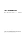
Topsy on the Palm Pilot
Diploma Thesis by Gabriele Giambonini – DA-2001.12
November 2000 – February 2001
Computer Engineering and Networks Laboratory (TIK), Zürich
Supervisors: Lukas Ruf, Matthias Bosshardt
Professor: Bernhard Plattner
2
Abstract
Since some years, the new trendy in computer market seems to grow towards
the offer of more functionality such as WAP, date-book, bank-transactions and
address book for portable systems like cellular phones or palm-tops. Normally,
such systems are based on a monolithic operating system, specially designed for
an unique architecture; thus until now the efforts to led to the creation of OS for
multiple architecture brought to unsatisfiable results.
The Computer Engineering and Networks Laboratory (TIK) of the Swiss Federal
Institute of Technologies has developed a new OS: Topsy. Originally designed
for teaching purpose of practical exercises related to the courses, its simplicity,
readability, transparency and hardware independence, led quickly to implementations for different platforms. Moreover, Topsy is available under the Gnu Public
Licence (GPL). Due to all its properties, Topsy is then a very good candidate to
be introduced in this new emerging technologies.
Leader on the market of PDAs is actually the Palm Inc. with its Palm Pilot; moreover emulators for this platform are free available on Internet. These preconditions lead to the idea of an implementation of Topsy for the Palm Pilot. The GNU
utilities (C-compiler, assembler, linker) and the GNU/Linux platform can be used
for the port in order to keep all the work available under the GPL.
This diploma work presents the porting of Topsy’s hardware abstraction layer
(HAL) for the Palm Pilot, using the xcopilot emulator. This functioning basis
offers the possibility of further development of this OS on the Palm platform in a
very quick and easy way.
Contents
1 Introduction
8
2 Material and Methods
2.1
2.2
2.3
10
Palm . . . . . . . . . . . . . . . . . . . . . . . . . . . . . . . . . . . . . . . . . . .
10
2.1.1
MC68328 architecture . . . . . . . . . . . . . . . . . . . . . . . . . . . . .
11
2.1.2
The xcopilot emulator . . . . . . . . . . . . . . . . . . . . . . . . . . . . .
15
The GNU C suite . . . . . . . . . . . . . . . . . . . . . . . . . . . . . . . . . . . .
15
2.2.1
The software . . . . . . . . . . . . . . . . . . . . . . . . . . . . . . . . . .
16
2.2.2
Compilation and installation . . . . . . . . . . . . . . . . . . . . . . . . . .
16
2.2.3
GCC . . . . . . . . . . . . . . . . . . . . . . . . . . . . . . . . . . . . . .
18
Topsy . . . . . . . . . . . . . . . . . . . . . . . . . . . . . . . . . . . . . . . . . .
19
3 Results
20
3.1
Startup . . . . . . . . . . . . . . . . . . . . . . . . . . . . . . . . . . . . . . . . . .
20
3.1.1
Loading the kernel . . . . . . . . . . . . . . . . . . . . . . . . . . . . . . .
20
3.1.2
The logo . . . . . . . . . . . . . . . . . . . . . . . . . . . . . . . . . . . .
22
Memory . . . . . . . . . . . . . . . . . . . . . . . . . . . . . . . . . . . . . . . . .
23
3.2.1
The kernel file . . . . . . . . . . . . . . . . . . . . . . . . . . . . . . . .
23
3.2.2
Memory layout . . . . . . . . . . . . . . . . . . . . . . . . . . . . . . . . .
24
Threads . . . . . . . . . . . . . . . . . . . . . . . . . . . . . . . . . . . . . . . . .
27
3.3.1
Interrupts handling . . . . . . . . . . . . . . . . . . . . . . . . . . . . . . .
27
3.3.2
Threads management . . . . . . . . . . . . . . . . . . . . . . . . . . . . . .
30
Topsy . . . . . . . . . . . . . . . . . . . . . . . . . . . . . . . . . . . . . . . . . .
31
3.4.1
System-calls . . . . . . . . . . . . . . . . . . . . . . . . . . . . . . . . . .
31
3.4.2
A small math-library: AsmRoutines.S . . . . . . . . . . . . . . . . . . . .
32
3.4.3
Assembler support: SupportAsm.c . . . . . . . . . . . . . . . . . . . . . .
33
3.4.4
MC68328 registers description: cpu.h . . . . . . . . . . . . . . . . . . . . .
33
Input/Output (IO) . . . . . . . . . . . . . . . . . . . . . . . . . . . . . . . . . . . .
33
3.2
3.3
3.4
3.5
CONTENTS
5
3.5.1
IOConsole . . . . . . . . . . . . . . . . . . . . . . . . . . . . . . . . . . .
33
3.5.2
The driver . . . . . . . . . . . . . . . . . . . . . . . . . . . . . . . . . . . .
34
4 Discussion and outlook
35
4.1
Discussion . . . . . . . . . . . . . . . . . . . . . . . . . . . . . . . . . . . . . . . .
35
4.2
Outlook . . . . . . . . . . . . . . . . . . . . . . . . . . . . . . . . . . . . . . . . .
36
4.2.1
Debugging . . . . . . . . . . . . . . . . . . . . . . . . . . . . . . . . . . .
37
4.2.2
Topsy enhancements . . . . . . . . . . . . . . . . . . . . . . . . . . . . . .
38
4.2.3
Palm-related enhancements . . . . . . . . . . . . . . . . . . . . . . . . . .
39
5 Acknowledgements
41
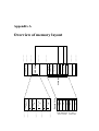
A Overview of memory layout
45
Bibliography
45
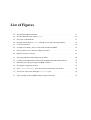
List of Figures
2.1
The MC68328 Block Diagram. . . . . . . . . . . . . . . . . . . . . . . . . . . . . .
11
2.2
The MC68EC000 status register “%sr”. . . . . . . . . . . . . . . . . . . . . . . . .
12
2.3
The stack on MC68EC00 . . . . . . . . . . . . . . . . . . . . . . . . . . . . . . . .
12
2.4
Interrupt Vector Register “IVR”, interrupt vector table, interrupt handlers . . . . . .
14
2.5
LCD screen format. . . . . . . . . . . . . . . . . . . . . . . . . . . . . . . . . . . .
14
2.6
Example of available “skins” for the Palm emulator xcopilot. . . . . . . . . . . . . .
16
2.7
Stack layout by GCC function-calling convention . . . . . . . . . . . . . . . . . . .
18
2.8
Modular structure of Topsy. . . . . . . . . . . . . . . . . . . . . . . . . . . . . . . .
19
3.1
How the painted and the displayed logo differs. . . . . . . . . . . . . . . . . . . . .
22
3.2
Creation of the kernel file starting from the kernel.out and user.out object. . . . . .
23
3.3
RAM layout for Topsy using the xcopilot emulator. . . . . . . . . . . . . . . . . . .
26
3.4
Exceptions assignment in Topsy . . . . . . . . . . . . . . . . . . . . . . . . . . . .
27
3.5
How syscallhandler saves the context of kernel and user threads. . . . . . . . .
29
3.6
The layout of the stack during the trap-rte cycle. . . . . . . . . . . . . . . . . . .
30
4.1
Topsy running on the xcopilot and the output of the shell. . . . . . . . . . . . . . . .
36
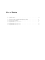
List of Tables
2.1
PalmPilot history. . . . . . . . . . . . . . . . . . . . . . . . . . . . . . . . . . . . .
10
3.1
Example of output during the setup of the memory layout. . . . . . . . . . . . . . .
21
3.2
Error exception assignment. . . . . . . . . . . . . . . . . . . . . . . . . . . . . . .
28
3.3
Implementation of restoreSuper . . . . . . . . . . . . . . . . . . . . . . . . . .
31
3.4
Implementation of MsgSendAsm. . . . . . . . . . . . . . . . . . . . . . . . . . . .
32
3.5
Implementation of MsgRecvAsm. . . . . . . . . . . . . . . . . . . . . . . . . . . .
32
Chapter 1
Introduction
During the last years, the classical idea of the PC as a multi-purpose device is declining. Thanks to
the new technologies in miniaturisation, the power of a mid/low-range PC is available for portable
systems like cellular phones or palm-tops. Thus, more functionality can be embedded into these
devices, an example can be the tools available in cellular phones or the growth of the palm-tops
market.
Technologies are expected to merge: The phone, the fax, the calculator, the camera, the tape recorder,
the walk-man, etc. might develop into one little machine, a true personal digital assistant (PDA).
Nowadays, several companies are fighting to get the best position in this market. For example Microsoft with its WinCE [1] is trying to offer the look and feel of Windows on a large variety of
devices, and Palm Inc. [2] a very simple and compact OS. Unfortunately WinCE suffers many problems related to the heterogeneity of the hardware and software incompatibilities, while PalmOS [3]
is available only for MC68328-based [4] handhelds. Until now, no one seems to be able to offer a
stable, portable, simple and well-designed operating system for PDAs.
These characteristics can be found in Topsy [5], an operating system developed by the Computer
Engineering and Networks Laboratory (TIK) of the Swiss Federal Institute of Technologies. It is
released under the Gnu Public License (GPL) and offers many interesting features: Topsy is very thin
(compiled is about 100Kbytes), is portable, the code is highly readable because of its teaching-purpose
nature (Topsy stands for Teachable OPerating SYstem) and it is not over-featured.
The aim of this work is to present the port of this OS for the Palm Pilot platform, chosen because
of its success in the PDA market and because of its very simple and clean hardware design: Today
Palm Inc. is the leader in market (PalmOS powers over 75% of the worldwide personal companion
market [6]) with its very popular series of handhelds based on MC68328 and MC68EZ328 DragonBall processors [7]. The offered operating system, is used on other similar devices produced by
Handspring [8], Sony [9], IBM [10], Kyocera [11], etc. [12].
Topsy has been already implemented for an IP-Phone [13] that uses a processor similar to the one
present in the Palm platform, belonging to the Motorola 68000 family [14]. However, the architecture of the PDA used for this work is far more complex because of differences in the processor
itself, the presence of a liquid crystal device, serials ports, etc. Moreover, the compiler utilised (GNU
C-compiler: GCC [15]) is rather different in handling the assembler code: Most of the machinedependant code has to be rewritten from scratch.
Starting with the first model of Palm, the Pilot1000 produced in 1996 by U.S. Robotics (Tab. 2.1), the
Open Source community was amazed by this new product of the technology. The Palm became quick
a “must-have” and was not surprising that after a short time an emulator, named xcopilot and based
on the code of the Unix Amiga Emulator (UAE [16]), was implemented.
CHAPTER 1. INTRODUCTION
9
Nowadays, xcopilot is not more supported by Palm Inc. because of a new environment for developing
PalmOS-specific applications: The Palm OS Emulator (Pose) [17]. Fortunately, thanks to the porting
of Linux ( Linux project) to the Palm [18], the product is still supported by the Open Source
community, and new features specially designed for the development of embedded operating systems
will be added in the near future.
The comfort of using an emulator running on the same environment of the creation of the Topsy code,
lead to the decision to not use the Motorola development-board [19].
This work will present the port of Topsy to the Palm models based on the MC68328 DragonBall
processor. The xcopilot emulator was used as device. All the tools utilized for this purpose and the
results produced, are released under the GPL. A version for MC68EZ328 processor (PalmVx) is also
available, but not tested.
Chapter 2
Material and Methods
In this chapter, the tools used to port the Topsy’s Hardware Abstraction Layer (HAL) to the Palm are
presented.
The host machine used for the work is an Intel-Pentium based PC and the operating system is
GNU/Linux (SuSE distribution version 7.0 [20]). The compiler utilised is the GNU C-compiler
(GCC) and the Palm emulator is xcopilot.
2.1
Palm
Date
Models
Mar 1996
Pilot1000, Pilot5000
Mar 1997
PalmPilot Professional, PalmPilot Personal Edition
Mar 1998
Palm III
Feb 1999
Palm IIIx, PalmV
May 1999
PalmVII
Jul 1999
PalmIIIe
Feb 2000
PalmIIIc
Aug 2000
PalmVIIx, Palm m100
Table 2.1: Brief history of models of the PalmPilot. In May 1997, 3Com purchased
U.S.Robotics and got Palm Computing Inc. as a bonus
The latest two models of Palm Pilot produced by the 3COM are based on two very similar processors:
The Motorola MC68328 [4] and the Motorola MC68EZ328 [7]. The latter is also present in the
PalmV, while the PalmIII models use the other processor.
The emulator used during this work, xcopilot 0.6.6, is based on the MC68328 processor, while the
newest Pose [17] uses the MC68EZ328. Unfortunately Pose is not a real emulator of the whole
hardware, it can be considered as system for developing and testing applications specifically designed
for PalmOS. This is the reason why the no anymore supported xcopilot has been chosen by the
Linux1 team and for this work.
1
Pronounced “you-see-linux”
CHAPTER 2. MATERIAL AND METHODS
2.1.1
11
MC68328 architecture
The purpose of this section is to give an overview of the architecture of the MC68328 in order to
provide the basics for the next chapters.
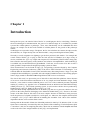
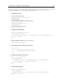
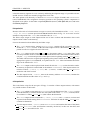
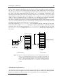
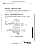
The MC68328 DragonBall combines an MC68EC000 [21] processor with peripheral modules like
liquid crystal display (LCD) controller, UART and infra-red communication support and serial peripheral interface.
Parallel I/O ports
System integration
module
8/16 bit
68000 BUS
interface
Enhanced
real-time
clock
in-circuit
emulation
controller
68EC000 HCMOS
static
core
16bit
timer
module
Interrupt
680EC000 internal bus
DRAM
controller
bootstrap
mode
phase-locked
loop and
power control
LCD
SPI
PWM
controller
uart
with
infrared
support
Parallel I/O ports
Figure 2.1: The MC68328 Block Diagram.
The MC68EC000 core
The MC68EC000 core in the MC68328 is an updated implementation of the MC68000 [14] 32-bit
microprocessor architecture.
The main features of the core are:
Low power, static HCMOS implementation.
32bit address bus and 16bit data bus.
Sixteen 32bit data and address registers.
56 instruction types.
14 addressing modes and five main data types.
Seven priority levels for interrupt control.
Big Endian data format.
Supervisor- (privileged) and user-mode.
12
CHAPTER 2. MATERIAL AND METHODS
The M68EC000 programming model consists of two register groups: User and supervisor. User programs executing in the user mode only use the registers in the user group. System software executing
in the supervisor mode can access all registers and use the control registers in the supervisor group to
perform supervisor functions.
The 16 general-purpose registers are divided into two categories: The first eight registers (%d7-%d0)
are data registers that are used for byte (8bit), word (16bit) and long-word (32bit) operations. The next
seven registers (%a6-%a0) and the stack pointer (%a7/%sp) can function as base address registers or
index registers for long and long-word operations. Register %a7 is used as a hardware stack pointer
during stacking for subroutines calls and exception handling.
In supervisor mode, the upper byte of the status register (%sr) can also be programmed.
Fig. 2.2 shows the value of the bits composing the status register.
supervisor mode
15 14 13 12 11 10
%sr
T
0
S
0
0
l2
user mode
9
8
7
6
5
4
3
2
1
0
l1
l0
0
0
0
X
N
Z
V
C
Figure 2.2: The status register (%sr) contains the interrupt mask with seven available
levels (l2, l1, l0), as well as extend (X), negative (N), zero (Z), overflow
(V) and carry (C) condition code. The T bit indicates when the processor
is in trace mode and the S bit indicates when it is in supervisor (S=1) or
user mode (S=0).
The stack on MC68EC000
The stack on the MC68EC000 grows from the high memory to the low memory. By using the convention to visualise the stack with the address 0x00000000 on the top and the address 0xffffffff
on the bottom, the analogy of “pushing” data on the stack and to “pop” them is simple to keep in
mind.
0x00000000
free
"push"
Value3
"pop"
"push"
Value2
"pop"
"push"
Value1
"pop"
0xffffffff
4 bytes
Figure 2.3: The stack pointer is automatically increased each time a value is pushed
on the stack and decreased for each “pop” operation.
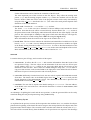
Fig. 2.3 gives an example of the stack after three push-operations. To restore the original situation,
three pop-operations are required.
To implement stack growth, -(%sp) (pre decrement) is used to push data and (%sp)+ (post incre-
CHAPTER 2. MATERIAL AND METHODS
13
ment) to pop from the stack. After each operation, the stack pointer register points to the top item
on the stack. The example of Fig. 2.3, is the result of three push-operations and three pop-operations
(Tab. 2.1.1).
move.l Value1, -(%sp)
/*
Push Value1 on the stack
*/
move.l Value2, -(%sp)
/*
Push Value2 on the stack
*/
move.l Value3, -(%sp)
/*
Push Value3 on the stack
*/
/*
Value3 available at (%sp)
*/
/*
Value2 available at -4(%sp)
*/
/*
Value1 available at -8(%sp)
*/
move.l (%sp)+, %d3
/*
Pop Value3 from the stack
*/
move.l (%sp)+, %d2
/*
Pop Value2 from the stack
*/
move.l (%sp)+, %d1
/*
Pop Value1 from the stack
*/
/*
Value3 available in %d3
*/
/*
Value2 available in %d2
*/
/*
Value1 available in %d1
*/
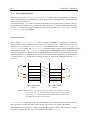
The interrupt handling
The MC68328 offers 256 interrupts. This means the vector number is an 8bit digit (Interrupt Vector
Register, IVR). The vector number will be multiplied by 4 to obtain the address of the exception
vector. The exception vector is the memory location from which the processor fetches the address of
the routine that will handle the exception. For simplicity, the value of IVR can be seen as an index
into an array of addresses of functions. The table of exception vector occupies 1Kbyte of memory
(each address is 4Byte long: 256*4=1024) and it is starting at 0x00000000 (Fig. 2.4).
Interrupts are processed in the following sequence:
1. The interrupt controller collects interrupt events, prioritises them and presents the highest to the
core processor (if there are no higher interrupts pending).
2. The core processor responds to the interrupt request by executing an interrupt acknowledge bus
cycle after the completion of the current instruction.
3. The interrupt controller recognises the interrupt acknowledge cycle and places the interrupt
vector for that interrupt request onto the core processor bus.
4. The core processor reads the vector and address of the interrupt handler in the exception vector
table and executes code at that address.
More informations about the use of the interrupts in Topsy can be found in 3.3.1.
LCD controller
The LCD controller is used to display data on an LCD module. It fetches display data from system
memory through periodic DMA transfer cycles. It supports monochrome LCD module with a maximum of sixteen gray levels.
14
CHAPTER 2. MATERIAL AND METHODS
RAM
IVR
0x0000 0000
0
*handler0()
1
*handler1()
2
*handler2()
0x0000 0004
0x0000 0008
0x0000 000c
...
...
...
*4
Exception
vector
table
0x0000 03fc
7
*handler255()
0x0000 0400
4 Bytes
Figure 2.4: The value of Interrupt Vector Register (“IVR”) is multiplied by 4 to obtain
the address of an exception vector. The exception vector is the memory
location from which the processor fetches the address of the routine that
will handle the exception (*handler0(), . . . , *handler255()).
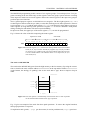
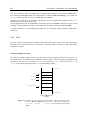
The screen width and height of the LCD panel are software programmable using the LXMAX (width)
and LYMAX (height) registers. The LCD controller starts scanning the display memory at the location
pointed by the LCD screen starting address register (LSSA). The maximum page width and height
are specified by the LCD virtual page width (LVPW) and height (LPVH) registers: By changing the
value of the LSSA register, a screen-sized window can be vertically or horizontally scrolled anywhere
inside the virtual page boundaries (Fig. 2.5).
Screen starting
address (LSSA)
Screen width (LXMAX)
Screen height (LYMAX)
Virtual page height (LPVH)
Virtual page width (LPVW)
Figure 2.5: LCD screen format.
CHAPTER 2. MATERIAL AND METHODS
2.1.2
15
The xcopilot emulator
xcopilot is an emulator of 3Com Palm that runs on Unix systems under X11 [22]. For some years,
it has not been supported anymore because of Pose. Unfortunately, the official home page 2 doesn’t
seem to be available, but the latest version of the emulator (0.6.6, 6 September 1998) can still be
downloaded from the home page of the Linux project [23]. A patched version which fixes a few
bugs when doing shared memory on the Linux-Slackware distribution is also available [24].
xcopilot doesn’t seem to work properly with the newest linux-kernel: The emulator doesn’t even start
with the version 2.4.1; with linux-kernel version 2.2.17 it functions properly.
Debugging
xcopilot offers two methods for debugging applications. One method uses gdb but is available only
under PalmOS because of the need of the “gdb panel” application. The other is turned on by using
the -debug command-line option: It starts a third process that acts as a debug server attached to the
TCP-port number 2000. Unfortunately, even this possibility seems to be unavailable in the current
version of xcopilot: Investigations with the netstat utility don’t reveal the presence of this listening
port.
The method used in this work to debug the Topsy kernel is based on the memory dump generated by
xcopilot when quitting: The file pilot.ram present in the Topsy main directory is the image of the
4Mb of RAM between 0x1000000 and 0x10400000. The utility used to analyse the binary file
is hexdump: Because of the endianess differences between Intel and Motorola architecture, the hex
utility used for the logo leads to incorrect values.
Because of the success of Linux, some patches have been applied to xcopilot. The most interesting (but still not 100% working) gives the possibility to put breakpoints in the code and use gdb
(m68k-coff-gdb) as debugging tool. At this time, only a pre-alpha patched version of xcopilot
is available [25]. For more information about the build of xcopilot and how to add the debugging
features in Topsy, follow the instruction of the file README.gdbstub included in the emulator’s
package. For an overview about debugging methods, refer to Sec. 4.2.1.
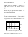
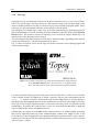
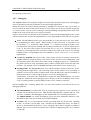
“Skins”
There is the possibility to personalise the look of xcopilot by changing its “skin”. Skins are graphical
files in XPixmap (.xpm) format that can replace the original one (Fig. 2.6). The new graphical
interface of the emulator can be substituted using any draw program, for example, The Gimp. To
change the look of xcopilot, simply copy the new skin with name case.xpm in the emulator’s main
directory, remove the display.o file and compile. Nevertheless, the apparency of the emulator is
not important for its correct functioning.
2.2
The GNU C suite
The spirit of this work is to release the port of Topsy under the GPL. For coherence with this idea, the
materials used have to be available with the same licence.
The Gnu C-compiler (GCC) is one of the most famous products of the Free Software Foundation and
2
http://xcopilot.cuspy.com
16
CHAPTER 2. MATERIAL AND METHODS
(a) Hippie
(b) Horizon
(c) Marple
(d) Stylish
Figure 2.6: Four “skins” available for xcopilot. Other examples are available at
http://www.the-labs.com/PDA/
produces code for various architectures, including the MC680003 .
This section explains how to build a cross-compiler, in this case that means a C-compiler, assembler,
linker, debugger, libraries and utilities that run on an Intel platform (“host”) but are used to generate
code for the m68k (“target”). More informations can be found on the HOWTO [26].
2.2.1 The software
First of all, a compiler has to be already available on the host machine in order to build the needed
tools, and, moreover it must include support for m68k code. GCC contains m68k support starting
from version 2.7.1; in this work the version used is 2.95.2.
In this work, the following tools (available in every mirror of the GNU site [27]) were used:
Assembler, linker, utilities: binutils-2.10.
Compiler: gcc-2.95.2.
Debugger: gdb-5.0.
Library: glibc-2.2 or newlib-1.8.2.
GLIBC is generally better for larger (unix-based) systems, while newlib is more appropriate for embedded applications. Thus, the latter was chosen. An alternative to GLIBC can be the diet libc [28],
but unfortunately this library is only static. Another library, expecially designed for embedded systems, is uClibc [29]. Unfortunately, at this moment it is available only for Intel architecture, a port
for m68k architecture is expected.
2.2.2 Compilation and installation
Creating and installing a cross compiler on a Linux-box is quite simple. First of all, the downloaded
archives [30] have to be unpacked into a temporary directory, for example in /tmp. Then the system
3
For coherency with the GNU documentation, from now the term “m68k” will be used to identify the Motorola
MC68000 processor
CHAPTER 2. MATERIAL AND METHODS
17
has to be configured, the tools have to be compiled and installed. Just change directory to /tmp and
follow the steps below: The cross-compiler is installed into /usr/local/cross-gcc:
1. Configure the system:
Set the destination directory:
prefix=/usr/local/cross-gcc
Set target system:
target=m68k-coff
Set the directories created by unpacking sources:
gccdir=gcc-2.95.2
newlibdir=newlib-1.8.2
gdbdir=gdb-5.0
Create the destination directory:
mkdir -p $prefix
2. Compile and install binutils:
mkdir -p build$binutilsdir
cd build$binutilsdir
../binutilsdir/configure --target=$target --prefix=$prefix -v
make all install
cd ..
3. Add executables to path (they’ll be needed later):
PATH=$PATH:$prefix/bin
4. Add symbolic links to newlib into GCC source:
cd
ln
ln
cd
$gccdir
-s ../$newlibdir/newlib newlib
-s ../$newlibdir/libgloss libgloss
..
5. Compile and install gcc and newlib:
mkdir -p build$gccdir
cd build$gccdir
../$gccdir/configure --target=$target --prefix=$prefix \
--with-newlib --enable-languages -v
make all install
cd ..
6. Compile and install gdb:
mkdir -p build$gdbdir
cd build$gdbdir
../$gdbdir/configure --target=$target --prefix=$prefix -v
make all install
cd ..
18
CHAPTER 2. MATERIAL AND METHODS
The cross-compiler will not substitute the existing utilities because of the prefix “m68k-coff-”.
For example the objcopy utility for m68k objects is named m68k-coff-objcopy. To include the
$prefix directory, the $PATH env-variable has to be updated.
In order to save disk space, it would be a good idea to recursively delete the contents of the build
subdirectories at the end of the process.
This configuration works for embedded systems only because of newlib. Problems can arise while
building a cross-compiler for Solaris: The header files for Solaris aren’t provided by newlib.
A good resource for cross-compiling informations is the frequently asked questions (FAQ) document [31].
2.2.3 GCC
In order to better understand the assembler routines described later in this work, some knowledge
about how GCC passes parameters to functions (“function-calling convention”) and about inlineassembly is needed.
Function-calling convention
The GNU C Compiler pushes on the stack the values to pass to functions and uses the register %d0
for return-values. The parameters are pushed from left to right: That means that, using 4bytes-long
parameters, the first one is located at 4(%sp), the second at 8(%sp), and so on (Fig. 2.7). At
(%sp) is present the program counter (%pc) of the calling routine.
0x00000000
%sp
...
8(%sp)
(4*n)(%sp)
%pc
param1
param2
...
4(%sp)
paramn
0xffffffff
4 bytes
Figure 2.7: Example of stack layout by GCC function-calling convention, after
the BSR (Branch SubRoutine) instruction. The function example is
f(param1, param2,. . . , paramn) and all parameters have length
4Bytes.
CHAPTER 2. MATERIAL AND METHODS
19
Inline assembly
With the GNU C Compiler it is possible to mix assembler in C code. This can result to be very
comfortable especially for very short routines. GCC uses the assembler “as” (m68k-coff-as) as a
backend, the syntax used is known with the name “AT&T” syntax. For more informations, refer
to [32].
2.3
Topsy
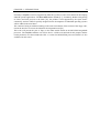
Topsy is a small operating system which has been designed by the Computer Engineering and Network Laboratory (TIK) of the Swiss Federal Institute of Technologies in Zürich (ETHZ). This OS
was designed for teaching purposes (Topsy stands for Teachable OPerating SYstem) in practical exercises related to the courses, and its simplicity, readability, transparency and hardware independence,
led quickly to implementations for different platforms.
Characteristic:
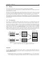
Topsy is a multi-threaded operating system; that means all threads of a specific process (kernel or
user) are running in one address space and may share global memory. Thus, the memory is divided
into two address spaces: One for user threads and the other one for the threads that belong to the
kernel.
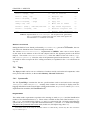
Topsy is modular, that means the kernel contains three main modules reflecting the basic tasks performed by the OS: The memory manager, the thread manager and the I/O subsystem. The communication system is the same as in user threads, based on sending and receiving messages (messagepassing), this provides a quick response to interrupts and synchronisation between modules.
For an overview on the structure of the Topsy Operating System, please refer to [5].
User
Kernel
Topsy
Threads
I/O
Memory
Error
HashList
TMIPC
TMInnit
IOConsole
IODevice
MMHeapMemory
MMInit
List
Lock
Support
Syscall
TMMain
TMScheduler
IOMain
MMMain
MMVirtual
TMThread
TMTime
Drivers
Serial
AsmRoutines
TMClock
TMError
TMHal
IOHal
Exception
PrintReg
SendReceive
Portable
code
Startup
−Memory
Startup
MMDirect
logo
−Mapping
MMError
main
romvec
TMHalAsm
SupportAsm
start
Hardware−
dependent
code
SyscallMsg
Hardware Abstraction Layer (HAL)
Figure 2.8: Modular structure of Topsy. The boxes named Threads, I/O and Memory are the main Topsy modules, while the dotted Topsy-box can be
seen as a collection of routines used by the other kernel components. The
Startup-box contains the routines involved only during system startup.
Fig. 2.8 gives an overview about the portable part of Topsy and the files related to this work.
Chapter 3
Results
3.1
Startup
This section will present the boot sequence of the Topsy kernel on the xcopilot emulator, starting
from the load of the kernel and ending to the call of the portable topsyMain() function.
The chapter will also comprise the creation of the logo displayed on the LCD.
3.1.1 Loading the kernel
The xcopilot emulator, discussed in 2.1.2, needs “basic” parameters to start (for example the name of
the kernel to load) while other parameters are optional.
In order to simplify the setup of the emulators for the correct load and run of Topsy, a little shell-script
has been created and placed in the main Topsy directory with the name xc.sh. The script is invoked
by passing, as first and unique parameter the name of the kernel image, in this case kernel.
The first thing xc.sh does, is to delete old memory dumps generated previously by the emulator
(files pilot.ram and pilot.scratch), it loads then the specified kernel and cleans the console once the
xcopilot ends. This last step is needed because of the “dirty” output generated on the console by the
emulator itself.
The optional parameters embedded into the script take care to double the dimension of the graphical interface of the emulator (-double) and to avoid the use of the X-Window shared memory
(-noxshm). After some hundreds consecutive runs of the emulator, a memory leak has been noticed
(”shmget: No space left on device”) and the graphical system had to be shut down and restarted. It is
still not clear if the problem is related to xcopilot or to the version 3.3.6 of X-Window .
The parameter -ramsize 4096 is used to set the dimension of the RAM to 4MB (the value is
expressed in Kbytes), but it is not absolutely necessary because it reflects the default value used by
xcopilot.
A very important parameter is the location of the datadir, it must be set to “current directory”
(-datadir .) in order to correctly locate the kernel-file, even if specified with the parameter
-romfile.
The first stage: Processor setting and data copying
The first step the emulator will perform after the correct load of the kernel, is to set the value of
the program counter register at the memory address of start, that means on the beginning of the
CHAPTER 3. RESULTS
21
assembler routine start.S.
In order to quickly recognise the start point of the kernel during the debugging phase, the word
“boot” compares at the beginning of the code. With the purpose of avoiding the interpretation of
this label as an instruction, a jump instruction is needed to automatically skip this not-instruction.
This trick could seem a bit complicate at the beginning, but it resulted to be a great help during the
assemblage of the kernel, thus it has not been removed.
The code of start.S is well documented, it makes no sense to discuss it deeply here, so only a short
description of the main functions will follow. Five are the main things this assembler-code does before
the memory configuration (second stage):
1. It sets some processor-specific registers, for example it turns off the watchdog. Some registers are memory-mapped differently in the newest MC68EZ328 processor: A rough support is
included here, but still not tested.
2. It sets the serial in order to give the possibility to send immediately informations in case of
errors. The transmission parameters are 9600 baud, 8 bits of data, no parity and 1 stop-bit
(9600/8N1).
3. It sets the LCD dimension and address of the logo (Sec. 2.1.1). The logo is displayed on the
Palm LCD.
4. It copies the chunk of kernel variables from the address given by the label placed at the end
of the .logo section to the memory address 0x10000400. For more informations about the
memory layout, please refer to Sec. 3.2.2.
5. It copies the user data and user code to the RAM, starting at 0x10100000 and 0x10200000.
The procedure used to locate the beginning and the dimension of the user portion in the ROM
is explained in Sec. 3.2.1.
The second stage: Memory configuration
The C-function setup() invoked as last operation by start.S, is responsible of the setup of the
memory layout.
The description of the system memory is available by the header-file MemoryLayout.h. The main
task of the setup() function is to set the values of the structure segmap, values needed to correctly configure the memory regions. Before passing the control to the topsyMain() routine, the
second stage prompts on the console the memory division, as shown in Tab 3.1.
kernelCodeSize
0x00010000
kernelCodeStart
0x10c10000
kernelDataSize
0x000e1000
kernelDataStart
0x10002c00
userCodeSize
0x00100000
userCodeStart
0x10100a6e
userDataSize
0x00200000
userDataStart
0x10200000
Table 3.1: Example of output during the setup of the memory layout. The values
reflect the description on Appendix A
More informations about the layout of the memory can be found at 3.2.2.
22
CHAPTER 3. RESULTS
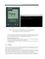
3.1.2 The logo
Originally the logo was displayed on the screen to show up the boot process, it was a sort of alarmbell in case of boot failure. The logo consists in a 160x160 pixel image with 1bit colour depth, in the
future it could be possible to use four or sixteen-level gray scale according to the palm model. Please
refer to [4] for more informations about the LCD controller of the MC68328.
The generation of a suitable logo is quite easy: It could be painted using any painting program (in
this work The Gimp 1.1.24 was used) that gives the possibility to export the picture in the Windows
Bitmap format. This format is used for its simplicity, even if it stores the images “bottom up”: It is
thus necessary to flip the image before saving it.
The colour depth of the image must be set to one bit (or “black and white”, depending on the notation
used by the painting tool) , with the background colour “black”.
Fig. 3.1 shows an example of how the the logo used in this work looks in the painting program and
on the emulator display.
Figure 3.1: Example of the painted logo (left) and the displayed one (right). Because
of the Windows Bitmap format, the picture has to be flipped upsidedown. Note that the white colour will be interpreted as black by the Palm.
It is still not possible to directly put the saved picture onto the kernel code, it is necessary to transform
it into a suitable format. The logo.c file is simply a sequence of bytes values encapsulated into the
asm("...") notation. In order to transform the logo from the .bmp format to .c representation, a
little shell script named logo.sh has been written and placed in the directory where logo.c will reside.
The script accepts as input argument the name of the picture previously saved, and generates the file
named logo.c. To perform the creation of the C-source, the script needs the hex utility to dump the
logo in CP/M-like hex format, and awk to process it.
Unfortunately, the picture saved in BMP-format could result not to be 160bits-aligned, generating
thus a left or right-shift of the logo on the emulator display (160bits is the length of a line on the
LCD). Moreover, the not-alignment leads to problems during the generation of the C-source and consequently the last 16Bytes of the file (reflecting the first 128 bits of the picture) have to be overwritten
with zero-values (“white”).
CHAPTER 3. RESULTS
3.2
23
Memory
This section will discuss the layout of the memory by running Topsy on xcopilot.
The emulator offers a write-protected memory-area (ROM) with a dimension of 512Kbyte that reflects
the flash-ROM of a real Palm.
The kernel code and the displayed logo reside in that location, while the kernel data, user code and
user data are copied from ROM to the RAM during the early boot stage (See 3.1.1). Even if the latest
models of Palm offer up to 8MB of RAM, for Topsy, a model with 4MB resulted to be sufficent.
The layout may vary using other emulators (for example Pose) or on a real Palm, further informations
are needed in order to port Topsy on such devices. The required modifications are minimal and located
only in few files.
3.2.1
The kernel file
The purpose of the auto.sh script placed the Topsy main directory is to automatise the task of the
kernel creation: It cleans old files, it compiles the new kernel object-file and it dumps a suitable one.
kernel.out
code
logo
objdump, cat
data
romvec
kernel.topsy
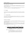
The kernel file needed by xcopilot is generated starting from the kernel.out and user.out files that
result from the compilation (Fig. 3.2). In order to produce the file needed by the emulator, the objcopy
utility will be used. The GNU utility m68k-coff-objcopy is invoked with the purpose of essentially
produce a memory dump of the contents of the input object file. Please refer to [33] for more informations about the copy process from an object file to another. The last operation performed by the
script is to use the cat command to produce an unique kernel file loadable by the emulator.
Kernel file
romvec
romvec
code
code
logo
logo
data
user.out
code
objdump, cat
data
romvec
user.topsy
cat
data
romvec
romvec
code
code
data
data
Figure 3.2: Schematic representation of the kernel creation. The script auto.sh
generates a suitable kernel file by using objcopy and the cat utilities.
kernel.out
It is the result of the compilation of the Topsy’s kernel. It consists of three parts that will be extracted by m68k-coff-objcopy, saved as files and and re-arranged using cat in order to produce the
kernel.topsy file (Fig. 3.2):
1. kernel.romvec: Reflects the file romvec.c in the Startup/palm directory. It has a fixed dimension of 65Kbytes and contains informations about the “card”, for example name and version.
24
CHAPTER 3. RESULTS
Further informations can be found in the comments of the file itself.
The most important part of this section are the first 8bytes: They reflect the starting stack
pointer (%sp) and the starting program counter (%pc) values the emulator will set once the
kernel is loaded. While the correct value of the program counter can be easily determined by
using the value of start described in Sec. 3.1.1, the value of the stack pointer depends of the
dimension of the RAM and has to
2. kernel.code: Contains the .code and the .logo sections.
The kernel .code in this case has a dimension of about 25Kbytes and contains the kernel
functions. Note that the code will be executed directly from the ROM. The .logo section is
the picture shown on the LCD display and its dimension reflects the one of the display: 160x160
pixels at 1bit colour depth are 3200bytes, that means a little more than 3Kbytes. The logo file,
logo.c can easily be created starting from a BMP file using the logo.sh utility.
More informations about the creation of the logo can be found in Sec. 3.1.2
3. kernel.data: The last section contains the initialised and uninitialised variables used by the
kernel (.data, .bss and COMMON). During the kernel boot-process these variables are copied
in the RAM, starting from the location 0x10000400. In order to find the boundaries of the
data, the labels logo end and rom dataend are used as start and endpoint of the section.
More informations about the kernel variables can be found in Sec. 3.1.1.
user.out
It contains the user part of Topsy, and it consists of three parts:
1. user.romvec: It reflects the file head.c and contains informations about the layout of the
user portion of Topsy. The first 4 bytes are the dimension of the user code, the next 4 bytes
are the address of the main() routine in user space (the shell) and the last 4 bytes are the
dimension of the user-data. These values are needed during the setup (Sec. 3.1.1) in order to
copy user-data and user-code from the ROM to the right place in the RAM. The kernel knows
that these 12 bytes are located just at the end of its data portion.
2. user.code: Differently from the kernel code, the user code is copied in the RAM and executed
from there. The kernel code, in the ROM, begins where the rom dataend ends, plus the
(fixed) dimension of the user.romvec section. The dimension of the code is present in the
user.romvec section (label ucode size).
3. user.data: The user data is copied to the RAM, starting at 0x10200000. The start address,
in the ROM, is the end of the user code and the dimension is written in user.romvec (label
udata size).
An advantage of splitting the kernel and the user portions, is that the generated files can be easily
examined during the early development stage using the hex utility.
3.2.2 Memory layout
As explained in the previous section, the first operation the emulator does, is to read the first 8bytes
placed on the beginning of the kernel file and to assign to the stack pointer the first 4bytes and to the
program counter the last 4bytes. The execution of the code then starts from the current value of %pc.
The code will be executed directly from the ROM, even if speed losses are expected. The advantage
CHAPTER 3. RESULTS
25
is that this memory segment is set as read-only and during development stage it is possible to detect
invalid accesses on this area caused by bugged low-level code.
The stack pointer will obviously set between 0x10000000 (begin of RAM) and 0x10400000
(end of 4MB RAM). The assignment of memory portions to the operating system’s components is
described in two places: In the linker scripts link.palm.lnk (kernel), ulink.palm.lnk (user) and in the
file MemoryLayout.h.
link.palm.lnk
Because of the lack of a clear notation, as output-section is to be intended one of the .code, .data,
.logo or .romvec sections present in the kernel.out file shown in Fig. 3.2. As sections are to be
intended code portions like .text (the executable code) or .bss.
The linker script assigns to each output-section one or more sections and determines where each
output-section resides on the memory.
Four are the named-sections defined by the linker script:
The .code output-section, starting at 0x10c10000, contains all the executable code, that
means the *(.text) section. At the end of the output-section, a label named code end is
placed in order to recognise the end of the code.
The .logo output-section starts at code end, that means where .code ends: Thus, is not
necessary to define in advice a fixed dimension of the kernel code. This named-section contains
only the .logo section and presents a label placed at the beginning, named logo start.
The label will be used to recognise the beginning of the picture shown on the LCD display; the
appropriate register is set on start.S, as explained in Sec. 3.1.1. More informations about the
logo can be found at Sec. 3.1.2.
The .data output-section is placed in the kernel file after the .logo section, but in the emulator memory its position is on the RAM, at the address 0x10000400. This output-section contains the sections *(.data), *(.bss) and *(COMMON). A label, named rom dataend
marks the end of this section.
The last output-section, .romvec, starts at the memory address 0x10c00000, contains the
card-informations and the values of %pc and %sp.
ulink.palm.lnk
This is the linker script for the user part of Topsy. It consists of three output-sections, with names
very similar to those of the kernel:
The .code output-section starts at 0x10100000 plus the dimension of the .romvec section
(described below). It contains all the user-code (that means all the *(.text) sections) and at
its end there is a label ( ucode size) that reflects the dimension.
The .data output-section contains the *(.data), *(.bss) and *(COMMON) sections and
is placed in the RAM starting from 0x10200000. Placed at its end, the label udata size
contains its dimension.
The last output-section, .romvec, starts at 0x10100000 and contains the value of the labels
ucode size, main (first user-function started by the kernel, in this case the shell) and
udata size, described in Sec. 3.2.1.
26
CHAPTER 3. RESULTS
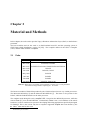
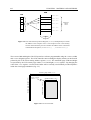
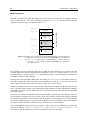
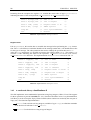
MemoryLayout.h
This file centralises the values describing the memory layout of Topsy for the xcopilot emulator
(Fig. 3.3 and Chap. A). The values are declared using the C “#define” directive and will be read
during the early boot stage, as explained in Sec. 3.1.1.
0x1000 0000
Exceptions−table
kernel−data
kernel stack
~1MB
0x1010 0000
user code
1MB
0x1020 0000
user−data
Data copied from the ROM
(mirror)
0x1000 0400
user stack
~2MB
0x1040 0000
Figure 3.3: RAM layout for Topsy using the xcopilot emulator. The filled portions
contain data copied from the ROM. The kernel-data box contains the
kernel’s .data output-section, the user-code box contains the user’s
.code plus .romvec section, and the and user-data box contains the
.data output-section.
The utilisable read/write RAM has dimension of 4MB; the first 1024 bytes are a mirror of the 256
interrupts addresses (each one of length 4bytes) located at 0x0000000. Starting from 0x10000400
kernel variables are located (section .data described previously). At the moment, the dimension of
the kernel variables is about 5Kbytes.
Starting where the kernel-data chunk ends, and ending at 0x10100000, quite 1Mbyte memory is
reserved for kernel data: That means that, at the beginning, the value of %sp has to be set to the end
of this chunk (the stack grows from the “bottom” to the “top”) minus 4bytes.
1Mbyte of memory has been reserved for the user code and the last 2Mbyte are dedicated for the user
data. A possible stack overflow of user data with possible damage of kernel informations, should be
avoided by the position of the chunk itself: By overwriting user-code, the malicious thread should
stop itself in time.
The processor of Palm, the MC68328, offers the possibility to specify up to four different classes of
devices/memory using the chip-selects register. Thus, it is possible to set the kernel portion of RAM as
read-only during execution of user-threads with the purpose to avoid illegal access to kernel portions
(the memory-mapped registers are protected from illegal access in user-mode). Further investigations
are required in this direction to determine the performance loss of such method.
Topsy will further divide the memory into regions. After some tests, the granularity of regions has
been set to 1Kbyte (“#define PAGEBITS 10” and “#define LOGICALPAGEBITS 10”):
This value is a good compromise for devices with limited resources like Palm.
CHAPTER 3. RESULTS
27
Memory Mapped registers and interrupts
As already explained in Sec. 2.1.1, the registers are memory-mapped starting from 0xfffff000. An
exhaustive description of the register can be found on Sec. 3.4.4. Refer to [4] for further informations
about the role of the registers.
The xcopilot puts a mirror of the vector table at the beginning of the RAM, that means starting from
0x10000000, as shown in Fig. 3.3. Interrupt handling is explained in Sec. 2.1.1.
3.3
Threads
The threads module in Topsy is responsable for threads initialisation and management. This chapter
will concentrate on the interrupt handling and the mechanism used for saving and restoring the thread
context.
3.3.1
Interrupts handling
The mechanism used for interrupt handling has already been explained in Sec. 2.1.1. Main purpose
of this section is to explain the handling routines related to the message passing mechanism and to
unexpected situations (“exceptions”).
Exception vector assignment
The Interrupt Vector Register (IVR) is an 8bit vector mapped at the address 0xfffff300. The
vector number provided by this register can take values from 0 to 255, that means the MC68328
supports 256 exceptions.
In this work, only two routines will be used to deal with interrupts. The syscallHandler is used
for the trap instruction, while dummyExceptionHandler is used for the remaining interrupts
(Fig. 3.4). More handling routines (designed to serve, for example, timer interrupt or I/O operations),
can be installed using tmInstallExceptionCode().
Initial SP
Initial PC
TRAP
Instruction
Vector
"Assigned"
User
Interrupt
Vector
Unassigned,
Reserved
IVR
0xfffff300
0
1
2
3
31
dummyExceptionHandler
"errorhandlers"
32
33
syscallHandler
47
48
63
64
dummyExceptionHandler
Figure 3.4: The exception generated by the “trap #n” instruction use vector number 32+n and are handled by the syscallHandler routine, while all
other interrupts, on the beginning, are assigned to dummyExceptionHandler. Vector numbers from 2 to 31 are reserved for future enhancements or assigned for specific error situations (bus error, divide-by-zero,
etc.).
255
28
CHAPTER 3. RESULTS
Exception and interrupt handling
The installation of interrupt handling is performed by initBasicExceptions() during the
startup phase. First of all, tmInstallExceptionCode() is called in order to install the 16 handlers (syscallHandler()) for the trap instructions (trap 0-trap 15). Actually, only the
first two handlers are used for message passing. The next step is the installation of exception handlers:
Because there’s no distinction between interrupts and exceptions, tmSetExceptionHandler()
installs dummyExceptionHandler() for all the 255 (MAXNBOFEXCEPTIONS) possible interrupts. The previously installed handlers are not overwritten.tmSetInterruptHandler is not executed, because of the use of a unified model without special interrupt table (MAXNBOFINTERRUPTS
is equal to 0).
tmInstallErrorHandlers() takes care to install handling routines designed for system errors,
such as attempt to access privileged resources or divide-by-zero. These routines are implemented in
TMError.c() (Tab. 3.2).
Vector number
Assignment
C-function
2
Bus Error
tmBusError()
3
Address Error
tmAddrError()
4
Illegal Instruction
tmIllInstructionError()
5
Divide-by-Zero
tmZeroDivideError()
6
CHK Instruction
tmRegisterBound()
7
TRAPV Instruction
tmStackOverflowError()
8
Privilege Violation
tmReservedInstructionError()
10
Unimplemented A-Line Opcode
tmIllInstructionError()
11
Unimplemented F-Line Opcode
tmIllInstructionError()
Table 3.2: Error exception assignment. Each C-function puts on the console the type
of error and the context of the thread (function tmError).
Unimplemented error exception 0 and 1 are reserved for the initial values of stack pointer and program
counter (“Reset”). The vectors 12-23 are reserved for future enhancements by Motorola, numbers 25
to 31 are assigned to 7 IRQ (“Interrupt Autovector”) in increasing priority. The number 24 (“Spurious Interrupt”) is taken when there is a bus error during interrupt processing: in Topsy interrupts
are disabled during exception handling, thus it is not used. The vector number 9 is assigned to the
trace interrupt, refer to Sec. 4.2.1 for a possible future use. A list of exceptions is implemented in
Topsy/palm/Exception.h.
Explanation of system exceptions is beyond the aim of this section, refer to [4] for more informations.
syscallHandler()
It is the routine used in case of a system call, that means it is used to perform a “send” (SEND) or a
“receive” (RECV) operation. Unfortunately, the trap instruction for the MC68EC000 core doesn’t
write on the stack the value of the interrupt that caused the exception, like other processors of the
same family do; it pushes only the value of the program counter (%pc) and of the status register
(%sr). Thus, it is necessary to write this value before the instruction and to remove it once returning
from the exception (Fig. 3.6).
The assembler routine syscallHandler uses the registers %a0, %d0 and %d1 as parameters. The
CHAPTER 3. RESULTS
29
mean of these parameters depends in case of a send or a receive operation, as shown in Tab. 3.4
and Tab. 3.5. First of all, the routine turns into supervisor mode, disables the trace and sets the
interrupt priority mask to 111 by manipulating the status register described in Fig. 2.2. By testing
the value of the status register pushed on the stack by the trap instruction, it determines if the
thread that generated the system call was running in supervisor or in user mode. In case of a kernel
thread (supervisor mode), the values of the registers (%d0-%d7 and %a0-%d6), the whole exception
stack (%pc and %sr) and the value of %sp before the trap instruction are saved in the appropriate
structure1 . The value of the system call is copied too, but only for debugging purpose.
The stack is switched: From now on it will grow starting from the address of the structure, from the
“top” of it. The only difference in case of an user thread, is that the values are saved on the stack and
the address of the structure is switched. Fig. 3.5 shows both cases.
Next task performed by syscallHandler, is to increment the number of threads present in the
kernel. Then the C-routine handle(), responsible for message dispatching, is called. By returning
from this routine, the last task performed by syscallHandler is to push on the stack the value
of scheduler.running as parameter for restoreContext() and to jump, without return, to
that routine.
0x00...0
scheduler.running−>
contextPtr−>stack
%sp
%sp
%d0
%sp
...
%sp
...
%d0
0x00...0
%sp
%pc
%pc
#trap
...
%a0
0xff...f
%a6
%sp
Exception Stack
%sr
%pc
%pc
#trap
Exception Stack
%a6
4 Bytes
scheduler.running−>
contextPtr−>stack
%a0
%d7
...
%sr
%d7
%sr
%pc
%pc
#trap
4 Bytes
(a) Kernel thread.
0xff...f
4 Bytes
(b) User thread.
Figure 3.5: In case of kernel thread, the context is saved in the appropriate structure
and %sp is switched to point on the top of it. In case of user thread, the
context is saved on the stack, and the structure is switched to point on the
top of it. In both cases, the value of %sp saved on the structure, points
to the base of the stack before the trap instruction (not shown on user
thread).
dummyExceptionHandler()
The task of this routine is to take care of all the exceptions that don’t are assigned to a specific handler.
This is the case of the exceptions with vector number in the range from 48 to 255, although further
handler (for example for a timer interrupt with vector number 65) can be installed here.
1
scheduler.running->contextPtr->stack
30
CHAPTER 3. RESULTS
3.3.2 Threads management
When the system call tmMsgSend or tmMsgRevc is invoked, the running thread has to be suspended, the message has to be dispatched to the right thread and, depending of the scheduler decision,
a new one has to be restored.
As explained in Sec. 3.3.1, before the routine responsible for saving the context is called, a value reflecting the system call has to be written on the stack: The value “0” means a SEND operation, while
the value “1” means RECV. These numbers are passed to the portable msgDispatcher() routine
by handle(), present in TMHal.c.
restoreContext
The C-routine restoreContext(), which is present in TMHal.c, is responsible of calling the
right assembler routine designed to restore an user or a kernel context. Using the value of the status register (%sr), saved by syscallHandler in the thread-structure, either restoreSuper or
restoreUser are called. The restoreSuper assembler routine is shown in Tab. /reftab:RestoreSuper.
The assembler routine restoreSuper is implemented in TMHalAsm.S and is responsible for
restoring the context of a kernel thread. Using the informations present in the thread structure, the
situation after the trap instruction is restored. The exception stack without the system call number
is restored and the rte instruction is invoked in order to return to the situation before the trap
(Fig. 3.6).
%sp
status register
%sp
"trap"
pc high
status register
pc low
pc high
#trap
pc low
"rte"
%sp
%sp
%sp
2bytes
2bytes
Figure 3.6: Before the trap instruction, the value of the system call has to be pushed
on the stack. The rte instruction expects on the stack the values pushed
previously by trap (status register and program counter), thus the system
call number doesn’t have to be restored.
restoreUser is similar, but in this case the exception stack is already present on the user-stack.
The only task is to restore the value of the registers and to remove the system call number.
Both routines need as parameter a pointer to the thread structure to restore. This parameter is 4bytes
long, and, as explained in Sec. 2.2.3, it is available at the address 4(%sp).
CHAPTER 3. RESULTS
31
move.l 4(%sp), %a0
/*
%a0 is "stack"
*/
move.l (%a0), %sp
/*
Restore %sp
*/
move.l 66(%a0), -(%sp)
/*
Copy %pc
*/
move.w 64(%a0), -(%sp)
/*
Copy %sr
*/
addq.l #4, %a0
/*
Move %a0 to "%d0"
*/
movem.l (%a0)+, %d0-%d7/%a0-%a6
/*
Pop saved registers
*/
movem.l -24(%a0), %a0
/*
Restore original %a0
*/
rte
/*
Return from exception
*/
Table 3.3: Implementation of restoreSuper. The exception stack generated by
the trap instruction is copied on the stack, the value of the registers are
restored and the rte instruction is invoked.
Build of a new thread
During the build of a new thread, performed by threadBuild() present in TMThread.c, the context of the new thread has to be created as ready to be started.
The routine tmSetStackPointer(), implemented in TMHal.c, takes care to reserve 8bytes
on the stack for the address of the exit code (4bytes) and for the argument passed to the thread
(4bytes). The routine tmSetReturnAddress() writes the address of the exit code at (%sp)
and tmSetArgument0() writes the value of the parameter passed to the thread at 4(%sp). This
is needed in order to respect the GCC calling convention, as explained in Sec. 2.2.3 and shown in
Fig. 2.7.
3.4
Topsy
The Topsy module can be seen as a collection of routines used by various kernel components, it has
not a precise task to absolve, as the modules Memory, Threads and I/O have.
3.4.1
System-calls
The file SyscallMsg.c contains the the two syscall-routines used to send and receive messages:
tmMsgSend() and tmMsgRecv(). Actually, these routines are used only to display some debugging information on the console and to call the main routines, MsgSendAsm and MsgRecvAsm,
implemented in assembler (file SendReceive.S)2.
MsgSendAsm
The routine needs as parameters a pointer to the message to send (msgPtr) and the identification
number of the destination thread (to). These values, available on the stack at the location 8(%sp)
and 4(%sp), are copied into the registers %a0 and %d0, as shown in Tab. 3.4. Before performing the
system call, MsgSendAsm copies the destination thread-id (to) into the from field of the message
and pushes the systemcall value on the stack (in this case, the 2Bytes-long value “0”).
2
In the latest version of this work, the assembler routines are called directly, and thus they have been renamed to
MsgSend and MsgRecv
32
CHAPTER 3. RESULTS
Returning from the exception, the register %d0 contains the return-value of type SyscallError
indicating the status of the send operation (TM MSGSENDOK or TM MSGSENDFAILED).
move.l 4(%sp),%d0
/*
%d0 := to
*/
move.l 8(%sp),%a0
/*
%a0 := msgPtr
*/
move.l %d0, (%a0)
/*
msgPtr->from := to
*/
move.w #0, -(%sp)
/*
SEND syscall
*/
trap #0
/*
call syscallHandler
*/
rts
/*
Return
*/
Table 3.4: Implementation of MsgSendAsm
MsgRecvAsm
Like MsgSendAsm, this routine has to assemble the message before performing the trap instruction: The from field has to contain the identifier of the message sender and id an identification value
for the type of message. The value pushed on the stack to identify the syscall in this case is “1”.
After the trap instruction, it is possible to return to the calling routine (rts). The register %d0
contains a value indicating the status of the operation: TM MSGRECVOK in case of a success,
TM MSGRECVFAILED otherwise. The implementation of MsgRecvAsm is shown in Tab. 3.5.
movea.l %sp@(4), %a1
/*
%a1 := from
*/
move.l %sp@(8), %d0
/*
%d0 := msgId
*/
movea.l %sp@(12), %a0
/*
%a0 := msgPtr
*/
move.l %sp@(16), %d1
/*
%d1 := timeOut
*/
move.l %a1@, %a0@
/*
msgPtr->from := *from
*/
move.l %d0, %a0@(4)
/*
msgPtr->id := msgId
*/
move.w #1, -(%sp)
/*
RECV syscall
*/
trap #1
/*
call syscallHandler
*/
rts
/*
Return
*/
Table 3.5: Implementation of MsgRecvAsm
3.4.2 A small math-library: AsmRoutines.S
This file implements some mathematical operations using long integers (32bits). Even if the support
for these operations is present in newlib (Sec. 2.2), it has been decided to write a very thin mathematical library in order to keep the Topsy’s kernel smaller (these routines are needed by the user-part of
Topsy too). The functions implemented are:
divsi3: Used to divide two long integers (variables of type long), or to find the remainder
of the division of such data. It uses udivsi3.
udivsi3: Used to divide two long unsigned integers.
CHAPTER 3. RESULTS
modsi3: Remainder in division of one long integer by another.
divsi3 and mulsi3.
33
It uses the routines
umodsi3: Remainder in division of two unsigned integers. It needs
mulsi3.
udivsi3 and
mulsi3: It is necessary to multiply two long integers.
The implementation in assembler of these routines has been taken directly from the compiled
Linux kernel, using the m68k-coff-objdump utility.
3.4.3
Assembler support: SupportAsm.c
In this file some inline assembler routines are implemented. They were written with the purpose to
help the debugging phase. For example, it is possible to read the value of the stack pointer, to set and
to read the register %a0-%a6 and %d0-%d7 and to read the value of the Interrupt Vector Register (see
Fig. 2.4). The routine testAndSet is implemented here, too.
3.4.4
MC68328 registers description: cpu.h
The file cpu.h contains a description of the memory-mapped register of the MC68328-Dragonball
processor. Actually, these definitions are not extensively used, but they can result to be very comfortable in a wider Palm implementation of Topsy.
3.5
Input/Output (IO)
The Input/Output (I/O) subsystem of Topsy provides a framework for writing and installing hardware
drivers. Some low-level routines are available with the purpose to send data on the serial port during the initialisation-phase of Topsy (debugging informations). A more complex and flexible serial
interface is implemented in oder to interact with the user.
3.5.1
IOConsole
The file IOConsole.c contains very simple console output routine, used at startup, on catastrophic
events or for debugging:
ioConsolePutString(const char* s): It uses the ioConsolePutChar() routine to put a whole string on the console.
ioConsolePutInt(long x): It writes an integer (32 bits).
ioConsolePutHexInt(unsigned long x): It is similar to ioConsolePutInt(),
but the written number is converted to hexadecimal base.
All these routines are based on ioConsolePutChar(), implemented in IOHal.c. This routines
simply calls the hardware-dependent ioSerialPutChar() one: The reason is that xcopilot binds
automatically the serial to the console that started the emulator. ioSerialPutChar() is a very
short inline-assembler routine that writes a character (byte) on the UART transmitter register (UTX).
34
CHAPTER 3. RESULTS
This register, mapped at the address 0xfffff906 and 16bit long, contains data to be transmitted
and reports the status of the operation. Thus, the 8bit data has to be written on the second half of UTX,
more precisely at the address 0xfffff907:
void ioSerialPutChar(char c)
{
asm ("moveb %0, 0xfffff907"
:: "r" (c)
);
}
Note that, even if ioConsolePutString() puts a CR/LF sequence at the end of each string
( r n), a further sequence is needed in order to correctly terminate a line and start a new one: Each
string passed to ioConsolePutString() has to end with “ r n”.
3.5.2 The driver
The files Serial.c and Serial.h present in the Drivers/palm directory, offer the access to the UART for
serial communication with external devices. The functions Serial init(), Serial read(),
Serial write() and Serial close() are accessible via a pointer to a structure describing the
device (iODevice).
The file Serial.c, located in Drivers/palm, is the implementation of the functionalities offered by
the serial device of the MC68328:
Serial init: Initialisation of the serial, as done during the startup (Sec. 3.1.2). The serial is
initialised at the speed of 9600 baud with 8bits data-length, 1bit stop and no parity; CTS (Clear
To Send) is ignored.
Serial read: It reads a specified amount of bytes from the UART receiver register (URX,
mapped at 0xfffff904). The register is 16bit long, the first half describes the status of the
serial. That means that the bytes are read from the second half, starting at 0xfffff905. After
each read, a write to the UART transmitter register (UTX) is performed (“echo”).
Serial write: The implementation is similar to ioSerialPutString. It puts on the
serial the content of a buffer.
Serial close: It simply returns IO CLOSEOK.
Chapter 4
Discussion and outlook
With this thesis work, Topsy has been ported to the Palm Pilot platform. This is could be seen as
only the beginning of a wider support of Palm, because of the potentiality of the whole project, as
explained in this chapter.
4.1
Discussion
Purpose of this work was the port of the Topsy operating system to the Palm Pilot PDA based on the
MC68328 processor. Main points of the work were:
1. Port of the Topsy HAL (Hardware Abstraction Layer) under the Palm architecture
As starting point, the existing port for Motorola 68k [13] had to be used. Because of the release
of the whole work under the Gnu Public Licence (GPL), all the tools used for the work had to
be available under the same licence.
The HAL has been successfully ported to run on the Palm processor, and the hardware independent part of Topsy hasn’t be modified in any way. Moreover, the user part of Topsy has been
added: not only the kernel runs on the new architecture, but even user threads can be started and
rescheduled correctly. For example, after the setup of the system performed by the kernel, the
Shell-thread is started and the serial driver is initialised: That means the switch from kernel
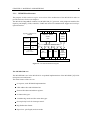
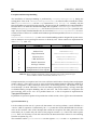
to user mode is performed without problems. Fig. 4.1 shows Topsy running on the xcopilot
emulator and the output of the shell running in user-space.
All the tools used for the port, compiler, assembler and linker and even the emulator, are available under GPL.
2. Input/Output
On the Palm, the display is used as interface between the user and the system: Input is provided
by a touch-sensitive area of the screen, and output is displayed on the same device. Purpose of
this work was to offer a minimal input/output using the serial or the infra-red interface.
A driver for the serial has been developed and output provided. Unfortunately, there are still
some problems related to the input: Data flows between the emulator to the user in both directions, but xcopilot doesn’t seem to be able to capture the incoming bytes in the appropriate
register.
An implementation of a driver for the infra-red interface couldn’t be developed because of the
lack of such a device on the emulator. The similarities between the serial and the infra-red
interface should reduce this part to a mere adaption-task.
36
CHAPTER 4. DISCUSSION AND OUTLOOK
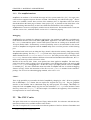
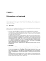
(a) Topsy
(b) Shell
Figure 4.1: Topsy running on the xcopilot emulator and the output of the shell running in user-space. If not specified, the serial output is automatically redirect by xcopilot to the console that invoked the emulator.
Using the display, some output to the user is provided by the visualisation of the logo. Because
of very early configuration of the LCD during the kernel startup phase, the appearance of the
picture can be treated as symptom of a correct initialisation of the system.
3. PalmOS applications under Topsy
Because of the availability of a very wide choice of existing software for PalmOS, possibilities
to run these applications under Topsy had to be investigated.
Unfortunately, the lack of time avoided a deep research in this direction, but a brief discussion
can be found on 4.2.2.
4.2
Outlook
The port of Topsy on Palm is only a start point for a wider use of this operating system. There are
many features of the Palm platform that can be implemented in Topsy, maybe the most interesting is
the use of the LCD display as Input/Output device.
Before adding new features to the Palm, a more robust development environment has to be created.
Besides the software emulator used in this work, xcopilot, some hardware platforms are available.
The emulator itself can be expanded in order to offer a suitable interface for debugging.
This section will give an overview of possible future enhancements of the Topsy port on Palm: Not
all proposed ideas has to be implemented, but most of them can make the use and the development of
CHAPTER 4. DISCUSSION AND OUTLOOK
37
the operating system easier.
4.2.1
Debugging
The xcopilot emulator was originally designed to run the Palm operating system, thus, the debugging
tools are designed to help the programmer to develop PalmOS applications.
During this work, the memory dump generated by xcopilot was almost the only way to have an
overview about the status of the kernel; the use of serial output was not always possible (expecially
in “critical section” such as context restoring or interrupt handling) and putting infinite loops in the
middle of the code was the only way to stop its execution.
Purpose of this section is to describe some possibilities voted to turn the debugging phase into a quick
and fast task and, thus, to make the implementation of new functionalities easier and less error-prone:
Trace: The MC68000 processor gives the possibility to set the processor in the “trace mode”
by manipulating the status register. When running in supervisor mode, it is possible to use
the assembler stop instruction. When invoked, stop advances the program counter to the
next instruction and stops the fetching and executing of instructions. A trace exception occurs
if the “T” bit of the status register was previously set to 1 (Fig. 2.2). With this method it is
possible to put breakpoints in the code and to analyse the status of the system. An interrupt
handling routine, corresponding to the vector number 9 (“Trace”, refer to Sec. 3.3.1), has to be
implemented.
A patch for xcopilot: The success of Linux leads to the idea to develop a patch for the
xcopilot emulator to help the debug of the Linux kernel. Because of its independency from
the operating system, this feature can be used to help in debugging Topsy, too. Unfortunately,
the patch is still in an early development phase, and the released alpha-version has still some
problems. The patched version of xcopilot and further informations can be found on [25].
Patching Pose: The PalmOS Emulator is the official emulator offered by Palm Inc. for developing PalmOS applications. The interesting aspect of this emulator is the possibility to
emulate even the newest models of Palm (based on the MC68EZ328), and the availability of
third-parties interfaces written with the purpose of low-level debugging [35].
Unfortunately, as the name says, Pose doesn’t emulate the whole Palm hardware, it is mostly
designed to emulate the native operating system. Because of the free availability of the source
code, it could be possible to modify Pose in order to let it emulate a real Palm.
Besides xcopilot and, eventually, pose, there are some other hardware tools that can be used as
debugging platform:
The MC68328ADS: [19] Motorola offers an Application Development System consisting in
a board with an MC68328 processor, 1MB SRAM, 1MB EPROM, a parallel and two serial
interfaces, a Windows-based debugger in boot EPROM and an LCD touch panel interface.
The M68EZ328ADS is a similar development system, the most remarkable difference is the
MC68EZ328 processor present in the newest Palm handhelds.
Simm: [36] It is a microcontroller module specifically built for the Linux operating
system. It measures an inch high, with a standard 30-pin SIMM form factor. Simm is
driven by the MC68EZ328 processor, and is equipped with 2 MB of FLASH and 8MB of
DRAM. There is also a built-in LCD panel driver capable of displaying QVGA at a resolution
of 320x240.
38
CHAPTER 4. DISCUSSION AND OUTLOOK
Its similarities with the Palm architecture (the original Linux runs on the Palm with very
few modifications) make it an interesting substitute of the Motorola development board.
4.2.2 Topsy enhancements
The LCD display
At this stage, Topsy uses the serial interface to communicate with the user. That means, a Palm
equipped with Topsy can hardly be used “on the road”.
The LCD display of the Palm is used only to display a logo, but it can be turned in a very powerful
Input/Output device: In the near future it could be possible to use the LCD display as primary output
interface and the serial can be devolved for debugging purpose. As starting point for implementing a
characters-based output on the screen, the framebuffer device of Linux can be used.
The LCD panel on the Palm provides pen input: By tapping on the screen, the and position is
determined and an IRQ is presented to the processor. Refer to [19] for more informations.
There are different implementation of handwriting recognition programs available under GPL or similar licence. An introduction to handwriting and gesture recognition is available at [37].
Xscribble [38] is an X11 application that allows a user to input characters into X11 applications, using a uni-stroke (graffiti like) alphabet. It uses the X11 test extension to allow synthesis
of characters as though they had been typed on a keyboard.
Investigation about the possibility to use Xscribble without X11 support are needed.
XMerlin [39] is a simple, small footprint, single character recognition engine for X11 based
web pads. The author affirms [40] XMerlin is very fast in analysing and recognising the characters: Approximatively 0.1 seconds/characters on a Pentium running at 133MHz. The soft is
not-adaptive, and thus not very robust: About 83% of the characters tipped by inexperienced
users were recognised, while after some training the percentage grew up to 87%
Unfortunately, XMerlin requires Xlib, thus the possibility of an implementation on Topsy has
to be investigated.
LibStroke [41] is a stroke translation library. Strokes are motions of the mouse that can be
interpreted by a program as a command and are used extensively in CAD programs. The very
simple idea behind LibStroke should lead quickly to an implementation for Topsy; even the
accuracy has proven to be quite good [42].
GridWrite [43] is based on LibStroke and uses a visible grid; characters are created by moving
the stylus between squares on the grid. Because of the presence of well-defined area for text
and number input on the Palm, this solution could be very interesting.
PalmOS emulation
The success of PalmOS has been widely determined by the availability of many applications, and
probably the end-user won’t renounce to the existing software. There are three possible methods to
permit the use of PalmOS applications with Topsy:
1. Dual-boot: The idea is to have both systems present in the Palm, and to select which one is to
use. There seem to be two main ways:
Load the Topsy kernel into RAM and execute it there. This has the advantage of retaining
PalmOS. It has the disadvantage of leaving less RAM available.
CHAPTER 4. DISCUSSION AND OUTLOOK
39
Write the kernel into the flash and execute it in place. This approach has the advantage
of maximising the use of the flash. The disadvantage is that PalmOS can’t be moved to a
different address space, so the space for Topsy may result to be insufficient.
In both cases, the idea is (after a reset-event) to let the program counter point to a small routine
that will take care to prompt to the user a menu with the choice between booting PalmOS or
Topsy.
2. Library: All the PalmOS specific functions are available in a library under Topsy. That means,
all the calls performed by Palm applications to the Palm operating system, are absolved by
Topsy. This method has the advantage to offer under Topsy a full binary compatibility (with
little overhead) to all the applications developed for the Palm. This is the approach used by
WindStone [44].
3. Virtual machine: Another possibility is to emulate the whole Palm architecture. This approach is nowaday used by vmware [45], but it could hardly be implemented with satisfactory
performances with such limited hardware resources.
4.2.3
Palm-related enhancements
The MC68328 processor combines a MC68EC000 processor with peripheral modules and system
interface logic. In this work only few components has been used: The UART for serial input/output,
the LCD controller for the logo, the enhanced real-time controller and the interrupt controller. Purpose
of this section is to give an overview about future enhancements strictly related to the processor.
UART controller: Besides the support of a serial (RS232) interface, the UART module offers
the Infra-red (IrDA) mode. The implementation should not be difficulty (a driver for the RS232
is already present), but in order to test it, it would be necessary to have Topsy running on a real
Palm.
Pulse-width modulator: The pulse-width modulator (PWM) of the MC68328 provides highquality sound generation and can also generate tones. Unfortunately, the speaker provided by
the Palm has poor quality: It is adequate for alarms but will not do, for example, DTMF (Dual
Tone Multiplexed Frequency) tones. It could be interesting to implement a sort of warningtones as the common PCs do during the boot, in order to recognise, for example, unexpected
situations.
LCD controller: Actually, only black and white picture are displayed, but the LCD controller
is capable of using up to sixteen gray levels.
Chip-select: The MC68328 processor contains eight general-purpose, programmable, chipselect signals, used for memory configuration. An interesting possibility offered by chip-select
registers, is to define memory portions as read-only or read/write.
In the future, it could be possible to implement a sort of “memory protection”, for example by
setting the kernel memory as read-only while executing user code. The resulting overhead of
such operation for each context-switch it is still not clear; further investigations are needed.
Power controller: The power controller module has three modes of operation: Normal, Doze
and Sleep that can be configured by manipulating the power control register (PCTLR).
40
CHAPTER 4. DISCUSSION AND OUTLOOK
Last word
With this thesis work, Topsy has been ported to the Palm Pilot platform. This is
could be seen as only the beginning of a wider support of Palm, because of the
potentiality of the whole project, as explained in this chapter.
Chapter 5
Acknowledgements
I would like to thank Prof. Bernhard Plattner for giving me
the opportunity to work in his group and my supervisor
Lukas Ruf for helping me in organising my work and
for constantly giving me new ideas for solving the many
problems encountered. Furthermore I would like to thank
my girlfriend Guya for the support, the Linux developing
group and Tobias Oetiker, Hubert Partl, Irene Hyna and
Elisabeth Schegl for the indispensable “The Not So Short
Introduction to LATEX 2 ”.
Un grazie speciale ai miei genitori i quali, nonostante tutto,
mi hanno sempre sostenuto: E’ stata lunga, ma
”a piccoli passi si arriva fino in cima all’Everest !”
Grazie !
Bibliography
[1] Microsoft: Pocket PC,
http://www.microsoft.com/pocketpc
[2] Palm Inc. ,
http://www.palm.com
[3] Palm Inc. : The Philosophy Behind Palm OS,
http://www.palmos.com
[4] Motorola Computer Group: MC68328 : DragonBall[tm] Integrated Microprocessor,
http://e-www.motorola.com/webapp/sps/prod cat/prod summary.jsp
?code=MC68328.
[5] G. Fankhauser, C .Conrad, E. Zitzler, B. Plattner: Topsy - A Teachable Operating System, TIK,
1997,
http://www.tik.ee.ethz.ch/ topsy
[6] Palm Inc. : The Palm OS Platform: A new form of computing,
http://www.palmos.com/platform/
[7] Motorola Computer Group: MC68EZ328: DragonBall EZ Integrated Processor,
http://e-www.motorola.com/webapp/sps/prod cat/prod summary.jsp
?code=MC68EZ328
[8] handspring: Visor,
http://www.handspring.com/
[9] Sony: CLIE handheld developers official page,
http://www.us.sonypdadev.com
[10] IBM: IBM Workpad,
www.pc.ibm.com/us/workpad
[11] Kyocera: Kyocera Smartphone Series - QCP[tm] 6035,
http://www.kyocera-wireless.com/showroom/showcase/coming soon 6000.htm
[12] Palm Inc. : Palm OS OEM Partners,
http://www.palmos.com/partner/partners.html
[13] M.Dasen:Topsy 68k, TIK, 2000.
[14] Motorola Computer Group: M68000 Family Programmer’s Reference Manual,
http://e-www.motorola.com/collateral/LIBMC68000.html
BIBLIOGRAPHY
43
[15] The EGCS steering comittee: The GNU Compiler Collection,
http://www.gnu.org/software/gcc/gcc.html
[16] B. Schmidt: The UAE Amiga Emulator,
http://www.freiburg.linux.de/ uae/
[17] Palm Inc. ,Palm OS Emulator,
http:///www.palmos.com/dev/tech/tools/emulator/
[18] Embedded Linux Microkernel Project,
www.uclinux.org
[19] Motorola Computer Group: MC68328ADS Application Development System User’s Manual,
Revision 2.0, August 1996,
http://e-www.motorola.com/collateral/MC68328ADSUM D.PDF
[20] SuSE Inc. ,SuSE Linux 7.0,
http://www.suse.com/us/products/susesoft/70news/index.html
[21] Motorola Computer Group: EC000 Core Processor (SCM68000) User’s Manual,
http://e-www.motorola.com/collateral/LIB68K.html.
[22] The XFree86 Project, Inc.TM : The XFree86TM Home Page
http://www.xfree.org
[23]
linux-xcopilot,
http://www.uclinux.org/pub/uClinux/ports/xcopilot/
[24] xcopilot-slack,
http://users.erols.com/tygris/xcopilot/
[25] Hao Tang,
http://go.163.com/ townhall/xcopilot-0.6.6.11.tar.gz
http://c3po.kc-inc.net/mail/uclinux/0893.html
[26] D. Barlow: The Linux GCC HOWTO v1.17, 28 February 1996, Chapter 3.4,
http://sunsite.unc.edu/pub/linux/docs/HOWTO/
[27] Free Software Foundation: Mirrors of www.gnu.org,
http://www.gnu.org/server/list-mirrors.html
[28] dietlibc: A static libc optimised for small size,
http://www.fefe.de/dietlibc/
[29]
Clibc: libc – C library for embedded systems,
http://cvs.uclinux.org/uClibc.html
[30] TA-HSR (Univ of Applied Sciences Rapperswil), SWITCH (Swiss Academic & Research Network), Sun Microsystems (Schweiz) AG: Swiss SunSITE,
ftp://sunsite.cnlab-switch.ch/mirror/gnu
[31] GCC FAQ,
http://www.objsw.com/CrossGCC/.
[32] Robin Miyagi: Introduction to GCC Inline Asm,
http://www.geocities.com/SiliconValley/Ridge/2544/
cprog/rmiyagi-inline-asm.txt
44
BIBLIOGRAPHY
[33] Roland H. Pesch, Jeffrey M. Osier, Cygnus Support: The GNU Binary Utilities, Chapter 4,
http://www.gnu.org
[34] The Cygwin FAQ,
http://www.cygwin.com/faq/faq toc.html
[35] EZAsm and Debug for the Palm Computing Platform, Debug,
texttthttp://www.geocities.com/ezasm/
[36] Embedded Linux/Microcontroller Project: simm
http://www.uclinux.org/ucsimm/
[37] Handwriting Recognition,
http://www.handhelds.org:8080/wiki/HandwritingRecognition
[38] Handhelds.org – Projects: X Scribble Project,
http://www.handhelds.org/projects/xscribble.html
[39] Stefan Hellkvist: XMerlin,
http://www.hellkvist.org/software/index.php3#XMerlin
[40] S. Hellkvist: On-line character recognition on small hand-held terminals using elastic matching, Department of Numerical Analysis and Computing Science, Royal Institute of Technology,
Stockholm, 1999.
[41] LibStroke Home Page: LibStroke - a stroke translation library,
http://www.etla.net/libstroke/
[42] M. Willey: Design and Implementation of a Stroke Interface Library, Department of Electrical
and Computer Engineering, Purdue University, 1997.
[43] CompanionLink Pocket Suite: GridWrite,
http://linux.companionlink.com/cpsgw.htm
[44] OSK: WindStone Structure,
http://www.oski.co.kr/windstone-structure.htm&e=814
[45] wmware: One computer, multiple worlds,
http://www.vmware.com
user.topsy
kernel.topsy
0x1040 0000
0x1020 0000
0x1010 0000
0x1000 0400
0x1000 0000
data
code
romvec
data
registers
user−data
user−code
logo
kernel−data
romvec
512K ROM
Topsy−logo
kernel−code
%sp %pc
4MB RAM
Exceptions−table
code
romvec
Kernel file
user stack
~2MB
user−data
user code
1MB
kernel stack
~1MB
kernel−data
Exceptions−table
(mirror)
0xffff ffff
0xffff f000
0x10c8 0000
0x10c0 0000
0x1040 0000
0x1000 0000
0x0000 0400
0x0000 0000
Appendix A
Overview of memory layout