1
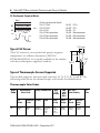
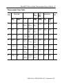
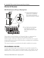
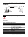
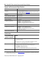
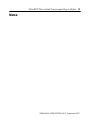
Wiring Diagrams
Micro800™ Non-isolated Thermocouple
Plug-in Module
Catalog Number 2080-TC2
http://literature.rockwellautomation.com
publication est disponible en français sous forme électronique (fichier PDF).
FR Cette
Pour la télécharger, rendez-vous sur la page Internet indiquée ci-dessus.
pubblicazione è disponibile in Italiano in formato PDF. Per scaricarla
IT Questa
collegarsi al sito Web indicato sopra.
Diese Publikation ist als PDF auf Deutsch verfügbar. Gehen Sie auf die oben
DE genannte Web-Adresse, um nach der Publikation zu suchen und sie
herunterzuladen.
publicación está disponible en español como PDF. Diríjase a la dirección web
ES Esta
indicada arriba para buscar y descarga esta publicación.
publicação está disponível em portugués como PDF. Vá ao endereço web que
PT Esta
aparece acima para encontrar e fazer download da publicação.
ZH
ZC
KO
2 Micro800™ Non-isolated Thermocouple Plug-in Module
Environment and Enclosure
ATTENTION
This equipment is intended for use in a Pollution Degree 2 industrial
environment, in overvoltage Category II applications (as defined in IEC
60664-1), at altitudes up to 2000 m (6562 ft) without derating. This equipment
is considered Group 1, Class A industrial equipment according to IEC/CISPR
11. Without appropriate precautions, there may be difficulties with
electromagnetic compatibility in residential and other environments due to
conducted and radiated disturbances.
This equipment is supplied as open-type equipment. It must be mounted
within an enclosure that is suitably designed for those specific environmental
conditions that will be present and appropriately designed to prevent personal
injury resulting from accessibility to live parts. The enclosure must have
suitable flame-retardant properties to prevent or minimize the spread of flame,
complying with a flame spread rating of 5V A, V2, V1, V0 (or equivalent) if
non-metallic. The interior of the enclosure must be accessible only by the use
of a tool. Subsequent sections of this publication may contain additional
information regarding specific enclosure type ratings that are required to
comply with certain product safety certifications.
In addition to this publication, see:
• Industrial Automation Wiring and Grounding Guidelines, Rockwell
Automation publication 1770-4.1, for additional installation
requirements.
• NEMA Standard 250 and IEC 60529, as applicable, for explanations of
the degrees of protection provided by different types of enclosure.
Preventing Electrostatic Discharge
ATTENTION
This equipment is sensitive to electrostatic discharge, which can cause
internal damage and affect normal operation. Follow these guidelines when
you handle this equipment:
• Touch a grounded object to discharge potential static.
• Wear an approved grounding wriststrap.
• Do not touch connectors or pins on component boards.
• Do not touch circuit components inside the equipment.
• Use a static-safe workstation, if available.
• Store the equipment in appropriate static-safe packaging when not in
use.
Publication 2080-WD006A-EN-P - September 2011
Micro800™ Non-isolated Thermocouple Plug-in Module 3
North American Hazardous Location Approval
The following modules are North American Hazardous Location approved:
2080-TC2
The following information applies
when operating this equipment in
hazardous locations:
Informations sur l’utilisation de cet
équipement en environnements dangereux:
Products marked "CL I, DIV 2, GP A, B, C, D" are
suitable for use in Class I Division 2 Groups A,
B, C, D, Hazardous Locations and nonhazardous
locations only. Each product is supplied with
markings on the rating nameplate indicating the
hazardous location temperature code. When
combining products within a system, the most
adverse temperature code (lowest "T" number)
may be used to help determine the overall
temperature code of the system. Combinations
of equipment in your system are subject to
investigation by the local Authority Having
Jurisdiction at the time of installation.
Les produits marqués "CL I, DIV 2, GP A, B, C, D" ne
conviennent qu'à une utilisation en environnements de
Classe I Division 2 Groupes A, B, C, D dangereux et non
dangereux. Chaque produit est livré avec des marquages
sur sa plaque d'identification qui indiquent le code de
température pour les environnements dangereux.
Lorsque plusieurs produits sont combinés dans un
système, le code de température le plus défavorable
(code de température le plus faible) peut être utilisé
pour déterminer le code de température global du
système. Les combinaisons d'équipements dans le
système sont sujettes à inspection par les autorités
locales qualifiées au moment de l'installation.
WARNING
EXPLOSION HAZARD
AVERTISSEMENT
•
Do not disconnect
equipment unless power
has been removed or the
area is known to be
nonhazardous.
•
Do not disconnect
connections to this
equipment unless power
has been removed or the
area is known to be
nonhazardous. Secure any
external connections that
mate to this equipment by
using screws, sliding
latches, threaded
connectors, or other means
provided with this product.
•
Substitution of any
component may impair
suitability for Class I,
Division 2.
•
If this product contains
batteries, they must only be
changed in an area known
to be nonhazardous.
RISQUE D’EXPLOSION
•
Couper le courant ou s'assurer
que l'environnement est
classé non dangereux avant de
débrancher l'équipement.
•
Couper le courant ou s'assurer
que l'environnement est
classé non dangereux avant de
débrancher les connecteurs.
Fixer tous les connecteurs
externes reliés à cet
équipement à l'aide de vis,
loquets coulissants,
connecteurs filetés ou autres
moyens fournis avec ce
produit.
•
La substitution de tout
composant peut rendre cet
équipement inadapté à une
utilisation en environnement
de Classe I, Division 2.
•
S'assurer que l'environnement
est classé non dangereux
avant de changer les piles.
Publication 2080-WD006A-EN-P - September 2011
4 Micro800™ Non-isolated Thermocouple Plug-in Module
Parts List
Your package contains one Micro800 Non-isolated Thermocouple plug-in
module, two module fastening screws, one trimmed/formed bendable lead
NTC thermistor and these pin out guide wiring instructions.
45010
You can choose to wire the plug-in before inserting it onto the controller, or
wire it once the module is secured in place.
ATTENTION
• This equipment is considered Group 1, Class A industrial equipment
according to IEC/CISPR 11. Without appropriate precautions, there may be
difficulties with electromagnetic compatibility in residential and other
environments due to conducted and radiated disturbance.
• Be careful when stripping wires. Wire fragments that fall into the controller
could cause damage. Once wiring is complete, make sure the controller is
free of all metal fragments.
• Do not wire more than 2 conductors on any single terminal.
• If you insert or remove the plug-in module while power is on, an electrical
arc can occur. This could cause an explosion in hazardous location
installations. Be sure that power is removed or the area is nonhazardous
before proceeding.
• Use shielded twisted core cables to connect the sensor.
• The shield should be grounded only at controller end.
• Connect the thermocouples directly to the module.
• Do not insert or remove the plug-in module while power is applied,
otherwise, permanent damage to equipment may occur.
Publication 2080-WD006A-EN-P - September 2011
Micro800™ Non-isolated Thermocouple Plug-in Module 5
Insert Module into Controller
Follow the instructions to insert and secure the plug-in module to the
controller.
44012
ATTENTION
This plug-in module is intended for use with Micro800 Family of
Programmable Controllers.
1. Position the plug-in module with the terminal block facing the front
of the controller as shown.
2. Snap the module into the module bay.
3. Using a screwdriver, tighten the 10…12 mm (0.39…0.47 in.) M3 self
tapping screw to torque specifications.
Wire the Module
Follow the pinout diagram to wire your plug-in module.
Publication 2080-WD006A-EN-P - September 2011
6 Micro800™ Non-isolated Thermocouple Plug-in Module
12-Pin Female Terminal Block
Back
B
1
2
3
4
5
6
A
1
2
3
4
5
6
B1 +
40511
Front
B1 A1 +
A2 -
CH1
(View into terminal block)
Pin A1 CH0+
Pin A2 CH0Pin A3 CJ+
Pin A4 No connection
Pin A5 No connection
Pin A6 No connection
Pin B1
Pin B2
Pin B3
Pin B4
Pin B5
Pin B6
CH1+
CH1CJNo connection
No connection
No connection
CH2
2.41 max
Type of CJC Sensor
The CJC sensor is a non-polarized, passive negative
temperature co-efficient thermistor (EPCOS
B57869S0502F140). It is readily available in the market
with most third party suppliers/vendors.
6.5 max
0.25
50 ± 2
Types of Thermocouple Sensors Supported
The module supports thermocouple sensors J, K, N, T, E, R, S, and B. The
following table shows the thermocouple color codes for identification.
Thermocouple Color Codes
ANSI
Code
J
ANSI MC 96.1
Color Code
Alloy Combination
T/C
Grade
Extension +Lead
Grade
+White
-Red
+White
-Red
-Lead
IRON Fe
Constantan
(magnetic) CopperNickel
Cu-Ni
Max
T/C
Grade
EMF
(mV)
Over
Max
IEC 584.3
Color Coding
Temp
Range
Temp
Range
T/C
Grade
Intrinsically
Safe
-210…
1200 °C
-346…
2193 °F
-6.095…
59.563
+Black
-White
+Black
-White
Publication 2080-WD006A-EN-P - September 2011
IEC
Code
J
Micro800™ Non-isolated Thermocouple Plug-in Module 7
Thermocouple Color Codes
ANSI
Code
ANSI MC 96.1
Color Code
Alloy Combination
Max
T/C
Grade
EMF
(mV)
Over
Max
IEC 584.3
Color Coding
IEC
Code
T/C
Grade
Extension +Lead
Grade
-Lead
Temp
Range
Temp
Range
T/C
Grade
Intrinsically
Safe
K
+Yellow
-Red
+Yellow
-Red
Chromega
NickelChromium
Ni-Cr
Alomega
Nickel
Aluminum
Ni-Al
(magnetic)
-270…
1372 °C
-454…
2501 °F
-6.458…
54.886
+Green
-White
+Green
-White
K
T
+Blue
-Red
+Blue
-Red
Copper
Cu
Constantan
CopperNickel
Cu-Ni
-270…
400 °C
-454…
752 °F
-6.258…
20.872
+Brown
-White
+Brown
-White
T
E
+Purple
-Red
+Purple
-Red
Chromega
NickelChromium
Ni-Cr
Constantan
CopperNickel
Cu-Ni
-270…
1000 °C
-454…
1832 °F
-9.835…
76.373
+Purple
-White
+Purple
-White
E
N
+Orange
-Red
+Orange
-Red
Omega-P
Nicrosil
Ni-Cr-Si
Omega-N
Nisil
Ni-Si-Mg
-270…
1300 °C
-450…
2372 °F
-4.345…
47.513
+Pink
-White
+Pink
-White
N
R
None
+Black
Established -Red
Platinum- Platinum
13%
Pt
Rhodium
Pt-13% Rh
-50…
1768 °C
-58…
3214 °F
-0.226…
21.101
+Orange
-White
+Orange
-White
R
S
None
+Black
Established -Red
Platinum- Platinum
10%
Pt
Rhodium
Pt-10% Rh
-50…
1768 °C
-58…
3214 °F
-0.236…
18.693
+Orange
-White
+Orange
-White
S
B
None
+Gray
Established -Red
Platinum- Platinum30%
6% Rhodium
Rhodium Pt-6% Rh
Pt-30% Rh
0…
1820 °C
32…
3308 °F
0…
13.820
+Gray
-White
+Gray
-White
B
Publication 2080-WD006A-EN-P - September 2011
8 Micro800™ Non-isolated Thermocouple Plug-in Module
Wire the CJC Thermistor
2080-TC2 CJC Thermistor Wiring and Mounting Guide
2.41 max
1. Connect the thermocouples to
channel 0 and 1, respectively.
Then, connect and screw the
thermistor to terminals A3 and B3.
6.5 max
0.25
mm
50 ± 2
5 mm
B3
5 mm
A3
B3
2. Once fitted, bend the black bead
of the thermistor such that it
makes contact with the A2 screw
securely.
A3
The position for the thermistor, as illustrated, helps to compensate for
thermoelectric voltages developed at screw junction equally for
thermocouples connected to channels 0 and 1. If the bead is not in proper
contact with the screw, there will be deviation in readings due to inadequate
isothermal compensation.
This sensor is passive, non-polarized and readily available in the market.
Wire the Module in the Field
Connect the thermocouple sensors directly to the module terminals. If a
separate cable is used to connect the thermocouple to the module, the CJC
thermistor has to be mounted to the cable at thermocouple junction only.
Publication 2080-WD006A-EN-P - September 2011
Micro800™ Non-isolated Thermocouple Plug-in Module 9
Direct sensor wiring
Shielded/sheathed thermocouple sensor
2080-TC2
Blue Red
+
Red
-
Blue
Process
temperature
measurement
1 2 3
4 5 6
1 2 3
4 5 6
45790
ATTENTION
Direct wiring is the preferred method of wiring for thermocouples.
Specifications
General and Environmental Specifications
Attribute
Value
Mounting torque
0.2 Nm (1.48 lb-in.)
Terminal screw torque
0.22…0.25 Nm (1.95…2.21 lb-in.)
using a 2.5 mm [0.10 in.] flat-blade screwdriver
Wire size
0.14…1.5 mm2 (26…16 AWG) solid copper wire or
0.14…1.0 mm2 (26…17 AWG) stranded copper wire
rated @ 90 °C (194 °F ) insulation max
Input impedance
> 300 KΩ
Common mode rejection ratio
100 dB @ 50/60 Hz
Normal mode rejection ratio
70 dB @ 50/60 Hz
Resolution
14-bit
Publication 2080-WD006A-EN-P - September 2011
10 Micro800™ Non-isolated Thermocouple Plug-in Module
General and Environmental Specifications
Attribute
Value
Accuracy
±1.0 °C for TC @ 25 °C (77 °F)
For more information, see the Micro830 Programmable Controllers
User Manual, publication 2080-UM002.
Channels
2, non-isolated
Thermocouple types supported
J,K,N,T,E,R,S,B
Open-circuit detection time
8…1515 ms
Power consumption
3.3 V, 40 mA
Temperature, operating
IEC60068-2-1 (Test Ad, Operating Cold),
IEC60068-2-2, (Test Bd, Operating Dry Heat),
IEC 60068-2-14 (Test Nb, Operating Thermal Shock):
-20...65 °C (-4…149 °F)
Temperature, surrounding air, max.
65 °C (149 °F)
Temperature, non-operating
IEC60068-2-1 (Test Ad, Operating Cold),
IEC60068-2-2, (Test Bd, Operating Dry Heat),
IEC 60068-2-14 (Test Nb, Operating Thermal Shock):
-40...85 °C (-40…185 °F)
North American temp code
T4
Certifications
Certification (when
Value
product is marked)(1)
c-UL-us
UL Listed Industrial Control Equipment, certified for US and Canada.
See UL File E322657.
UL Listed for Class I, Division 2 Group A,B,C,D Hazardous Locations,
certified for U.S. and Canada. See UL File E334470.
CE
European Union 2004/108/EC EMC Directive, compliant with:
EN 61326-1; Meas./Control/Lab., Industrial Requirements
EN 61000-6-2; Industrial Immunity
EN 61000-6-4; Industrial Emissions
EN 61131-2; Programmable Controllers (Clause 8, Zone A & B)
C-Tick
Australian Radiocommunications Act, compliant with:
AS/NZS CISPR 11; Industrial Emissions
(1)
See the Product Certification link at http://www.ab.com for Declarations of Conformity, Certificates,
and other certification details.
Publication 2080-WD006A-EN-P - September 2011
Micro800™ Non-isolated Thermocouple Plug-in Module 11
Notes:
Publication 2080-WD006A-EN-P - September 2011
Rockwell Automation Support
Rockwell Automation provides technical information on the Web to assist you in using its products. At
http://www.rockwellautomation.com/support/, you can find technical manuals, a knowledge base of FAQs,
technical and application notes, sample code and links to software service packs, and a MySupport feature
that you can customize to make the best use of these tools.
For an additional level of technical phone support for installation, configuration and troubleshooting, we
offer TechConnect support programs. For more information, contact your local distributor or Rockwell
Automation representative, or visit http://www.rockwellautomation.com/support/.
Installation Assistance
If you experience a problem within the first 24 hours of installation, please review the information that's
contained in this manual. You can also contact a special Customer Support number for initial help in getting
your product up and running.
United States or Canada
1.440.646.3434
Outside United States or
Canada
Use the Worldwide Locator at
http://www.rockwellautomation.com/support/americas/phone_en.html, or
contact your local Rockwell Automation representative.
New Product Satisfaction Return
Rockwell Automation tests all of its products to ensure that they are fully operational when shipped from
the manufacturing facility. However, if your product is not functioning and needs to be returned, follow
these procedures.
United States
Contact your distributor. You must provide a Customer Support case number
(call the phone number above to obtain one) to your distributor to complete
the return process.
Outside United States
Please contact your local Rockwell Automation representative for the return
procedure.
Documentation Feedback
Your comments will help us serve your documentation needs better. If you have any suggestions on how to
improve this document, complete this form, publication RA-DU002, available at
http://www.rockwellautomation.com/literature/.
Allen-Bradley, Rockwell Automation, MicroLogix, and TechConnect are trademarks of Rockwell Automation, Inc.
Trademarks not belonging to Rockwell Automation are property of their respective companies.
Publication 2080-WD006A-EN-P - September 2011
PN 953203-26(01)
Copyright © 2011 Rockwell Automation, Inc. All rights reserved.