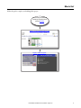
1
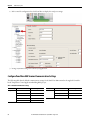
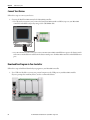
Quick Start Controller-based Temperature Control Application Building Block Connected Components Accelerator Toolkit Important User Information Read this document and the documents listed in the additional resources section about installation, configuration, and operation of this equipment before you install, configure, operate, or maintain this product. Users are required to familiarize themselves with installation and wiring instructions in addition to requirements of all applicable codes, laws, and standards. Activities including installation, adjustments, putting into service, use, assembly, disassembly, and maintenance are required to be carried out by suitably trained personnel in accordance with applicable code of practice. If this equipment is used in a manner not specified by the manufacturer, the protection provided by the equipment may be impaired. In no event will Rockwell Automation, Inc. be responsible or liable for indirect or consequential damages resulting from the use or application of this equipment. The examples and diagrams in this manual are included solely for illustrative purposes. Because of the many variables and requirements associated with any particular installation, Rockwell Automation, Inc. cannot assume responsibility or liability for actual use based on the examples and diagrams. No patent liability is assumed by Rockwell Automation, Inc. with respect to use of information, circuits, equipment, or software described in this manual. Reproduction of the contents of this manual, in whole or in part, without written permission of Rockwell Automation, Inc., is prohibited. Throughout this manual, when necessary, we use notes to make you aware of safety considerations. WARNING: Identifies information about practices or circumstances that can cause an explosion in a hazardous environment, which may lead to personal injury or death, property damage, or economic loss. ATTENTION: Identifies information about practices or circumstances that can lead to personal injury or death, property damage, or economic loss. Attentions help you identify a hazard, avoid a hazard, and recognize the consequence. IMPORTANT Identifies information that is critical for successful application and understanding of the product. Labels may also be on or inside the equipment to provide specific precautions. SHOCK HAZARD: Labels may be on or inside the equipment, for example, a drive or motor, to alert people that dangerous voltage may be present. BURN HAZARD: Labels may be on or inside the equipment, for example, a drive or motor, to alert people that surfaces may reach dangerous temperatures. ARC FLASH HAZARD: Labels may be on or inside the equipment, for example, a motor control center, to alert people to potential Arc Flash. Arc Flash will cause severe injury or death. Wear proper Personal Protective Equipment (PPE). Follow ALL Regulatory requirements for safe work practices and for Personal Protective Equipment (PPE). Allen-Bradley, Connected Components Workbench, Micro800, Micro830, Micro850, PanelView, PowerFlex, Stratix, Rockwell Automation, and Rockwell Software are trademarks of Rockwell Automation, Inc. Trademarks not belonging to Rockwell Automation are property of their respective companies. Where to Start Follow this path to complete your building block project. Read the Getting Started CCAT with System Design Assistant Quick Start, publication CC-QS035. Chapter 1 - Set Up a Temperature Control System Chapter 2 - Validate Your System Rockwell Automation Publication CC-QS028C-EN-P - August 2015 3 Where to Start Notes: 4 Rockwell Automation Publication CC-QS028C-EN-P - August 2015 Table of Contents Preface About This Publication. . . . . . . . . . . . . . . . . . . . . . . . . . . . . . . . . . . . . . . . . . . . . 7 Terminology. . . . . . . . . . . . . . . . . . . . . . . . . . . . . . . . . . . . . . . . . . . . . . . . . . . . . . . 8 Available Connected Components Accelerator Toolkits . . . . . . . . . . . . . . 9 Additional Resources . . . . . . . . . . . . . . . . . . . . . . . . . . . . . . . . . . . . . . . . . . . . . . . 9 Chapter 1 Set Up a Temperature Control System Before You Begin . . . . . . . . . . . . . . . . . . . . . . . . . . . . . . . . . . . . . . . . . . . . . . . . 11 What You Need . . . . . . . . . . . . . . . . . . . . . . . . . . . . . . . . . . . . . . . . . . . . . . . . . Follow These Steps . . . . . . . . . . . . . . . . . . . . . . . . . . . . . . . . . . . . . . . . . . . . . . . Select Your Controller and Determine Your Control Output Mode . . . Analog Control Mode . . . . . . . . . . . . . . . . . . . . . . . . . . . . . . . . . . . . . . . . PWM Control Mode . . . . . . . . . . . . . . . . . . . . . . . . . . . . . . . . . . . . . . . . . Select and Configure Your Temperature Sensor . . . . . . . . . . . . . . . . . . . . Wire Your Temperature Control System. . . . . . . . . . . . . . . . . . . . . . . . . . . 11 12 12 12 15 17 23 Chapter 2 Validate Your System Before You Begin . . . . . . . . . . . . . . . . . . . . . . . . . . . . . . . . . . . . . . . . . . . . . . . . What You Need . . . . . . . . . . . . . . . . . . . . . . . . . . . . . . . . . . . . . . . . . . . . . . . . . Follow These Steps . . . . . . . . . . . . . . . . . . . . . . . . . . . . . . . . . . . . . . . . . . . . . . . Review the System Overview . . . . . . . . . . . . . . . . . . . . . . . . . . . . . . . . . . . . . . Configure the Micro800 Controller Serial Port . . . . . . . . . . . . . . . . . . . . . Configure PanelView 800 Terminal Communication Settings . . . . . . . Connect Your Devices. . . . . . . . . . . . . . . . . . . . . . . . . . . . . . . . . . . . . . . . . . . . Download Your Program to Your Controller. . . . . . . . . . . . . . . . . . . . . . . Configure the IP Address for Your PanelView 800 Terminal . . . . . . . . Transfer Your HMI Application to Your PanelView 800 Terminal . . . . Validate Your System. . . . . . . . . . . . . . . . . . . . . . . . . . . . . . . . . . . . . . . . . . . . . Understand the Machine Functions Screen . . . . . . . . . . . . . . . . . . . . . Main Control Screen . . . . . . . . . . . . . . . . . . . . . . . . . . . . . . . . . . . . . . . . . Settings Screen . . . . . . . . . . . . . . . . . . . . . . . . . . . . . . . . . . . . . . . . . . . . . . . Manual Tune Screen. . . . . . . . . . . . . . . . . . . . . . . . . . . . . . . . . . . . . . . . . . Auto Tune Screen . . . . . . . . . . . . . . . . . . . . . . . . . . . . . . . . . . . . . . . . . . . . AT (Auto Tune) Parameters Screen. . . . . . . . . . . . . . . . . . . . . . . . . . . . Fault Screen. . . . . . . . . . . . . . . . . . . . . . . . . . . . . . . . . . . . . . . . . . . . . . . . . . Test the Manual Control Mode . . . . . . . . . . . . . . . . . . . . . . . . . . . . . . . Test the Auto Tune Mode . . . . . . . . . . . . . . . . . . . . . . . . . . . . . . . . . . . . Test the Auto Control Mode . . . . . . . . . . . . . . . . . . . . . . . . . . . . . . . . . . Rockwell Automation Publication CC-QS028C-EN-P - August 2015 27 27 28 28 29 30 32 32 34 35 36 36 37 38 39 40 41 42 43 44 45 5 Table of Contents Appendix A PID Temperature Control Userdefined Function Blocks RA_IPID_TEMPCONTROLLER User-defined Function Block . . . . . 47 RA_IPID_TEMPCONTROLLER User-defined Function Block (UDFB) Operation. . . . . . . . . . . . . . . . . . . . . . . . . . . . . . . . . . . . . . . . . . . . . . . 51 Appendix B Global Variables 6 . . . . . . . . . . . . . . . . . . . . . . . . . . . . . . . . . . . . . . . . . . . . . . . . . . . . . . . . . . . . . . . . . 53 Rockwell Automation Publication CC-QS028C-EN-P - August 2015 Preface About This Publication This quick start is designed to provide a way to implement common control tasks by aiding in the selection of products and providing access to panel and wiring information. Each section is designed with a different task as a standalone machine, or implemented in a larger system. IMPORTANT Use this publication together with other Connected Components Accelerator Toolkit quick starts to aid in building your Micro800™ based application. Refer to Available Connected Components Accelerator Toolkits on page 9 for where to find other quick starts. To help with the design and installation of your system, application files and other information are provided on the Connected Components Accelerator Toolkit (CCAT). The CCAT provides bills of materials (BOM), CAD drawings for panel layout and wiring, control programs, Human Machine Interface (HMI) screens, and more. With these tools and the built-in best-practices design, you are free to focus on the design of your machine control and not on design overhead tasks. The CCAT is available on the Connected Components Accelerator Toolkit DVD, publication CC-QR002, or through the Rockwell Automation® Software Download and Registration System (SDRS) at http://www.rockwellautomation.com/rockwellautomation/products-technologies/connected-components/tools/ accelerator-toolkit.page. The beginning of each chapter contains the following information. Read these sections carefully before you begin work in each chapter: • Before You Begin - The chapters in this quick start do not have to be completed in the order in which they appear. However, this section defines the minimum amount of preparation that is required before completing the current chapter. • What You Need - This section lists the tools that are required to complete the steps in the current chapter, including, but not limited to, hardware and software. • Follow These Steps - This section illustrates the steps in the current chapter and identifies the steps that are required to complete the examples. Rockwell Automation Publication CC-QS028C-EN-P - August 2015 7 Preface Terminology 8 Term (abbreviation) Definition Application Sequence Programs User-modified programs that work together with the standard state machine logic to control what the machine does while in the abort, clear, reset, run, and stop states. Auto/manual operation When the PanelView™ 800 terminal is in Auto mode, the controller logic controls the machine and monitors machine status. When the PanelView 800 terminal switches to Manual mode, the terminal takes over control. Command buttons and numeric entry fields are available only when the machine is in Manual mode. Bill of Materials (BOM) A list of components that are needed for your system. Building block (BB) Tools to accelerate and simplify the development of a Micro800 controller-based application. A typical building block includes a starting Bill of Material (BOM), Computer-Aided Design (CAD) drawings, Micro800 controller programs, PanelView 800 terminal applications, and a quick start document. Computer-Aided Design (CAD) A computer-based system that is developed to facilitate design of mechanical parts. Connected Components Accelerator Toolkit (CCAT) Software with application files and other information to speed the design and startup of component-based machines. CCAT project A project that consists of these items: • A ProposalWorks™-based bill of materials • A set of CAD drawings (dimensions and schematics) • A Connected Components Workbench project • HMI screens • A set of Quick Start documents • A project document with information about the project components and links to reference materials Connected Components Workbench™ software Software environment to configure or program Micro800 controllers, PanelView 800 terminals, PowerFlex® drives, and other component-level products. Connected Components Workbench project A project that consists of one or more of these items: • Micro800 controller configuration • Up to 256 Micro800 programs, each with program local variables • Micro800 global variables • PanelView 800 terminal application • PowerFlex drive parameter lists Global variables Project variables that any program can access, which includes all I/O and system variables. State Machine control code Machine logic to coordinate overall machine operation that is based on states. The state machine broadcasts commands and receives feedback information from each of the building blocks via user-modified application sequence programs. Tags A PanelView 800 term for variables. User-defined Function Blocks (UDFBs) Function block instructions that can be used like standard function block instructions within any Connected Components Workbench programming language. Anyone who uses Connected Components Workbench software can write these functions blocks. Many UDFBs are posted on the Rockwell Automation sample code website: http://samplecode.rockwellautomation.com/idc/groups/public/documents/webassets/sc_home_page.hcst. User-defined Object (UDO) A collection of PanelView 800 terminal screen objects that can be pasted into a new screen. Rockwell Automation Publication CC-QS028C-EN-P - August 2015 Preface Available Connected Components Accelerator Toolkits For the most up-to-date listing of available Connected Components Accelerator Toolkits and related quick starts, refer to these resources: • Rockwell Automation Connected Components Accelerator Toolkit website at http://www.rockwellautomation.com/rockwellautomation/products-technologies/connected-components/tools/ accelerator-toolkit.page • Connected Components Accelerator Toolkit Building Block Project Descriptions Quick Reference, publication CC-QR003 Additional Resources These resources contain information about related products from Rockwell Automation. Resource Description Micro820™ 20-point Programmable Controllers User Manual, publication 2080-UM005 Provides a reference guide for Micro820 controller systems. It also contains procedures to install, wire, and troubleshoot your controller. Micro830™ and Micro850™ Programmable Controllers User Manual, publication 2080-UM002 Provides information to install, wire, and troubleshoot the Micro830 and Micro850 programmable controllers. Micro800 Digital and Analog Plug-in Modules and Accessories User Manual, publication 2080-UM004 Provides information to install, wire, and troubleshoot Micro800 plug-in modules and accessories. PanelView 800 HMI Terminals Installation Instructions, publication 2711R-IN001 Provides information to install, wire, ground, and troubleshoot PanelView 800 HMI terminals. PanelView 800 HMI Terminals User Manual, publication 2711R-UM001 Provides information to configure, operate, and troubleshoot the PanelView 800 HMI terminals. You can view or download publications at http://www.rockwellautomation.com/literature. To order paper copies of technical documentation, contact your local Allen-Bradley distributor or Rockwell Automation sales representative. Rockwell Automation Publication CC-QS028C-EN-P - August 2015 9 Preface Notes: 10 Rockwell Automation Publication CC-QS028C-EN-P - August 2015 Chapter 1 Set Up a Temperature Control System This chapter guides you through setting up a temperature control system with a Micro800 controller that uses the supplied device-building block sample code. The sample code can accept a wide range of temperature sensor input, as well as provide analog and Pulse Width Modulation (PWM) control output to suit your application needs. Micro850 controllers are referenced throughout this document. Wherever a Micro850 controller is referenced, a Micro820 or Micro830 controller can also be used. Before You Begin Review the Getting Started CCAT with System Design Assistant, publication CC-QS035. What You Need • • • • • • • • Windows-based personal computer with Internet access Connected Components Workbench software, version 6 or later Micro800 controller (transistor output type preferred) Supported temperature sensor Heating or cooling device Thermocouple or RTD plug-ins Analog output plug-ins (for analog control) USB programming cable (A to B) for personal computer to Micro800 communication Rockwell Automation Publication CC-QS028C-EN-P - August 2015 11 Chapter 1 Set Up a Temperature Control System Follow These Steps Follow these steps to configure your Controller-based Temperature Control Application Building Block. Start Select Your Controller and Determine Your Control Output Mode on page 12 Select and Configure Your Temperature Sensor on page 17 Wire Your Temperature Control System on page 23 Select Your Controller and Determine Your Control Output Mode Depending on your application, you can use analog or PWM Control. The sample code is designed for both control modes. We recommend that you use a transistor output type controller if you prefer PWM Control mode. Analog Control Mode Follow these steps if analog is your preferred control mode; see page 15 if PWM is your preferred control mode. 1. Start the supplied IPID Temperature Controller Building Block project for your specific Micro800 controller with the Connected Component Workbench software. If necessary, use controller type change to match your Micro800 controller catalog number. Refer to the software help for instructions on controller type change. 2. In your Project Organizer, double-click the Micro800 controller icon to launch the controller configuration screen. This examples shows a Micro850 controller. 12 Rockwell Automation Publication CC-QS028C-EN-P - August 2015 Set Up a Temperature Control System Chapter 1 The Controller Detail view appears in the main project window. By default, an analog output plug-in (2080-OF2) has been configured for you in slot 1. ATTENTION: When a project is created with the CCAT generation function, no plug-in module is configured. You must add and configure the plug-in manually. Refer to the default configuration described in the following steps. 3. Click slot 1. 4. From the Channel 0 Output Type pull-down menu, choose the analog output type for your application. 5. From the Channel 0 Output State pull-down menu, choose Enabled. Rockwell Automation Publication CC-QS028C-EN-P - August 2015 13 Chapter 1 Set Up a Temperature Control System 6. In your Project Organizer, double-click TC_01. ATTENTION: When a project is created with the CCAT generation function, the program name is ‘Device name’, which you define. 7. In rung 1, delete the MOV instruction for Out_PWM. 8. Determine the analog output to control your heating or cooling device. In rung 1, either keep the default analog output variable _IO_P1_AO_00 or click the variable to choose another one. ATTENTION: When a project is created with the CCAT generation function, the terminal selection is blank. You must select the analog output terminal via the pull-down menu. 14 Rockwell Automation Publication CC-QS028C-EN-P - August 2015 Set Up a Temperature Control System Chapter 1 PWM Control Mode Follow these steps if PWM is your preferred control mode. IMPORTANT Use a transistor output-type controller if you use PWM Control mode. 1. Start the supplied IPID Temperature Controller Building Block project for your specific Micro800 controller with the Connected Component Workbench software. If necessary, use controller type change to match your Micro800 controller catalog number. Refer to the software help for instructions on how to change the controller type. 2. In your Project Organizer, double-click the Micro800 controller icon to launch the controller configuration screen. The Controller Detail view appears in the main project window. ATTENTION: When a project is created with the CCAT generation function, no plug-in is configured. Therefore, you can skip step 3. 3. Use the following steps to change the default analog output plug-in module (2080-OF2) for slot 1. a. Click slot 1. b. Right-click slot 1 and choose Delete. Rockwell Automation Publication CC-QS028C-EN-P - August 2015 15 Chapter 1 Set Up a Temperature Control System 4. In your Project Organizer, double-click TC_01. ATTENTION: When a project is created with the CCAT generation function, the program name is ‘Device name’, which you define. 5. In rung 1, delete the MOV instruction for Out_Analog. 6. Determine the digital output for PWM to control your heating or cooling device. In rung 1, either keep the default digital output variable _IO_EM_DO_02 or click the variable to choose another one. ATTENTION: When a project is created with the CCAT generation function, the terminal selection is blank. You must select the digital output terminal via the pull-down menu. 16 Rockwell Automation Publication CC-QS028C-EN-P - August 2015 Set Up a Temperature Control System Chapter 1 Select and Configure Your Temperature Sensor You are expected to have configured your control output from the previous section. Two temperature sensor plug-ins are available for Micro800 controllers, catalog numbers 2080-TC2 and 2080-RTD2. You typically need only one temperature sensor for each control output type and for each temperature sensor plug-in. In this section, you select the type of temperature sensor and plug-in suitable for your application. 2080-TC2 Plug-in Use the following table as reference if you are using a thermocouple-type temperature sensor. Table 1 - Thermocouple Sensor Types and Temperature Ranges Thermocouple Type Temperature Range °C (°F) Accuracy °C (°F) Min Max ±1.0 °C (°F) ±3.0 °C (°F) B 40 (104) 1820 (3308) 90…1700 (194…3092) < 90 (< 194) > 1700 (> 3092) E -270 (-454) 1000 (1832) -200…930 (-328…1706) < -200 (< -328) > 930 (> 1706) J -210 (-346) 1200 (2192) -130…1100 (-202…2012) < -130 (< -202) > 1100 (> 2012) K -270 (-454) 1370 (2498) -200…1300 (-328…2372) < -200 (< -328) > 1300 (> 2372) N -270 (-454) 1300 (2372) -200…1200 (-328…2192) < -200 (< -328) > 1200 (> 2192) R -50 (-58) 1760 (3200) 40…1640 (104…2984) < 40 (< 104) > 1640 (> 2984) S -50 (-58) 1760 (3200) 40…1640 (104…2984) < 40 (< 104) > 1640 (> 2984) T -270 (-454) 400 (752) -220…340 (-364…644) < -220 (< -364) > 340 (> 644) ADC Update Rate in Hz (Accuracy °C) 4.17, 6.25, 10, 16.7 (±1.0) 19.6, 33, 50, 62, 123, 242, 470 (±3.0) Follow these steps to select a thermocouple-type temperature sensor for your Controller-based Temperature Control Application Building Block project. 1. In your Project Organizer, double-click the Micro800 controller icon to launch the controller configuration screen. The Controller Detail view appears in the main project window. ATTENTION: When a project is created with the CCAT generation function, no plug-in module is configured. You must add and configure the plug-in manually. Refer to the default configuration described in the following steps. Rockwell Automation Publication CC-QS028C-EN-P - August 2015 17 Chapter 1 Set Up a Temperature Control System 2. Use the following steps to change the default plug-in module (2080-RTD2) for slot 2. a. Click slot 2. b. Right-click slot 2 and choose 2080-TC2. 3. From the Channel 0 Thermocouple Type pull-down menu, choose the thermocouple type for your application. 4. From the Channel 0 Data Update Rate pull-down menu, choose the data update rate for your application. 18 Rockwell Automation Publication CC-QS028C-EN-P - August 2015 Set Up a Temperature Control System Chapter 1 5. In your Project Organizer, double-click TC_01. ATTENTION: When a project is created with the CCAT generation function, the program name is ‘Device name’, which you define. 6. In rung 2, either keep the default variables _IO_P2_AI_00 and _IO_P2_AI_02 or click each variable for other choices. ATTENTION: When a project is created with the CCAT generation function, these terminal selections are blank. You must select the analog input terminals via the pull-down menus. Each temperature sensor input consists of two analog values, which are temperature feedback and sensor status. These values must be paired so the sensor status properly represents the temperature feedback measurement. Example: _IO_Px_AI_00 measures the temperature value for input 1 and _IP_Px_AI_02 indicates sensor status. Therefore: _IO_Px_AI_00 must be paired with _IP_Px_AI_02 and _IO_Px_AI_01 must be paired with _IP_Px_AI_03 Sensor status provides information such as sensor connectivity, and temperature over-range and under-range for their respective temperature feedback. Rockwell Automation Publication CC-QS028C-EN-P - August 2015 19 Chapter 1 Set Up a Temperature Control System 2080-RTD2 Plug-in Use the following table as reference if you are using a RTD-type temperature sensor. Table 2 - Sensor Types and Temperature Ranges Temperature Range °C (°F) Accuracy °C (°F) Sensor Type Min Max ±1.0 °C (°F) ±3.0 °C (°F) PT100 385 -200 (-328) 660 (1220) -150…590 (238…1094) < -150 (< -238) > 590 (> 1094) PT200 385 -200 (-328) 630 (1166) -150…580 (238…1076) < -150 (< -238) > 580 (> 1076) PT500 385 -200 (-328) 630 (1166) -150…580 (238…1076) < -150 (< -238) > 580 (> 1076) PT1000 385 -200 (-328) 630 (1166) -150…580 (238…1076) < -150 (< -238) > 580 (> 1076) PT100 392 -200 (-328) 630 (1166) -150…580 (238…1076) < -150 (< -238) > 580 (> 1076) PT200 392 -200 (-328) 630 (1166) -150…580 (238…1076) < -150 (< -238) > 580 (> 1076) PT500 392 -50 (-58) 1760 (3200) 40…1640 (104…2984) < 40 (< 104) > 1640 (> 2984) PT1000 392 -50 (-58) 500 (932) -20…450 (-4…842) < -20 (< -4) > 450 (> 842) Cu10 427(1) -100 (-148) 260 (500) (1) < -70 (< -94) > 220 (> 428) Ni120 672 -80 (-112) 260 (500) -50…220 (-58…428) < -50 (< -58) > 220 (> 428) NiFe604 518 -200 (-328) 200 (392) -170…170 (-274…338) < -170 (< -274) > 170 (> 338) ADC Update Rate in Hz (Accuracy °C) 3-wire others 4.17, 6.25, 10, 16.7, 19.6, 33, 50 (±1.0) 62, 123, 242, 470 (±3.0) 2- and 3-wire Cu10(1) 4.17, 6.25, 10, 16.7 (> ±1.0 °C, < ±3.0) 19.6, 33, 50, 62, 123, 242, 470 (> ±3.0) 2-wire others 4.17, 6.25, 10, 16.7 (±1.0) 19.6, 33, 50, 62, 123, 242, 470 (±3.0) (1) >±1, <±3 accuracy range applies to a -70…220 °C (-94…428 °F) temperature range. Accuracy is >±3 °C for temperatures above this temperature range. 20 Rockwell Automation Publication CC-QS028C-EN-P - August 2015 Set Up a Temperature Control System Chapter 1 Follow these steps to select a RTD-type temperature sensor for your Controller-based Temperature Control Application Building Block project. 1. In your Project Organizer, double-click the Micro800 controller icon to launch the controller configuration screen. The Controller Detail view appears in the main project window. ATTENTION: When a project is created with the CCAT generation function, no plug-in module is configured. You must add and configure the plug-in manually. Refer to the default configuration described in the following steps. 2. Click slot 2. The default plug-in module (2080-RTD2) for slot 2 does not need to be changed. Rockwell Automation Publication CC-QS028C-EN-P - August 2015 21 Chapter 1 Set Up a Temperature Control System 3. From the Channel 0 RTD Type pull-down menu, choose the RTD type for your application. 4. From the Channel 0 Data Update Rate pull-down menu, choose the data update rate for your application. 5. In your Project Organizer, double-click TC_01. ATTENTION: When a project is created with the CCAT generation function, the program name is ‘Device name’, which you define. 22 Rockwell Automation Publication CC-QS028C-EN-P - August 2015 Set Up a Temperature Control System Chapter 1 6. In rung 2, _IO_P2_AI_00 and _IO_P2_AI_02 are the default variables for the feedback temperature value and sensor status to the temperature control function block. Keep the default settings or click each variable for other choices. ATTENTION: When a project is created with the CCAT generation function, these terminal selections are blank. You must select the analog input terminals via the pull-down menus. Each temperature sensor input consists of two analog values, which are temperature feedback and sensor status. These values must be paired so the sensor status properly represents the temperature feedback measurement. Example: _IO_Px_AI_00 measures the temperature value for input 1 and _IP_Px_AI_02 indicates sensor status. Therefore: _IO_Px_AI_00 must be paired with _IP_Px_AI_02 and _IO_Px_AI_01 must be paired with _IP_Px_AI_03 Sensor status provides information such as sensor connectivity, and temperature over-range and under-range for their respective temperature feedback. Wire Your Temperature Control System This section shows how to wire both controller output modes and both temperature sensors. Figure 1 - Analog Output Wiring 2080-0F2 Terminal Block Pin B1 V0-0 Voltage Load Pin B2 C0-0 Pin A1 COM Cable Shield Pin A2 COM Pin B3 V0-1 Pin B4 C0-1 Current Load Pin A3 COM Pin A4 COM Cable Shield Rockwell Automation Publication CC-QS028C-EN-P - August 2015 23 Chapter 1 Set Up a Temperature Control System Figure 2 - PWM Output Wiring Sink Output Wiring Example +V DC User Side Fuse Logic Side D G Load OUT 24V Supply S DC COM Micro800 Sink Output Source Output Wiring Example +V DC Fuse Logic Side User Side S OUT Load G 24V Supply D DC COM Micro800 Source Output Wiring Diagram for 2080-TC2 Thermocouple The 2080-TC2 thermocouple requires a cold junction compensation (CJC) sensor to function. This sensor is a nonpolarized, passive negative temperature co-efficient thermistor (EPCOS B57869S0502F140). It is readily available through most third-party vendors. For further information, refer to the Micro800 Plug-in Modules User Manual, publication 2080-UM004. Follow these steps to connect the CJC sensor. 1. Connect the thermocouples to channels 0 and 1. 2. Connect and screw the thermistor to terminals A3 and B3 (see 3a in Figure 3). 3. Once fitted, bend the black bead of the thermistor so it makes a secure contact with the screw head of terminal A2 (see 3b in Figure 3). Figure 3 - Wiring a CJC Sensor on a 2080-TC2 Thermocouple 3a 3b B1 B2 B3 B4 B5 B6 Thermistor 5 mm A3 B3 5 mm 24 A1 Rockwell Automation Publication CC-QS028C-EN-P - August 2015 A2 A3 A4 A5 A6 Set Up a Temperature Control System Chapter 1 4. With the CJC sensor connected, connect the thermocouple wires directly to the terminal block. Figure 4 - 2080-TC2 Direct Sensor Wiring Shielded/Sheathed Thermocouple Sensor 2080-TC2 Cable Tray/Conduit Blue Green Red Red Blue 1 2 1 2 3 3 4 5 6 4 5 6 Wiring Diagram for 2080-RTD Thermocouple A 2080-RTD thermocouple does not require a CJC sensor. You can connect its wires directly to the input terminal. For further information, refer to For further information, refer to the Micro800 Plug-in Modules User Manual, publication 2080-UM004. Figure 5 - 2080-RTD Sensor Wiring 2-wire Single Sensor 3-wire Single Sensor White Ch0+ White Ch0+ Red Red 3-wire Dual Sensor White Ch0+ Green Ch1+ Ch0- Ch0Black Ch1- Ch0L IMPORTANT Red Ch0L Black Ch1L Red Ch0- Red Ch0L The illustration shows channel 0 only for 2-wire and 3-wire single sensor connections. The wire colors illustrate a specific RTD sensor type available in the market. Rockwell Automation Publication CC-QS028C-EN-P - August 2015 25 Chapter 1 Set Up a Temperature Control System Notes: 26 Rockwell Automation Publication CC-QS028C-EN-P - August 2015 Chapter 2 Validate Your System This chapter provides instructions on how to configure, connect, and validate communication between the devices in your Controller-based Temperature Control Application Building Block. Before You Begin • Complete the steps in Chapter 1. • Verify that the devices are connected as shown in the assembled wiring diagrams. • Verify that the Micro800 controller and the PanelView 800 terminal have power applied to them. What You Need • • • • • • • • • • • Windows-based personal computer with Internet access Connected Components Workbench software, version 6 or later Micro800 controller (PWM Control mode requires transistor outputs) 4-inch (or larger) PanelView 800 terminal 1761-CBL-PM02, 9-pin to 8-pin MINI-DIN RS-232 communication cable Supported temperature sensor Heating or cooling device Thermocouple or RTD plug-ins Analog output plug-ins (for analog control) USB programming cable (A to B) for personal computer to Micro800 communication Ethernet cable to transfer the PanelView 800 application Rockwell Automation Publication CC-QS028C-EN-P - August 2015 27 Chapter 2 Validate Your System Follow These Steps Follow these steps to configure your product selection. Start Review the System Overview on page 28 Download Your Program to Your Controller on page 32 Configure the Micro800 Controller Serial Port on page 29 Configure the IP Address for Your PanelView 800 Terminal on page 34 Configure PanelView 800 Terminal Communication Settings on page 30 Transfer Your HMI Application to Your PanelView 800 Terminal on page 35 Connect Your Devices on page 32 Validate Your System on page 36 Review the System Overview The following figure illustrates a sample device layout with two Controller-based Temperature Control Application Building Blocks for a heating and cooling system. The PanelView 800 terminal and Micro800 controller are configured as CIP serial devices, connected by and communicating through a serial port cable. There are two control outputs (a PWM and an analog control signal) and two RTD/TC input signals, each for the heating and cooling systems. You can add more temperature control systems with additional temperature sensor plug-in and optional analog output plug-in for Analog Control mode or digital output for PWM Control. 28 Rockwell Automation Publication CC-QS028C-EN-P - August 2015 Validate Your System Chapter 2 Figure 6 - Sample Device Layout PanelView 800 Terminal 1761-CBL-PM02 Cable Micro800 Controller Analog Output Temperature Plug-in (only for Sensor Analog Control Plug-in mode) Analog Controlled Cooling System PWM Controlled Heating System Analog Control Signal RTD/TC Signal RTD/TC Signal PWM Control Signal Configure the Micro800 Controller Serial Port The following table lists the default settings for the serial port of the Micro800 controller in the supplied Controller-based Temperature Control Application Building Block project. Table 3 - Default Serial Port Settings Parameter Default Setting Level Parameter Default Setting Driver CIP serial Advanced DF1 mode DF1 full-duplex Communication Rate 38400 Control line No handshake Parity None Error detection CRC Station address 1 Embedded responses “After One Received” Duplicate packet detection TRUE ACK time-out (x20ms) 50 NAK retries 3 ENQ retries 3 Transmit retries 3 RTS off-delay 0 RTS send-delay 0 Follow these steps to verify the default settings for the Micro800 controller serial port in your Connected Components Workbench project that you began modifying in Chapter 1. 1. In your Project Organizer, double-click the Micro800 controller icon to launch the controller configuration screen. Rockwell Automation Publication CC-QS028C-EN-P - August 2015 29 Chapter 2 Validate Your System 2. In the controller configuration list, click Serial Port to display the serial port settings. 3. Change any default settings as needed for your application. Configure PanelView 800 Terminal Communication Settings The following table lists the default communication settings for the PanelView 800 terminal in the supplied Controllerbased Temperature Control Application Building Block project. Table 4 - Default Communication Settings Component 30 Parameter Default Setting Parameter Default Setting Protocol CIP serial Name PLC-1 Port RS-232 Controller type Micro800 Communication Rate 38400 Address 1 Parity None Flow control None Controller Rockwell Automation Publication CC-QS028C-EN-P - August 2015 Validate Your System Chapter 2 Follow these steps to modify these settings in the default Connected Components Workbench project. 1. In your Project Organizer, double-click the PanelView 800 device icon to open the PanelView 800 application editor. The PanelView 800 Communication Settings pane appears in the main project window. 2. Configure the appropriate communication settings: • For CIP Serial communication, configure the settings shown below. • For CIP on Ethernet communication, configure the settings shown below. Rockwell Automation Publication CC-QS028C-EN-P - August 2015 31 Chapter 2 Validate Your System Connect Your Devices Follow these steps to connect your devices. 1. Connect the PanelView 800 terminal to the Micro800 controller: • If a CIP serial connection is used, connect the PanelView 800 terminal serial RS-232 port to your Micro800 controller's embedded serial port by using a 1761-CBL-PM02 cable. • If a CIP on Ethernet connection is used, connect the PanelView 800 terminal Ethernet port to the Stratix™ switch and connect another Ethernet cable from the Stratix switch port to the Micro800 controller’s embedded Ethernet port. Download Your Program to Your Controller Follow these steps to build and download your program to your Micro800 controller. 1. Use a USB A-to-B cable to connect your personal computer to the USB port on your Micro800 controller. If you are prompted to install any drivers, use the recommended drivers. 32 Rockwell Automation Publication CC-QS028C-EN-P - August 2015 Validate Your System Chapter 2 2. In your Project Organizer, right-click your controller icon and choose Build. 3. If the build is successful, the Output pane at the bottom of your project window displays a success message. If the build is unsuccessful, an error list appears. a. b. c. d. If the build is successful, proceed to step 4. Double-click an error description to take you to that error. Correct each error. Repeat step 2 through step 3c until the build is successful, and continue to step 4. 4. In your Project Organizer, right-click the Micro800 controller icon and choose Download. 5. Select your controller in the Connection Browser and click OK. Rockwell Automation Publication CC-QS028C-EN-P - August 2015 33 Chapter 2 Validate Your System 6. If prompted to change the controller mode to Remote Program, click Yes. When the download is completed, the software prompts you to change the controller mode to Remote Run. 7. Click Yes. Configure the IP Address for Your PanelView 800 Terminal Follow these steps to configure a static IP address on the PanelView 800 terminal. 1. From the Main menu, press Communication to open the Communication screen. 2. Press Set Static IP Address. 3. Configure the IP Address and Mask values so they are in the same range as your personal computer. 4. Press Main to return to the Main menu. 34 Rockwell Automation Publication CC-QS028C-EN-P - August 2015 Validate Your System Chapter 2 Transfer Your HMI Application to Your PanelView 800 Terminal Follow these steps to transfer your HMI application to the PanelView 800 terminal by using Connected Components Workbench software. 1. In your Project Organizer, right-click the PanelView 800 device icon and choose Download. 2. In the Connection Browser window, select the PanelView 800 terminal as your download destination. 3. Click OK. 4. Verify that the download completed successfully. 5. From the Main menu of your PanelView 800 terminal, press File Manager. Rockwell Automation Publication CC-QS028C-EN-P - August 2015 35 Chapter 2 Validate Your System 6. On the File Manager screen, select Internal as your Source. 7. Select your application. 8. Press Run. Validate Your System In this section, you review the Machine Function screen and explore the HMI application screens to test the manual control of the Temperature Control Building Block. Understand the Machine Functions Screen The Machine Functions screen is the screen that links to all installed building blocks. When this screen is first loaded, you can complete the following tasks: • Return to the machine Overview screen by pressing the 'X' in the upper right corner of the screen. • View a device in detail by pressing its button. • View the current machine Auto/Manual state. • Change the current machine Auto/Manual state. • Clear machine faults, start or stop the machine (while in Auto mode), and go to the machine State Diagram Overview screen. The border of the device button changes color to indicate a specific status. For the temperature controller, the button border colors indicate the following status: • A green border indicates the temperature controller has the communication write command enabled. • A Gray border indicates the temperature controller is inactive. • A red border indicates the temperature controller has a fault or an alarm present. 36 Rockwell Automation Publication CC-QS028C-EN-P - August 2015 Validate Your System Chapter 2 Main Control Screen Follow this procedure to access and understand the main control features. 1. On the Machine Function screen, switch the Operation mode to Manual. IMPORTANT If the Main Control screen is accessed while the program is in the Auto Operation mode, then some of the commands are inactive and some of the input selectors are unavailable. 2. Press . The Main Control screen for that device appears in Manual mode and resembles the following example. Table 5 - Main Control Status Indicators Status Gray Green Red Running The temperature controller is not running. The temperature controller is running. — Stopped The temperature controller is not stopped. The temperature controller is stopped. — Upper limit alarm The temperature is below the upper limit level. The temperature exceeds the upper limit level. — Lower limit alarm The temperature is above the lower limit level. The temperature is below the lower limit level. — Fault No other controller alarms or faults. — Controller error or other fault is present. Table 6 - Main Control Status Data Fields Status Description Temp Controller mode Operating mode of controller (Auto: MV control by PID loop/Man: Manual MV control). Temp Display mode Unit of measurement for displayed temperature (Celsius or Fahrenheit). Operation mode Operating mode being monitored (cooling or heating). Process variable Temperature that is controlled or measured. MV (manipulated variable) actual Current MV value. Set point Data field where temperature set point is entered. IMPORTANT: This data field is visible only when the temperature controller is in Manual mode. Rockwell Automation Publication CC-QS028C-EN-P - August 2015 37 Chapter 2 Validate Your System Table 7 - Main Control Command Buttons Status Description Clear fault Press to clear any fault. Reset Press to initialize the MV. Run Press to begin temperature control. Stop Press to stop temperature control. Auto mode Press to place temperature control in Auto mode. Manual mode Press to place temperature control in Manual mode. Settings Press to access Temp Control Settings screen. Use AT Gain Press to activate Auto-tuned gain parameters. IMPORTANT: This button is visible only when the temperature controller is in Auto mode. Fault screen Press to access the Fault screen. X Press to exit the Main Control screen and return to the previous screen. Settings Screen The Settings screen is accessed by pressing the Settings button on the Main Control screen and resembles the following example. Table 8 - Settings Status Data Fields Status Description Temp Display mode Set the unit of measurement for displayed temperature (Celsius or Fahrenheit). Operation mode Set the operating mode being monitored (cooling or heating). Hysteresis Set the hysteresis value for control operation. IMPORTANT: This is an optional setting. If not required, set to 0. Upper temp limit Set the value that triggers the upper limit alarm if it is exceeded. Lower temp limit Set the value that triggers the lower limit alarm if it is exceeded. PWM cycle time Set the time (in milliseconds) for a signal ON/OFF cycle. 38 Rockwell Automation Publication CC-QS028C-EN-P - August 2015 Validate Your System Chapter 2 Table 9 - Settings Command Buttons Status Description Auto tune Press to access the Auto Tune screen. IMPORTANT: This button is visible only when the temperature controller is in Manual mode. Manual tune Press to access the Manual Tune screen. IMPORTANT: This button is visible only when the temperature controller is in Auto mode. X Press to exit the Settings screen and return to the previous screen. Manual Tune Screen The Manual Tune screen is accessed by pressing the Manual Tune button on the Settings screen and resembles the following example. TIP This screen is available only when the temperature controller is in Auto mode. Table 10 - Manual Tune Status Indicators Status Gray Green Red Running The temperature controller is not running. The temperature controller is running. — Stopped The temperature controller is not stopped. The temperature controller is stopped. — Table 11 - Manual Tune Status Data Fields Status Description Display mode Set the unit of measurement for displayed temperature (Celsius or Fahrenheit). Process variable The temperature that is controlled or measured. MV actual Set the current MV value. Set point Enter the set point for the temperature controller. Control mode Set the operating control mode (Auto: MV control by PID loop/Man: Manual MV control). Operation mode Set the operating mode being monitored (cooling or heating). P.Gain (P) Set the proportional gain value. T.Integral (T) Set the time integral value. T.Derivative (D) Set the time derivative value. Derivative gain Set the derivative gain value. Rockwell Automation Publication CC-QS028C-EN-P - August 2015 39 Chapter 2 Validate Your System Table 12 - Manual Tune Command Buttons Status Description Run Press to begin temperature control. Stop Press to stop temperature control. Use AT gain Press to transfer the Auto-tuned gain value to Proportional Gain (P), Time Integral (I), Time Derivative (D) and Derivative Gain. X Press to exit the Manual Tune screen and return to the previous screen. Auto Tune Screen The Auto Tune screen is accessed by pressing the Auto Tune button on the Settings screen and resembles the following example. TIP This screen is available only when the temperature controller is in Manual mode. Table 13 - Auto Tune Status Data Fields Status Description Control mode Set the operating control mode (Auto: MV control by PID loop/Man: Manual MV control). Operation mode Set the operating mode being monitored (cooling or heating). P.Gain (P) Set the proportional gain value. T.Integral (T) Set the time integral value. T.Derivative (D) Set the time derivative value. Derivative gain Set the derivative gain value. Process value Displays the temperature value. Control value Displays the control value. AT expiry (s) Displays the time left for the Auto Tune process (in seconds) before it fails. AT status Displays the Auto Tune status. 40 Rockwell Automation Publication CC-QS028C-EN-P - August 2015 Validate Your System Chapter 2 Table 14 - Auto Tune Command Buttons Status Description Auto tune Press to activate the Auto Tune process. AT reset Press to reset the Auto Tune process. How to auto tune Press to access the note describing how to Auto Tune. Auto tune parameter Press to access the AT Parameters screen and set the Auto Tune parameter. X Press to exit the Auto Tune screen and return to the previous screen. AT (Auto Tune) Parameters Screen The AT Parameters screen is accessed by pressing the AT Parameter button on the Auto Tune screen and resembles the following example. Table 15 - AT Parameters Status Data Fields Status Description Load Set the load value for Auto Tune. Step Set the step value for Auto Tune. Deviation Set the deviation value for Auto Tune. Stabilize duration (sec) Set the expected time for the process to stabilize before executing Auto Tune. AT duration (sec) Set the waiting time (in seconds) before abandoning Auto Tune. Reset Indicates if the output value is reset to zero after an Auto Tune sequence: YES: Resets output value to zero. NO: Leaves output at Load value. Table 16 - Auto Tune Command Buttons Status Description X Press to exit the AT Parameters screen and return to the previous screen. Rockwell Automation Publication CC-QS028C-EN-P - August 2015 41 Chapter 2 Validate Your System Fault Screen The Fault screen is accessed by pressing the Fault button on the Main Control screen and resembles the following example. Table 17 - Fault Status Indicators Status Gray Red Temp sensor break The temperature sensor wire break is not detected. The temperature sensor wire break is detected. Over range The temperature has not exceeded the upper sensing range. The temperature has exceeded the upper sensing range. Under range The temperature is above the lower sensing range. The temperature is below the lower sensing range. Temperature Control mode error The Temperature Control mode is correct. A Temperature Control mode error is detected. PWM configuration error PWM cycle time is within the configured range. PWM cycle time is beyond the configured range. Table 18 - Fault Command Buttons Status Description X Press to exit the Fault screen and return to the previous screen. 42 Rockwell Automation Publication CC-QS028C-EN-P - August 2015 Validate Your System Chapter 2 Test the Manual Control Mode Follow these steps to verify that the Manual control mode works properly. 1. On the Main Control screen, press Manual Mode. 2. Verify that the ‘Temp Controller mode’ data field changes to ‘Manual,’ and a ‘Manual MV’ input box appears. 3. Press the ‘Manual MV’ input box to enter a new control value in percentage. ‘MV actual’ shows an approximate value of the new control value that you entered. IMPORTANT Based on the new control value, the discrete output can switch ON and OFF or the analog output can change, which indicates that the building block is configured properly and is working properly. 4. Set the control value to 0, which stops any control action. Rockwell Automation Publication CC-QS028C-EN-P - August 2015 43 Chapter 2 Validate Your System Test the Auto Tune Mode Follow these steps to verify that the Auto Tune process generates PID parameters. 1. On the Auto Tune screen, verify that all PID parameters are at zero (.000). 2. Press the Auto Tune Parameter button to access the AT Parameters screen. 3. Set up the Auto Tune parameters for your application. 4. Press ‘X’ to return to the Auto Tune screen. 5. Press Auto Tune to execute the Auto Tune process. When the process completes successfully, PID parameters are generated and displayed on the Auto Tune screen. 44 Rockwell Automation Publication CC-QS028C-EN-P - August 2015 Validate Your System Chapter 2 Test the Auto Control Mode Follow these steps to verify that the Auto Control mode works properly. 1. On the Main Control screen, press Auto Mode. 2. Verify that the Temp Controller mode changes to ‘Auto’ and the ‘Set Point’ input box appears. 3. If your initiated Auto Tune is successful, press Use AT Gain to update the gain with the Auto-tuned gain parameters, and proceed to step 4. If your initiated Auto Tune is unsuccessful, follow these steps. a. Press Setting to access the Manual Tune screen. b. Set or adjust the PID parameters. c. Enter a set point and observe the process behavior. d. Continue to adjust the PID parameters until the process is stable. e. Press X to return to the Main Control screen. 4. Enter a set point. TIP You do not need to re-enter the set point in the Main Control screen if you already entered one in the Manual Tune screen. Rockwell Automation Publication CC-QS028C-EN-P - August 2015 45 Chapter 2 Validate Your System Notes: 46 Rockwell Automation Publication CC-QS028C-EN-P - August 2015 Appendix A PID Temperature Control User-defined Function Blocks This appendix describes the available user-defined function blocks, and the associated inputs and outputs. RA_IPID_TEMPCONTROLLER User-defined Function Block This user-defined function block (UDFB) controls temperature through direct temperature input with analog and/or PWM output. The UDFB has the following features: • Heating or cooling control • Auto tuning • Manual tuning • Hysteresis function • Display in Celsius or Fahrenheit mode • Upper and lower limit alarm • Detect temperature sensor break • Run or stop operation • Auto or Manual mode Rockwell Automation Publication CC-QS028C-EN-P - August 2015 47 Appendix A PID Temperature Control User-defined Function Blocks Figure 7 - RA_IPID_TEMPCONTROLLER User-defined Function Block 48 Rockwell Automation Publication CC-QS028C-EN-P - August 2015 PID Temperature Control User-defined Function Blocks Appendix A The following inputs are provided in this UDFB file. Table 19 - RA_IPID_TEMPCONTROLLER Inputs Variable Data Type Description FBEN BOOL Set this bit TRUE to enable the function block. TempSensorIn UINT For 2080-RTD2 or TC2 temperature input. TempChnlInfo UINT For 2080-RTD2 or TC2 temperature information input. DisplayUnit BOOL Set this bit TRUE for Fahrenheit. Set this bit FALSE for Celsius. SetPoint REAL This value enumerates the setpoint configured on the temperature controller. Initialize_In BOOL A change in value (TRUE to FALSE or FALSE to TRUE) causes the controller to eliminate any proportional gain during that cycle. It also initializes Auto Tune sequences. AutoTune BOOL Starts Auto Tune sequence. Run BOOL Set this bit TRUE to enable control output. Stop BOOL Set this bit TRUE to disable control output. Reset BOOL Set this bit TRUE to initialize control output. ClearFaults BOOL Trigger this bit to reset function block error. Abort BOOL Trigger this bit to abort temperature control. PWM_CycleTime UINT This value enumerates the time in milliseconds for a PWM cycle. AT_Parameter AT_PARAM For Auto Tune parameters. Parameter Type Description Load REAL Initial controller value for Auto tuning process. Deviation REAL Deviation for auto tuning. This is the standard deviation used to evaluate the noise band needed for Auto Tune (noise band = 3* Deviation)(1) Step REAL Step value for Auto Tune. Must be greater than noise band and less than ½ load. ATDynamSet REAL Auto Tune time. Set the time to wait for stabilization after the step test (in seconds). The Auto Tune process stops when ATDynamSet time expires. ATReset BOOL Determines whether the output value is reset to zero after an Auto Tune sequence: • True – Reset IPIDCONTROLLER output to zero after Auto tune process. • False – Leaves output at load value. (1) Estimate the value of ‘ATParams.Deviation’ by observing the process value (PV). See Table 15 on page 41 for more about Auto Tune parameters. Gain GAIN_PID For IPIDCONTROLLER gains. See ‘GAIN_PID’ in Table 20 on page 50. TransferGain BOOL Set this bit TRUE to transfer the new gain. TempControlMode INT This value enumerates the preferred Temperature Control mode: • 0 - Auto • 1 - Manual • 2 - Auto Tune ManualMV REAL This value enumerates the set point for the Manual Control mode. HystesValue REAL This value enumerates the hysteresis if required by the operation. UpLimitPara REAL This value enumerates when the upper limit alarm is triggered. LowLimitPara REAL This value enumerates when the lower limit alarm is triggered. RSET_AT BOOL Set this bit TRUE to reset when the Auto Tune Control mode fails. IMPORTANT Set = Press and hold a button. The logic remains TRUE as long as you hold the button. Trigger = Press and release a button. The logic is set to TRUE momentarily and returns to FALSE. Rockwell Automation Publication CC-QS028C-EN-P - August 2015 49 Appendix A PID Temperature Control User-defined Function Blocks The following outputs are provided in this UDFB file. Table 20 - RA_IPID_TEMPCONTROLLER Outputs Variable Data Type Description FBENO BOOL This bit is TRUE when the function block is enabled. FB_OK BOOL This bit is TRUE when there is no error for temperature control. FB_Reset BOOL This bit is TRUE when reset is triggered. FB_Aborted BOOL This bit is TRUE when abort is triggered. Sts_Run BOOL This bit is TRUE when output is operating. Sts_Stop BOOL This bit is TRUE when output is not operating. ProcessValue REAL This value enumerates the temperature in Celsius or Fahrenheit. ManipulateOut REAL This value enumerates the IPID output between 0.0 and 100.0. AnalogOut UINT This bit is TRUE for analog output. PWM_Out BOOL This bit is TRUE for digital output. OutGain GAIN_PID For gains calculated from the Auto Tune sequence. Parameter Type Description DirectActing BOOL Types of acting: • True – Direct acting • False – Reverse acting ProportionalGain REAL Proportional gain for PID (>0.0001) TimeIntegral REAL Time integral value for PID (>0.0001) TimeDerivative REAL Time derivative value for PID (>0.0) DerivativeGain REAL Derivative gain for PID (>0.0) UpperLimitAlm BOOL This bit is TRUE when the upper limit threshold has been triggered. LowerLimitAlm BOOL This bit is TRUE when the lower limit threshold has been triggered. AT_Triggered BOOL This bit is TRUE when Auto Tune Control mode is in process. AT_Warning INT This value enumerates Auto Tune Control mode status: • -2: Auto Tune unsuccessful, the ‘ATDynaSet’ time (duration) has expired • -1: Controller input “AUTO” is TRUE, please set to FALSE • -0: No Auto Tune • -1: Auto Tune in process • -2: Auto Tune successful (completed) OverRange BOOL This bit is TRUE when input exceeds the maximum set value. The channel temperature data shows maximum temperature count for the sensor used and the value does not change until the over range error is cleared. UnderRange BOOL This bit is TRUE when input drops below the minimum set value. The channel temperature data shows minimum temperature count for the sensor used and the value does not change until the under range error is cleared. OpenCircuit BOOL This bit is TRUE when there is an open circuit on the channel input sensor. PWM_Error BOOL This bit is TRUE when there is a PWM error. TCmodeErr BOOL This bit is TRUE when there is a Temperature Control mode error. 50 Rockwell Automation Publication CC-QS028C-EN-P - August 2015 PID Temperature Control User-defined Function Blocks Appendix A RA_IPID_TEMPCONTROLLER User-defined Function Block (UDFB) Operation This UDFB is designed to generate an output after the function block (FB) considers the set point (set temperature) and process value (current temperature). The output drives an internal mechanism to provide a PWM output and/or analog output (PLC digital and analog output). This is an error checking function in the UDFB to verify that setting and configuration are done properly. Otherwise, there is no output and the error bits become TRUE. Therefore, it is important that all error status (‘PWM_Err’ and ‘TCmodeErr’) is off (set to FALSE). If any are TRUE, check if that fault has been configured properly. EXAMPLE ‘TCmodeErr’ becomes TRUE when the mode input is invalid—control output is disabled and control resumes only when the error is cleared. There are five basic parameters that must be configured properly for the UDFB to generate an output: • Set point • Temperature Display mode • Controller Operation mode • Heating or Cooling mode • Run or Stop mode Once these five basic parameters have been defined and with a temperature feedback, the UDBF generates an output to control the system. Rockwell Automation Publication CC-QS028C-EN-P - August 2015 51 Appendix A PID Temperature Control User-defined Function Blocks Notes: 52 Rockwell Automation Publication CC-QS028C-EN-P - August 2015 Appendix B Global Variables Table 21 - Global Variables Used for User Program Interfacing Variable Data Type Description TC1_Cfg_Cool_Heat_Mode_Auto BOOL Set to TRUE for cooling application. Set to FALSE for heating application. TC1_Cfg_DisplayUnit_Auto BOOL Set to TRUE to display temperature in Fahrenheit. Set to FALSE to display temperature in Celsius. TC1_Cmd_ClearFaults_Auto BOOL Set to TRUE to clear fault. TC1_Cmd_Ini_Auto BOOL Trigger to initialize control output. TC1_Cmd_Run_Auto BOOL Execute to start the temperature control loop. TC1_Cmd_Stop_Auto BOOL Execute to stop the temperature control loop. TC1_Cfg_DervGain_Auto REAL Set the derivative gain for temperature control. TC1_Cfg_HysVal_Auto REAL Set the hysteresis value for temperature control. TC1_Cfg_LowLimit_Auto REAL Set the lower temperature limit. TC1_Cfg_ProGain_Auto REAL Set the proportional gain value for temperature control. TC1_Cfg_TimeDerv_Auto REAL Set the time derivative value for temperature control. TC1_Cfg_TimeIntgrl_Auto REAL Set the time integral value for temperature control. TC1_Cfg_UpLimit_Auto REAL Set the upper temperature limit. TC1_Cmd_Set_Point_Auto REAL Set the command temperature value. TC1_Cfg_PWM_CycTim_Auto UINT Set the cycle time (ms) for the PWM. TC1_Sts_UpLimit_alm BOOL This bit is TRUE when the process value is higher than the upper limit setting. TC1_Sts_LowLimit_alm BOOL This bit is TRUE when the process value is lower than lower limit setting. TC1_Sts_OK BOOL This bit is TRUE when the temperature controller is ready to run. TC1_Sts_Man_Auto_Mode BOOL This bit is TRUE when there is a PWM error. TC1_Sts_AutoTuneMode BOOL This bit is TRUE when the temperature controller is in Manual mode. This bit is FALSE when the temperature controller is in Auto mode. TC1_Sts_Cool_Heat_Mode BOOL This bit is TRUE when the temperature controller is in the Cooling mode. This bit is FALSE when the temperature controller is in the Heating mode. TC1_Sts_PWM_Err BOOL This bit is TRUE when there is an error for PWM configuration. TC1_Sts_TC_Mode_Err BOOL This bit is TRUE when there is an error for Temperature mode configuration. TC1_Sts_Running BOOL This bit is TRUE when the temperature controller is operating. TC1_Sts_Stopped BOOL This bit is TRUE when the temperature controller is stopped. TC1_Sts_OverRange BOOL This bit is TRUE when the input value exceeds the upper limit of sensor capacity. TC1_Sts_UnderRange BOOL This bit is TRUE when the input value exceeds the lower limit of sensor capacity. TC1_Sts_OpenCircuit BOOL This bit is TRUE when there is a possible wire break between the sensor. Rockwell Automation Publication CC-QS028C-EN-P - August 2015 53 Appendix B Global Variables Table 21 - Global Variables Used for User Program Interfacing (continued) Variable Data Type Description TC1_Sts_Tf_Tc_Mode BOOL This bit is TRUE when the display unit is in Fahrenheit. This bit is FALSE when the display unit is in Celsius. TC1_Sts_AT_Warning INT This value enumerates Auto Tune Control mode status: • -2: Auto Tune unsuccessful, the ‘ATDynaSet’ time (duration) has expired • -1: Controller input “AUTO” is TRUE, please set to FALSE • -0: No Auto Tune • -1: Auto Tune in process • -2: Auto Tune successful (completed) TC1_Sts_ControlValue REAL This value returns the PID output value. TC1_Sts_TempValue REAL This value returns the current temperature. TC1_Sts_TimeIntgrl REAL This value returns the current time integral value. TC1_Sts_TimeDerv REAL This value returns the current time derivative value. TC1_Sts_ProGain REAL This value returns the current proportional gain value. TC1_Sts_DervGain REAL This value returns the current derivative gain value. TC1_Sts_AT_WaitTime UDINT This value returns the Auto Tune wait time in seconds. 54 Rockwell Automation Publication CC-QS028C-EN-P - August 2015 Rockwell Automation Support Rockwell Automation provides technical information on the Web to assist you in using its products. At http://www.rockwellautomation.com/support you can find technical and application notes, sample code, and links to software service packs. You can also visit our Support Center at https://rockwellautomation.custhelp.com/ for software updates, support chats and forums, technical information, FAQs, and to sign up for product notification updates. In addition, we offer multiple support programs for installation, configuration, and troubleshooting. For more information, contact your local distributor or Rockwell Automation representative, or visit http://www.rockwellautomation.com/services/online-phone. Installation Assistance If you experience a problem within the first 24 hours of installation, review the information that is contained in this manual. You can contact Customer Support for initial help in getting your product up and running. United States or Canada 1.440.646.3434 Outside United States or Canada Use the Worldwide Locator at http://www.rockwellautomation.com/rockwellautomation/support/overview.page, or contact your local Rockwell Automation representative. New Product Satisfaction Return Rockwell Automation tests all of its products to help ensure that they are fully operational when shipped from the manufacturing facility. However, if your product is not functioning and needs to be returned, follow these procedures. United States Contact your distributor. You must provide a Customer Support case number (call the phone number above to obtain one) to your distributor to complete the return process. Outside United States Please contact your local Rockwell Automation representative for the return procedure. Documentation Feedback Your comments will help us serve your documentation needs better. If you have any suggestions on how to improve this document, complete this form, publication RA-DU002, available at http://www.rockwellautomation.com/literature/. Rockwell Automation maintains current product environmental information on its website at http://www.rockwellautomation.com/rockwellautomation/about-us/sustainability-ethics/product-environmental-compliance.page. Rockwell Otomasyon Ticaret A.Ş., Kar Plaza İş Merkezi E Blok Kat:6 34752 İçerenköy, İstanbul, Tel: +90 (216) 5698400 Publication CC-QS028C-EN-P - August 2015 Supersedes Publication CC-QS028B-EN-P - January 2014 Copyright © 2015 Rockwell Automation, Inc. All rights reserved. Printed in the U.S.A.