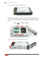
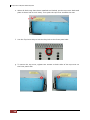
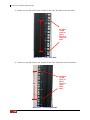
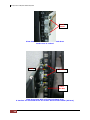
1
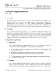
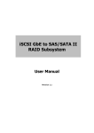
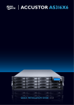
42 Bays SAS to SAS/SATA JBOD Subsystem User Manual Revision 1.0 42 Bays SAS to SAS/SATA JBOD Subsystem Table of Contents Preface ................................................................................................................................4 Before You Begin .............................................................................................................5 Safety Guidelines............................................................................................................................................................... 5 Controller Configurations .............................................................................................................................................. 5 Packaging, Shipment and Delivery ............................................................................................................................ 5 Unpacking the Shipping Carton ............................................................................................................................ 6 Chapter 1 1.1 Product Introduction .................................................................................7 Technical Specifications ....................................................................................................................................... 8 Chapter 2 2.1 Identifying Parts of the JBOD Subsystem ............................................9 Main Components ................................................................................................................................................. 9 2.1.1 2.1.1.1 LCD Display Panel LED .....................................................................................................................10 2.1.1.2 HDD Status LEDs ................................................................................................................................ 10 2.1.2 2.2 Front View ........................................................................................................................................................ 9 Rear View ........................................................................................................................................................ 11 JBOD Controller Module ................................................................................................................................... 12 2.2.1 2.3 JBOD Controller Panel ............................................................................................................................... 12 Power Supply Fan Module (PSFM) ............................................................................................................... 14 2.3.1 PSFM Panel ....................................................................................................................................................16 2.4 Turbo Fan (Fan 06-1) .......................................................................................................................................... 17 2.5 Expander Module ................................................................................................................................................. 18 2.5.1 2.6 Expander Module Panel ........................................................................................................................... 18 Disk Tray ..................................................................................................................................................................19 2.6.1 Disk Drive Installation................................................................................................................................ 20 Chapter 3 Getting Started with the Subsystem................................................... 27 3.1 Installing the Rails and Mounting into Rack ............................................................................................ 27 3.2 Preparing the JBOD and Connecting to RAID Subsystem.................................................................. 40 3.3 Preparing the JBOD and Connecting to SAS HBA in Host System ................................................ 40 3.4 Powering On ..........................................................................................................................................................40 3.5 Powering Off .......................................................................................................................................................... 42 Chapter 4 Maintenance ............................................................................................. 43 4.1 Upgrading the JBOD Controller Firmware................................................................................................. 43 4.2 Replacing Subsystem Components .............................................................................................................. 46 4.2.1 2 Replacing a Disk Drive .............................................................................................................................. 47 User Manual 42 Bays SAS to SAS/SATA JBOD Subsystem 4.2.2 Replacing the JBOD Controller Module ............................................................................................ 55 4.2.3 Replacing the Power Supply Fan Module......................................................................................... 57 4.2.4 Replacing the Turbo Fan (Fan 06-1) ................................................................................................... 59 4.2.5 Replacing the Expander Module .......................................................................................................... 61 4.2.6 Replacing the Front Panel ....................................................................................................................... 67 4.2.7 Replacing the Bottom Board ..................................................................................................................72 User Manual 3 42 Bays SAS to SAS/SATA JBOD Subsystem Preface About this manual This manual provides information regarding the hardware features and installation of the 42Bay JBOD subsystem. Information contained in the manual has been reviewed for accuracy, but not for product warranty because of the various environment/OS/settings. Information and specifications will be changed without further notice. This manual uses section numbering for every topic being discussed for easy and convenient way of finding information in accordance with the user’s needs. The following icons are being used for some details and information to be considered in going through with this manual: NOTES: These are notes that contain useful information and tips that the user must give attention to in going through with the subsystem operation. IMPORTANT! These are the important information that the user must remember. WARNING! These are the warnings that the user must follow to avoid unnecessary errors and bodily injury during hardware and software operation of the subsystem. CAUTION: These are the cautions that user must be aware of to prevent damage to the subsystem and/or its components. Copyright No part of this publication may be reproduced, stored in a retrieval system, or transmitted in any form or by any means, electronic, mechanical, photocopying, recording or otherwise, without the prior written consent. Trademarks All products and trade names used in this document are trademarks or registered trademarks of their respective owners. Changes The material in this document is for information only and is subject to change without notice. 4 User Manual 42 Bays SAS to SAS/SATA JBOD Subsystem Before You Begin Before going through with this manual, you should read and focus on the following safety guidelines. Notes about the subsystem’s controller configuration and the product packaging and delivery are also included here. Safety Guidelines To provide reasonable protection against any harm on the part of the user and to obtain maximum performance, user is advised to be aware of the following safety guidelines particularly in handling hardware components: Upon receiving of the product: Place the product in its proper location. Do not try to lift it by yourself alone. Two or more persons are needed to remove or lift the product to its packaging. To avoid unnecessary dropping out, make sure that somebody is around for immediate assistance. It should be handled with care to avoid dropping that may cause damage to the product. Always use the correct lifting procedures. Upon installing of the product: Ambient temperature is very important for the installation site. It must not exceed 30◦C. Due to seasonal climate changes; regulate the installation site temperature making it not to exceed the allowed ambient temperature. Before plugging-in any power cords, cables and connectors, make sure that the power switches are turned off. Disconnect first any power connection if the power supply module is being removed from the enclosure. Outlets must be accessible to the equipment. All external connections should be made using shielded cables and as much as possible should not be performed by bare hand. Using anti-static hand gloves is recommended. In installing each component, secure all the mounting screws and locks. Make sure that all screws are fully tightened. Follow correctly all the listed procedures in this manual for reliable performance. Controller Configurations This JBOD subsystem supports dual JBOD controller configurations. Packaging, Shipment and Delivery Before removing the subsystem from the shipping carton, you should visually inspect the physical condition of the shipping carton. Unpack and verify that the contents of the shipping carton are complete and in good condition. Exterior damage to the shipping carton may indicate that the contents of the carton are damaged. If any damage is found, do not remove the components; contact the dealer where you purchased the subsystem for further instructions. User Manual 5 42 Bays SAS to SAS/SATA JBOD Subsystem Unpacking the Shipping Carton The shipping carton contains the following: JBOD Subsystem Unit 42 Disk Trays Two (2) power cords Two (2) external SAS cables Four (4) serial external serial cables RJ11to-DB9 Key of Top Cover Key of Disk Tray User Manual NOTE: If any damage is found, contact the dealer or vendor for assistance. 6 User Manual 42 Bays SAS to SAS/SATA JBOD Subsystem Chapter 1 Product Introduction The 42 bays JBOD Subsystem The JBOD subsystem features 6Gb SAS host channels for increased system efficiency and performance. It is designed to be connected to the 42bay RAID Subsystem as expansion chassis, or directly to a host system’s SAS HBA. It features high capacity expansion, with 42 hot-swappable 6Gb/s SAS/SATA hard disk drive bays in a 19-inch 4U rackmount unit, scaling to a maximum storage capacity in the terabyte range. Features - 42 hot-swappable drive bays in a rackmount 4U chassis - Simultaneously support SAS2 or SATA3 disk - Dual SAS2 JBOD controller module - Each SAS2 JBOD controller module consist of three mini SAS (4X) port - Power Supply and cooling system contained in 1 module for efficient cooling - Two 1100W redundant hot swappable power supplies - Incorporates a cableless design for maximum signal integrity - Utilizes industry-standard SCSI Enclosure Services to monitor enclosure and disk environmental conditions Enclosure monitoring - S.E.S. support for standard enclosure management - System LED indications - Fan speed monitoring - Power supply monitoring - System voltage monitoring - System temperature monitoring - System alarm User Manual 7 42 Bays SAS to SAS/SATA JBOD Subsystem 1.1 Technical Specifications RAID Controller JBOD Controller option Redundant Host Interface Two 6Gb/s 4x mini SAS (SFF-8088) Disk Interface 6Gb/s SAS, SATA SAS Expander Four 6Gb/s 4x mini SAS (SFF-8088) - Direct Attached 42 Disks - Expansion Refer to RAID controller specification Monitor Port support Yes Enclosure Platform Rackmount Form Factor 4U # of Hot Swap Trays 42 Tray Lock Yes Disk Status Indicator Access / Fail LED Backplane SAS2 / SATA3 Single BP # of PS/Fan Modules 1100W x 2 w/PFC # of Fans 11 Power requirements AC 100V ~ 240V (+/-10%) Full Range 50Hz~60Hz Environmental Relative Humidity 10% ~ 85% Non-condensing Operating Temperature 10°C ~ 40°C (50°F ~ 104°F) Physical Dimension 810(L) x 482.6(W) x 176(H) mm Weight (Without Disk) 50 Kg Specification is subject to change without notice. 8 User Manual 42 Bays SAS to SAS/SATA JBOD Subsystem Chapter 2 Identifying Parts of the JBOD Subsystem 2.1 Main Components 2.1.1 Front View IMPORTANT: When powering off the JBOD subsystem, turn off first the Main Switch and allow at least 3 minutes (during which each disk slot starting from slot #1 until slot #42 will be powered down) for the subsystem to shutdown properly. Then turn off the switches of the 2 Power Supply Fan Modules. User Manual 9 42 Bays SAS to SAS/SATA JBOD Subsystem 2.1.1.1 LCD Display Panel LED Part Function Power LED Green indicates power is ON. 2.1.1.2 HDD Status LEDs The Front Panel shows the disk drives status. Activity LED Power On/Fail LED Indicator Color Description Activity LED Blue Blinking Indicates the disk drive is busy or being accessed. Green Indicates the disk drive in this slot is good. RED Indicates the disk drive in this slot is defective or failed. LED is off Indicates there is no disk drive in this slot. Power On/Fail LED 10 User Manual 42 Bays SAS to SAS/SATA JBOD Subsystem 2.1.2 Rear View Fan 06-1 JBOD Module 1 Power Supply 01-1 Expander 1-1 Expander 2-1 Power Supply 01-2 JBOD Module 2 Expander 2-2 Expander 1-2 NOTE: Each Power Supply Module has 1 Power Supply and 5 Fans. The JBOD subsystem is logically divided into two enclosures for hardware monitoring. The functions of the Expander Modules are as follows: Module: Function/Description: Expander Module 1-1 (for Controller 1) Monitors Enclosure 1 (Disk slots 1 to 21, Power Supply 01-1, Fans 01-1, 02-1, 03-1, 04-1, and 05-1, and Turbo Fan 06-1). Note: “-1” means enclosure 1. Expander Module 2-1 (for Controller 2) Same function as Expander 1-1 Expander Module 1-2 (for Controller 1) Monitors Enclosure 2 (Disk slots 22 to 42, Power Supply 01-2, Fans 01-2, 02-2, 03-2, 04-2, and 05-2. Note: “-2” means enclosure 2. Expander Module 2-2 (for Controller 2) Same function as Expander 1-2 User Manual 11 42 Bays SAS to SAS/SATA JBOD Subsystem 2.2 JBOD Controller Module The JBOD subsystem includes dual 6Gb SAS-to-6Gb SAS/SATA JBOD Controller Module. JBOD Controller Module 2.2.1 JBOD Controller Panel 12 User Manual 42 Bays SAS to SAS/SATA JBOD Subsystem Part Description SAS In Port Use to connect to SAS HBA or to RAID subsystem’s SAS Expansion Port. SAS Expansion Port Use to connect to the SAS In Port of another JBOD subsystem. RS-232 Port Use to upgrade the firmware of the JBOD controller. Connect the RJ11-to-DB9 serial cable to your system’s serial port. Indicator Color Description Link LED Green Indicates expander has connected or linked. Activity LED Blinking Blue Indicated the expander is busy and being accessed. User Manual 13 42 Bays SAS to SAS/SATA JBOD Subsystem 2.3 Power Supply Fan Module (PSFM) The 42bay JBOD subsystem contains two 1100W Power Supply Fan Modules. All PSFM are inserted at the rear of the chassis. Front Panel Rear Side NOTE: Each PSFM delivers Full-Range 100V ~ 240V (+/-10%) voltage AC electricity. Each PSFM consists of 1 power supply and 5 fans. Two Fans are located at the panel side, and three fans are located in rear side of the PSFM. 14 User Manual 42 Bays SAS to SAS/SATA JBOD Subsystem Power Supply 01-1 Fan 01-1 Fan02-1 Power Supply 01-2 Fan 01-2 Fan 02-2 Rear Side Front Panel NOTE: The first PSFM (01-1, on the left side of enclosure) has five fans: Fan 01-1 and Fan 02-1 on the front panel; and Fan 03-1, Fan 04-1 and Fan 05-1 on the rear side. The second PSFM (01-2, on the right side) has five fans also: Fan 01-2 and Fan 02-2 on the front panel; and Fan 03-2, Fan 04-2 and Fan 05-2 on the rear side. NOTE: “-1” means enclosure 1 and “-2” means enclosure 2. User Manual 15 42 Bays SAS to SAS/SATA JBOD Subsystem 2.3.1 PSFM Panel Part Description AC Power Input Socket Use to connect the power cord from power source. Power On/Off Switch Use to power on or power off the PSFM. Indicator Color Description Green Indicates the power supply module is good. Red Indicates the power supply module is faulty. Red Indicates one or more fans in the PSFM has failed. Power Status LED Fan Fail LED When the power cord connected from main power source is inserted to the AC Power Input Socket the Power Status LED becomes RED. When the switch of the PSFM is turned on, the LED still shows RED. After the main switch in front panel is turned on, the LED turns GREEN, which means it is functioning normally. The PSFM has a 5V standby DC voltage. When the power cord(s) is/are connected to the AC Power Input Socket, after 1 second, all 42 Activity LEDs will flash once. When the power cord(s) is/are disconnected from AC Power Input Socket, after 3 seconds, all 42 Activity LEDs will flash twice. 16 User Manual 42 Bays SAS to SAS/SATA JBOD Subsystem 2.4 Turbo Fan (Fan 06-1) The turbo fan provides additional airflow inside the enclosure. Turbo Fan LED Indicator Color Description Status LED Red Indicates the turbo fail is faulty. NOTE: The status of Turbo Fan (Fan 06-1) is monitored by Expander Module 1. User Manual 17 42 Bays SAS to SAS/SATA JBOD Subsystem 2.5 Expander Module The Expander Module contains the SAS expander. It can be used to upgrade the SAS expander firmware. It also contains the SES module (SCSI Enclosure Services). SES is the protocol used for enclosure environmental control. The SES module monitors the following enclosure conditions: temperature, power supply voltage, and fan speed. 2.5.1 Expander Module Panel Part Description RS-232 Port Use to upgrade the firmware of the expander module. Connect the serial cable RJ11-to-DB9 to your system’s serial port. Indicator Color Description Activity LED Blinking Green Indicates the expander module is busy or active. Fault LED Binking Red Indicates the expander module is faulty or has failed. 18 User Manual 42 Bays SAS to SAS/SATA JBOD Subsystem 2.6 Disk Tray The Disk Tray houses a 3.5 inch hard disk drive. It is designed for maximum airflow and incorporates a carrier locking mechanism to prevent unauthorized access to the HDD. Key for Disk Tray Lock User Manual 19 42 Bays SAS to SAS/SATA JBOD Subsystem 2.6.1 Disk Drive Installation This section describes the physical locations of the hard drives supported by the subsystem and give instructions on installing a hard drive. The subsystem supports hot-swapping allowing you to install or replace a hard drive while the subsystem is running. NOTE: When the JBOD subsystem is shipped, the disk trays are not placed in the disk slots. If all disk trays will be used to install all 42 disk drives, for quicker and easier installation of disk drives in the JBOD subsystem, it is recommended to install first each disk drive in a disk tray. After installing the disk drives, insert 14 disk trays into one row of 14 slots at a time and lock them one by one. Do the same for the next row until the last row. Disk Slots NOTE: When the subsystem is already in operational mode, it is not recommended to open the top cover for a long period of time; proper air flow within the enclosure might fail causing high disk drive temperature. 20 User Manual 42 Bays SAS to SAS/SATA JBOD Subsystem IMPORTANT: In dual controller mode, the installation of SATA disk drive in a disk tray is done differently. In single controller mode, the installation of SATA disk in a disk tray is the same with SAS disk. HDD Single Controller Dual Controller SATA No need dongle board Need dongle board SAS No need dongle board No need dongle board NOTE: In this model, it is recommended to use 6Gb hard drive disks. To install a SATA disk drive (Dual Controller Mode) in a disk tray: 1. Use the Key for Disk Tray Lock to unlock a disk tray. 2. Prepare the dongle board with metal bracket. User Manual 21 42 Bays SAS to SAS/SATA JBOD Subsystem 3. Connect the dongle board into the SATA disk drive. 4. Place the SATA disk drive into the disk tray. Turn the disk tray upside down. To secure the disk drive into the disk tray, tighten 4 screws on the holes of the disk tray. Note in the picture below where the screws should be placed in the disk tray holes. 4 screws #6-32 UNC L=5.0mm 5. Tighten 2 screws of the dongle board metal bracket. 22 User Manual 42 Bays SAS to SAS/SATA JBOD Subsystem To install a SAS disk drive (Single or Dual Controller Mode) or SATA disk drive (Single Controller Mode) in a disk tray: 1. Use the Key for Disk Tray Lock to unlock a disk tray. 2. Place the disk drive into the disk tray. 3. Turn the disk tray upside down. To secure the disk drive into the disk tray, tighten 4 screws on the holes of the disk tray. Note in the picture below where the screws should be placed in the disk tray holes. 4 screws #6-32 UNC L=5.0mm User Manual 23 42 Bays SAS to SAS/SATA JBOD Subsystem To install the disk trays into the disk slots: a. Loosen two screws on both sides of the top cover on the front panel side. b. Use the Top Cover Key to unlock the key lock on the front panel side. c. Hold the front part of the top cover and slide the top cover about half an inch towards the front side then pull upwards to remove it. 24 User Manual 42 Bays SAS to SAS/SATA JBOD Subsystem d. Insert each disk tray with disk drive one by one, 14 disk trays or one row first, and then lock each disk tray. Then do the same for the next 14 disk trays or row. To install the disk tray into the disk slot, insert it first in the slot. Then push down the latch part of disk tray as indicated in the picture below until it reached a full stop. Close the lever handle then use the Key for Disk Tray Lock and turn the disk tray lock into “locked” position. User Manual 25 42 Bays SAS to SAS/SATA JBOD Subsystem e. When all disk trays have been installed and locked, put the top cover back and place it about half an inch away. Then push the top cover towards the rear. f. Use the Top Cover Key to lock the key lock on the front panel side. g. To secure the top cover, tighten two screws on both sides of the top cover on the front panel side. 26 User Manual 42 Bays SAS to SAS/SATA JBOD Subsystem Chapter 3 Getting Started with the Subsystem This chapter contains information about the steps needed to start using the subsystem. If the subsystem will be installed in a rackmount cabinet, follow the steps in Section 3.1, otherwise, proceed with Section 3.2. 3.1 Installing the Rails and Mounting into Rack NOTE: At least two persons are needed to lift the subsystem. To reduce the weight of the subsystem, remove the 2 power supply modules from the rear of subsystem. If disk drives are already installed in the disk trays, remove also the disk trays. Refer to appropriate sections on how to remove the power supply modules and how to remove the disk trays/disk drives. NOTE: The subsystem must be installed near the Disk Array or host system where it will be connected. A Phillips screwdriver is needed in installation. WARNING! It is prohibited to put other enclosures/subsystems on top of the 42-bay subsystem because the total weight will not be supported by the rails. Steps: 1. Open the rail box. 2. Remove the 2 rail assemblies and the screws/accessories from the box. Check its contents. User Manual 27 42 Bays SAS to SAS/SATA JBOD Subsystem 3. Insert two (2) M5 nuts on the 2 holes of the front left side of the rack post. 4U Position of M5 nuts on the 2 holes of left rack post Rack Post – Front Left Side 4. Insert two (2) M5 nuts on the 2 holes of the front right side of the rack post. 4U Rack Post – Front Right Side 28 User Manual Position of M5 nuts on the 2 holes of right rack post 42 Bays SAS to SAS/SATA JBOD Subsystem 5. Prepare the 2 rail assemblies. Front Side of Rail Assembly Rear Side of Rail Assembly 6. Hold one rail assembly and install in the front left side of rack. To install, align and insert the 2 latches of the rail into the 2 holes on the rack post. Use the Lock Lever to lock the rail assembly in the left rack post. Lock Lever Lower M5 nut View from Front Side of Front Left Rack Post Lock Lever is Not Locked User Manual 29 42 Bays SAS to SAS/SATA JBOD Subsystem Lock Lever View from Front Side of Front Left Rack Post Lock Lever is Locked 6th Lock 5th 2 Latches 4th 3rd 2nd 1st Lower M5 Nut View from Rear Side of Front Left Rack Post 2 Latches are inserted in the 4th and 6th holes from bottom (M5 nut) 30 User Manual 42 Bays SAS to SAS/SATA JBOD Subsystem 7. Install the other end of rail assembly to the left rear side. Align and insert the 2 latches on the 2 holes on the rear rack post, and then push the rail a little towards the rear side and lock the lock lever on the rack post. Lock Lever Latches View from Rear Side of Rear Left Rack Post Lock Lever Latches View from Rear Side of Rear Left Rack Post Lock Lever View from Rear Side of Rear Left Rack Post User Manual 31 42 Bays SAS to SAS/SATA JBOD Subsystem 8. Repeat step 6 to install the other rail assembly into the right front side. Lock Lever Lower M5 nut View from Front Side of Front Right Rack Post Lock Lever is Not Locked Lock Lever Lower M5 nut View from Front Side of Front Right Rack Post Lock Lever is Locked 32 User Manual 42 Bays SAS to SAS/SATA JBOD Subsystem 6th 2 Latches Lock 5th 4th 3rd 2nd Lower M5 nut 1st View from Rear Side of Front Right Rack Post 2 Latches are inserted in the 4th and 6th holes from bottom (M5 nut) 9. Repeat step 7 to install the other end of rail assembly to the rack post of rear right side. Lock Lever Latches View from Rear Side of Rear Right Rack Post User Manual 33 42 Bays SAS to SAS/SATA JBOD Subsystem Latches Lock Lever View from Rear Side of Rear Right Rack Post Latches Lock View from Rear Side of Rear Right Rack Post 34 User Manual 42 Bays SAS to SAS/SATA JBOD Subsystem 10. Install the inner rail member on the side of the enclosure. Align the holes on the inner rail then slide a little towards the front side until locked. Inner Rail Member Inner Rail Member Placed on the Side of Enclosure Inner Rail Member Pushed Towards the Front Side and Locked User Manual 35 42 Bays SAS to SAS/SATA JBOD Subsystem 11. Repeat step 10. Insert the other inner rail member on the other side of enclosure. 12. Pull the 2 middle rail members out from the rail assembly. Front Left Side Rear Left Side Middle Rail Member of Rail Assembly on Left Side of Rack Right Front Side Front Side View from Rear Side 36 User Manual Left Front Side 42 Bays SAS to SAS/SATA JBOD Subsystem 13. With at least 2 persons carrying the enclosure, insert the 2 inner rails (attached to the sides of the enclosure) into the middle rails. Slide the enclosure until it stops or about half way through. NOTE: Be careful when inserting the 2 inner rails into the middle rails. The 2 inner rails must be parallel with the 2 middle rails so that 2 inner rails will insert and slide easily. Inner Rail Middle Rail Inner Rail Aligned with Middle Rail View from Rear Side User Manual 37 42 Bays SAS to SAS/SATA JBOD Subsystem 14. Press outwards the blue locks on both sides of the inner rail members at the same time. Then push the enclosure inwards until it goes inside the rack. Blue Lock of Inner Rail View from Right Side of Enclosure Blue Lock of Inner Rail is Pushed a Little Outwards and Enclosure is Pushed Inwards View from Rear Side of Rack Cabinet Enclosure is Pushed Inwards 38 User Manual 42 Bays SAS to SAS/SATA JBOD Subsystem 15. Insert the 2 power supply modules. 16. Open the top cover and re-insert the disk drives / disk trays, if disk drives/disk trays were previously removed. Then close the top cover. 17. Use four (4) M5 screws to lock the enclosure into the rack post. Front Left Side Front Right Side User Manual 39 42 Bays SAS to SAS/SATA JBOD Subsystem 3.2 Preparing the JBOD and Connecting to RAID Subsystem 1. Install the disk drives, if not yet installed. Refer to Section 2.6.1 Disk Drive Installation for detailed information. 2. Connect one end of SAS cable to the SAS In Port of the JBOD subsystem enclosure and the other end to the SAS Expansion Port of the RAID subsystem enclosure. 3.3 Preparing the JBOD and Connecting to SAS HBA in Host System 1. Install the disk drives, if not yet installed. Refer to Section 2.6.1 Disk Drive Installation for detailed information. 2. Connect one end of SAS cable to the SAS In Port of the JBOD subsystem enclosure and the other end to the SAS HBA on the Host system. 3.4 Powering On 1. Plug in all the power cords into the AC Power Input Socket located at the PSFM. NOTE: The subsystem is equipped with redundant, full range power supplies with PFC (power factor correction). The system will automatically select voltage. NOTE: The PSFM has a 5V standby DC voltage. When the power cord(s) is/are connected to the AC Power Input Socket, after 1 second, all 42 Activity LEDs will flash once. When the power cord(s) is/are disconnected from AC Power Input Socket, after 3 seconds, all 42 Activity LEDs will flash twice. 40 User Manual 42 Bays SAS to SAS/SATA JBOD Subsystem 2. Turn on each Power On/Off Switch of the PSFM. NOTE: When the power cord connected from main power source is inserted to the AC Power Input Socket, the Power Status LED becomes RED. When the switch of the PSFM is turned on, the LED still shows RED. After the main switch in front panel is turned on, the LED turns GREEN, which means it is functioning normally. Power Supply 01-1 Power Supply 01-2 3. To power on the subsystem, turn on the main switch (open first the switch cover) in the right corner side of front panel. Main Switch 4. Allow the machine a few moments to initialize before using it. NOTE: The system will initialize after turning on the Main Switch. Each disk slot will be checked during subsystem initialization. 5. Configure RAID using either the RAID subsystem (if JBOD subsystem is connected to RAID subsystem), or the software utility provide with the SAS HBA (if JBOD subsystem is connected to SAS HBA in the host system). User Manual 41 42 Bays SAS to SAS/SATA JBOD Subsystem 3.5 Powering Off IMPORTANT: When powering off the JBOD subsystem, turn off first the Main Switch and allow at least 3 minutes for the subsystem to shutdown properly. During this time, each disk slot starting from slot #1 until slot #42 will be powered down. When subsystem has totally powered down, turn off the switches of the 2 Power Supply Fan Modules at the rear. Sequence of disk slot power down (from slot 1 to slot 42) 42 User Manual 42 Bays SAS to SAS/SATA JBOD Subsystem Chapter 4 Maintenance 4.1 Upgrading the JBOD Controller Firmware NOTE: The JBOD firmware upgrade procedure must be done three times. First is on the JBOD Controller, next is on the Expander Module 1-1, then last on the Expander Module 1-2. NOTE: There must be no I/O in the disk drives in the JBOD subsystem (RAID volumes should not be accessed) during firmware upgrade. JBOD Module 1 JBOD Module 2 1 2 3 Expander 1-1 Expander 1-2 A VT100 compatible terminal or a PC operating in an equivalent terminal emulation mode is needed to upgrade the firmware. NOTE: It is important to stop I/O access to JBOD subsystem during firmware upgrade. NOTE: Upgrading the firmware must be done from Master JBOD Controller if the JBOD Subsystem has redundant JBOD Controllers. User Manual 43 42 Bays SAS to SAS/SATA JBOD Subsystem 1. Please use the RS232 cable (RJ11 to DB9) to JBOD Controller #1 and to connect JBOD RS232 Port and PC COM1 Port (or change to other COM Port as necessary). 2. Open Windows HyperTerminal Program. Connect using COM1 (COM Port used in Step1), Baud Rate: 115200, n, 8, 1, Flow Control: None. 3. Press the Enter key and the password prompt will be displayed. 4. Key in the password (Default password: 00000000) to login to CLI. 5. At CLI prompt, input the command to update firmware. a. CLI> mo Operation Mode: Redundant, I2C Master, CLI DUAL Operation Mode: Redundant, I2C Backup NOTE: If Operation Mode is “Redundant, I2C Master, CLI Dual”, it means you are connected to Master Expander and you can continue with next steps. If Operation Mode is “Redundant, I2C Backup”, it means you are connected to Backup Expander. Remove RS232 serial cable and insert to other JBOD RS232 Port. b. CLI> mo fdl both c. CLI> mo Operation Mode: Redundant, I2C Master, fdl both d. CLI> NOTE: “fdl code” is the command to update flash firmware code (.fw file). “fdl mfgb” is the command to update CFG data code (.rom file) Make sure you have both files before updating. e. CLI> fdl mfgb Please Use XModem Protocol for File Transmission. Use Q or q to quit Download before starting XModem. Offset = 0x0 f. Select Function menu to transfer CFG data .rom file: “Function” Î “Transfer” Î “Send File” Î “Browse” Î “Open” and select the .rom file (for example: 8016-mfgdat6-20110131.rom) firmware folder location. Select “Xmodem” Protocol to send firmware file (Only need about 60 seconds to finish sending firmware file. If not, please repeat steps B and D again). Note. If won’t to transfer CFG data .rom file, Press Q or q to quit Download before starting data transfer. 44 User Manual 42 Bays SAS to SAS/SATA JBOD Subsystem g. CLI>fdl code Please Use XModem Protocol for File Transmission. Use Q or q to quit Download before starting XModem. Offset = 0x0 h. Select Functon menu to transfer firmware file: “Function” Î “Transfer” Î “Send File” Î “Browse” Î “Open” and select the .fw file (for example: 8016-07.01.09.96-20110211.fw) from firmware folder location. Select “Xmodem” Protocol to send firmware file (Only need about 60 seconds to finish sending firmware file. If not, please repeat steps D and E again). Note. If won’t to transfer firmware data .fw file, Press Q or q to quit Download before starting data transfer. i. Use “reset” command to Restart JBOD or power cycle j. Re-login to JBOD CLI. k. Use “sys” command to verify JBOD firmware version. CLI>sys l. If needed, the “reset” command can also be used to restart the JBOD controller. (Normally used in single JBOD Controller mode, If already to connect to Controller ) CLI>reset User Manual 45 42 Bays SAS to SAS/SATA JBOD Subsystem 4.2 Replacing Subsystem Components CAUTION: When replacing the components of the subsystem, make sure to handle the parts carefully. When handling ESD sensitive parts such as boards or PCBA, it is recommended to use anti-static hand gloves or wrist strap. Make sure somebody is around to give help when servicing the subsystem. Take note of the following when replacing the components of the subsystem. Hot Swappable (Subsystem is online) Need to Power Off (Subsystem should be offline) Disk Drive Trays Front Panel Power Supply Bottom Board JBOD Controller (dual controller mode) JBOD Controller (single controller mode) SAS Expander (dual controller mode) SAS Expander (single controller mode) Turbo Fan (Fan 06-1) IMPORTANT: (1.) When the subsystem is online and a Power Supply fails, and the replacement Power Supply module is not yet available, don’t remove or disconnect the failed Power Supply module. This is to maintain proper airflow within the enclosure, since the fans will still be working. (2.) When the subsystem is online and a Controller module or SAS Expander module fails and the replacement is not yet available, in order to maintain proper airflow within the enclosure, the failed module can be disconnected just about an inch but not entirely removed from the slot. This is to maintain proper airflow within the enclosure. (3.) When replacing a failed component online, it is not recommended to remove the failed component for a long period of time; proper air flow within the enclosure might fail causing high controller / disk drive temperature. 46 User Manual 42 Bays SAS to SAS/SATA JBOD Subsystem 4.2.1 Replacing a Disk Drive NOTE: When the subsystem is already in operational mode, it is not recommended to open the top cover for a long period of time; proper air flow within the enclosure might fail causing high disk drive temperature. To replace a disk drive: 1. Loosen two screws on both sides of the top cover on the front panel side. 2. Use the Top Cover Key to unlock the key lock on the front panel side. 3. Hold the front part of the top cover and slide the top cover about half an inch towards the front side then pull upwards to remove it. User Manual 47 42 Bays SAS to SAS/SATA JBOD Subsystem 4. To remove the disk tray containing the disk drive to be replaced, unlock the disk tray lock using the key for disk tray lock. The lever handle will automatically open. If the lever handle does not automatically open, pull upwards the tip of the lever handle (part where the tray lock is located). Then pull upwards the lever handle of the disk tray. 5. Remove the 4 screws on the bottom part of the disk tray. Note that replacing SATA disk drive in dual controller mode is done differently. IMPORTANT: In dual controller mode, the replacement process of SATA disk drive in a disk tray is done differently. In single controller mode, the replacement process of SATA disk in a disk tray is the same with SAS disk. 48 HDD Single Controller Dual Controller SATA No need dongle board Need dongle board SAS No need dongle board No need dongle board User Manual 42 Bays SAS to SAS/SATA JBOD Subsystem For SATA Disk Drive (Dual Controller Mode): a. Remove the 4 screws as indicated in the picture. b. Remove the 2 screws on the dongle board metal bracket. c. Disconnect the dongle board metal bracket. d. Connect the dongle board metal bracket into the new SATA disk drive. User Manual 49 42 Bays SAS to SAS/SATA JBOD Subsystem e. Place the disk drive with dongle board into the disk tray. To secure the disk drive in the disk tray, tighten the 4 screws that were removed before. f. 50 Tighten the 2 screws of the dongle board metal bracket. User Manual 42 Bays SAS to SAS/SATA JBOD Subsystem For SAS Disk Drive (Single or Dual Controller Mode) or SATA Disk Drive (Single Controller Mode): a. Remove the 4 screws as indicated in the picture. b. Remove the disk drive from the disk tray and place the new disk drive. c. To secure the disk drive in the disk tray, tighten the 4 screws that were removed before. User Manual 51 42 Bays SAS to SAS/SATA JBOD Subsystem 6. Insert the disk tray into the disk slot. 7. Then push down the latch part of disk tray as indicated in the picture below until it reached a full stop. 52 User Manual 42 Bays SAS to SAS/SATA JBOD Subsystem 8. Close the lever handle then use the Key for Disk Tray Lock and turn the disk tray lock into “locked” position. 9. When all disks that need to be replaced have been replaced, put the top cover back and place it about half an inch away. Then push the top cover towards the rear. 10. Use the Top Cover Key to lock the key lock on the front panel side. User Manual 53 42 Bays SAS to SAS/SATA JBOD Subsystem 11. To secure the top cover, tighten two screws on both sides of the top cover on the front panel side. 54 User Manual 42 Bays SAS to SAS/SATA JBOD Subsystem 4.2.2 Replacing the JBOD Controller Module To replace a JBOD Controller Module: 1. Loosen the 2 thumbscrews of the JBOD controller module. 2. Pull the handle outwards. The lock will disengage and the controller module will move out from the slot. Use the Controller handle to pull out the defective Controller. 3. Pull out the controller module. User Manual 55 42 Bays SAS to SAS/SATA JBOD Subsystem 4. Insert the controller module into the slot. 5. With the handle in open position, push the controller module handle until the lock is engaged. 6. Tighten the 2 thumbscrews on the controller module handle. 56 User Manual 42 Bays SAS to SAS/SATA JBOD Subsystem 4.2.3 Replacing the Power Supply Fan Module Before replacing a PSFM, turn off the PSFM switch and disconnect the power cable from the AC Power Input Socket. To replace a Power Supply Fan Module: 1. Loosen the thumbscrews of the Power Supply Fan Module. 2. Pull the handle of the Power Supply Fan Module. The Power Supply Fan Module will move out from the slot. 3. Prepare the new Power Supply Fan Module. User Manual 57 42 Bays SAS to SAS/SATA JBOD Subsystem 4. Insert the replacement Power Supply Fan Module and push inwards. With the handle in open position, close the handle until the lock is engaged. 5. Tighten the 2 thumbscrews of the PSFM. 58 User Manual 42 Bays SAS to SAS/SATA JBOD Subsystem 4.2.4 Replacing the Turbo Fan (Fan 06-1) To replace the Turbo Fan Module: 1. Loosen the 2 screws of the Turbo Fan Module. 2. Pull the handle to remove the Turbo Fan Module from the slot. 3. Insert the replacement Turbo Fan Module. NOTE: If only the fan board will be replaced, disconnect first the fan cables, loosen the screws on the fan board, and replace the fan board. User Manual 59 42 Bays SAS to SAS/SATA JBOD Subsystem 4. Push the Turbo Fan Module until it is fully inserted. 5. Tighten the 2 screws of the Turbo Fan Module. 60 User Manual 42 Bays SAS to SAS/SATA JBOD Subsystem 4.2.5 Replacing the Expander Module CAUTION: Be careful when inserting the Expander Module. Carefully insert the module and make sure that the connector pins are not bent when the module is inserted. To replace Expander Module: 1. Loosen the thumbscrew of the Expander Module. 2. Pull the thumbscrew just a little. User Manual 61 42 Bays SAS to SAS/SATA JBOD Subsystem 3. Hold the rear part of the thumbscrew handle with your thumb and your forefinger (index finger) on the other screw. Carefully move your thumb outwards to disengage the lock. 4. The lock will totally disengage and the expander module will move out from the slot. 62 User Manual 42 Bays SAS to SAS/SATA JBOD Subsystem 5. Carefully pull out the handle to remove the expander module. 6. Remove the 2 screws from the heat sink. Remove the 6 screws from the Expander PCBA. 7. Place the new Expander PCBA and tighten the screws that were removed before. User Manual 63 42 Bays SAS to SAS/SATA JBOD Subsystem 8. Insert the Expander module in its slot. 9. Make sure the lever lock is in open position. Carefully close the handle. 64 User Manual 42 Bays SAS to SAS/SATA JBOD Subsystem 10. Carefully push the thumbscrew handle until the lock is engaged. User Manual 65 42 Bays SAS to SAS/SATA JBOD Subsystem 11. Make sure the thumbscrew handle is totally connected to the expander module panel. Tighten the thumbscrew. 66 User Manual 42 Bays SAS to SAS/SATA JBOD Subsystem 4.2.6 Replacing the Front Panel To replace the Front Panel: 1. Loosen two screws on both sides of the top cover on the front panel side. 2. Use the Top Cover Key to unlock the key lock on the front panel side. 3. Hold the front part of the top cover and slide the top cover about half an inch towards the front side then pull upwards to remove it. User Manual 67 42 Bays SAS to SAS/SATA JBOD Subsystem 4. Loosen the 2 screws on both sides of the front panel. 5. Hold the front panel on both sides and carefully detach the front panel from the enclosure. Note that the main switch cable is connected to the front panel. Disconnect the cable. 68 User Manual 42 Bays SAS to SAS/SATA JBOD Subsystem 6. Replace the front panel. 7. Reconnect the cable to the front panel. User Manual 69 42 Bays SAS to SAS/SATA JBOD Subsystem 8. Hold the front panel and carefully attach to the enclosure. Note that there are 4 contact points which the front panel must connect to. 9. Tighten the 2 screws on the front panel side. 70 User Manual 42 Bays SAS to SAS/SATA JBOD Subsystem 10. Put the top cover back and place it about half an inch away. Then push the top cover towards the rear. 11. Use the Top Cover Key to lock the key lock on the front panel side. 12. To secure the top cover, tighten two screws on both sides of the top cover on the front panel side. User Manual 71 42 Bays SAS to SAS/SATA JBOD Subsystem 4.2.7 Replacing the Bottom Board The subsystem has 2 bottom boards. One or both bottom boards can be replaced, if necessary. To replace a Bottom Board: 1. Loosen two screws on both sides of the top cover on the front panel side. 2. Use the Top Cover Key to unlock the key lock on the front panel side. 3. Hold the front part of the top cover and slide the top cover about half an inch towards the front side then pull upwards to remove it. 72 User Manual 42 Bays SAS to SAS/SATA JBOD Subsystem 4. Loosen the 2 screws on both sides of the front panel. 5. Hold the front panel on both sides and carefully detach the front panel from the enclosure. Note that the main switch cable is connected to the front panel. Disconnect the cable. User Manual 73 42 Bays SAS to SAS/SATA JBOD Subsystem 6. Place the front panel in a safe place. 7. If the right bottom board will be replaced, unlock and remove disk trays 1 to 21 and hung the trays in the slots. If the left bottom board will be replaced, unlock and remove disk trays 22 to 42 and hung the trays in the slots. 74 User Manual 42 Bays SAS to SAS/SATA JBOD Subsystem 8. Loosen 2 screws on the bottom part of the subsystem, on the subsystem side of the bottom board to be removed. (To have access to the 2 screws, the subsystem need to be moved a few inches forward.) 9. Loosen the 2 thumbscrews of the bottom board then pull the 2 thumbscrews. The bottom board will detach from the enclosure. Pull the bottom board outwards. 10. Replace the bottom board. If necessary, remove the screws from the bottom board and place the new bottom board then tighten back the screws. User Manual 75 42 Bays SAS to SAS/SATA JBOD Subsystem 11. Before reinserting the bottom board, the expander module(s) need to be removed. This is a precautionary step to prevent the connector pins of the expander module(s) from possibly being bent when the bottom board is inserted. Refer to Section on Replacing the Expander Module for steps on how to remove or reinsert the expander module. Controller Mode: Bottom Board that was/were Replaced: Expander Module(s) to be Removed: Single Controller Left 1-2 Single Controller Right 1-1 Single Controller Left and Right 1-1 and 1-2 Dual Controller Left 1-2 and 2-2 Dual Controller Right 1-1 and 2-1 Dual Controller Left and Right 1-1, 2-1, 1-2 and 2-2 Left Bottom Board Expander 1-1 Expander 2-1 76 User Manual Right Bottom Board Expander 2-2 Expander 1-2 42 Bays SAS to SAS/SATA JBOD Subsystem 12. Insert the bottom board into the bottom board slot. Slide the bottom board inwards. Make sure the 2 thumbscrews are in open position. Push the 2 thumbscrews until the bottom board is engaged in the enclosure. 13. Tighten the 2 thumbscrews of the bottom board. 14. Tighten the 2 screws on the bottom part of the subsystem, on the subsystem side of the bottom board that was replaced. 15. Reinsert the Expander Module(s) that was/were removed in Step 11. 16. Insert all the disk trays that were hung and lock them. 17. Reconnect the cable to the front panel. User Manual 77 42 Bays SAS to SAS/SATA JBOD Subsystem 18. Hold the front panel and carefully attach to the enclosure. Note that there are 4 contact points which the front panel must connect to. 19. Tighten the 2 screws on the front panel side. 78 User Manual 42 Bays SAS to SAS/SATA JBOD Subsystem 20. Put the top cover back and place it about half an inch away. Then push the top cover towards the rear. 21. Use the Top Cover Key to lock the key lock on the front panel side. 22. To secure the top cover, tighten two screws on both sides of the top cover on the front panel side. User Manual 79