1
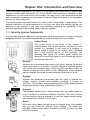
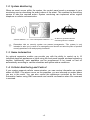
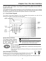
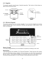
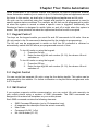
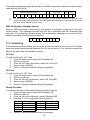
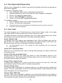
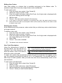
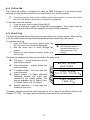
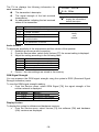
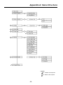
Version 0.01 (preliminary) Release Date: 24.9.02 Table of Contents Chapter One: Introduction and Overview ............................................................................................ 3 1.1: Security System Components ................................................................................................ 3 1.2: System Monitoring ................................................................................................................. 4 1.3: Home Automation .................................................................................................................. 4 1.4: Cellular Monitoring and Control.............................................................................................. 4 Chapter Two: The User Interface ........................................................................................................ 5 2.1: Front Panel Keypad ............................................................................................................... 5 2.2: Keyfobs .................................................................................................................................. 6 2.3: Wireless Keypad .................................................................................................................... 6 Chapter Three: Arming and Disarming ................................................................................................ 8 3.1: Arming the System................................................................................................................. 8 3.2: Disarming the System ............................................................................................................ 9 3.3: Arm Status Indication ............................................................................................................. 9 3.4: Arming Tones......................................................................................................................... 9 3.5: Remote Arming/Disarming via SMS..................................................................................... 10 Chapter Four: Panic Alarms .............................................................................................................. 11 4.1: Front Panel Panic Alarm ...................................................................................................... 11 4.2: Keyfob Panic Alarm.............................................................................................................. 11 4.3: Wireless Keypad Panic Alarm.............................................................................................. 11 Chapter Five: Home Automation ....................................................................................................... 12 5.1: Keypad Control .................................................................................................................... 12 5.2: Keyfob Control ..................................................................................................................... 12 5.3: SMS Control......................................................................................................................... 12 5.4: Scheduling ........................................................................................................................... 13 Chapter Six: Advanced System Operation ........................................................................................ 14 6.1: Stop Communications .......................................................................................................... 14 6.2: Zone Bypassing/Unbypassing.............................................................................................. 15 6.3: User Codes .......................................................................................................................... 15 6.4: Follow Me............................................................................................................................. 17 6.5: Event Log ............................................................................................................................. 17 6.6: Service Menu ....................................................................................................................... 18 Appendix A: Menu Structure.............................................................................................................. 20 Appendix B: Glossary ........................................................................................................................ 21 -2- Chapter One: Introduction and Overview This user manual explains all you need to know about your infiniti security system and provides step-by-step instructions for all the infiniti’s user functions. In addition to the explanation you will receive from your installer, we urge you to read this manual so that you can take full advantage of your system’s features. Keep this manual in an accessible location for future reference. The infiniti system has many features in order to suit a wide range of applications. This manual outlines all of these features but it is likely that there are options that are not relevant to your system. If you have any questions regarding the availability of the features described in the manual, please ask your installer. 1.1: Security System Components Your security system is made up of a control panel, various sensors and a number of optional peripheral devices. This section explains the role of each component in your system. Control Panel The control panel is the brain of the system. It communicates with all the devices connected to the system. For example, in the event of a burglary, a sensor sends a signal to the control panel indicating that it has sensed motion on the premises. On receiving this signal, the control panel makes the decision to report the alarm to your monitoring service and activate the siren. Sensors Sensors are the devices that protect your home, alerting the control panel when there is a breach in security. Magnetic contacts protect your doors and windows while motion sensors are able detect an intruder moving across its field of view. Additionally, smoke sensors can be installed to provide an early warning in the event of a fire. Keyfobs Keyfobs are hand-held transmitters that are used to operate the system. Various keyfobs are available providing a number of functions. For example, arming/disarming the system, sending panic alarms and various home automation functions. Keypads The keypads enable you to communicate with the control panel in order to perform a number of different functions. The main function you can perform using a keypad is to arm the system when leaving your home and to disarm on your return. Sirens While the control panel includes a built-in internal siren, it is possible that you also have an external siren installed. The sirens are sounded during certain alarm conditions serving to warn you and ward off intruders. -3- 1.2: System Monitoring When an event occurs within the system, the control panel sends a message to your monitoring service describing the exact nature of the event. This enables the monitoring service to take the required action. System monitoring can implement either regular telephone or cellular communication. An alarm is generated and the A sensor detects. The control panel is alerted. monitoring service is notified. , Remember that no security system can prevent emergencies. This system is only intended to alert you in case of an emergency and should not take the place of prudent security practices or life and property insurance. 1.3: Home Automation An optional expansion module can provide you with the ability to control up to 16 individual electrical appliances or lights using the front panel keypad, wireless keypads or keyfobs. Additionally, each appliance can be programmed to be turned on and off automatically according to various schedules and system status conditions. 1.4: Cellular Monitoring and Control If your system supports cellular communication, you can receive information on system status via SMS. If an alarm occurs on the premises, you are informed no matter where you are in the world. You can also control the appliances controlled by the Home Automation feature using SMS commands and receive confirmation when the command is received. -4- Chapter Two: The User Interface There are several methods you can use to operate the system. Apart from the keypad on the front panel, your system may include a number of peripheral devices such as keypads and keyfobs. This chapter provides a brief introduction to each of the devices you can use to operate the system. It is important that you familiarize yourself with these devices before reading the following chapters that shall describe system operation in further detail. 2.1: Front Panel Keypad The infiniti’s front panel keypad is the user interface that provides you with all the functions you need to control your security system. LCD Display System Status LEDs Arming Keys Menu Navigation Keys Alphanumeric Keypad System Status Indicators The System Status indicators provide essential information on the status of the system such as arm, disarm, alarm and power failure conditions. On during arm. Off during disarm. Flashes after alarm. On when power is connected. Off when power is disconnected. Flashes if there is a problem with mains power or the backup battery. Service Call Button The Service Call button enables you to contact the monitoring service and talk to an operator. Press and hold down the Service Call key for a few seconds to initiate a service call. Home Automation On/Off Keys Pressing one of the Home Automation keys followed by the unit number (01-16) enables you to control lights and appliances in your home. ON OFF Pressing both Home Automation keys simultaneously generates an SOS panic alarm. -5- 2.2: Keyfobs The system supports several types of keyfob transmitter. The function of the buttons on each keyfob are shown below. Disarm Full Arm Medical Emergency Part Arm or Home Automation Perimeter Arm or Home Automation EL-2614 EL2611 2.3: Wireless Keypad The system supports up to four wireless keypads. You can use the keypad as an arming station, perform basic home automation functions and generate a panic alarm in the event of emergency. Battery Status LEDs Numeric Keypad Arming Keys Cancel Numeric Keypad The numeric keypad allows you to arm/disarm the system by entering a user code. Arming Keys Three arming keys are available: Full, Part and Perimeter. These keys arm the system using one of the three arming methods. One-key Arming is an option that is programmed by your installer. If this option is disabled, you must also enter a user code when arming. Simultaneously pressing the Full and Perimeter buttons generates a panic alarm. -6- Home Automation On/Off Keys Pressing one of the Home Automation keys followed by the unit number (01-16) enables you to control lights and appliances in your home. Cancel The Cancel key clears the keypad in the event that you pressed a key by mistake. For example, when entering your code you enter a wrong digit, the system waits for you to enter all four digits before it decides that the code is incorrect. Pressing the Cancel key causes the keypad to ignore what was previously entered enabling you to start again. Battery Status LEDs Every time a key is pressed, one of the Battery Status LEDs is lit. When the battery needs to be replaced, the red Low Battery LED is lit. -7- Chapter Three: Arming and Disarming Arming can be defined as activating the system. When the system is armed, it monitors the zones that are protected by the sensors. If a sensor detects an intrusion, the system generates an alarm. Certain sensors, such as smoke sensors, are always active regardless of system status. 3.1: Arming the System Three arming modes are available: Full, Part and Perimeter. These modes enable you to arm your system using different methods. Full Arming Full arming activates the entire system. This arming method is used when you intend to leave your home, leaving the premises empty. Part Arming This arming method enables you to arm a section of your home while remaining on a different part of the premises. Perimeter Arming Perimeter arming enables you to activate the perimeter zones (the windows and doors of your home) enabling you to move freely within the protected area. Before arming the system, check that all doors and windows are secured so that the system is ready for arming. To arm the system using the keypad: • Press one of the three arming keys; the exit delay begins to count down. At the end of the exit delay, the system is armed. , If the One-key Arming option is disabled in programming, you must enter your user code when arming the system. To arm the system using a keyfob: • Press the relevant button on your keyfob (see Figure 2.3); the exit delay begins to count down. At the end of the exit delay, the system is armed. Forced Arming Forced arming enables you to arm when the system is not ready. For example, if a door protected by a magnetic contact is open, you may arm the system on condition that the door will be closed by the end of the Exit delay. If the door is still open after the exit delay expires, an alarm is generated. , Forced arming is available only if the option is enabled in programming. Forced arming may be enabled for specific zones or for the entire system. -8- 3.2: Disarming the System When you enter the premises, the entry delay begins to count down. You must disarm the system within the entry delay time to prevent the system from triggering an alarm. To disarm the system using the keypad: • Enter your user code. To disarm the system using a keyfob: • Press the disarm button – see 2.3: Keyfobs.. 3.3: Arm Status Indication The system’s arm status is displayed on the front panel only. The following table explains the various arm status descriptions that appear on the LCD display. This… DISARMED FULL ARMED PART ARMED PERIMETER ARMED FULL ARMING PART ARMING PERIMETER ARMING , DISARMED 11:22:02 Means… The system is disarmed. The system has been armed using the displayed arming method. The system is in the process of arming (displayed during exit delay). The system may be programmed to display arm status at all times or only for the first two minutes after you arm or disarm the system. 3.4: Arming Tones Arming tones are the chimes that the system FULL ARMING sounds during the entry/exit delay and when the 7 TO EXIT system arms or disarms. The system includes various options that determine the pattern of these tones. Arming tones may be sounded by either the external siren or the control panel’s built-in internal siren. -9- 3.5: Remote Arming/Disarming via SMS You can arm and disarm the system remotely by sending the SMS commands from a cellular phone to the cellular communications module. Each SMS command contains the following elements: • • • • SMS Command Descriptor (up to 43 characters of free text) # (separates the descriptor from the actual command) User Code Command (120=Disarm, 121=Full Arm, 122=Part Arm, 123=Perimeter Arm) The following example shows the format of an SMS command for disarming the system: User Code SMS Command Descriptor D i s a r m # 1 -10- 2 3 Command 4 1 2 0 Chapter Four: Panic Alarms A panic alarm enables you to send a message to the monitoring service in the event of emergency. There are several methods you can use to generate a panic alarm. 4.1: Front Panel Panic Alarm You can generate a panic alarm from the front panel keypad by pressing the Home Automation On and Off keys simultaneously. 4.2: Keyfob Panic Alarm Using the four-button keyfob, EL-2614, you can activate an panic alarm by pressing the lower two buttons simultaneously. Medical Emergency The EL-2611 is designed to send a message to your monitoring service in the event of a medical emergency. The transmitter is water-resistant and can be worn around the neck as a pendant. 4.3: Wireless Keypad Panic Alarm You can generate a panic alarm from the wireless keypad by pressing the Full Arm and Perimeter Arm keys simultaneously. -11- Chapter Five: Home Automation Home Automation is an optional feature that requires an add-on expansion module. Home Automation enables you to control up to 16 individual lights and appliances around the home. In this section, we shall refer to these lights and appliances as HA units. HA units can be controlled using the keypad and keyfobs or programmed to react to specific system status conditions. For example, an HA unit can be programmed to switch on when the system is armed or when a specific zone is triggered. Additionally, the Randomize feature is designed to switch lights on and off at night when the system is armed. This gives potential intruders the impression that the house is occupied. 5.1: Keypad Control Two keys on the keypad enable you send On and Off commands to HA units. How an HA unit reacts to the On command is determined by the installer in programming. The HA unit can be programmed to switch on until the Off command is received or automatically switch itself off after a pre-programmed amount of time. To turn HA units on using the keypad: 1. Press the On key. 2. Enter the two-digit HA unit number (01-16); the chosen HA unit switches on. To turn HA units on using the keypad: 1. Press the Off key. 2. Enter the two-digit HA unit number (01-16); the chosen HA unit switches off. 5.2: Keyfob Control You can control two separate HA units, using the four-button keyfob. This option can be programmed by the installer. For further information on keyfob button assignments refer to 2.2: Keyfobs. 5.3: SMS Control If your system supports cellular communication, you can control HA units remotely via your mobile phone using a number of SMS commands. The SMS commands are designed to be entered as templates on your mobile phone. Each SMS command contains the following elements: • • • • • SMS Command Descriptor (up to 43 characters long) # (separates the descriptor from the actual command) User Code Command (0=Off, 1=On) HA Unit Number (01-16) -12- The following example shows the format of an SMS command to switch on a water boiler controlled by HA unit 08. SMS Command Descriptor B , o i l e r User Code O n # 1 2 3 On 4 1 Unit 0 8 Do not include the symbol ‘#’ in the descriptor as the system regards any text after this symbol as part of the command. The SMS Command Descriptor is optional but you must still enter the ‘#’ before the user code. SMS Confirmation Message Format After an SMS command is executed by the system, a message is returned to the your mobile phone. This message includes the HA unit’s descriptor and the command that was sent. The following example shows the confirmation message you receive for the sample command from the previous section. B o i l e r - O N 5.4: Scheduling The Scheduling feature allows you to set an On and Off time for each HA unit. At these times the system automatically switches the HA unit on and off. You can also choose the days of the week that the schedule is active. On Time To edit an HA unit’s “On” Time: 1. From the main menu, select HA Schedules [8]. 2. Select an HA unit. 3. From the X10 unit’s sub-menu, select On Time [#1]. 4. Enter a time (HH:MM). 5. Press when the desired setting is displayed. Off Time To edit an HA unit’s “Off” Time: 1. From the main menu, select HA Schedules [8]. 2. Select an HA unit. 3. From the HA unit’s sub-menu, select Off Time [#2]. 4. Enter a time (HH:MM). 5. Press when the desired setting is displayed. Weekly Schedule To program the days of the week that the schedule is active: 1. From the main menu, select HA Schedules [8]. 2. Select an HA unit. 3. From the HA unit’s sub-menu, select Schedule [#3]. 4. Use keys 1 to 7 to toggle the days on and off. Press… 1 2 3 4 5. To toggle… Sunday Monday Tuesday Wednesday Press… 5 6 7 To toggle… Thursday Friday Saturday Press when the desired setting is displayed. -13- Chapter Six: Advanced System Operation Besides the basic functions described in the previous two chapters, you can access additional functions via the menu. This chapter describes these functions and the menu navigation procedure. Menu Navigation Using the LCD keypad on the front panel, you can navigate through the menus using the arrow navigation keys (/) and make simple yes/no decisions using the and keys. The availability of menu items depends on the user code that you used to enter Menu mode. Some menu items are limited to the Master code only (User 1). Certain menu items, such as system programming functions, are not intended for the user and can only be accessed by the installer. The following example explains the procedure for Event Log viewing (Master code access only). 1. Press to enter Menu mode. 2. Enter the Master code; the first menu item in the main menu, 1. Stop Comm. is displayed. 3. Press until 6. Event Log is displayed. 4. Press to enter the Event Log menu; 1. Speaker Test is displayed. 5. Press to choose the displayed item. Press if you do not want to choose the displayed item. Pressing also takes you back to the previous menu level. , Menu mode automatically terminates two minutes after the last keystroke. Throughout this chapter, we have tried to include all of the system functions using a similar structure and order as they appear in the menu. The above procedure provides a detailed explanation of menu navigation. However, in order to simplify the procedures that appear in the rest of this chapter, the following conventions are used: This… From the Bypass Zones menu, select Unbypass All. Select… [61] Means… Enter the main menu by pressing and entering your user code. Using the arrow keys, navigate until you reach Bypass Zones and press . Using the arrow keys, navigate until you reach Unbypass All and press . Use the arrow keys to scroll through the options and press . The shortcut to a specific menu item from the main menu. In this case, this is the shortcut for View Log. These appear in the procedures as an additional aid to menu navigation. 6.1: Stop Communications The Stop Communications function enables you to prevent the system from reporting in the event of a false alarm. To stop communications: • From the main menu, select Stop Com. [1]; all communication buffers are cleared and all pending messages to the monitoring service are canceled. -14- 6.2: Zone Bypassing/Unbypassing When a zone is bypassed, its sensor is ignored by the system and does not generate an alarm when triggered. To bypass or unbypass a zone: 1. From the Bypass Zones menu, select Bypass/Unbyp. [21]. 2. Using the arrow keys, scroll to the zone you want to bypass or unbypass. 3. Press to change the bypass status. 4. Press ; Save Changes? is displayed. 5. Press to confirm the changed bypass status. To unbypass all zones: 1. From the Bypass Zones menu, select Unbypass All [22]. 2. Press ; all zones are unbypassed , All bypassed zones will be automatically unbypassed when the system is disarmed. A fire zone cannot be bypassed 6.3: User Codes The infiniti supports up to 30 individual user codes. Each of these codes is four digits long. Most system functions require you to enter a valid user code. The ability to perform a function is defined by your user code’s authorization level. These authorization levels are pre-defined for each code as explained below. Code 1: Master Code The Master code is the highest user authorization level. With the Master code, you can edit all other user codes. Additionally, the Master code grants access to the Event Log, the Service menu and Home Automation Schedule programming. , The default Master code is 1234. Change this code immediately after the system has been installed! Codes 2-20: Controlled Codes When you use a controlled user code for arming and disarming, the system notifies the monitoring service. Codes 21-26: Non-controlled Codes Non-controlled codes do not cause the system to send Arm/Disarm reports to the monitoring service. The system sends a Disarm report only if you use this code to disarm the system after an alarm occurrence. Codes 27-28: Limited Codes A Limited code enables you to issue a code that is valid for one day only. This code automatically expires 24 hours after it has been programmed. Code 29: Duress Code The Duress code is designed for situations where you are being forced to operate the system. This user code grants access to the selected operation, while sending a Duress event message to the monitoring service. Code 30: User TWA Code The User TWA code is designed to enable you to communicate with the control panel at any time. This code can only be used for this specific purpose and does not grant access to any additional system functions such as disarming. -15- Editing User Codes User code editing is a feature that is available exclusively to the Master code. To maintain a high level of security, keep all user codes confidential. To edit a user code: 1. From the main menu select, User Codes [4]. 2. Select the code you want to edit; 3. From the code’s sub-menu, select Edit Code; the 4-digit code is displayed with the cursor flashing on the first digit. 4. Edit the code. 5. Press ; the new code is stored in the memory. , If you enter a code that is identical to an existing user code, the panel sounds an error tone and the new code is not accepted. 0000 is not a valid user code as this value is used to delete a user code. Deleting User Codes As an additional security measure, make certain that you delete any extra codes that are no longer required. To delete a user code: 1. From the main menu select, User Codes [4]. 2. Select the code you want to delete; 3. From the code’s sub-menu, select Edit Code; the 4-digit code is displayed with the cursor flashing on the first digit. 4. Enter 0000. 5. Press ; the code is deleted. , The Master code cannot be deleted. User Code Descriptors Using the alphanumeric keypad on During descriptor editing, use this key to enter the front panel, you can edit the 16a space before the current character. character user code descriptors and Use this key to delete the current character. enter the name or title of the users to whom the code is allocated. To enter text, press a key repeatedly to scroll through the characters that appear on the key. For example, press 6MNO to enter M, N, O, or 6 respectively. You can also use the 1 and 0 keys to enter symbols. After you enter text, the cursor automatically moves to the next character. To edit a user code descriptor: 1. From the main menu, select User Codes [4]. 2. Select a code. 3. From the code’s sub-menu, select Descriptor. 4. Edit the descriptor using the alphanumeric keypad. 5. Press when you have finished editing. -16- 6.4: Follow Me The Follow Me feature is designed to send an SMS message to your mobile phone notifying you that certain events have occurred within your security system. , This feature requires that you have cellular communication support. You may only access the Follow Me feature if this feature is enabled in programming. To edit the Follow Me number: 1. From the main menu, select Follow Me [5]. 2. Enter a telephone number for Follow Me communication. This number must be for a cellular phone with the capability to receive SMS messages. 6.5: Event Log The event log records events that have occurred within your security system. When the log is full, the oldest events are automatically erased and are replaced by new events. To view the event log: 1. From the Event Log menu, select View Log [61]; the most recent event is displayed. 2. Use the arrow keys to scroll through the events. 3. When you have finished viewing, press to exit the log. Press this key to display the Time/Date stamp or the default descriptor on the second row of the display. The event log displays the following information for each event: The event – a brief description of the event that occurred. Zone descriptor – exactly where the event occurred. Time/date stamp – the exact time the event occurred. Report details – a single character indicating whether the event was reported to the central station. The options available are R: Report Sent, F: Report Failed or N: No Report. Default descriptor – in this case the number of the zone. FIRE ALARM KITCHEN FIRE ALARM 14/11/01 12:34 R FIRE ALARM ZONE #4 The above example shows the event log entry for a Fire alarm in the Kitchen (Zone 4) on October 14th 2001. The report was successfully reported to the central station. -17- 6.6: Service Menu The Service menu includes various functions that enable you to test your system effectively. You can gain access to the Service menu using the Master code. Set Time & Date To set the time: 1. From the Service menu, select Set Time/Date, Set Time [711]. 2. Enter the current time in 24hr format. 3. Press ; the time is modified. To set the date: 1. From the Service menu, select Set Time/Date, Set Date [712]. 2. Enter the current date in DD/MM/YY format. 3. Press ; the date is modified Siren Tests To test the external siren: • From the Service menu, select Ext. Siren Test [72]; the external siren is sounded briefly. To test the internal siren: • From the Service menu, select Int. Siren Test [73]; the internal siren is sounded briefly. Speaker Test To test the speaker: • From the Service menu, select Speaker Test [74]; a short sequence of chimes are sounded from the speaker. Walk Test Walk Test mode enables you to test all the sensors registered to your system without triggering an alarm. To initiate Walk Test mode: 1. From the Service menu, select Walk Test [75]; a list of registered sensors appears. 2. Trigger each sensor; when the system receives a successful transmission from a sensor, the sensor is removed from the list. 3. When all the sensors are removed from the list, End Walk T est is displayed. TX List The TX List comprises all registered transmitters and their last reported status. To view the TX list: 1. From the Service menu, select TX List/Status [76]; the first transmitter on the list is displayed. 2. Using the arrow buttons, scroll through the transmitter list. 3. When you have finished viewing, press to exit the list. -18- The TX list displays the following information for each transmitter: The transmitter’s descriptor The signal strength of the last received transmission An abbreviation indicating the last received status of the transmitter. This… OK TA BT OS NA FRONT DOOR S=6 OK Means… The transmitter is functioning correctly Tamper condition Battery low The transmitter is out of synchronization The transmitter is inactive Press this key to display the transmitter’s default descriptor . Notify your installer Audio Volume To adjust the sensitivity of the microphone and the volume of the speaker: 1. Establish a two-way audio connection. 2. From the Service menu, select Audio Volume [77]; the current setting is displayed. 3. Adjust the setting according to the following table. Press… 1 4 3 6 4. To… Increase microphone sensitivity Reduce microphone sensitivity Increase speaker volume Reduce speaker volume Press ; the new settings are stored in the memory. GSM Signal Strength You can measure the GSM signal strength using the system’s RSSI (Received Signal Strength Indication) meter. To view the GSM signal strength reading: • From the Service menu, select GSM Signal [78]; the signal strength of the cellular network is displayed. This reading… 8 to 9 5 to 7 Less than 5 Means… Reception is good Reception is acceptable Reception is unacceptable Display Version To display the system’s software and hardware versions: • From the Service menu, select Version [79]; the software (SW) and hardware (HW) versions are displayed. -19- Appendix A: Menu Structure Legend: Installer code required Master code required -20- Appendix B: Glossary 24hr Zone A sensor which is always active regardless of whether the system is armed or disarmed. Armed The state during which the security system is activated. In most cases, when the system is armed, triggering a sensor generates an alarm. Arming Keys The three keys on the front panel or keypad that activate one of the system’s arming options. Bypassed Zone A sensor which is ignored by the system. No alarm is generated from a bypassed zone even if triggered when the system is armed. Cancel Key A key on the wireless keypad that causes the system to disregard any partially entered code or command that may have mistakenly been entered. A B C Cellular Communication Code Monitoring and control via a cellular network. see User Code Controlled Code A user code that causes the system to notify the monitoring service when used to arm or disarm. Delay The exit/entry delay times that allow the user to arm or disarm the system without generating an alarm. Descriptor Custom labels programmed for each user code, zone, keyfob, keypad etc. Disarmed The state during which the security system is deactivated. During disarm only sensors that are defined as 24hr, Panic, Medical and Fire are capable of generating an alarm. Duress Code A user code that generates a silent alarm to indicate that the user is being forced to operate the system. D E Entry Delay See Delay Event Log A browsable record of events that have occurred within the system. Exit Delay See Delay Follow Me A cellular feature that enables users to receive SMS event messages to their mobile phone. Forced Arming Arming before the system is ready. If the system is not secured by the time that the exit delay expires, an alarm is generated. Front Panel The main interface located on the front of the control panel consisting of an LCD keypad. Full Arming An arming method that activates the entire system when the premises are vacated. F -21- H HA Units Home Automation Units (Abbrv.). The lights and appliances in the home that are controlled by the optional Home Automation feature. Home Automation An optional feature that enables the user to control electrical appliances and lights via the control panel. K Keyfob Handheld wireless transmitters used to remotely control the system. L Limited Code Log A user code that automatically expires 24 hours after it is programmed. See Event Log M Master Code The only user code with the ability to program other user codes. The Master code also has exclusive access to specific system functions. Medical Emergency A type of alarm that informs the monitoring service that the user is in need of medical assistance. Non-Controlled Code A user code that does not cause the system to notify the monitoring service when used to arm or disarm. The system only reports if the code is used to disarm after an alarm. Panic Alarm A user initiated event that alerts the monitoring service in the event of an emergency. Part Arming An arming method that is designed to activate a certain section of the premises. Perimeter Arming An arming method that is designed to activate the sensors protecting the doors and windows while enabling residents to move freely on the premises. N P Q Quick Arming Arming the system without the need for a valid user code. R Ready The state in which all zones are closed and the system is ready to be armed. Remote Programmer The software developed by Electronics Line used for programming the system using a PC from a remote location or on-site. Restore The restoral of a trouble condition to its normal state. For example, if AC power is reconnected, an AC Loss Restore event code is sent to the central station. RP RP Access Code Abbreviation of Remote Programmer The code that grants access to the remote programmer. The RP Access Code prevents the system being sabotaged using unauthorized remote programming. -22- S Scheduling A Home Automation feature that switches HA units on and off automatically according to pre-set times. Sensors The devices installed around the home that alert the panel in the event of an alarm. Service Call A feature that enables the user to contact the monitoring service and talk to an operator via the control panel. SMS Command An SMS message sent to the control panel that causes the system to perfotm a specific function. SMS Confirmation An SMS message sent to the user confirming that the SMS command has been performed. Stop Communications An operation that clears all communication buffers and stops the transmission of any pending messages to the monitoring service. System Status Indicators Luminous indicators on the front panel that provide information on the arm and power status of the system. T Tones TWA TX List Chimes sounded by the control panel’s internal or external siren. Two-Way Audio (Abbr.) A service feature that lists all the system’s registered transmitters, their last recorded status and signal strength. U Unbypass The restoral of a bypassed zone to its original state. User Code A four-digit code that grants access to certain system functions such as arming and disarming the system. User TWA Code A user code that enables Two-Way Audio communication. V W Walk Test A mode that enables sensors to be tested without generating an alarm. Z Zone Zone Bypassing A protected area within the security system. See Bypassed Zone -23-