1
Firmware Version 1.05
Alarm Control Panel
USER
MANUAL
SATEL sp. z o.o.
ul. Budowlanych 66
80-298 Gdańsk
POLAND
tel. 58 320 94 00
www.satel.eu
versa_ip_u_en 07/15
WARNING
Before you start using the control panel, please read carefully this manual in order to avoid
mistakes that can lead to malfunction or even damage to the equipment.
Changes, modifications or repairs not authorized by the manufacturer shall void your rights
under the warranty.
The control panels should only be connected to the analog subscriber lines. In case of
changing the analog line to the digital one, it is necessary to contact the alarm system
installer.
Pay special attention if the telephone line used by the control panel is frequently busy and/or
failures are reported, concerning the line and/or monitoring. Report such situations to the
alarm system installer immediately.
To ensure adequate protection, the alarm security system must be in good working order,
therefore SATEL recommends that it be regularly tested. The control panel is equipped with
a number of self-diagnostic functions which, when properly configured by the installer, ensure
control over correct functioning of the system.
The alarm security system cannot prevent burglary, assault or fire from happening, but it
guarantees that in case of emergency measures will be taken to reduce the possible damage
(the alarm will be signaled optically and acoustically, appropriate services will be notified,
etc.), which may deter the potential burglars.
The SATEL's goal is to continually upgrade the quality of its products, which may result in
alterations of their technical specifications and firmware. The current information on
the introduced modifications is available on our website.
Please visit us:
http://www.satel.eu
The declaration of conformity may be consulted at www.satel.eu/ce
Factory default codes:
Service code: 12345
User 30 code: 1111
The following symbols may be used in this manual:
- note,
- caution.
CONTENTS
1.
2.
3.
4.
5.
6.
Introduction..................................................................................................................... 3
Technical reliability of the alarm system...................................................................... 3
Alarm system operating costs ...................................................................................... 3
Glossary .......................................................................................................................... 4
Control panel compliance with EN 50131 standard requirements for Grade 2 ......... 5
Operating the alarm system with LCD keypad............................................................. 6
6.1
Keypads description ............................................................................................................... 7
6.1.1
6.1.2
6.1.3
6.1.4
6.1.5
6.2
LEDs presenting partition and system state..................................................................................7
Display ...........................................................................................................................................8
Keys...............................................................................................................................................9
Built-in proximity card reader.........................................................................................................9
Sound signaling .............................................................................................................................9
Codes ................................................................................................................................... 10
6.2.1
6.3
Factory default codes ..................................................................................................................11
Arming .................................................................................................................................. 11
6.3.1
6.3.2
6.3.3
6.3.4
6.3.5
6.3.6
6.3.7
6.3.8
6.4
Arming without partition selection................................................................................................11
Arming with proximity card VERSA-LCDM-WRL ........................................................................11
Arming the selected partition .......................................................................................................11
Quick arming................................................................................................................................12
Arming without delay ...................................................................................................................12
Information about bypassed zones .............................................................................................12
Denial of arming and forced arming ............................................................................................12
Failure of arming procedure ........................................................................................................13
Disarming and alarm clearing............................................................................................... 13
6.4.1
6.4.2
6.4.3
6.4.4
6.5
6.6
6.7
6.8
Disarming and alarm clearing without partition selection ............................................................13
Disarming and alarm clearing with a proximity card VERSA-LCDM-WRL..................................13
Disarming and alarm clearing in selected partition......................................................................14
Viewing the zones which triggered alarm....................................................................................14
Quick inspection of partition status....................................................................................... 14
Triggering the alarm from keypad ........................................................................................ 14
Turning the CHIME on /off.................................................................................................... 14
User menu............................................................................................................................ 15
6.8.1
6.8.2
6.8.3
6.8.4
6.9
6.10
Navigating through the menu and running functions...................................................................15
“Step by step” programming method...........................................................................................15
Entering data ...............................................................................................................................16
User functions list ........................................................................................................................16
Change own code ................................................................................................................ 18
Users .................................................................................................................................... 18
6.10.1
6.10.2
6.10.3
6.11
6.12
Canceling the telephone messaging .................................................................................... 25
Zone bypassing .................................................................................................................... 25
6.12.1
6.12.2
6.13
6.14
Zone inhibiting .............................................................................................................................25
Zone isolating ..............................................................................................................................26
Viewing the event log ........................................................................................................... 26
Auto-arming deferment......................................................................................................... 26
6.14.1
6.14.2
6.15
6.16
Adding a user...............................................................................................................................18
User editing..................................................................................................................................23
Removing a user .........................................................................................................................25
Simple auto-arming deferment ....................................................................................................26
Auto-arming deferment by means of function .............................................................................27
Setting the system time and date ......................................................................................... 27
Programming the timers ....................................................................................................... 27
6.16.1
6.16.2
Programming the weekly schedule..............................................................................................27
Programming an exception..........................................................................................................28
2
VERSA IP
6.16.3
6.17
6.18
6.19
Defining the service access rules ............................................................................................... 33
Defining the service access time ................................................................................................ 33
Operating the alarm system by means of keyfob ......................................................33
7.1
7.1.1
7.2
8.
Zone test ..................................................................................................................................... 31
Output test .................................................................................................................................. 31
Checking the level / quality of radio signal ................................................................................. 32
Starting the manual test transmission ........................................................................................ 32
Telephone reporting test............................................................................................................. 32
Checking the firmware version of control panel ......................................................................... 32
Checking the firmware version of modules................................................................................. 32
Checking the current supply voltage in modules ........................................................................ 32
Outputs reset .............................................................................................................................. 32
Service ................................................................................................................................. 33
6.22.1
6.22.2
7.
Quick control of outputs .............................................................................................................. 30
Controlling the outputs by means of function ............................................................................. 31
Tests .................................................................................................................................... 31
6.21.1
6.21.2
6.21.3
6.21.4
6.21.5
6.21.6
6.21.7
6.21.8
6.21.9
6.22
Information on system state ....................................................................................................... 30
Trouble handling procedure........................................................................................................ 30
Trouble memory and clearing the trouble memory..................................................................... 30
Output control ...................................................................................................................... 30
6.20.1
6.20.2
6.21
Selecting the arming mode ......................................................................................................... 28
Programming the telephone numbers to be notified ............................................................ 28
Programming codes to acknowledge / clear messaging...................................................... 29
Checking the troubles / system state ................................................................................... 30
6.19.1
6.19.2
6.19.3
6.20
SATEL
Denial of arming................................................................................................................... 35
Forced arming............................................................................................................................. 36
Failure of the arming procedure initiated from keyfob.......................................................... 36
Operating the alarm system by telephone..................................................................36
8.1
8.2
8.3
Starting the operating by telephone ..................................................................................... 36
Voice menu .......................................................................................................................... 37
Ending the operating by telephone ...................................................................................... 38
9. Acknowledgement of voice messaging ......................................................................38
10. VERSA Control application..........................................................................................38
SATEL
VERSA IP
3
1. Introduction
Thank you for choosing the product offered by the SATEL Company. Wishing you full
satisfaction with the choice you made, we are always ready to provide you with professional
assistance and information on our products.
The SATEL Company is manufacturer of a broad range of devices dedicated for use in
security alarm systems. Further information is available on our website www.satel.eu or at
the points of sale offering our products.
This manual describes various ways of operating the alarm system, except by using the LED
keypad and the INT-TSG keypad, the description of which can be found in separate manuals.
It is recommended that that the installers prepare their own user manual for the alarm
system installed by them. The manual must include all changes and modifications in
relation to the factory default settings.
The installer should train the users in the rules of operating the alarm system.
2. Technical reliability of the alarm system
A failure of any component of the alarm system will result in deterioration of the level of
protection. Unfortunately, the devices which are installed outside (e.g. the outdoor sirens) are
exposed to the adverse effects of weather. During storms, the devices connected to the
electrical system or telephone line are vulnerable to damage as a result of atmospheric
discharge.
The control panel is provided with a number of safeguards and automatic diagnostic features
to test the system performance. Detection of irregularities is signaled by the
LED on the
keypad. You should immediately respond to such a signal, and, if necessary, consult
the installer.
In addition, some features designed for testing the alarm system are available in the control
panel. They make it possible to check the detectors, sirens, telephone communicators, etc for
correct functioning. Only regular testing and inspection of the alarm system will allow
you to keep a high level of protection against intrusion.
It is recommended that the installer, at the request of the user, carry out periodic
maintenance of the alarm system.
It is in the interest of the user to anticipate and plan in advance the procedures in case an
alarm is set off by the control panel. It is important to be able to verify the alarm, determine its
source and take appropriate actions (e.g. evacuation in the event of a fire alarm).
3. Alarm system operating costs
The control panel can inform the users and the monitoring station about the status of
protected facility. Realization of these functions by means of the phone line means financial
costs. The amount of the costs incurred depends on the amount of information sent. A failure
of telephone links, as well as an incorrect programming of the control panel, may result in
increased costs (due to making of excessive number of calls).
Please inform the installer, which is a priority: to deliver information at any cost, or to prevent
excessive costs. For example, after an event code has failed to be sent successfully to the
monitoring station, the control panel may repeat attempts every few minutes to send the code
or to cease the attempts to send the code until a next event occurs.
4
VERSA IP
SATEL
4. Glossary
Alarm – reaction of the alarm system to detection by the detectors of an intruder in the
protected area, or to another event within the protected area (e.g. glass pane break, gas
detection, etc.). The alarm can be signaled in keypads, proximity card arm/disarm devices,
or by sirens (during a defined time or until cleared). Additionally, information on the alarm
can be sent to the monitoring station or the user.
Alarm zone – the zone whose violation can result in the alarm being triggered. The alarm
zones can be either instant (violation will trigger the alarm at once) or delayed (violation
will only trigger the alarm after a defined period of time has elapsed, e.g. the entry delay).
Armed mode – the status of alarm system in which zone violation will trigger the alarm.
Code – a sequence of digits that allows the user to operate the alarm system by using
keypad.
Day armed mode – the status in which only some zones in the partition are armed, as
selected by the installer. The installer should indicate the zones to be armed when a user
stays in the protected area, but there is no risk of the zones being violated by the user
during the daytime. If no such zones are indicated by the installer, the user will not be able
to arm the partition in this mode.
Detector – the basic component of alarm system, which analyzes the environment and, if
a situation recognized as a threat occurs, transmits appropriate information to the control
panel (e.g. motion detectors on registering motion, magnetic contacts on opening the
door/window, glass-break detectors on breaking glass pane, gas detectors on sensing
gas, etc.).
Entry delay – time counted from the moment of entry into the protected area, which makes it
possible to disarm the partition before the alarm is triggered.
Entry route – the route which the user must have to follow after entry into the protected area
before being able to disarm the system. It is usually the same as the exit route.
Exit delay – time counted from the moment of starting the arming procedure in the partition,
which makes it possible to leave the protected area before the alarm is triggered.
Exit route – the route which the user must have to take after arming before he leaves the
protected area. It is usually the same as the entry route.
Fire alarm – alarm triggered by fire detectors, or from the keypad, in the event of fire.
Full armed mode – the status in which all zones belonging to the partition are armed.
Installer – the person who has installed and programmed the alarm system.
Medical (auxiliary) alarm – alarm triggered by means of a button, or from the keypad, if it is
necessary to call the medical assistance.
Night armed mode – the status in which only some zones in the partition are armed, as
selected by the installer. The installer should indicate the zones to be armed when a user
stays in the protected area, but there is no risk of the zones being violated by the user at
night. If no such zones are indicated by the installer, the user will not be able to arm the
partition in this mode.
Panic alarm – alarm triggered by means of the panic button, or from the keypad, in case of
a hold-up.
Partition – a part of the protected area, composed of a number of zones. The division into
partitions makes it possible to limit the access to part of the premises to some selected
users, and to arm/disarm the system only in part of the protected area.
Passive transponder – a wireless device which has no power supply of its own, but, under
the action of electromagnetic field, it can emit a signal that enables the device to be
identified. It can have the form of proximity card, proximity tag, etc.
SATEL
VERSA IP
5
Protected area – the area supervised by detectors being part of the alarm system.
Proximity card – a passive transponder that allows the user to operate the alarm system by
means of a proximity card reader (INT-CR and INT-IT proximity card arm/disarm devices
are provided with the reader).
Reporting – reporting events that occurred in the alarm system to the monitoring station. The
information about occurrence of an event can be transmitted via telephone line, Ethernet
network, etc. The companies offering the alarm system monitoring service undertake to
intervene if specific events occur (e.g. alarms, troubles, etc.).
Service code – a code that allows access to the service mode, as well as some functions in
the user menu.
Service technician – the person whose function is to control operability of the installed alarm
system and its components, as well as to eliminate possible problems. These duties can
be fulfilled by the installer or a person assigned by him.
Siren/beacon – a device providing information about alarms or other events in the alarm
system by means of acoustic or optical signaling.
Tamper alarm – reaction of the alarm system to opening the housing of a device which is
part of the alarm system, tearing off the device from the wall, cutting through the alarm
system cables, etc. Actions taken by the alarm system may be similar as in the event of
alarm, however, if the tamper alarm occurs, it is advisable to call in the installer so that he
can make a checkup.
User – a person which can operate the alarm system, using a code, proximity card or remote
control keyfob.
Warning alarm – in some situations, when the alarm criteria are met, the alarm system does
not take up immediately all the actions provided for in the event of alarm. These actions
are postponed, reaction of the system being limited to signaling warning alarm in keypads,
proximity card arm/disarm devices or on indoor sirens/beacons. Thus the user who made
a mistake when entering the protected area (failed to disarm the system before the entry
delay expires), or moving around the area when the day or night armed mode is activated
(violated the armed zone), has some extra time to disarm the system. Contact your
installer to obtain detailed information on the situations when the alarm will be preceded by
warning alarm.
Zone – 1. a separated portion of the protected area that can supervised by a detector or
detectors. 2. the terminals on control panel/expander electronics board to which you can
connect a detector or another device whose state is to be supervised (panic button, siren
tamper contact, power supply output indicating loss of 230 V AC supply, etc.).
Zone bypassing (inhibiting / isolating) – procedure preventing the alarm from being
triggered by the selected zone when it is in the armed mode. Violations of the zone will be
ignored by the control panel.
Zone violation – a change of the zone status to another, different from that defined for the
normal state (e.g. as a result of motion being sensed by the motion detector, gas being
sensed by the gas detector, etc.).
5. Control panel compliance
requirements for Grade 2
with
EN 50131
standard
If the installer has configured the control panel in compliance with the EN 50131 standard
requirements for Grade 2:
1. The user codes should be composed of at least 5 characters.
2. The amount of information provided in the keypads by means of LEDs, display and sound
signaling is limited.
6
VERSA IP
SATEL
3. The quick arming from keypad (without entering the code) is not available.
4. Arming may be impossible, if one of the situations provided for in the standard occurs
(zone violation, trouble).
How requirements of the standard affect the use of the control panel is described in detail
hereunder.
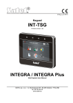
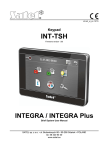
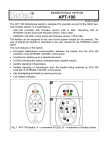
6. Operating the alarm system with LCD keypad
Fig. 1. VERSA-LCDM keypad (the VERSA-LCDM-WRL keypad differs only in some graphic
elements on its glass).
Fig. 2. VERSA-LCD keypad.
SATEL offers the following LCD keypads for VERSA IP control panels:
VERSA-LCDM – hardwired keypad,
VERSA-LCDM-WRL – wireless keypad,
VERSA-LCD – hardwired keypad.
SATEL
VERSA IP
7
The keypads are available in a variety of color options for the display and key backlight. The
color variant is indicated by the additional designation in the keypad name (e.g.
VERSA-LCD-GR – green display and keys backlight; VERSA-LCDM-WH – white display and
keys backlight).
6.1
6.1.1
LED
Keypads description
LEDs presenting partition and system state
Color
green
red
yellow
blue
Description
indicates the partition state (each partition has its own LED)
ON – partition is armed
blinking – exit delay countdown is running in partition
indicates alarm or alarm memory in the partition (each partition has its
own LED)
The way of presenting the information is shown graphically below.
The information is presented for 2 seconds and repeated ( – LED is
OFF;
– LED is ON). The higher position in the list means the higher
priority of the presented status:
– fire alarm,
– burglary alarm,
– warning alarm,
– tamper alarm,
– fire alarm memory,
– burglary alarm memory,
– warning alarm memory,
– tamper alarm memory.
blinking when the system requires user's attention (e.g. because of
a trouble or trouble memory)
The LED goes off, if one or both partitions are armed.
indicates the service mode
ON – the service menu is available on the keypad
blinking – the service menu is not available on the keypad (it is either
available on another keypad or has been hidden by the installer)
Information about the armed state can be extinguished after a time period defined by
the installer. Entering the code and pressing the
key will display again the
armed state information.
If the GRADE 2 global option is enabled by installer:
the
key,
LEDs indicate alarms only after entering the code and pressing the
blinking of the
LED means that there is a trouble in the system, some zones
are bypassed, or that there was an alarm.
When programming by means of the “step-by-step” method, the
the number of the current step (see p. 15).
and
When you are using the user menu or service menu, the
LED is:
blinking rapidly during navigation through the menus and submenus,
LEDs present
8
VERSA IP
SATEL
steady on after a function is started.
6.1.2
Display
The display provides a number of data, facilitating communication between the alarm system
and the user. The installer defines how the display will be backlit and selects the information
to be shown on the display screen.
The display can work in normal mode or in zone presentation mode (the modes being
toggled by means of the
key). When in the normal mode, the date and time (in installer
defined format) or the keypad name are presented in the upper line of the display. In the
zone presentation mode, symbols are displayed, showing the status of zones available in the
system (where the control panel settings do not provide for detector presence at a zone, the
status of the zone is not displayed). The numbers around the display correspond to the zone
numbers. The symbols illustrate the following zone states (the higher position on the list, the
higher priority of the presented state):
– inhibited (not displayed when armed),
[blinking] – isolated (not displayed when armed),
– long violated (not displayed when armed),
– no violations (not displayed when armed),
– first triggered alarm,
– tampered (2EOL type zone),
– violated,
– tamper memory (2EOL type zone),
– alarm memory,
– normal state.
If the global GRADE 2 option is enabled by the installer, switching the display over to
the zone status presentation mode (
key) is impossible.
Irrespective of the selected mode, the occurrence of specific events may result in the
following information being displayed (the higher position = the higher priority of the status
presented):
countdown of auto-arming delay,
countdown of entry delay,
countdown of exit delay,
alarm from zone – the message contains the name of zone which triggered the alarm and
remains displayed until the alarm is cleared (in case of alarm from several zones,
messages about successive alarms are displayed alternately every 2 seconds – use the
or
key to scroll them through),
alarm in partition – the message contains the name of partition where the alarm occurred
and remains displayed until the alarm is cleared (if there is alarm in both partitions,
messages about the alarm are displayed alternately every 2 seconds in the first and
or
key to scroll them through),
second partition – use the
there was a tamper and the service must be called in – the message is displayed until
trouble memory is cleared by a person using the service code (see: “Trouble memory and
clearing the trouble memory” p. 30).
If the GRADE 2 global option is enabled by the installer, the messages on alarms and
tampers are not displayed.
SATEL
6.1.3
VERSA IP
9
Keys
The keys bearing digits and letters enable entering the code, as well as data when the
keypad is being used.
Other functions of these keys and the basic function of the other keys are described below.
allow to trigger the medical (aux) alarm (press and hold down for 3 seconds)
allow to turn on/off the CHIME signal in the keypad (press and hold down for
3 seconds)
allow to toggle the LCD keypad display between the normal mode and the zone state
presentation mode (press and hold down for 3 seconds)
allow to:
arm in the full mode [if the system is disarmed and there is no alarm] or disarm
the system and clear the alarm [if the system is armed and/or there is an alarm]
(enter the code and press
)
trigger the panic alarm (press and hold down for 3 seconds)
allow to:
open the user menu (enter the code and press
)
trigger the fire alarm (press and hold down for 3 seconds)
allow to arm in the full mode (see “Arming”)
allow to arm in the night mode (see “Arming”)
allow to arm in the day mode (see “Arming”)
allow to:
disarm the system and clear the alarm (see “Disarming and alarm clearing”)
quickly check the partition state (press and hold down for 3 seconds)
6.1.4
Built-in proximity card reader
The VERSA-LCDM-WRL keypad has a built-in proximity card reader. The reader enables
arming/disarming and alarm clearing by means of proximity cards, proximity tags or other
125 kHz passive transponders.
6.1.5
Sound signaling
The installer can disable the sound signaling.
Beeps generated when operating
1 short beep – pressing any number key.
3 short beeps – confirmation of:
– starting the arming procedure (there is exit delay in the partition) or arming (there is no
exit delay in the partition),
– disarming and/or alarm clearing,
– selecting the partition which is to be armed or disarmed, or where alarm is to be cleared
– in such a case the keypad is waiting for the code to be entered,
– turning output off,
– turning off the CHIME in the keypad, using the
key,
– switching over the display from the normal mode to the zone status presentation mode,
and vice versa, by means of the
key.
10
VERSA IP
SATEL
4 short beeps and 1 long beep – confirmation of:
– turning output on,
– turning on the CHIME in the keypad, using the
key.
1 long beep – some zones are bypassed (when arming) or denial of arming (some zones in
the partition are violated or there is a trouble).
2 long beeps – incorrect code / card or pressing the
,
,
,
or
key, if not preceded by entering code or selecting a partition.
3 long beeps – refusal to carry out a command (the user does not have the required
authority level or the function is not available).
Beeps generated during programming
1 short beep – pressing any number key.
2 short beeps – entering the user menu, submenu or a function, or going to a next
programming step.
3 short beeps – end of timer parameters editing, exiting the service function on pressing the
key.
4 short beeps and 1 long beep – termination of the user function on pressing the
or quitting the service mode.
2 long beeps – exiting the function on pressing the
key,
key, or an unavailable function.
Events signaled by sounds
Only installer selected events are signaled.
Duration of the alarm signaling is to be defined by the installer.
If the GRADE 2 option is enabled by installer, the keypad will not signal by sounds any
new troubles and alarms.
5 short beeps – zone violation (CHIME).
Long beep every 3 seconds, followed by a series of short beeps for 10 seconds
and 1 long beep – countdown of exit delay (if the time is shorter than 10 seconds, only
the final sequence of short beeps will be generated).
A sequence of 7 beeps of diminishing duration, repeated every few seconds –
countdown of auto-arming delay.
2 short beeps every seconds – countdown of entry delay.
2 short beeps every 3 seconds – signaling a new trouble.
Short beep every 0.5 seconds – warning alarm.
Continuous beep – alarm.
Long beep every second – fire alarm.
6.2
Codes
Operating the alarm system by means of the keypad is possible after entering the code. Only
some functions can be run without the code being entered.
Do not make your code available to other people.
Using an incorrect code three times may:
trigger an alarm,
block the keypad for 90 seconds.
SATEL
6.2.1
VERSA IP
11
Factory default codes
By default, the following codes are preprogrammed in the control panel:
user 30 code: 1111
service code: 12345
The factory default codes should be changed before you start using your alarm
system (see: “Change own code”).
6.3
Arming
Completion of the steps below will start the arming procedure. The procedure ends when the
exit delay time elapses (if the countdown is completed successfully, the system becomes
armed – see also “Failure of arming procedure” p. 13). If the exit delay time is 0, the system
becomes armed instantly.
You can change the arming mode, which means you do not have to disarm the system to set
the partition to another arming mode. In the case of alarm, changing the arming mode or reactivating the same arming mode will result in clearing the alarm (it does not apply to the
quick arming mode).
The day/night arming modes are available if the installer has defined which zones are
to be active in this armed mode.
If exit delay is programmed for a partition, you can leave the partition through the exit
route without triggering alarm after the partition arming procedure has started. The
exception is when the partition is armed without exit delay.
6.3.1
Arming without partition selection
Enter the code, and then press:
- to arm in full mode,
- to arm in day mode,
- to arm in night mode.
The partitions to which you have access will be armed.
6.3.2
Arming with proximity card VERSA-LCDM-WRL
1. Press any key on the VERSA-LCDM-WRL keypad to activate it.
2. Bring the card close to the keys and hold it there for about 3 seconds. The partitions to
which you have access will be armed in full mode.
The reader in VERSA-LCDM-WRL keypad is enabled for 5 seconds after activating
the keypad.
6.3.3
Arming the selected partition
1. Indicate the partition which is to be armed (press one of the keys:
- partition 2).
- partition 1;
2. Select the arming mode (press one of the keys:
- full arming;
- day arming;
- night arming). Backlight of the keys will start blinking, which indicates that the
code must be entered.
3. Enter the code.
4. Press the
key or press again the key corresponding to the selected arming mode.
When the quick arming is available, the steps 3 and 4 are skipped.
12
VERSA IP
6.3.4
SATEL
Quick arming
The installer may permit arming without entering the code.
1. Indicate the partition(s) to be armed (press one of the keys:
partition 2;
or
- both partitions).
2. Select the arming mode (press one of the keys:
- night arming).
- full arming;
- partition 1;
-
- day arming;
You can switch the arming mode from the night mode to the full mode and from the
day mode to the full mode without entering the code. Otherwise, you will have to enter
the code – see “Arming the selected partition”.
The installer can configure the system so that the quick arming can be impossible, if
there is a violated zone in the partition, or a trouble has occurred in the system.
6.3.5
Arming without delay
When arming the system using one of the above mentioned methods, press and hold down
the arming mode selection key (
,
or
) for about 3 seconds. The system will
become armed without delay, i.e. the delayed zones will act as instant ones (without any
exit/entry delay time).
6.3.6
Information about bypassed zones
During an arming attempt you may get a message about bypassed zones in the partition. The
information will be displayed, if:
the control panel has been suitably configured by the installer,
you have the INSPECTION right.
The message is displayed in the following form:
“Bypassed zones 1=Arm 4=Bypasses” – if you have the ZONE INHIBITION right. You can:
– press the
key to cancel the arming,
– press the
key to proceed with the arming,
– press the
key to start the INHIBIT function (see: “Zone inhibiting” p. 25).
“Bypassed zones 1=Arm” – if you don’t have the ZONE INHIBITION right. You can:
– press the
key to cancel the arming,
– press the
key to proceed with the arming.
6.3.7
Denial of arming and forced arming
The installer can configure the control panel so that initiating the arming procedure is
impossible, if:
in the partition to be armed, at least one zone that must not be violated during arming (the
PRIORITY option has been enabled for the zone by the installer) is violated,
in the partition to be armed, at least one alarm zone is violated beyond the exit route,
there is trouble in the system.
If you have the INSPECTION right, you will be informed about the cause of refusal to arm the
system (the order of message descriptions corresponds to their priority):
“Zone [zone number] violat.” – a zone with enabled PRIORITY option is violated. If two or
more such zones are violated, the
indicator will be flashing on the display. To scroll
through the list of violated zones, use the
and
keys. You can:
– press the
key to cancel the arming,
SATEL
VERSA IP
13
– press the
key to inhibit the violated zone (you must have the ZONE INHIBITION
right). A message will be displayed, prompting you to confirm the command to inhibit the
zone (press
to inhibit the zone, or
to cancel inhibiting the zone).
The system can be armed after eliminating the cause of the zone violation, or after
bypassing the zone.
“Violated zones 1=Ok 2=Check” – an alarm zone outside of the exit route is violated. You
can:
– press the
key to cancel the arming,
– press the
key to force the arming,
– press the
key to check which zone is violated. If two or more such zones are
violated, the
indicator will be flashing on the display. To scroll through the list of
violated zones, use the
and
keys. If you have the ZONE INHIBITION
permission, you will be able inhibit the violated zone by pressing
. A message will
to
be displayed, prompting you to confirm the command to inhibit the zone (press
inhibit the zone, or
to cancel inhibiting the zone).
“Troubles 1=Ok 2=Check” – there is a trouble in the system. You can:
– press the
key to cancel the arming,
– press the
key to force the arming,
– press the
key to view the trouble log – the 7. SYSTEM
(see: “Checking the troubles / system state” p. 30).
STATE
function will start
Information on the forced arming is written into the event log.
6.3.8
Failure of arming procedure
The installer can configure the alarm system in such a manner that it will not be armed, if at
the moment of completing the exit delay countdown:
there is a violated zone in partition which was not violated when the arming procedure was
started,
there is a trouble which did not exist when the arming procedure was started.
If the arming has been forced, the control panel will ignore violations and troubles
which took place after starting the arming procedure.
6.4
Disarming and alarm clearing
Disarming and alarm clearing are carried out in the same way, the procedures being
interconnected. If the partition is armed and an alarm is triggered in it, then disarming will
also mean alarm clearing.
In order to clear the alarm without disarming the partition, arm again the partition in the
same mode (see: “Arming” p. 11).
6.4.1
Disarming and alarm clearing without partition selection
Enter the code and then press the
partitions to which you have access.
6.4.2
key. Disarming / alarm clearing will take place in the
Disarming and alarm clearing with a proximity card VERSA-LCDM-WRL
1. Press any key on the VERSA-LCDM-WRL keypad to activate it.
14
VERSA IP
SATEL
2. Bring the card close to the keys and move it away. Disarming / alarm clearing will take
place in the partitions to which you have access.
The reader in VERSA-LCDM-WRL keypad is enabled for 5 seconds after activating
the keypad.
6.4.3
Disarming and alarm clearing in selected partition
1. Indicate partition which is to be disarmed and/or where alarm is to be cleared (press one
of the keys:
- partition 1;
- partition 2).
2. Press the
key. Backlight of the keys will start blinking, which indicates that the code
must be entered.
3. Enter the code.
4. Press the
6.4.4
or
key.
Viewing the zones which triggered alarm
Having cleared the alarm, you can check which zones triggered the alarm (this does not
apply to the TMP zone of the control panel). The information will be available until viewing the
zones or arming the system.
1. Enter the code and press
.
2. The “View cleared zones? 1=Yes” will appear on the display. Press
3. The list of zones which triggered the alarm will be displayed.
4. Having viewed the list, press
6.5
.
(the user menu will be displayed).
Quick inspection of partition status
If such an option is provided by the installer, pressing and holding down the
key for
about 3 seconds will display information on the partition state (whether it is armed and what
type of arming mode is set). At the same time, the
LED will come on. In the upper line,
a message about the first partition state is displayed, and in the lower line – about the second
partition state.
To terminate the function of partition state presentation, press
function automatically after 2 minutes.
6.6
. The keypad will quit the
Triggering the alarm from keypad
The installer can permit triggering alarms from the keypad. To trigger an alarm, do the
following:
fire alarm – press
for approx. 3 seconds,
medical (auxiliary) alarm – press
for approx. 3 seconds,
panic alarm – press
for approx. 3 seconds. The installer defines whether the loud
panic alarm (setting off the loud alarm signal) or the silent panic alarm (without the loud
signal) will be triggered.
6.7
Turning the CHIME on /off
The CHIME is five short sounds by means of which the keypad will inform you e.g. that
a door / window is open, when the system is disarmed. The installer defines which zones of
the alarm system can trigger the CHIME and whether it can be turned on/off by the users.
Press and hold down
for about 3 seconds to turn on or off the CHIME signaling.
SATEL
6.8
VERSA IP
15
User menu
Enter the code and press
to get access to the user menu. The functions you can run
will be displayed. The list of available functions depends on your rights, as well as on the
state and configuration of the system.
In order to quit the function and/or user menu, press
. The keypad will quit the menu
automatically, if 2 minutes have elapsed since the last keypress.
6.8.1
Navigating through the menu and running functions
Using the arrow keys
and
keys, find the required submenu or function. The currently
1. Using the
selected submenu or function is indicated by the cursor on the left (the submenu
indicating cursor: ; the function indicating cursor: ).
2. Press
or
to open a submenu or run a function (use the
to the previous menu/submenu).
key to go back
Using the digit shortcuts
All submenus and functions are numbered. In order to enter a submenu, just press the key
with number corresponding to the submenu number. In order to start a function, press the
key with number corresponding to the function number, and then
. You can quickly start
the selected function by entering at once a sequence of some digits (corresponding to the
consecutive submenu numbers and the function number) and pressing
.
For example, to start the zone inhibiting function, enter the user menu and then press
, where:
- entering the 4. BYPASSES submenu,
- running the 1. INHIBIT function.
Remember that the sequence of digits which starts a function e.g. from the main menu
level will not start the same function from the submenu level.
6.8.2
“Step by step” programming method
LED status
Number of
programming step
1
2
3
4
5
6
7
8
9
10
Table 1. The manner of indicating the programming step
(
- LED OFF;
- LED ON).
In case of some functions (e.g. adding and editing users, configuring timers, etc.), the
programming is effected by using the “step by step” method. After calling the function and
16
VERSA IP
SATEL
selecting the item to be configured from the list, the first parameter available for programming
will be displayed. After pressing
, you will go on to programming another parameter (if
you have entered some changes, they will be saved). After all parameters have been
configured, you will either return to the selection list or exit the user menu, depending on the
function. The
and
LEDs of the first and second partition show the number of
programming step (see: table 1). Some programming steps may be sometimes not available.
6.8.3
Entering data
The changes entered will be saved after pressing the
the function without saving changes.
key. Use the
key to quit
Entering digits
To enter digits, use the numeric keys.
Entering hexadecimal characters
To enter digits, use the numeric keys, and to enter characters from A to F, use the
keys (keep pressing the key until the required character appears).
and
Entering names
The characters that can be entered by using the keys are presented in Table 2. Keep
pressing the key until the required character appears. Long press the key to display the digit
assigned to it.
Shown on the left side in the upper line of the display is information about the letter case:
[Abc], [ABC] or [abc] (it will be displayed after pressing any key and will be visible for a few
seconds after the last keystroke).
The
key moves the cursor to the right, and the
deletes the character on the left side of the cursor.
Key
!
?
'
`
a
d
g
j
m
b
e
h
k
n
c
f
i
l
o
2
3
4
5
6
p
q
r
s
t
u
v
w
x
y
key – to the left. The
Characters available after next keystroke
"
{
}
$ % & @ \
^
|
key
#
1
7
8
z
9
.
,
:
;
+
/
= _ < >
(
)
[
]
0
Table 2. Characters available when entering names. The upper case letters are available
under the same keys (to change the letter case, press
).
6.8.4
User functions list
Shown in square brackets are key sequences that enable calling the given submenu or
starting the given function from the main menu level. The functions that are only available
after entering the service code have been specially highlighted (white text against black
background). The access to other functions depends on the user rights. Highlighted with
SATEL
VERSA IP
17
a frame are the functions which are available or change the operating mode, if the GRADE 2
option has been enabled by the installer.
[1#] 1. Change code
changing own code
[2]
2. Users
[21#] 1. New user
adding new user
[22#] 2. Edit user
editing user
[23#] 3. Remove user
removing user
[3#] 3. Abort v.msg.
[4]
4. Bypasses
[41#] 1. Inhibit
inhibiting zones
[42#] 2. Isolate
isolating zones
[5#] 5. Event log
[6]
canceling telephone messaging
viewing events
[5#1#] 1. All
viewing all events
[5#2#] 2. Grade2 backup
viewing events required for Grade 2
6. Settings
[61#] 1. A-arm defer.
auto-arming deferment
[62#] 2. RTC clock
programming the clock
[63#] 3. Timers
programming the timers
[64#] 4. Tel. numbers
programming telephone numbers to be notified
[65#] 5. Msg.clr.codes
programming codes to acknowledge / clear messaging
[7#] 7. System state
checking troubles / checking partition, alarm, trouble status
[8#] 8. Control
controlling the outputs
[9]
[0]
9. Tests
[91#] 1. Zone test
starting zone test
[92#] 2. Output test
starting output test
[93#] 3. Wireless sig.
checking the level / quality of radio signal
[94#] 4. Manual MS tst
starting manual test transmission
[95#] 5. MS1 test
test of telephone reporting to station 1
[96#] 6. MS2 test
test of telephone reporting to station 2
[97#] 7. VERSA version
checking firmware version of control panel
[98#] 8. Expander ver.
checking firmware version of system modules
[99#] 9. Supply volt.
checking current supply voltage in modules
[90#] 0. Outputs reset
deactivating outputs / activating 21. DETECTORS RESETTING output
0. Service
[00#] 0. Service mode
starting service mode
[01#] 1. Start DwnlTEL
starting programming via telephone communicator
[03#] 3. Start DwnlUSB
starting local programming
18
VERSA IP
SATEL
[04#] 4. FinishDwnlUSB
finishing local programming
[05#] 5. Serv. access
defining service code access rules
[06#] 6. Access time
defining service code access time
[07#] 7. ETHM-1DloadX starting programming via Ethernet
6.9
Change own code
1. Enter the user menu and press in turn
2. Enter the new code, and then press
.
.
6.10 Users
There can be up to 30 users in the system. A person using the service code (installer
/ service technician), who is an additional user, has a special status, but his/her access can
be limited (see: “Defining the service access rules” p. 33 and “Defining the service access
time” p. 33).
6.10.1 Adding a user
1. Enter the user menu and press in turn
. Adding the user is effected by
the “step by step” method, hence the programming step number is presented on the
and
LEDs of the first and second partitions (see: page 15, Table 1).
You can press
to interrupt the procedure of adding a user. If the procedure is
interrupted in step 5 or a next one (the code, user schedule and partitions have been
already assigned to the user), the user will be added.
2. Step 2. Entering new user code. Information on the number of the user to be added is
presented in the display upper line. Enter the new user's code, and then press
.
3. Step 3. Selecting user schedule. Five installer defined schedules are available. The
schedule determines the user's rights and the default operating mode of the remote
control keyfobs assigned to the user (the keyfobs are added in subsequent steps). Press
the key bearing the digit corresponding to the schedule which is to be assigned to the
user. The name of selected schedule will appear in the lower display line. Press
to
confirm your selection.
SATEL
VERSA IP
19
Administrator
DURESS
Arm only
Simple
Usual
Schedule name and number
Right
1
2
3
4
5
Arming
Disarming
Alarm clearing
Telephone messaging clearing
Auto-arming defer
Zone inhibition
Zone isolation
Change access code
Users editing
Control
Programming
DOWNLOAD/SERWIS
Inspection
Tests
DURESS
INT-VG access
Table 3. Factory default settings of the user schedules. The installer can change the names
of schedules and assign other rights to them.
Using the DURESS right code will trigger a silent alarm, which is not signaled in any
way, but the alarm code will be sent to the monitoring station.
4. Step 4. Selecting partitions accessible to the user. Press the key
(partition 1),
(partition 2) or
(both partitions) to define the partitions to which the user is to
have access. Information on the selected partition(s) will appear in the lower display line.
to confirm your selection.
Press
5. Step 5. Adding 433 MHz keyfob. If the INT-RX-S, INT-RX or VERSA-MCU module is
connected to the control panel, the user may be assigned a 433 MHz keyfob. Press in
turn
and
(if a keyfob is to be assigned to the user) or
only (if no keyfob
is to be assigned to the user).
6. Step 5a. Selecting 433 MHz keyfob addition method. Press
(if the keyfob serial
number is to be entered) or press in turn
(if the serial number is to be read by
the device which supports the keyfobs during transmission).
7. Step 5b. Adding 433 MHz keyfob. Depending on the selected method:
– enter the keyfob serial number and press
,
– press twice any button on the keyfob (displayed messages will prompt you what to do).
Numbering of the buttons in 433 MHz keyfobs is described in section “Operating the
alarm system by means of keyfob” (p. 33).
20
VERSA IP
SATEL
8. Step 5c. Assigning function to 433 MHz keyfob button 1. Press
to confirm the
default function (defined by the installer in the user schedule) or enter the number of one
of the following functions, and then press
:
0. Not used
1. Zone 1 violation
2. Zone 2 violation
3. Zone 3 violation
4. Zone 4 violation
5. Zone 5 violation
6. Zone 6 violation
7. Zone 7 violation
8. Zone 8 violation
9. Zone 9 violation
10. Zone 10 violation
11. Zone 11 violation
12. Zone 12 violation
13. Zone 13 violation
14. Zone 14 violation
15. Zone 15 violation
16. Zone 16 violation
17. Zone 17 violation
18. Zone 18 violation
19. Zone 19 violation
20. Zone 20 violation
21. Zone 21 violation
22. Zone 22 violation
23. Zone 23 violation
24. Zone 24 violation
25. Zone 25 violation
26. Zone 26 violation
27. Zone 27 violation
28. Zone 28 violation
29. Zone 29 violation
30. Zone 30 violation
31. Arming partition 1 – full armed mode
32. Arming partition 1 – night armed mode
33. Arming partition 1 – day armed mode
34. Disarming / clearing alarm in partition 1
35. Arming partition 2 – full armed mode
36. Arming partition 2 – night armed mode
37. Arming partition 2 – day armed mode
38. Disarming / clearing alarm in partition 2
39. Arming partitions 1 and 2 – full armed mode
40. Arming partitions 1 and 2 – night armed mode
41. Arming partitions 1 and 2 – day armed mode
42. Disarming / clearing alarm in partitions 1 and 2
43. Loud panic alarm
44. Silent panic alarm
45. Fire alarm
46. Medical alarm
SATEL
VERSA IP
21
51. Output 1 activation
52. Output 2 activation
53. Output 3 activation
54. Output 4 activation
55. Output 5 activation
56. Output 6 activation
57. Output 7 activation
58. Output 8 activation
59. Output 9 activation
60. Output 10 activation
61. Output 11 activation
62. Output 12 activation
71. Output 1 deactivation
72. Output 2 deactivation
73. Output 3 deactivation
74. Output 4 deactivation
75. Output 5 deactivation
76. Output 6 deactivation
77. Output 7 deactivation
78. Output 8 deactivation
79. Output 9 deactivation
80. Output 10 deactivation
81. Output 11 deactivation
82. Output 12 deactivation
91. Output 1 switchover
92. Output 2 switchover
93. Output 3 switchover
94. Output 4 switchover
95. Output 5 switchover
96. Output 6 switchover
97. Output 7 switchover
98. Output 8 switchover
99. Output 9 switchover
100. Output 10 switchover
101. Output 11 switchover
102. Output 12 switchover
Contact the installer to obtain information on the zone types and output functions.
9. Step 5d. Assigning function to 433 MHz keyfob button 2. Proceed in the same way as
in Step 5c.
10. Step 5e. Assigning function to 433 MHz keyfob button 3. Proceed in the same way as
in Step 5c.
11. Step 5f. Assigning function to 433 MHz keyfob button 4. Proceed in the same way as
in Step 5c.
12. Step 5g. Assigning function to 433 MHz keyfob button 5 (two buttons pressed
simultaneously – see: “Operating the alarm system by means of keyfob” p. 33). Proceed
in the same way as in Step 5c.
22
VERSA IP
SATEL
13. Step 5h. Assigning function to 433 MHz keyfob button 6 (two buttons pressed
simultaneously – see: “Operating the alarm system by means of keyfob” p. 33). Proceed
in the same way as in Step 5c.
Pressing the
key between Step 5a and Step 5h will cancel the keyfob adding,
but will not terminate the user adding procedure.
14. Step 6. Adding APT-100 keyfob. If the ABAX wireless system controller is connected to
the control panel, the bidirectional APT-100 keyfob can be assigned to the user. Press in
turn
and
(if a keyfob is to be assigned to the user) or
only (if no keyfob
is to be assigned to the user).
15. Step 6a. Selecting APT-100 keyfob addition method. Press
(if the keyfob serial
number is to be entered) or press in turn
(if the serial number is to be read by
the ABAX wireless system controller during transmission).
16. Step 6b. Adding APT-100 keyfob. Depending on the selected method:
,
– enter the keyfob serial number and press
– press twice any button on the keyfob (displayed messages will prompt you what to do).
Numbering of the buttons and LEDs on the APT-100 keyfobs is described in section
“Operating the alarm system by means of keyfob” (p. 33).
17. Step 6c. Assigning function to APT-100 keyfob button 1. Proceed in the same way as
in Step 5c.
18. Step 6d. Assigning function to APT-100 keyfob button 2. Proceed in the same way as
in Step 5c.
19. Step 6e. Assigning function to APT-100 keyfob button 3. Proceed in the same way as
in Step 5c.
20. Step 6f. Assigning function to APT-100 keyfob button 4. Proceed in the same way as
in Step 5c.
21. Step 6g. Assigning function to APT-100 keyfob button 5. Proceed in the same way as
in Step 5c.
22. Step 6h. Assigning function to APT-100 keyfob button 6 (two buttons pressed
simultaneously: 1 and 5). Proceed in the same way as in Step 5c.
to confirm
23. Step 6i. Selecting confirmation for LED 1 in APT-100 keyfob. Press
the default method of confirmation (defined by the installer in the user schedule) or enter
the number of one of the following functions and then press
:
0. On
LED is on, when the control panel has acknowledged receiving
1. Output 1 state
2. Output 2 state
3. Output 3 state
4. Output 4 state
5. Output 5 state
6. Output 6 state
7. Output 7 state
8. Output 8 state
9. Output 9 state
10. Output 10 state
11. Output 11 state
12. Output 12 state
13. Arming: Partition 1
information on pressing a button
LED is on, when the selected output is active
LED is ON when partition 1 is armed
SATEL
VERSA IP
14. Arming: Partition 2
15. Arming: Partition 1 or 2
16. Arming: Partition 1 and 2
17. Partition 1 – Full arm
18. Partition 1 – Night arm
19. Partition 1 – Day arm
20. Partition 2 – Full arm
21. Partition 2 – Night arm
22. Partition 2 – Day arm
23. Partition 1 – Alarm
24. Partition 2 – Alarm
25. Partition 1 or 2 – Alarm
26. Trouble
LED is ON when partition 2 is armed
LED is ON when partition 1 or 2 is armed
LED is ON when partitions 1 and 2 are armed
LED is lit when partition 1 is armed in full mode
LED is lit when partition 1 is armed in night mode
LED is lit when partition 1 is armed in day mode
LED is lit when partition 2 is armed in full mode
LED is lit when partition 2 is armed in night mode
LED is lit when partition 2 is armed in day mode
LED is ON when there is alarm in partition 1
LED is ON when there is alarm in partition 2
LED is ON when there is alarm in partition 1 or 2
LED is ON when there is trouble in the system
255. NOT PRESENT
LED will not be used for confirmation
23
Contact the installer to obtain information on the zone types and output functions.
24. Step 6j. Selecting confirmation for LED 2 in APT-100 keyfob. Proceed in the same
way as in Step 6i.
25. Step 6k. Selecting confirmation for LED 3 in APT-100 keyfob. Proceed in the same
way as in Step 6i.
Pressing the
key between Step 6a and 6k will cancel the keyfob adding, but will
not terminate the user adding procedure.
26. Step 7. Adding proximity card. If a device provided with proximity card reader is
installed in the system, a proximity card can be assigned to the user. Press in turn
and
(if a proximity card is to be assigned to the user) or
only (if no proximity
card is to be assigned to the user).
27. Step 7a. Selecting card addition method. Press
(if the card code is to be
entered) or select the device, by means of which the card code will be read. Use the
and
keys to scroll through the list of devices. Having selected the device,
.
press
28. Step 7b. Adding proximity card. Depending on the selected method:
– enter the card code (see: “Entering hexadecimal characters” p. 16) and press
,
– bring the card twice close to the reader (displayed messages will prompt you what to
do). Remember that the card number will only be sent by the proximity card
arm/disarm device after the card is moved away from the reader.
Pressing the
key in Step 7a or 7b will cancel the card adding, but will not
terminate the user adding procedure.
29. Step 8. Giving name to user. Enter the user name (see: “Entering names” p. 16) and
press
.
6.10.2 User editing
1. Enter the user menu and press in turn
. User editing is effected by the
“step by step” method, hence the programming step number is presented on the
and
LEDs of the first and second partitions (see: page 15, Table 1).
24
VERSA IP
SATEL
2. Step 1. Selecting user whose data are to be edited. You can make your selection by
scrolling through the list of users by means of the
and
keys or entering the
user number. Having selected the user, press
.
You can press
to interrupt the procedure of editing a user. Any changes made in
the steps ended by pressing the
key will be saved.
3. Step 2. Changing user code. Proceed in the same way as when adding a new user.
4. Step 3. Selecting user schedule. Proceed in the same way as when adding a new user.
5. Step 4. Selecting partitions accessible to the user. Proceed in the same way as when
adding a new user.
6. Step 5. Editing 433 MHz keyfob. Press:
–
, if you want to move on to the next step,
–
and
in turn, if you want to add a keyfob (the procedure is similar to that for
adding a 433 MHz keyfob to a new user, however, if the user had a keyfob before, the
control panel, during assignment of functions to the buttons, will suggest the same
functions as were assigned to the removed keyfob),
–
and
in turn, if the user has a keyfob and you want to edit functions
assigned to the keyfob buttons (the procedure is similar to that for assigning functions
after a 433 MHz keyfob has been added to a new user),
–
and
in turn, if you want to remove a keyfob.
Removal of the keyfob does not erase its settings (functions assigned to the keyfob).
The installer can remove all the 433 MHz keyfobs and their settings by using the
REM.RX K-FOBS function (SERVICE MODE 2. HARDWARE 1. KPDS. & EXPS.
9. REM.RX K-FOBS).
7. Step 6. Editing APT-100 keyfob. Press:
–
, if you want to move on to the next step,
–
and
in turn, if you want to add a keyfob (the procedure is similar to that for
adding the APT-100 keyfob to a new user, however, if the user had a keyfob before,
the control panel, when assigning functions to the buttons and defining the rules of
confirmation, will suggest the same settings as for the removed keyfob),
–
and
in turn, if the user has a keyfob and you want to edit functions
assigned to the keyfob buttons (the procedure is similar to that for assigning functions
after an APT-100 keyfob has been added to a new user),
–
and
in turn, if you want to remove a keyfob.
Removal of the keyfob does not erase its settings (functions assigned to the keyfob
and rules of confirmation).
The installer can remove all the APT-100 keyfobs and their settings by using the
REM.ABAX KFBS function (SERVICE MODE 2. HARDWARE 1. KPDS. & EXPS. 8.
REM.ABAX KFBS).
–
and
in turn, if the user has a keyfob and you want to edit the rules of
confirmation (the procedure is similar as for defining the rules of confirmation after an
APT-100 keyfob has been added to a new user).
8. Step 7. Editing proximity card. Press:
–
, if you want to move on to the next step,
SATEL
–
VERSA IP
25
and
in turn, if you want to add a card (the procedure is much similar to
that for adding a card to a new user),
–
and
, if you want to remove a card.
9. Step 8. Editing user name. Proceed in the same way as when adding a new user.
6.10.3 Removing a user
1. Enter the user menu and press in turn
.
2. Select the user who is to be removed. You can make your selection by scrolling through
the list of users by means of the
and
keys or entering the user number.
Having selected the user, press
.
6.11 Canceling the telephone messaging
The telephone messaging can be cancelled together with alarm clearing, if such an
option is provided by the installer.
The telephone messaging is cancelled after acknowledgement of the voice messaging
(see: “Acknowledgement of voice messaging” p. 38).
Enter the user menu and press in turn
.
6.12 Zone bypassing
If a zone is not to trigger alarm, you can bypass it, when the partition to which the zone
belongs is disarmed. Zone bypassing is useful, for example, when you want to leave
a window open when the system is armed or when a detector connected to the zone is out of
order and sets off false alarms.
Zone bypassing reduces the level of protection. When bypassed, the zone may enable
the intruder to get inside the protected area despite the system being armed.
If a zone is bypassed because of its malfunctioning, call in the service technician
immediately to repair the defect.
For security considerations, the installer may reduce the number of zones that the user
will be allowed to bypass.
The zone bypassing functions can also be used to unbypass the zones (the zone inhibiting
function makes it also possible to unbypass an isolated zone, while the zone isolating
function makes it also possible to unbypass an inhibited zone).
6.12.1 Zone inhibiting
The inhibited zone will remain bypassed until disarming the partition it belongs to, or until
unbypassing the zone by the user.
If the zone belongs to two partitions and is only armed when both partitions are armed,
it will be unbypassed after disarming one of the partitions.
Enter the user menu and press in turn
. Shown in the upper line of the
display will be a message to inform you that the zone is bypassed, and in the lower line – the
and
keys. There is
zone name. You can scroll through the zone list using the
a symbol in the upper right corner of the display:
– zone is not bypassed,
– zone is inhibited,
26
VERSA IP
SATEL
– zone is isolated.
Press any number key to change the displayed symbol to one of the following symbols:
– the zone is to be inhibited,
– the zone is to be unbypassed.
If you want to see the status of all zones which you can inhibit/unbypass, press
or
. The numbers around the display enable identification of the zones. Use the
and
keys to move the cursor. To inhibit/unbypass a zone, hover the cursor over it and
press any numeric key. If you want to restore the previous way of presentation of the zone
list, press
or
.
Press
to quit the function. The zones will be inhibited/unbypassed.
6.12.2 Zone isolating
The isolated zone will remain bypassed until it is unbypassed by the user.
Enter the user menu and press in turn
. The way of indicating the zone
state and the procedure are identical to those used for inhibiting the zones, but pressing any
number key will change the displayed symbol to one of the following symbols:
– the zone is to be isolated,
– the zone is to be unbypassed.
6.13 Viewing the event log
Enter the user menu and press in turn
. The last event that occurred in the
system will be displayed. The event description includes the time of its occurrence, its name
and additional information, e.g. the partition in which the event took place, the zone which
caused the event, etc. The additional information appears automatically a few seconds after
the event is displayed. Press
or
for the additional information to be displayed
sooner. To scroll through the event log, use the
and
keys.
If the GRADE 2 option is enabled, two functions for viewing the events are available for
the installer in the user menu:
- all events saved to the control panel memory will be
displayed,
- events required by the EN 50131 Standard for Grade 2 will
be displayed.
6.14 Auto-arming deferment
Partition can be armed automatically by the timer on specific days at specific time. If the
installer defines the time by which the auto-arming is to be deferred, you can defer the
arming.
6.14.1 Simple auto-arming deferment
The installer defines whether the users will be allowed to use the simple auto-arming
deferment and whether they will be able to use the simple auto-arming deferment just once
or multiple times.
The simple auto-arming deferment is possible during the auto-arming delay countdown. The
keypad displays then a suitable message and can additionally emit a sound signal.
Press the
key twice to defer the auto-arming.
SATEL
VERSA IP
27
6.14.2 Auto-arming deferment by means of function
Enter the user menu and press in turn
.
6.15 Setting the system time and date
Enter the user menu and press in turn
will be displayed. Enter a new time, and then press
the new date and then press
.
. The currently programmed time
. The date will be displayed. Enter
6.16 Programming the timers
You can program 4 timers. The timers can control partition arming mode and outputs. The
timer compares the time with the control panel clock and executes the selected function at
the preset time.
The installer defines which outputs will be controlled by the timers.
1. Enter the user menu and press in turn
. The programming is effected
by using the “step by step” method, hence the programming step number will be
presented on the
and
LEDs of the first and second partitions (see: page 15, Table
1).
2. Step 1. Selecting timer to be programmed. Press in turn the suitable keys to select
a timer:
- timer 1,
- timer 2,
- timer 3,
- timer 4.
3. Step 2. Selecting parameters to be programmed. Press in turn the suitable keys to
select a parameter:
- weekly schedule,
- exception 1,
- exception 2,
- exception 3,
- exception 4,
- partition 1 arming mode,
- partition 2 arming mode.
Irrespective of the selected parameter, pressing the
will take you back to Step 2.
key in a subsequent step
6.16.1 Programming the weekly schedule
1. Step 3. Programming timer activation/deactivation time on Monday. Use the
and
keys to move the cursor. If you want, you can only program the activation or
deactivation time. Instead of the other parameter, enter the sequence 9999 then. Press
to go on to the next step.
2. Step 4. Programming timer activation/deactivation time on Tuesday. Proceed in the
same way as in Step 3.
3. Step 5. Programming timer activation/deactivation time on Wednesday. Proceed in
the same way as in Step 3.
28
VERSA IP
SATEL
4. Step 6. Programming timer activation/deactivation time on Thursday. Proceed in the
same way as in Step 3.
5. Step 7. Programming timer activation/deactivation time on Friday. Proceed in the
same way as in Step 3.
6. Step 8. Programming timer activation/deactivation time on Saturday. Proceed in the
same way as in Step 3.
7. Step 9. Programming timer activation/deactivation time on Sunday. Proceed in the
same way as in Step 3.
8. Step 10. Programming timer activation/deactivation time on every day of the week.
Proceed in the same way as in Step 3. After pressing
, you will be taken back to
Step 2.
6.16.2 Programming an exception
The exception is a period when the timer will be activated/deactivated at a different time than
provided for by the weekly schedule. The programming is carried out in the same way for
each of the four exceptions.
1. Step 3. Programming the date from which the exception will be valid. Enter the year
to confirm the data and go on to the
(only the two last digits), month and day. Press
next step.
2. Step 4. Programming the date to which the exception will be valid. Proceed in the
same way as in Step 3.
3. Step 5. Programming the timer activation/deactivation time when the exception is
valid. Enter the data in the same way as for programming the timer
activation/deactivation in the weekly schedule. After pressing
, you will be taken
back to Step 2.
6.16.3 Selecting the arming mode
1. Define whether and what arming mode is to be activated by the timer (press one of the
- full arming;
- night arming;
- day arming;
- timer does not
keys:
arm the partition).
2. Press
. You will be taken back to Step 2.
6.17 Programming the telephone numbers to be notified
1. Enter the user menu and press in turn
.
2. Press in turn the suitable keys to select the telephone number to be edited (the phone
numbers to which voice messaging is not enabled are only available to the installer):
- telephone 1,
- telephone 2,
- telephone 3,
- telephone 4,
- telephone 5,
- telephone 6,
- telephone 7,
- telephone 8.
3. Enter the telephone number (the available characters are presented in Table 4). You can
enter up to 16 characters. Some of the characters occupy two positions (a, b, c, d, # and
). If they are used, you can enter less characters than 16. In the upper line, on the right
side of the display, you can find information on the letter case: [ABC] or [abc] (it is
SATEL
VERSA IP
29
displayed after you press any key and remains on the screen for a few seconds after the
last keypress). Use the
and
keys to move the cursor. The
key clears
the character to the left of the cursor.
4. Press
to confirm the entered number.
key
1
Characters available after next keystroke
mode [ABC]
key
#
1
2
B
C
3
D
E
F
4
5
6
7
8
9
mode [abc]
#
2
a
3
d
b
c
4
5
6
7
8
9
0
0
Table 4. Characters available in the keypad when entering telephone numbers (to change the
letter case, press
key).
Special character
B
C
D
E
F
#
a
b
c
d
Function description
switch-over to pulse dialing
switch-over to tone dialing (DTMF)
waiting for additional signal
3 second pause
10 second pause
signal in DTMF mode
signal # in DTMF mode
other signals generated in DTMF mode
Table 5. Special character functions.
6.18 Programming codes to acknowledge / clear messaging
1. Enter the user menu and press in turn
.
2. Press in turn the suitable keys to select the telephone number for which the code to
acknowledge / clear voice messaging is to be defined (the phone numbers to which voice
messaging is not enabled are only available to the installer):
- telephone 1,
- telephone 2,
- telephone 3,
- telephone 4,
- telephone 5,
30
VERSA IP
SATEL
- telephone 6,
- telephone 7,
- telephone 8.
3. Enter a 4-digit code, and then press
.
6.19 Checking the troubles / system state
When the
LED is blinking, you can check what caused this signaling. Enter the user
menu and press in turn
. To scroll through the list, use the
and
keys.
6.19.1 Information on system state
If the GRADE 2 option is enabled by the installer, the following information will be displayed:
partition alarms,
alarms from zones,
bypassed zones,
troubles,
partition state (disarmed or arming mode).
The higher position, the higher priority of the state.
6.19.2 Trouble handling procedure
Each trouble poses a danger to proper functioning of the alarm system and should be
repaired as soon as possible. If necessary, consult the installer.
In the event of failure of the control panel processor system (HSE), when you have
exited the 7. SYSTEM STATE function by using the
key, the “Make VERSA panel
restart? 1=Yes” message will be displayed. Pressing the
key will restart the
control panel and repair the trouble.
6.19.3 Trouble memory and clearing the trouble memory
The installer defines whether only the current troubles are to be presented, or also those
which have already ended. The flashing letter “M” in the upper right corner of the display
means that the trouble has already ended.
You can clear the trouble memory after quitting the function:
1. Press
displayed.
to quit the function. The “Clear trouble memory? 1=Yes” prompt will be
2. Press
to clear the trouble memory (pressing another key will cancel clearing the
trouble memory).
If the SERVICE MESSAGE AFTER TAMPER ALARM option is enabled in the control panel,
only the installer can clear the tamper alarm memory.
6.20 Output control
Using the keypad, you can control the operation of devices connected to the outputs (e.g. to
raise/lower roller blinds/shutters, turn on/off lighting or heating, etc.). The installer defines
how the outputs should work (whether the output will be activated for a defined time, or it will
remain active until deactivated by the user, timer, etc.).
6.20.1 Quick control of outputs
The installer can assign outputs to the numeric keys and allow them to be quickly controlled
(without entering the code).
SATEL
VERSA IP
31
Quick activation of output
Press the key to which the controllable output is assigned, and then
.
Quick deactivation of output
Press the key to which the controllable output is assigned, and then
.
6.20.2 Controlling the outputs by means of function
Enter the user menu and press in turn
. The output number is shown in the upper
line of the display, and the output name in the lower line. You can scroll through the list of
keys. Information on the output state is shown in the
outputs by using the
and
upper right corner of the display:
– output is activated,
– output is deactivated.
Press
to activate the output, or
to deactivate the output.
If you want to see the status of all outputs you can control, press
or
. The
numbers around the display enable identification of the outputs. Use the
and
keys to move the cursor. Having hovered your cursor over the output, you can activate it by
pressing
or deactivate it by pressing
. If you want to restore the previous way of
presentation of the output list, press
or
.
6.21 Tests
6.21.1 Zone test
The function enables checking the system zones and detectors connected to them for proper
functioning.
You can test the zones for which the installer has programmed other wiring type than
NOT USED.
Zone violation during the test will not trigger the control panel reaction, as
preprogrammed for the zone.
When testing the zones, the keypad does not present the current zone state, but only
indicates whether or not the zone was violated during the test.
1. Enter the user menu and press in turn
.
2. Enter two digits to define the test duration (e.g. if the time is to be 5 minutes, press in turn
and
– the test may last from 1 to 15 minutes), and then press
. The
keypad will indicate the zones which can be tested, using the symbol
(the numbers
around the display enable identification of the zones).
3. Violate the selected zones (e.g. walking through the area supervised by the motion
detector or opening the window supervised by the magnetic contact). The keypad should
inform you that the zone has been violated (the zone symbol changes to ). Information
on the violation will be presented until the zone test is terminated.
4. The test will be terminated automatically after the defined time has elapsed. You can
.
terminate it earlier by pressing
6.21.2 Output test
The function makes it possible to check proper functioning of the system outputs as well as
devices connected to them.
You can always test 12 outputs.
32
VERSA IP
SATEL
1. Enter the user menu and press in turn
. The keypad will present the
state of outputs in the upper line of the display ( – output inactive; – output active).
The name of output over which the cursor is currently situated is displayed in the lower
line. The
and
keys allow moving the cursor.
2. Press
to activate the output, or
3. Press
to quit the function.
to deactivate the output.
6.21.3 Checking the level / quality of radio signal
The function allows you to check:
the quality of radio signal received by the controller from 433 MHz wireless detectors (if the
VERSA-MCU controller is connected to the control panel),
the level of radio signal received by the controller from ABAX wireless devices (if the
ABAX system controller is connected to the control panel).
Enter the user menu and press in turn
. In the lower line of the display, the
information on signal level / quality will be shown. The upper line displays the name of zone
to which the wireless device is assigned.
Use the arrow keys to scroll through the list.
6.21.4 Starting the manual test transmission
Enter the user menu and press in turn
. A “Manual reporting test” event will
be saved to the control panel memory. The event code will be sent to the monitoring station.
6.21.5 Telephone reporting test
Enter the user menu and press in turn
(test of telephone reporting to
Station 1) or
(test of telephone reporting to Station 2). Messages with
information on the currently realized operations will appear on the display. This allows
problems, if any, to be diagnosed.
6.21.6 Checking the firmware version of control panel
Enter the user menu and press in turn
firmware version and build date will be displayed.
. Information on the control panel
6.21.7 Checking the firmware version of modules
Enter the user menu and press in turn
. Information on the firmware of
module with the lowest address will be displayed: the module name in the upper line, and the
firmware version and build date in the lower line. You can scroll through the list of modules
and
keys. In the case of the built-in Ethernet module, pressing the
using the
or
key will display additional information (IP address, MAC address, individual
identification number for the purpose of communication via the SATEL server [ID]).
6.21.8 Checking the current supply voltage in modules
Not all modules provide information on the current voltage.
Enter the user menu and press in turn
. Information on supply voltage of
the lowest address module will be displayed. To scroll through the list, use the arrow keys.
6.21.9 Outputs reset
Use the function to:
deactivate 5. “DURESS” ALARM, 14. CHIME or 15. CONTROLLED function outputs (if the cutoff time equal to 0 is programmed by the installer for such an output, the output can only
be deactivated in this manner),
SATEL
VERSA IP
33
deactivate for 16 seconds the 11. FIRE DETECTORS POWER SUPPLY function output (to clear
the alarm memory of fire detectors),
activate the 21. DETECTORS RESETTING function output.
Enter the user menu and press in turn
.
6.22 Service
The functions related to control panel programming (starting local or remote programming)
are described in the PROGRAMMING manual.
6.22.1 Defining the service access rules
Enter the user menu and press in turn
. In the upper line of the display, the
function name will be presented, and in the lower one – the first of the available options. You
can scroll through the list using the
and
keys. The following symbol is situated in
the upper right corner of the display:
– option is enabled,
– option is disabled.
Press any number key to enable/disable the option.
If you want to see the status of all options, press
or
. The numbers around the
display allow the options to be identified. Use the
and
keys to move the cursor.
To enable/disable an option, hover the cursor over it and press any numeric key. If you want
or
.
to restore the previous way of presentation of the list of options, press
Press
to confirm the changes made and quit the function.
Description of the options
The order of describing the options corresponds to their numeration in the keypad.
Permanent access – if the option is enabled, the service code can be used to get access to
the alarm system at all times.
If the alarm system is to meet requirements of the EN 50131 standard for
Grade 2, the service code access should be time limited.
Edit users – when the option is enabled, the person using the service code can add, edit and
remove users.
Arm/Dis/Clr/Bps – when the option is enabled, the person using the service code can arm
and disarm the system, clear alarms, and bypass zones (inhibit or isolate).
6.22.2 Defining the service access time
The function is available when the PERMANENT
service access rules”).
ACCESS
option is disabled (see: “Defining the
Enter the user menu and press in turn
. The number of remaining hours
will be displayed, during which the access to the alarm system is still possible by using the
service code. Enter a new value from the range of 0 to 255 hours and press
.
7. Operating the alarm system by means of keyfob
The alarm system can be operated by means of keyfobs, if the 433 MHz keyfobs receiver
expansion module (INT-RX-S / INT-RX), 433 MHz wireless system controller (VERSA-MCU)
or ABAX wireless system controller (ACU-120 / ACU-270 / ACU-100 / ACU-250) is
connected to the control panel.
34
VERSA IP
SATEL
The user can have two keyfobs:
433 MHz keyfob – supported by the 433 MHz keyfobs receiver expansion module or 433
MHz wireless system controller,
APT-100 bidirectional keyfob – supported by the ABAX wireless system controller.
A single keyfob enables up to 6 functions to be executed. The list of functions assigned to the
buttons / combination of buttons should be obtained from the person who configured the
keyfob settings when adding / editing a user. In the case of APT-100 keyfob, that person
should also provide information about functionality of the LEDs. The keyfob LEDs can be
used to confirm execution of functions, as well as to indicate the system status (pressing
a button on the APT-100 keyfob is accompanied by the LEDs flashing rapidly three times,
and in a little while the LED(s) may come on for 3 seconds to provide information).
The installer can configure the alarm system so that the sirens connected to the
system outputs can inform the user about the following events:
1 tone – starting the arming procedure (which is equivalent to arming, if the exit delay
has not been programmed),
2 tones – disarming,
4 tones – alarm clearing,
7 tones – arming is not possible, or the arming procedure has failed.
Tone duration is approx. 0.3 seconds.
Fig. 3. APT-100 keyfob (gray enclosure). A – numeration of LEDs. B – numeration of keyfob
buttons (button 6 – pressing buttons 1 and 5 simultaneously).
SATEL
VERSA IP
35
Fig. 4. T-4 keyfob [433 MHz keyfob]. A – numeration of keyfob buttons (button 5 – pressing
buttons 1 and 2 simultaneously; button 6 – pressing buttons 1 and 3 simultaneously).
Fig. 5. MPT-300 keyfob [433 MHz keyfob] (black enclosure). A – numeration of keyfob
buttons (button 5 – pressing buttons 1 and 2 simultaneously).
7.1
Denial of arming
The information given below is not applicable, if the keyfob button controls arming
zone.
The installer can program the control panel so that arming by means of keyfob is not possible
when:
in the partition to be armed, at least one zone that must not be violated during arming (the
PRIORITY option has been enabled for the zone by the installer) is violated,
in the partition to be armed, at least one alarm zone is violated beyond the exit route,
there is trouble in the system,
there is low battery in the keyfob.
In such a situation, to arm the system, you must either eliminate the cause that prevents
arming, or force the arming.
The installer should see to it that the user is effectively notified about the denial of
arming the system.
36
7.1.1
VERSA IP
SATEL
Forced arming
1. After an attempt to arm the system from the keyfob has failed, approach the keyfob, enter
the code and press
.
2. A message will appear on the display indicating why the arming has been denied. If the
message includes the “1=Ok” phrase, you can press the
key to force the arming.
3. Press again the keyfob button to which the arming function is assigned.
Information on the forced arming is written into the event log.
7.2
Failure of the arming procedure initiated from keyfob
The information given below is not applicable, if the keyfob button controls arming
zone.
The installer can configure the alarm system in such a manner that it will not become armed,
if at the moment the exit delay countdown ends:
there is a violated zone in partition which was not violated when the arming procedure was
started,
there is a trouble which did not exist when the arming procedure was started.
The installer should see to it that the user is effectively notified of the failure of
procedure to arm the system initiated from the keyfob.
In the event of forced arming the control panel will ignore violations and troubles that
occur after the start of the arming procedure.
8. Operating the alarm system by telephone
You can operate the alarm system by using a touch-tone (DTMF) telephone. The voice menu
makes the operation an easy job. To access the voice menu, call the phone number of the
control panel.
The installer can make the option of operating the system by phone conditional on the
partition state (the operation being only possible when the selected partitions are
armed).
8.1
Starting the operating by telephone
1. Call the control panel phone number. After the call is received, you will hear three short
beeps.
The installer can configure the control panel in such a manner that the telephone
communicator will only go off hook after the recall. If this is the case, call the number,
but hang up after the number of rings which has been set by the installer. Call again
within three minutes. The call will be received.
2. Enter the code from the telephone keypad and confirm by pressing #. 4 short beeps
followed by 1 long beep will confirm you have got access to the interactive voice menu. If
your code does not authorize you to get access, you will hear three long beeps in the
headset. If the code is incorrect, you will hear two long beeps in the headset.
After a wrong code is entered three times, the control panel will hang up and for the
next 90 seconds it will be impossible to establish connection with the control panel.
SATEL
VERSA IP
37
3. Messages of the interactive voice menu will be played back. They will inform you which
telephone keys you should use to be able to operate the control panel.
8.2
Voice menu
The structure of voice menu is shown below. Pressing the * key will always take you back to
the main menu.
1 – macros [you can run a macro, or an installer defined sequence of actions which is to be
executed by the control panel]
enter the macro number and press # (if only one macro is available, this step will
be skipped)
1 – execute
7 – execute despite obstacles
0 – another macro
# – next macro
* – main menu
2 – partitions [you can play back information on the state of partition, arm / disarm the
partition, clear alarm in the partition]
enter the partition number and press # (if only one partition is available, this step
will be skipped)
1 – arm in full mode
2 – arm in night mode
3 – arm in day mode
6 – disarm
7 – arm despite obstacles
9 – clear alarms
0 – another partition
# – next partition
* – main menu
3 – listen [if the INT-AVT terminal is connected to the control panel, you can use the listen-in
function and talk to the people staying in the premises]
2 – bidirectional
3 – loud
6 – quietly
* – main menu
4 – zones [you can play back information on the state of zone, bypass/unbypass the zone]
enter the zone number and press # (if only one zone is available, this step will be
skipped)
1 – inhibit
2 – isolate
6 – unbypass
38
VERSA IP
SATEL
0 – another zone
# – next zone
* – main menu
5 – alarms [you can play back information on the alarms, clear alarms]
9 – clear alarms
* – main menu
7 – troubles [you can play back information on the troubles, clear trouble memory]
8 – make system restart
9 – clear troubles memory
* – main menu
8 – outputs [you can play back information on the state of 15. CONTROLLED function output,
activate or deactivate the output]
enter the output number and press # (if only one output is available, this step will
be skipped)
1 – switch on
6 – switch off
0 – another output
# – next output
* – main menu
8.3
Ending the operating by telephone
1. Press * key.
2. Press in turn the 0# keys. The control panel will go on-hook.
The control panel will goes on hook automatically after one minute of idle state.
9. Acknowledgement of voice messaging
A special 4-digit code is used to acknowledge messaging (see: “Programming codes to
acknowledge / clear messaging” p. 29). Having received voice messaging, enter the code
from the telephone keypad. The messaging acknowledgement will cancel telephone
notification of the event. The installer can configure the control panel so that the user, after
acknowledgement of voice messaging, should automatically get access to the interactive
voice menu (see: “Operating the alarm system by telephone” p. 36).
10. VERSA Control application
The VERSA Control is a mobile application that allows you to remotely operate your alarm
system, i.e.:
arm / disarm the system or clear alarm,
bypass / unbypass the zones,
control the outputs,
view the event log,
SATEL
VERSA IP
39
view the troubles.
Additionally, the application can provide information on the alarm system events by using
push notifications.
You can download the application from the internet stores: “Google play” (Android system
devices) or “App Store” (iOS system devices).
Fig. 6. VERSA Control application: configuring the control panel settings.
Having installed the application:
enter the name of control panel (to enable identification of the control panel when using
the application),
enter the MAC address of control panel (the hardware address of built-in Ethernet
communication module),
enter the ID number of control panel (the individual identification number for the purpose of
communication via the SATEL server),
enter the user code (which will be used when operating the control panel by means of the
application),
40
VERSA IP
SATEL
select an icon for the control panel (to facilitate identification of the control panel when
using the application),
enable / disable the push notifications of the alarm system events (if you enable the push
notifications, select the events about which you want to be informed).
You can check the MAC address and ID by running the EXPANDER VER. function in the
keypad (see: “Checking the firmware version of modules” p. 32).