1
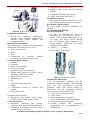
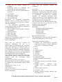
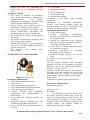
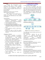
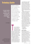
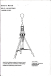
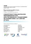
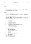
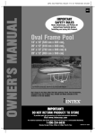
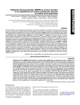
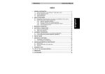
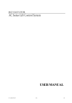
Journal of Global Trends in Pharmaceutical Sciences Review Article Available online at www.JGTPS.com ISSN: 2230-7346 Journal of Global Trends in Pharmaceutical Sciences Volume 5, Issue 1, pp-1450-1459, January-March 2014 A REVIEW ON QUALIFICATION OF AUTOCLAVE, RMG, FBD, CONE BLENDER, TABLET COMPRESSION MACHINE B.Venkateswara Reddy*1, B.Rasmitha Reddy1, K.Navaneetha1, K.Venkata Ramana Reddy2 1 St.pauls College of Pharmacy, Turkayamjal, R.R (Dist) -501510 2 Sree Datta Institute of Pharmaceutical sciences, Sheriguda, R.R (Dist)-501510 E-mail: [email protected] Journal of Global Trends in Pharmaceutical Sciences ABSTRACT Validation is one of the important steps in achieving and maintaining the quality of the final product batch after batch. Without equipment, we cannot manufacture a product. If equipment is validated, we can ensure that our product is of the best quality. Validation of the equipment is called the Qualification. To manufacture different types of dosage forms, different equipments are used. Here, this article concentrates on the equipment qualification for RMG, FBD, and Blender & Compression Machine. It gives in detail, qualification steps of the equipment which is used for manufacturing process through wet granulation Keywords: Validation, Equipment Qualification, RMG, FBD, Blender & Compression Machines. INTRODUCTION: In manufacturing facilities, validation test procedures are used to validate equipment and processes that may influence product quality. The tests for validation are used in accordance with approved written qualification procedures. All necessary activities and responsibilities for the qualification and validation are controlled and specified in this Validation Master Plan. Every step of the described validation program for facilities, equipment, processes, process controls, and cleaning is in accordance with the current European Community Guidelines for GMP and FDA, and the cGMP guideline for finished pharmaceutical manufacturers DEFINITION: Validation may be defined as “Establishing documented evidence which provides a high degree of assurance that a specific process will consistently produce a product meeting its pre-determined specifications and quality attributes.” It has Address for correspondence B. Venkateswara Reddy* St.pauls College of Pharmacy, Turkayamjal, R.R (Dist) -501510 been made mandatory by the regulatory bodies to prove the safety, efficacy, purity & effectiveness of the drug product, medical devices & biologics in the market place & health system. IMPORTANCE OF VALIDATION Increased throughput Reduction in rejections and reworking Reduction in utility costs Avoidance of capital expenditures Fewer complaints about process-related failures Reduced testing in-process and in finished goods More rapid and reliable start-up of new equipment Easier scale-up from development work Easier maintenance of equipment Improved employee awareness of processes More rapid automation EQUIPMENT QUALIFICATION Qualification: Action of proving and documenting that equipment or ancillary systems are properly installed, work correctly, and actually lead to the expected results. Qualification is part of validation, but B. Venkateswara Reddy et al/JGTPS/Volume 5, Issue 1, January-March 2014 1450 Journal of Global Trends in Pharmaceutical Sciences the individual qualification steps alone do not constitute process validation. 1. Design Qualification (DQ) 2. Installation Qualification (IQ) 3. Operational Qualification (OQ) 4. Performance Qualification (PQ) 5. Maintenance Qualification (MQ) Who should do Equipment Validation? : The vendor or the user has the ultimate responsibility for the accuracy of the analysis results and also for equipment qualification. DQ should always be done by the user. While IQ for a small and low cost instrument is usually done by the user, IQ for large, complex and high cost instruments should be done by the vendor. OQ can be done by either the user or the vendor. PQ should always be done by the user because it is very application specific, and the vendor may not be familiar with these. As PQ should be done on a daily basis, this practically limits this task to the user. Design Qualification (DQ): "Design qualification (DQ) defines the functional and operational specifications of the instrument and details for the conscious decisions in the selection of the supplier". The steps that should be considered for inclusion in a design qualification. Description of the analysis problem, Description of the intended use of the equipment, Description of the intended environment, Preliminary selection of the functional and performance specifications, Preliminary selection of the supplier, Final selection of the equipment, Final selection of the supplier, Development and documentation of final functional and operational specifications, Installation Qualification (IQ): “Installation qualification establishes that the instrument is received as designed and specified, that it is properly installed in the selected environment, and that this environment is suitable for the operation and use of the instrument.” The qualification involves the coordinated efforts of – The vendor. The operating department. The project team (which provide input into the purchase, installation, operation and maintenance of the equipment). Operational Qualification (OQ): "Operational qualification (OQ) is the process of demonstrating that an instrument will function according to its operational specification in the selected environment”. The proper operation of equipment is verified by performing the test functions specified in the protocol. A conclusion is drawn regarding the operation of equipment after the test functions are checked and all data has been analyzed. Following are the contents of equipment operation qualification: 1. Application S.O.P’s, 2. Utilization List, 3. Process Description, 4. Test Instrument Utilized To Conduct Test, 5. Test Instrument Calibration, 6. Critical Parameters, 7. Test Function (List), 8. Test Function Summaries. Performance Qualification (PQ): "Performance Qualification (PQ) is the process of demonstrating that an instrument consistently performs according to a specification appropriate for its routine use ". PQ should always be performed under conditions that are similar to routine sample analysis. PQ should be performed on a daily basis or whenever the equipment is being used. In practice, PQ can mean system suitability testing, where critical key system performance characteristics are measured and compared with documented. RAPID MIXER GRANUALATOR 1. Homogenous mixing of dry & wet powders, deaglomeration of wet mass and fast dispersion of binding agent. 2. Dust free, high free flowing dosing particles, high uniformity of granule size. 3. Frequency control for bottom driven Impeller Mixer with 3 or 4 blades with exclusive scrape side design and Chopper positioned to make granules. Installation Qualification: • An IQ establishes confidence that the equipment is properly installed. The installation must meet the manufacturer's specified guidelines, along with design changes at installation. Also the supporting electrical utilities must meet all electrical codes. B. Venkateswara Reddy et al/JGTPS/Volume 5, Issue 1, January-March 2014 1451 Journal of Global Trends in Pharmaceutical Sciences Figure 4: Rapid mixer granulator Equipment identification: Record the equipment identification number, with equipment manufacturer, purchase order, model number, and equipment number. Required Documentation: The manufacturers operation and maintenance manual and SOPs that cover the set up. Utility requirements Power Water Compressed air, spraying, impeller movement, pneumatic discharge port. Calibration Requirements: Ammeter Voltmeter Water pressure gauge Air pressure gauge Equipment major specifications: Mixing bowl material of contact, surface finishing, dimensions, capacity. Motors two are required Discharge port Lid Liquid air dispersing system Nozzle Components coming in contact with product Lubrication/ filter Equipment Safety Features: Emergency stop button, barrier guard, electrical inter locking system, alarms Control Functions: Regulators, discharge port opening, spraying button Operational Qualification: Calibration requirements for temp, timer, pressure gauges, ammeter. Equipment control functions: Impeller, timer, bowl on/off & slow/fast buttons. Emergency, discharge port on/off Alarm, wash down walls on/off Equipment operation: On empty the impeller should run at low speed and also check direction and speed. Performance Qualification: By using placebo max/min conditions are verified FLUIDIZED BED DRYER Design Qualification: In FBD, the fluidizing air stream is introduced by a fan or blower. The air is heated to the required temperature in an air heater and flows upward through the wet materials, which contained in a drying chamber fitted with a wire mesh supported at the bottom. Capacity : 5-200kg Drying time: 20 to 40 min Figure 5: Fluidized bed dryer Installation Qualification • An IQ establishes confidence that the equipment is properly installed. The installation must meet the manufacturer's specified guidelines, along with design changes at installation. Also the supporting electrical utilities must meet all electrical codes. Verify approved purchase order. Verify invoice. Check manufacturer and supplier. Verify model number and serial number. Check for any physical damage. Confirm location and installation requirements per recommendation of manufacturer. B. Venkateswara Reddy et al/JGTPS/Volume 5, Issue 1, January-March 2014 1452 Journal of Global Trends in Pharmaceutical Sciences Verify that the utilities required are available. Installation shall be conducted per instructions provided in the manual. Ensure that all relevant documentation is received: User manual Maintenance manual List of change parts Electrical drawings Instruments for measuring temperature, humidity, time, air volume and pressure, as well as recording devices for these variables, should be calibrated. Air temperature distribution Place several thermocouples at different locations in an empty fluid bed drier, e.g.: Inlet air channel below product container mesh bottom Product container Below filter bag Above filter bag Exhaust air channel Measure the temperatures, letting in air of a constant temperature (e.g., 60°C). Inlet air installation Delay time for achieving constant air conditions Determine, by use of a thermocouple and hygrometer, the necessary delay time required at an adjusted inlet air temperature (in relation to drying processes) for reaching constant air conditions. Determine these figures for the first use of the equipment at the working day, as well as for further use of the equipment at the same working day. Also calculate from the obtained data the water content of the inlet air (g water per kg air) and compare with the previously fixed requirements. Microbiological quality of the inlet air Determine, by use of a bio test RCS centrifugal air sampler, the microbiological quality of the inlet air. Sampling time 5 min = 8:1 air Requirements 200 CFU/m inlet air Influence of weather on inlet air conditions Inlet air installation Delay time conditions for achieving constant air Procedure Determine, by use of a thermocouple and a hygrometer, the necessary delay time required at an adjusted inlet air temperature (in relation to granulating processes) for reaching constant air conditions. Determine these figures for first use of the equipment at the working day, as well as for further use of the equipment at the same working day. Also calculate from the obtained data the water content of the inlet air (g water/kg air) and compare to the requirements. Equipment identification: Record the Equipment identification number Equipment manufacturer Purchase order Model number Equipment number Required documentation: The manufacturers operation and maintenance manual and SOPs that cover the set up. Equipment Utility Requirements: Compare the manufacturer's specified requirements to their as found conditions at the time of qualification testing. Power Steam Compressed air Calibration Ammeter Air/ water Pressure gauge Temperature gauge Major component specifications: Motor Fan: mfg, location, no of blades, rotation, capacity Ducting systems : material, type, welding, type of welding, no of weld spots Heater: voltage/ capacity Air heaters: coils Product container: housing, material, type of discharge port. B. Venkateswara Reddy et al/JGTPS/Volume 5, Issue 1, January-March 2014 1453 Journal of Global Trends in Pharmaceutical Sciences Equipment Safety Features: Barrier guard, alarm, emergency stop button, interlock with housing, positive pressure differential with flow regulators for fluid air regulation Positive high temperature alarm device Control functions: Process control like temperature, timer on/off bath, product discharge port buttons, filter bag, cleaning button Operational Qualification An OQ evaluation should establish that the equipment can operate within specified tolerances and limits. Verify alarm control. Perform calibration requirements, identified in the manual or established by the validation team. Operate the equipment at low, medium, and high speed per operations manual to verify the operating control. Verify that all switches and push buttons are functioning properly. Establish procedures for operation, maintenance, and calibration. Establish training program for relevant staff. Procedure Run three batches of each product and analyze for: Active ingredient homogeneity Moisture content Particle size distribution Percentage fines Tap density Based on these data try to fix a drying end point of the process (e.g., correlation between moisture content of the product and the product bed temperature). Calibration requirements: All the critical instruments on the equipment must be calibrated with calibration procedures. The equipment’s calibrated are temperature probes, pressure gauges for air/steam, timer, air flow rate and volume. Equipment control functions In this the ON/Off switches and discharge port are verified and also the LED buttons. Equipment Operation: 1. Drying cycle 2. Air flow 3. High temp 4. Filter test 5. feeding inlet/outlet 6. air volume 7. damper control 8. humidity control 9. drying time All these parameters are recorded before operation Performance Qualification After the equipment proper installation it's functioning and operating parameters must be verified. Calibrated equipment like hydrometer, temp probes, air flow monitors are required. Using placebos the PQ is verified The drying cycle parameters are fed charge at min& max load. As drying proceeds check temp, RH, fluidization pressure, differential air pressure parameters, after drying timer is set back to “O” to stop. All these parameters are recorded before operation. After drying the product check weight and also sampling is done at varied time and location. Test Functions 1. Perform Installation Qualification. Verify equipment identification, required documents, utilities, manual, and drawings. 2. Perform general operational controls verification testing. pressure, timer operations, circulation air flow, exhaust Verify calibration requirements. 3. Operate system throughout the range of operating design specifications or range of intended use. Verify switches and pushbuttons, open-door leaks, differential air flow, and high-temperature limit. 4. Verify that all safety devices are operating as specified in the manual. 5. Verify that recommended lubricants are used during machine operation. 6. Perform controller security challenges to verify that specified parameters cannot be altered without appropriate supervisory control. 7. Perform studies to check the moisture removal on each product as per SOP. B. Venkateswara Reddy et al/JGTPS/Volume 5, Issue 1, January-March 2014 1454 Journal of Global Trends in Pharmaceutical Sciences 8. Perform the study for establishing the drying time as per acceptable moisture level. Acceptance Criteria 1. The system is installed in accordance with design specifications, manufacturer recommendations, and cGMPs. Instruments are calibrated, identified, and entered into the calibration program. 2. General alarms and controls operate in accordance with design specifications. 3. The system operates in accordance with design specifications throughout the operating range or range of intended use. 4. The safety devices operate as specified in the manual. 5. The quality of lubricants is adequate, and their storage is dry and cool. 6. Unauthorized changes to cycle parameters must not be allowed without supervisory control or password. 7. The moisture level should meet specifications. VALIDATION OF CONE BLENDER Figure 6: Cone blender Installation Qualification: Verify approved purchase order. Verify invoice. Check manufacturer and supplier. Verify model number and serial number. Check for any physical damage. Confirm location and installation requirements per recommendation of manufacturer. Verify that the required utilities are available. Installation shall be conducted per the instructions provided in the manual. Ensure that all relevant documentation is received: User manual Maintenance manual List of change parts Electrical drawings Mechanical drawings Calibration of the control and recording equipment: Instruments for measuring temperature, pressure, time, mixing chamber slope, and mixing velocity, as well as recording devices for these variables, should be calibrated. Operational Qualification: Verify alarm control. Perform calibration requirements, identified in the manual or established by the validation team. Operate the equipment at low, medium, and high speed per operations manual to verify the operating control. Verify that all switches and push buttons are functioning properly. Establish procedures for operation, maintenance, and calibration. Establish training program for relevant staff. Net capacity of the mixing chamber: Procedure Fill the mixing chamber with reweighed quantities of water. The available net capacity should be equal to the supplier specification. Mixing or stirring velocity: Measure velocity three times at low, medium, and high speed and compare the average and deviation from the average of the single measurements with the supplier specification. Requirements Compliance with the supplier specification Performance Qualification: Product homogeneity: Mixing process: Procedure: Fix the mixing or stirring velocity, load the mixer with the product and switch the mixer on. After previously fixed intervals, the mixer should be switched off and samples should be taken from different locations of the product surface. The samples should be analyzed for their active content. B. Venkateswara Reddy et al/JGTPS/Volume 5, Issue 1, January-March 2014 1455 Journal of Global Trends in Pharmaceutical Sciences Unloading: Procedure: After determination of the suitable mixing time to achieve product homogeneity, the influence of the unloading process on the homogeneity should be evaluated. Samples should be taken and sent to QC for analysis. Requirements: Homogeneity should remain consistent. Water content of the product: Take samples of the product prior to mixing, after mixing, and after unloading (begin, mid, end). Determine the water content of all samples. Test Functions 1. Perform Installation Qualification. Verify equipment identification, required documents, utilities, manual, and drawings. 2. Verify components material. 3. Verify equipment safety features. 4. Operate the blender throughout the range of operating design specifications or range of intended use direction, and motor fixed speed. 5. Verify equipment switches, push-buttons, and rotation 6. Perform the assay to check the content uniformity on blended granules at different locations. Acceptance Criteria: 1. The system is installed in accordance with design specifications, manufacturer recommendations, and cGMPs. Instruments are calibrated, identified, and entered into the calibration program. 2. General alarms and controls operate in accordance with design specifications. 3. The system operates in accordance with design specifications throughout the operating range or range of intended use. 4. The safety devices operate as specified in the manual. 5. The quality of lubricants is adequate and the lubricants are properly stored. 6. Unauthorized changes to cycle parameters are not allowed without supervisory control or password. 7. Assay results should be within the specifications. VALIDATION OF TABLET COMPRESSION MACHINE A 45-STATION TABLET PRESS The press is automatic, high speed rotary press. A motor drives the press at speeds that vary from 410 to 1630 tablets per minute (rpm). The material being tableted is fed from a hopper by gravity through the feed frame into dies. Regulating the weight adjusting cam controls the weight of material in each tablet can be adjusted. Figure 7: Components of tableting equipment Installation Qualification: Figure 8: IQ elements of a tablet press The supporting electrical utilities must meet all electrical codes. The information required for an IQ evaluation is equipment identification, required documentation, equipment utility requirements, major component specifications, component material, lubricants and equipment safety features. Equipment Identification: Record the equipment identification numbers, along with the following information: Model number Serial number Company assigned equipment number and Location of the equipment Required Documentation: Record the equipment manufacturer's operation and maintenance manual and drawings. Record the SOP that cover the setup, operation and cleaning of the tablet press. B. Venkateswara Reddy et al/JGTPS/Volume 5, Issue 1, January-March 2014 1456 Journal of Global Trends in Pharmaceutical Sciences Equipment Utility Requirements: Compare the manufacturer's specified volts (V) and amps (A) requirements to their asfound conditions at the time of qualification testing and record. Also record the location of the power supply source. Major Component Specifications: The component specifications section of the protocol verifies that the tablet press components purchased were delivered and installed. Component material: Record the material of each component that contacts the product. Lubricants: Record the lubricants used to operate the tablet press and indicate if they make contact with the product. Equipment Safety Features: The objective of testing equipment safety features is to verify that the safety features on the tablet press function according to the manufacturer's specifications. This test is performed with the tablet press empty. Verify that all of the guards are present and record the results. Operational Qualification: An OQ evaluation should establish that the equipment can operate within specified tolerances and limits. The mechanical ranges of the tablet press are challenged, along with the basic tablet press operations. The tablet press will be validated for its operating ability, not how well it makes tablets. Information required for the OQ evaluation is: calibration of the instruments used to control the tablet press, equipment control functions (switches and push buttons) and equipment operation (cam tracks, upper punches, lower punches, feed frames, take off bars, rotor head direction, tablet press speed). Calibration requirements Verify that all the critical instruments on the equipment have been logged into the calibration system, have calibration procedures in place and are in calibration at the time of qualification testing. Record all information for calibrated instruments used to control the tablet press. Equipment Control Functions The objective of testing equipment control functions is to verify that the switches and push buttons on the tablet press operate per the manufacturer's specifications. The tests will be performed with the tablet press empty. Operate each control and verify its proper position. Equipment Operation: A) Cam Tracks Test The objective of the cam track test is to verify that the upper and lower cam tracks make contact with the upper punches according to the manufacturer's specification. Use the following procedure and record the results. Install the punches and verify that the cams are contacting the punch head angles on the both the sides of the double-sided cams. Verify that the punches are contacting one side of the single-sided came through a full cam track, upper and lower. B) Upper Punch Test The objective of the upper punch test is to verify that the upper punch penetration is according to the manufacturer's specification. A verniercaliper is required for this test, which is performed as follows: Attach a piece of tape to mark the depth of penetration of an upper punch when it is set to a standard depth. Remove the upper punch and use a calibrated vernier caliper to measure the depth of penetration into the die. Record the results and instrument used to measure the depth. C) Lower Punch Test The objective of the lower punch test is to verify that the lower punch height is set according to the manufacturer's specification. A dial indicator test is required. Measure the height of the lower punch above the die with a dial indicator and record the results and the instrument used to measure the height. D) Feed Frame Test The objective of the feed frame test is to verify that the feed frame distance above the rotor head is according to the manufacturer's specification. Feeler gauge test: Measure the clearance between the feed frame and the motor head with a feeler gauge and record the results and the instrument used to measure the clearance. B. Venkateswara Reddy et al/JGTPS/Volume 5, Issue 1, January-March 2014 1457 E) Take Off Bar Test The objective of the take-off bar test is to verify that the take-off bars do not make contact with the lower punches. Turn the tablet press by hand and verify that the takeoff bars do not make contact with the lower punches. Record the results. F) Tablet Press Rotation Direction The objective of the rotation direction test is to verify that the rotor head rotates in the proper direction. The tests will be performed with the tablet press empty. Press the start switch and observe the direction of the rotation of the rotor head as viewed from front of the press and record the results. G) Tablet Press Speed The objective of the speed test is to verify that the measured speeds are within ± 10 % of the manufacturer's specification of a minimum of 9 rpm and a maximum of 36 rpm. This test will be performed with the press empty. A stop watch is required for this test. Measure the speed of the rotor head with a calibrated stopwatch. Verify that the measured speeds are within ± 10 % of the manufacturer's specification and record the results and the instrument used to measure the speed. Performance Qualification: Once the equipment is properly installed and functioning within is properly installed and functioning within specified operating parameters, it must be shown that the tablet press can operate reliably under routine, minimum and maximum operating conditions. Figure 10: PQ elements of a tablet press. The objective of the weight and hardness test is to verify that tablet weight and hardness can be maintained consistently throughout the entire weight and hardness setting range. The materials and instruments required for this test are a placebo and a weight, hardness, and thickness gauge. Compress tablets using placebo granulation. Record the placebo used. Obtain the average weight and hardness of 5 tablets at start up, 10, 20 and 30 min and record the results and the instrument used to measure the weight and hardness. Test Functions: 1. Perform Installation Qualification. 2. Perform general operational controls verification testing. 3. Operate system throughout the range of operating design specifications or range of intended use. 4. Verify that all safety devices of the tablet press are operating as specified in the manual. 5. Verify that recommended lubricants are used during machine operation. 6. Perform controller security challenges to verify that specified parameters cannot be altered without appropriate supervisory control. 7. Perform capability and consistency studies to check the weight variation of each product as per SOP. Acceptance Criteria: 1. The system is installed in accordance with design specifications, manufacturer recommendations, and cGMPs. Instruments are calibrated, identified, and entered into the calibration program. 2. General controls and alarms operate in accordance with design specifications. 3. The system operates in accordance with design specifications throughout the operating range or range of intended use. 4. The safety devices must operate as specified in the manual. 5. The recommended lubricants must be used as specified in the manual. 6. The storage location of the lubricants must be according to manufacturer recommendations. 7. Unauthorized changes to cycle parameters must not be allowed without supervisory control or password. 8. The machine must be in statistical control as per capability and consistency studies. B. Venkateswara Reddy et al/JGTPS/Volume 5, Issue 1, January-March 2014 1458 Journal of Global Trends in Pharmaceutical Sciences CONCLUSION Allot extra time for validation. It always takes longer than we think, particularly with a new installation. All phases of validation successfully completed and final report signed off. Review overall validation process and deviations to determine how process could be handled better in the future. The important points are: Carefully write protocols and acceptance criteria, try to anticipate problems or issues in advance. Coordination with other ongoing activities to ensure required resources will be available when needed. Coordination with vendors. Unless equipment qualification has not already been legally mandated today, in the near future it will have overriding importance, primarily in the pharmaceutical industry and in the food and cosmetics sectors. The main goal in qualifying laboratory equipment is to ensure the validity of data. The current equipment qualification programs and procedures used within the pharmaceutical industry are based on regulatory requirements, voluntary standards, vendor practices, and industry practices. The result is considerable variation in the way pharmaceutical companies approach the qualification of laboratory equipment and the way they interpret the often vague requirements. REFERENCES 1) Syed Imtiaz Haider, Pharmaceutical Master Validation Plan: the ultimate guide to FDA, GMP and GLP compliance, CRC press, Florida; 2001 2) Syed Imtiaz Haider, Validation Standard Operating Procedures - A Step-by-Step Guide for Achieving 3) 4) 5) 6) 7) 8) 9) 10) 11) 12) 13) 14) 15) 16) 17) Compliance in the Pharmaceutical Medical Device and Biotech Industry, CRC press, Florida; 2001 http://www.validation-online.net/processqualification.html h t t p : / / www . a n a l y t i k -jena.com http://www.chem.agilent.com/Library/ser vice/Public/Review%20Document_Stand ard_EQP_LCMS_01.71.pdf http://www.askaboutvalidation.com/foru m/showthread.php?1410-Cleaning validation-quot-Fuid-bed-dryer-quot http://xleratorhanddryer.com/category/fluid-bed-dryer/ www.validationonline.net http://www.dipharma.com/Tousey_904T C.pdf http://www.labcompliance.com/seminars/ audio155/default.aspx http://www.ksdp.co.in/cts/tender/d_toolin g_table_compression_machine.pdf Phil cloud, Pharmaceutical equipment validation-The ultimate qualification guidebook, Interpharm/CRC press, Florida; 1998 13.James P.Agalloco, Frederick J.Carleton, Validation of Pharmaceutical Processes, Third edition, Informal Healthcare, New York;2007 Kenneth W. Sigvardson, Joseph A. Manalo, Robert W. Roller, F a t ieh S al,2011:http://pharmtech.findpharma.com /pharmtech/data/articlestandard//pharmte ch/502001/4496/article.pdf http://pdfs.findtheneedle.co.uk/ 8763BRO-Equipment -Qualification-e.pdf http://www.laboratoryequipment.com http://www.hachange.pt/countrysite B. Venkateswara Reddy et al/JGTPS/Volume 5, Issue 1, January-March 2014 1459