1
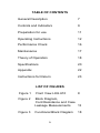
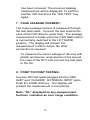
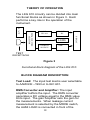
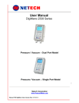
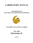
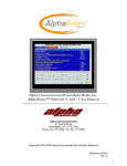
INSTRUCTION MANUAL
LKG 610
Electrical Safety Analyzer
With 10 ECG Connectors
110 Toledo Street • Farmingdale, NY 11735 • USA
Homepage: www.netech.org
Dear User,
We appreciate your purchase of the LKG 610
Electrical Safety Analyzer. Properly used, the
LKG 610 will deliver years of high performance
and accuracy.
This instruction manual has been designed as
a tool to assist you in getting the most from your
LKG 610. In order to properly use and to maintain
this instrument, please read the manual carefully.
Netech is recognized as an innovative designer and
manufacturer of advanced biomedical and industrial
test instruments. We are ISO 9001-2000 registered
and fully committed to a continual improvement
process. Further, we guarantee absolute satisfaction
with our products.
Your business is important to us and we are dedicated
to providing you with the best customer and technical
service possible. Please contact us should you have
any questions or concerns regarding your instrument.
We hope you will consider us again when you have a
requirement for accurate, reliable, affordable test
instruments.
Sincerely,
NETECH CORPORATION
2
Copyright
Copyright © 2003 by Netech Corporation. All rights
reserved. No part of this publication may be reproduced
or transmitted in any form other than for the purchaser’s
personal use without written permission from Netech
Corporation.
Quality Assurance
Netech Corporation is ISO 9001-2000 registered. This
instrument was thoroughly tested and inspected
according to Netech’s ISO 9001-2000 quality standards
(ISO/IEC 17025) and test procedures, and was found to
meet those specifications when it was shipped from the
factory.
Warranty
Netech warranties the LKG 610 against defects in
materials and workmanship for one year from the date of
original purchase. The standard warranty is extended
for a second year if the instrument is returned to
Netech for its recommended yearly re-calibration.
During the warranty period, we will repair or, at our
option, replace at no charge a product that proves to be
defective, provided you return the product shipping
prepaid to Netech Corporation. This warranty does not
apply if the product has been damaged by accident or
misuse, or as the result of service or modification by
other than Netech Corporation, or if its serial number is
defaced or removed.
3
Netech reserves the right to discontinue the LKG 610 at
any time, and change its specifications, price, or design
without notice and without incurring any obligation.
Netech guarantees availability of service parts for 5
years after the manufacture of the unit is discontinued.
The warranty is void if you elect to have the unit serviced
and / or calibrated by someone other than Netech.
The purchaser assumes all liability for any damages or
bodily injury that may result from the use or misuse of
the unit by the purchaser, his employees, agents or
customers.
In no event shall Netech Corporation be liable for
consequential damages
Trademarks
Netech and LKG 610 are trademarks of Netech
Corporation. Any other trademark names used in this
manual are only for editorial purposes and the benefit of
the respective trademark owner, with no intention of
improperly using that trademark.
4
Safety Considerations
General
Before using the LKG 610 read the instruction manual
and become familiar with all of the functions and
controls.
Safety Symbols
WARNING
The “WARNING” sign denotes a hazard. It calls
attention to a procedure, practice or the like, which, if not
correctly performed or adhered to, could result in
personal injury. Do not proceed beyond a “WARNING”
sign until the indicated conditions are fully understood
and met.
CAUTION
The “CAUTION” sign denotes a hazard. It calls attention
to a procedure, practice or the like, which, if not correctly
performed or adhered to, could result in damage to or
destruction of part or all of the instrument. Do not
proceed beyond a “CAUTION” sign until the indicated
conditions are fully understood and met.
!
The symbol to the left is the operator’s manual
symbol. When you see this symbol on the
instrument, refer to the operator’s manual.
5
TABLE OF CONTENTS
General Description
7
Controls and Indicators
9
Preparation for use
11
Operating Instructions
12
Performance Check
16
Maintenance
17
Theory of Operation
18
Specifications
20
Appendix
22
Instructions for Return
23
LIST OF FIGURES
Figure 1
Front View LKG 610
Figure 2
Block Diagram,
Cord Resistance and Case
Leakage Measurements
13
Figure 3
Functional Block Diagram
6
8
18
GENERAL DESCRIPTION
The LKG 610 is a compact Electrical Safety
Analyzer designed to evaluate the electrical
safety of all electrical equipment including medical
devices and physiological Instrumentation.
The LKG 610 measures line voltage, outlet
polarity, device current, earth leakage, chassis
resistance, leads leakage, case leakage, and
performs lead ISO tests and point to point
measurements.
Each measurement is quickly and easily
performed when its function key is pressed. The
function selected and the unit of measure is
indicated by an individual LED. Either the AAMI
ESI -1993 or the IEC 601-1 test load may be
selected.
Resistance measurements are made using the
included model 503 single conductor test lead. A
unique feature of the LKG 610 is its ability to
verify the test readings with calibrated outputs of
200 µ Amps and 1 Ohm.
The comprehensive LKG 610 provides the best
combination of features, performance, and value
in a portable electrical safety analyzer.
7
1
15
2
3
14
4
13
5
12
6
11
7
10
8
9
Figure 1
Front view of the LKG 610
8
CONTROLS AND INDICATORS
1. ECG CONNECTORS: Universal connectors to
connect ECG snaps or various sized posts.
2. DISPLAY: A 3.5 digit LCD presents the result
of the selected test measurement.
3. LOAD SELECTOR SWITCH: Slide switch
selects the AAMI or the IEC 601-1 test load.
4. TEST JACKS: Calibrated outputs are
provided for resistance (1 Ohm) and leakage
current (200 µA).
5. CHASSIS INPUT: Connection for the 503 test
cable.
6. GROUND SWITCH: Momentarily opens the
ground connection to the test receptacle.
7. POLARITY SWITCH: Three-position switch
selects Normal and Reverse polarity of the
test receptacle and turns power Off.
8. NEUTRAL SWITCH: Momentarily opens the
neutral line to the test receptacle.
9. FUSE: 20 Ampere fuse for 110 VAC model,
10 Ampere fuse for 230 VAC model.
10. Serial Port: Optional RS 232 Serial Port.
9
11. ZERO ADJUSTMENT: Recessed adjustment
to zero any test cable resistance variations.
12. TEST RECEPTACLE: 20 Amp hospital grade
receptacle for the Device Under Test.
13. POWER CORD: Power cord and hospital
grade plug.
14. KEY PAD: Twelve push button function keys
to select the test measurement.
15. LEDS: An LED in the corner of each function
key indicates the selected test mode and the
unit of measurement displayed.
10
PREPARATION FOR USE
The LKG 610 includes a test lead, part # 503, for
measuring Cord Resistance and Case Leakage.
Connect the LKG 610 to a 110 VAC outlet (or 220
VAC outlet for the 220 Volt Model).
Before proceeding with any measurement
become familiar with the measurements and the
function selector keys.
During the initial setup the last digit of the LCD
will change gradually due to the time constant of
the RMS to DC converter. The display will
stabilize to zero in a few seconds.
CAUTION
Make sure that the power requirements of the
Device Under Test are within the power ratings of
the LKG 610, 20 amps at 110 volts and 10 amps
at 230 volts.
CAUTION
Do not leave the Device Under Test
continuously turned on and connected to the
LKG 610.
CAUTION
Do not attempt to open the LKG 610. There
are no user serviceable parts inside. Further,
the warranty will be void if the unit is opened
by anybody other than Netech trained
personnel.
11
OPERATING INSTRUCTIONS
1. LINE VOLTAGE MEASUREMENT:
The default measurement setting is line
voltage (LINE VOLT). When the LKG 610 is
plugged into an AC outlet, the LCD will display
the measured line voltage in Volts. If the outlet
polarity is reversed the display will indicate
‘- POL’ and line voltage will not be displayed.
2. DEVICE CURRENT MEASUREMENT:
Plug the Device Under Test (DUT) into the test
receptacle. Set the polarity switch to normal.
Press the “DEVICE CUR” key. Turn the
Device Under Test (DUT) On. The display will
present the Device Current in Amps.
3. EARTH LEAKAGE CURRENT
MEASUREMENT:
Press the “EARTH LKG” key. See Figure 2.
The Earth Leakage (Ground Leakage) Current
is measured through the ground conductor of
the Device Under Test. This is only applicable
to devices with a three-conductor power cord.
The leakage measurement is made internally
when the CHS GND switch is momentarily
pushed to the LIFT GRND position. The
display will present the measurement in
µAmps. No other connection is required.
12
Both Earth and Case Leakage Current
measurements should be made in all power
switch combinations: the Polarity Switch in
Normal, Reverse, and Off; and with the
Neutral Switch Open and Closed.
CAUTION
When switching from Normal to Reverse or
vice versa, make sure to pause the rocker
switch in the OFF position (middle). Power
to the outlet will be OFF in the open neutral
position.
4. CHASSIS RESISTANCE MEASUREMENT:
See Figure 2. Set the Polarity Switch to the
OFF (center) position. Press the key marked
“CHS RES”. Plug the DUT into the test
receptacle. Using the 503 test lead, connect
the chassis of the DUT to the CHASSIS jack
on the LKG 610. The display will present the
Cord Resistance in milliOhms.
DUT Power Cord
503
Test
Lead
to
CHASSIS
Device
Under
Test
Figure 2: Block Diagram of Cord Resistance Measurement and
Case Leakage Measurement.
13
5. LEADS LEAKAGE MEASUREMENT:
Leakage current of ECG leads may be
measured individually or combined. To
measure the leakage press the appropriate
function key LA, RA, RL, LEADS ALL, LL,
or V1-V6. The display will present the selected
test measurement result in µAmps.
6. LEADS ISOLATION TEST:
WARNING:
Since the test method injects potentially
hazardous current levels into the ECG and
related power system, do not conduct tests
in an occupied patient location or while the
patient is connected to a related power
system branch.
CAUTION:
During Isolation leakage measurements the
LKG 610 introduces line voltage into the
patient leads. Even though it is current
limited to 1milliAmp, it is potentially lethal.
Plug the ECG device into the LKG 610.
Connect the ECG leads. Press the “ISO
TEST” key. The isolation leakage will be
presented on the display in µAmps.
After 30 seconds the LED will begin flashing
to indicate that the applied isolation voltage
14
has been removed. The previous leakage
measurement will be displayed. To perform
another ISO test press the “ISO TEST” key
again.
7. CASE LEAKAGE CURRENT:
The Case Leakage Current is measured through
the test lead cable. Connect the test Lead to the
case of the DUT(Device under test). The leakage
measurement is made when the CHS GND switch
is momentarily switched to the LIFT GRND
position. The display will present the
measurement in Micro Amps. No other
connection is required.
To measure the Case Leakage of devices with
plastic enclosures, wrap aluminum foil around
the case of the DUT and connect the test lead
to the foil.
8. POINT TO POINT TESTING:
Use two 503 test leads plugged into the “REF
GND” and “CHASSIS” EXTERNAL INPUT jacks.
Push the CASE LKG key. The display will
present the measurement in microAmps.
Note: “OL” displayed in any measurement
function indicates an over range condition.
15
PERFORMANCE CHECK
The following tests will confirm that the LKG 610
is performing properly.
1. Connect the LKG 610 to a 110 VAC outlet
(220 VAC for the LKG 610-220). The power on
default function is “Line Volt”. The LCD display
will present the line voltage in Volts. If the
outlet polarity is reversed the LCD will indicate
‘- POL’.
2. The Test Lead resistance is offset internally
and adjusted at the factory. The Test Lead
resistance can be checked by connecting the
Test Lead between the receptacle ground and
the case ground (CHASSIS). When the CHS
GND switch is momentarily pressed, the
connection will be open and the display will
read zero.
A test lead other than the 503 may require
adjustment with the zero adjustment
control.
3. Connect the Test Lead to the REF GND jack.
Press the switch “CHS RES”. The display will
read 1000 milliOhms + 5% (1 Ohm).
4. Connect the Test Lead to the TEST POINTS
marked 200 µA. Press the “EARTH LKG” key.
The display will read 200 µA + 2%.
16
MAINTENANCE
The LKG 610 requires minimum maintenance.
Periodically check the inlet plug, outlet receptacle,
and wiring for any damage, wear, cracks, cuts, or
other defects. Also check the case for any
damage or cracks.
In order to ensure accuracy, the LKG 610 should
be checked periodically. A calibrated output is
provided at the TEST JACK for both Case
Leakage and Cord Resistance functions.
When making a resistance measurement with a
Test Cable other than the one supplied with the
LKG 610, the user can zero the leads with the
zero adjustment potentiometer. This will not affect
the internal calibration of the unit.
Annual calibration is recommended. If the LKG
610 is returned to Netech for recalibration before
the first year warranty expires, Netech will provide
a second year warranty. The warranty is void if
the LKG 610 is serviced by anyone other than
Netech or if the warranty seal is broken.
17
THEORY OF OPERATION
The LKG 610 circuitry can be divided into main
functional blocks as shown in Figure 3. Each
performs a key role in the operation of the
instrument.
AAMI or
IEC 601
RMS TO
DC
LEDS
CURRENT
SOURCE
DISPLAY
DSP & FUNCTION
SELECTOR
E
C
G
AMP
TEST
RECEPTACLE
Figure 3
Functional block diagram of the LKG 610.
BLOCK DIAGRAM DESCRIPTION
Test Load: The input test load is user selectable
to AAMI ESI –1993 or to IEC 601.
RMS Converter and Amplifier: The input
amplifier buffers the input. The RMS converter
generates a DC voltage equal to the RMS value
at its input. The gain Amplifier sets the gain for
the measurements. When leakage current
measurement is selected by the MODE switch,
the AAMI LOAD is connected in front of the
18
INPUT AMPLIFIER, and the voltage developed
across it from the leakage current is measured.
Current Source and Amplifier: Resistance is
measured by connecting the current source to the
resistance to be measured and measuring the
voltage with the input amplifier.
Test Receptacle: This supplies power to the unit
under test, 110 VAC rated at 15 Amps (220 VAC).
The rocker polarity switch selects NORMAL, OFF
and REVERSE polarity in the test receptacle.
Display: All measurements are presented on a
3-1/2 digit LCD display.
Over range is indicated by showing a 1 in the
most significant digit.
19
SPECIFICATIONS
METER: 3-1/2 Digit LED display.
LEAKAGE CURRENT:
Current measurements are made through the
AAMI/ANSI ES1-1985 or IEC 601-1 test load.
Meter readings correspond to the true RMS value
of the current.
Range:
0 to 1999 microAmps
Accuracy: DC to 1 KHz: 1% FS + 1 LSD
1 Khz to 100 KHz: ± 2.5% FS + 1 LSD
100 KHz to 1 MHz: ± 4% FS + 1 LSD
RESISTANCE:
Range:
0 TO 1999 MilliOhms.
Accuracy: + 1 % Full Scale + 1 LSD
DEVICE CURRENT:
Range:
0 to 19.99 Amps
Accuracy: + 2% Full Scale + 1 LSD
LINE VOLTAGE:
Range:
1 to 300 Volts
Accuracy: + 2% + 1 Volt
TEST RECEPTACLE:
Hospital Grade 110 VAC -20 Amp or 220 VAC 10
Amp.
The rocker polarity switch selects NORMAL, OFF
and REVERSE Polarity to the test receptacle, and
a momentary Neutral switch will open the neutral
line to the test receptacle.
20
POWER REQUIREMENTS:
110 VAC 50-60Hz, 20 Amps (535 Model)
220 VAC, 10 Amps (535-220 Model)
PHYSICAL DIMENSIONS:
Size: 8.0 X 4.5 X 2.0 inches
(20.3 X 11.4 X 5.0 cm)
Weight: 2.5 lbs (1.1 kg)
ENVIRONMENTAL:
Operating range: 59 to 950 F (15 to 350 C)
Storage Temperature: 0 to 1220 F (-18 to 500 C)
Relative Humidity: 90% (max) at Temperatures
STANDARD ACCESSORIES:
Description
User Manual
Test Cable
Soft Carrying Case
Part Number
535-MANUAL
503
535-Case
21
APPENDIX
22
INSTRUCTIONS FOR RETURN
Damaged in Transit:
All shipments are carefully examined by NETECH
and carefully packaged for shipment. They are
insured in the customer’s name with the carrier.
On receipt, if the shipping container appears to
have been damaged during shipment, the
instrument should be thoroughly inspected.
The delivering carrier’s paper should be signed
noting the apparent damage. If the instrument is
damaged beyond use, a new order should be
placed with NETECH while awaiting
reimbursement from the carrier for the damaged
instruments.
Malfunction:
Please follow these steps for the repair or
recalibration of your NETECH instrument:
1. Obtain a Service /Repair Form
from our website at
www.electricalsafetyanalyzers.com
or from
Customer Service Department
Phone: 631-531-0100
Fax: 631-531-0101
Toll Free: 800-547-6557
2. Complete the Service Form indicating the
instrument’s model number, serial number,
shipping, and billing information. Include the
23
purchase order number or credit card information
for the cost of the repair and/or recalibration.
3. Securely package your instrument in a strong
box, surrounded by at least two inches of suitable
shock absorbing material.
4. Include a copy of the purchase order, or
reference your purchase order on your packing
slip.
5. Include the completed Service Form.
6. Ship the instrument to the following address:
NETECH CORPORATION
110 TOLEDO STREET
FARMINGDALE, NY 11735, USA
ATTN: SERVICE DEPT.
Please visit our web site:
www.electricalsafetyanalyzers.com for the latest
product updates and new product releases.
PN: 535-USER-Manual-R2
24