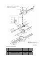
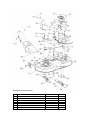
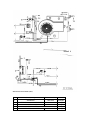
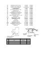
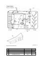
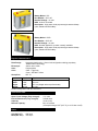
1
ANEXOS
INDICE
Anexo I – Sigmadrive PM Traction Technical Manual
Anexo II – LSM users manual
Anexo III – Zivan NG1 users manual
Anexo IV – Diretiva de Compatibilidade Eletromagnética 2004/108/CE
Anexo V – Diretiva de Baixa Tensão 2006/95/CE
Anexo VI – Planos MTD JE-135
Anexo VII – Optima Batteries
SIGMADRIVE PM TRACTION
TECHNICAL MANUAL
SK79649-01
© PG Drives Technology 2008
All rights reserved.
This manual is furnished under copyright and may only be used in accordance with the terms laid out by PG Drives Technology.
The information in this manual is furnished for informational use only, is subject to change without notice, and should not be
construed as a commitment by PG Drives Technology.
Except as permitted by such terms, no part of this manual may be reproduced, stored in a retrieval system, or transmitted, in any
form or by any means electronic, mechanical, recording, or otherwise - without the prior written permission of PG Drives
Technology. +44 (0) 1425 27144.
PG DRIVES TECHNOLOGY
SIGMADRIVE TECHNICAL MANUAL – PM TRACTION
TABLE OF CONTENTS
About this manual..................................................... 6
Pin 6 – Speed Limit 2 / Inch Reverse............................... 20
Icons
Pin 7 – Speed Limit 3 / Handbrake ................................. 20
...................................................................... 6
Pin 8 – Accelerator / Footbrake...................................... 20
Pin 9 – Accelerator / Footbrake...................................... 20
Chapter 1 – Installation ...............................................................7
Pin 10 – Keyswitch ......................................................... 21
1
Introduction................................................... 9
Pin 11 – Contactor Coil Supply ...................................... 21
2
Guidelines For Working On Electric Vehicles . 9
Pin 12 – Line Contactor ................................................. 21
2.1
Pin 13 – Electric Brake Contactor ................................... 21
Precautions For Working On Electric Vehicles ..........9
Pin 14 – Power Steer Contactor...................................... 21
2.1.1 Uncontrolled Operation .........................................9
Pin 15 – +12V Supply .................................................... 21
2.1.2 High Current Arcs ...................................................9
Pin 16 – +5V Potentiometer Supply................................ 21
2.1.3 Lead Acid Batteries................................................9
2.2
3
6.5
Precautions For Use ...............................................9
Connector ‘B’ – Communications (8-way) ............ 21
Pin 1 – Not Used ............................................................ 21
Frame Dimensions....................................... 10
Pin 2 – Not Used ............................................................ 21
3.1
Small Frame ........................................................ 11
Pin 3 – Flash Programming Mode (+12V)....................... 21
3.2
Medium Frame ................................................... 12
Pin 4 – Flash Programmer I/O......................................... 22
3.3
Large Frame ....................................................... 13
Pin 5 – CAN L ................................................................ 22
Mounting..................................................... 14
Pin 6 – CAN H................................................................ 22
4
4.1
5
Pin 7 – +12V Supply ...................................................... 22
Cable Routing ..................................................... 14
Pin 8 – 0V...................................................................... 22
Wiring Guidance......................................... 15
6.6
Battery and Motor Connections ........................... 16
Pin 1 – Speed Encoder .................................................. 22
5.1.1 Tightening Torque for Battery and Motor
Connections ....................................................... 16
Pin 2 – Remote LED ....................................................... 22
5.2
Battery and Motor Wire Size and Type Selection .... 17
Pin 4 – Thermistor or Steering Potentiometer ................... 22
5.3
Battery and Motor Connection Crimps
and Tooling ......................................................... 17
Pin 5 – +12V Supply ...................................................... 22
5.4
Control Connections............................................ 17
5.5
Control Connection Wiring ................................... 17
5.6
Control Connections Crimps and Tooling ............. 18
7.1
Connections ............................................... 18
7.1.1 Power Cables ...................................................... 23
5.1
6
6.1
Pin 3 – Not Used ............................................................ 22
Pin 6 – 0V...................................................................... 23
7
6.1.4 Emergency Disconnect Switch............................. 18
Emissions............................................................. 23
7.1.3 Controller ............................................................ 23
6.1.1 Power Fuse .......................................................... 18
6.1.3 Discharge Resistor ............................................... 18
Electromagnetic Compatibility (E.M.C.) .......23
7.1.2 Signal Cables ...................................................... 23
Battery Connection.............................................. 18
6.1.2 Line Contactor & Pre-charge Resistor ................... 18
Connector ‘C’ – Motor Feedback (6-way)............. 22
Chapter 2 – Adjustments ......................................................25
1
Adjustments .................................................27
6.2
Motor Connections.............................................. 19
1.1
Acceleration – (Accel) ......................................... 28
6.3
Control Connections............................................ 19
1.2
Deceleration – (Decel)......................................... 28
6.4
Connector ‘A’ – Vehicle Interface (16-way) ........... 19
1.3
Creep Speed – (Creep) ....................................... 28
Pin 1 – Forward Switch ................................................... 19
1.4
Maximum Forward Speed – (SpdMaxF) ................ 28
Pin 2 – Reverse Switch ................................................... 19
1.5
Maximum Reverse Speed – (SpdMaxR) ................ 28
Pin 3 – Footswitch / Belly Button ...................................... 19
1.6
Speed Limit 1 / Inching Speed – (Sp1/Inch)........... 28
Pin 4 – Seat / Tiller .......................................................... 19
1.7
Speed Limit 2 / Inching Time – (Sp2/Time) ............. 28
Pin 5 – Speed Limit 1 / Inch Forward............................... 19
1.8
Speed Limit 3 – (Sp3) ........................................... 29
SK79649-01
3
SIGMADRIVE TECHNICAL MANUAL – PM TRACTION
1.9
PG DRIVES TECHNOLOGY
Direction Regen. Braking – (DBrake)...................... 29
1.7
Power Steering Trigger – (PsF/FR/S)......................... 47
1.10 Neutral Regen. Braking – (NBrake) ........................ 29
1.8
Truck Type Select (Ride/Wlk).................................. 47
1.11 Footbrake Regen. Braking – (FBrake)..................... 29
1.9
Not Used ............................................................. 47
1.12 Direction Braking Ramp – (DBrkRamp) .................. 29
1.10 Display Error Indication – (Of/M/M&W) ................... 48
1.13 Direction Braking End Delay – (DBrkEnd) ................ 29
1.11 Display Status Field – (Of/D/V/K) ............................ 48
1.14 Neutral Braking Ramp – (NBrkRamp) ..................... 30
1.12 Not Used ............................................................. 48
1.15 Neutral Braking End Delay – (NBrkEnd) .................. 30
1.13 Motor Temperature Sensor Type – (MtempTyp) ..... 48
1.16 Regen Speed – (RegSpd) .................................... 30
1.14 Analogue Inputs Set-up – (Accel 8/9) ................... 48
1.17 Maximum Current – (MaxCurr).............................. 30
1.15 Single / Dual Motor Select – (Si/DL/DR).................. 48
1.18 Battery Voltage – (BattV)....................................... 30
1.16 Not Used ............................................................. 49
1.19 Power Steering Delay – (PStrDly) ............................ 30
1.17 CAN Node Number – (CAN node)........................ 49
1.20 Electric Brake Delay – (EBrkDly).............................. 30
1.21 Accelerator 0% Voltage – (AccMin) ..................... 30
1.22 Accelerator 100% Voltage – (AccMax)................. 31
1.23 Footbrake 0% Voltage – (AuxMin)......................... 31
Chapter 5 – Motor Set-up .....................................................51
1
Motor Set-up ................................................53
1.24 Footbrake 100% Voltage – (AuxMax).................... 31
1.1
Motor Temperature Cutback – (TempStrt) ............. 54
1.25 Motor Pot. Min. – (MotMin).................................... 31
1.2
Motor to Vehicle Speed Ratio – (SpdRatio) ........... 54
1.26 Motor Pot. Max. – (MotMax).................................. 31
1.3
Number of Teeth – (SpdTeeth).............................. 54
1.27 Max. Vehicle Speed – (VmaxSpd) ........................ 31
1.4 – 1.29 Not Used ...................................................... 54
1.28 BDI Reset Level – (BDIreset)................................... 31
:: Timed Current Limit Explained :: .................................. 54
1.29 BDI Empty Level – (BDIempty) ............................... 32
1.30 Current Threshold – (CurrTH).................................. 55
1.30 BDI Warning Level – (BDIwarn)............................... 32
1.31 Lower Maximum Current – (ImaxLow) ................... 55
1.31 BDI Cut-out Level – (BDIcut) .................................. 32
1.32 Threshold Timer – (IthTime).................................... 55
1.32 BDI Speed Limit – (BDIspeed)................................ 32
1.33 – 1.38 Offset and Gain Settings.............................. 55
1.33 Dual Motor Cutback – (DMcut)............................. 32
1.34 Dual Motor Reverse – (DMrev) .............................. 32
Chapter 6 – Hand-Held Programmer .........................57
1.35 Dual Motor Speed – (DMspeed) ........................... 32
1
1.36 Standby Delay – (StdByDly) ................................... 33
Chapter 3 – Diagnostics.........................................................35
1
Error Detection ............................................ 37
2
Error Codes ................................................. 38
3
Status .......................................................... 40
4
Further Status Information ............................ 41
5
Test.............................................................. 42
Introduction .................................................59
1.1
2
Interface Switch................................................... 59
Connection .................................................60
2.1
CAN Node Set-up................................................ 60
3
Using the Programmer .................................60
4
Programmer Map ........................................61
4.1
Programming, Diagnostic and Test Options.......... 61
4.1.1 Adjustments ........................................................ 61
4.1.2 Status .................................................................. 61
4.1.3 Controller Set-up.................................................. 61
4.1.4 Motor Set-up ....................................................... 61
Chapter 4 – Controller Set-Up ........................................43
1
4
4.1.5 Test ..................................................................... 61
Controller Set-up ......................................... 45
1.1
Accelerator Characteristic – (Lin/Curv).................. 46
1.2
Not Used ............................................................. 46
1.3
Proportional Braking – (Bpro/Off) ........................... 46
1.4
Anti Roll-back (Restraint) – (Arol/Off) ...................... 47
1.5
Connector A Pin 5 and 6 – (Spd/Inch)................... 47
1.6
Connector A Pin 7 – (Spd3/Hbk)............................ 47
4.1.6 About.................................................................. 62
5
Diagnostics ..................................................62
6
Software Upgrades ......................................62
Chapter 7 – Sigmagauge.......................................................63
1
Introduction .................................................65
SK79649-01
PG DRIVES TECHNOLOGY
1.1
SIGMADRIVE TECHNICAL MANUAL – PM TRACTION
General Information ............................................ 65
1.1.1 Membrane Buttons .............................................. 65
1.1.2 Battery Discharge Indicator .................................. 65
1.1.3 Fault Indication Field............................................ 65
1.1.4 General Indication Field ...................................... 65
1.1.5 Hours Counter ..................................................... 65
1.1.6 Information Field.................................................. 65
2
Connection................................................. 66
3
Mounting..................................................... 66
4
Configuring the Sigmagauge ..................... 67
Chapter 8 – Technical Specifications........................69
1
Electrical ..................................................... 71
1.1
Voltage Specifications ......................................... 71
1.2
Current Specifications.......................................... 71
2
Environmental ............................................. 71
3
Mechanical ................................................ 72
SK79649-01
5
SIGMADRIVE TECHNICAL MANUAL – PM TRACTION
PG DRIVES TECHNOLOGY
About this manual
This manual is divided into 8 chapters.
Chapter 1 – Installation
This chapter deals with the mounting, connection and wiring of the Sigmadrive.
Chapter 2 – Adjustments
This chapter deals with the Sigmadrive’s ‘Adjustments’ parameters.
Chapter 3 – Diagnostics
This chapter provides an overview of the diagnostic capabilities of the Sigmadrive range.
Chapter 4 – Controller Set-up
This chapter deals with the Sigmadrive’s ‘Controller Set-up’ parameters.
Chapter 5 – Motor Set-up
This chapter deals with the Sigmadrive’s ‘Motor Set-up’ parameters.
Chapter 6 – Hand-held Programmer
This chapter provides an overview of the Sigmadrive Hand-held Programmer.
Chapter 7 – Sigmagauge
This chapter provides an overview of the Sigmagauge.
Chapter 8 – Technical Specifications
This chapter provides a summary of the Sigmadrive’s Technical Specifications.
Icons
Throughout this manual, icons are used to draw the reader’s attention.
The icons used are:
Note – A general point for best practice.
Caution – A point of safety which if ignored could result in damage to the control system or the
vehicle.
Warning – A point of safety which if ignored could cause injury to the individual.
PG Drives Technology accepts no liability for any losses of any kind if these points are not followed.
6
SK79649-01
PG DRIVES TECHNOLOGY
PM TRACTION – INSTALLATION
CHAPTER 1 – INSTALLATION
SK79649-01
7
PM TRACTION – INSTALLATION
8
PG DRIVES TECHNOLOGY
SK79649-01
PG DRIVES TECHNOLOGY
1
PM TRACTION – INSTALLATION
Introduction
The Sigmadrive is an advanced digital controller for all popular motor types and is designed for electric vehicle applications such
as Industrial Trucks, Personnel Carriers, Golf Cars, Aerial Work Platforms and Materials Handling Equipment.
Advanced drive algorithms are employed to ensure smooth, accurate, predictable and efficient control of vehicle speed and
torque. Motor reversing and regenerative braking in both directions is achieved via solid-state electronics.
The Sigmadrive has been designed to easily withstand the harsh operating environments that electric vehicles typically endure.
State-of-the-art construction techniques ensure the controller can withstand shock, vibration and extremes of temperature. To
ensure the Sigmadrive installation is as robust as possible, follow the guidelines in this manual.
2
2.1
Guidelines For Working On Electric Vehicles
Precautions For Working On Electric Vehicles
Working on any electrical system can be dangerous. Work on electric vehicles should only be undertaken by skilled or supervised
persons, in a segregated location that eliminates the risk of injury to other persons. Before performing any kind of work on electric
vehicles, ensure that the following basic safety advice is followed.
2.1.1
Uncontrolled Operation
Fault conditions or programming changes may cause the motor to run out of control. Disconnect the motor or raise the drive
wheels above the ground. If lifting the vehicle, use the correct jacking procedure as recommended by the vehicle manufacturer
to lift the vehicle’s drive wheels clear of the ground. Once lifted, fit axle stands to safely support the vehicle and remove the jack.
Ensure that all such lifting equipment is in serviceable condition and suitable for the vehicle in question.
2.1.2
High Current Arcs
Batteries contain very high levels of energy and can be extremely dangerous if mishandled or abused. Always disconnect the
batteries before working on the vehicle’s electrical system and the motor controller wiring. Remove all jewellery from wrist and
fingers and use properly insulated tools to prevent shorts. Wear safety glasses at all times.
2.1.3
Lead Acid Batteries
Charging or discharging lead acid batteries generates hydrogen gas, which can build up in and around the battery area. Ensure
charging is performed in a ventilated area. Follow the battery manufacturer’s safety recommendations. Wear safety glasses at all
times.
2.2
Precautions For Use
Do not drive the vehicle:
SK79649-01
•
Beyond restrictions indicated in your vehicle user manual, for example inclines, curb heights etc.
•
In places or on surfaces where a loss of wheel grip could be hazardous, for example on wet grassy slopes.
•
If you know that the controller or other crucial components require repair.
9
PM TRACTION – INSTALLATION
PG DRIVES TECHNOLOGY
Although the controller is designed to be extremely reliable and each unit is rigorously tested
during manufacture, the possibility of system malfunction always exists (however small the
probability). Under some conditions of system malfunction the controller must (for safety
reasons), stop the vehicle instantaneously. If there is any possibility of the user falling out of the
vehicle as a result of a sudden braking action, it is imperative that a restraining device such as a
seat belt is supplied with the vehicle and that it is in use at all times when the vehicle is in
motion. PGDT accept no liability for losses of any kind arising from the unexpected stopping of
the vehicle, or arising from the improper use of the vehicle or controller.
Do not operate the controller if the vehicle behaves erratically, or shows abnormal signs of
heating, sparks or smoke. Turn the controller off at once and consult your service agent. PGDT
accepts no liability for losses of any kind arising from failure to comply with this condition.
Electronic equipment can be affected by Electro Magnetic Interference (EMI). Such interference
may be generated by radio stations, TV stations, other radio transmitters and cellular phones. If
the vehicle exhibits erratic behavior due to EMI, turn the controller off immediately and consult
your service agent. PGDT accepts no liability for losses of any kind arising from failure to comply
with this condition.
It is the responsibility of the vehicle manufacturer to ensure that the vehicle complies with
appropriate National and International EMC legislation. PGDT accepts no liability for losses of
any kind arising from failure to comply with this condition.
The vehicle user must comply with all vehicle safety warnings. PGDT accepts no liability for
losses of any kind arising from failure to comply with this condition.
3
Frame Dimensions
The Sigmadrive is constructed in three frame sizes – small, medium and large. This can be identified from the last character of
the product code. For example, PMT425SS is a Small frame size.
10
SK79649-01
PG DRIVES TECHNOLOGY
3.1
PM TRACTION – INSTALLATION
Small Frame
SK79649-01
11
PM TRACTION – INSTALLATION
3.2
12
PG DRIVES TECHNOLOGY
Medium Frame
SK79649-01
PG DRIVES TECHNOLOGY
3.3
PM TRACTION – INSTALLATION
Large Frame
SK79649-01
13
PM TRACTION – INSTALLATION
4
PG DRIVES TECHNOLOGY
Mounting
Careful consideration should be given to the location chosen to mount the controller. Although the Sigmadrive benefits from
excellent environmental protection, it is good engineering practice for the selected position to be clean and dry, to minimize
shock, vibration, temperature changes and exposure to water & contaminants.
If vertical orientation mounting is not possible, then a cover should be used to shield the controller. Cables must be routed to
prevent liquids flowing into the connections. The mounting position should also allow access to all connections and allow the
connection and removal of a programming device.
Secure the controller to the vehicle via the four clearance holes provided. Ideally, a flat clean metal surface will provide
maximum heat dissipation and ensure full rated power output. Failure to use all four mounting points may result in a loss in
performance. Any airflow around the controller will further enhance the thermal performance. If desired, the controller’s thermal
performance may be further improved by applying a silicone-free thermal compound between the baseplate and the machine
chassis.
The Small Frame controller has M6 (1/4") clearance holes.
The Medium and Large Frame controllers have M8 (5/16") clearance holes.
Under strenuous driving conditions, it is possible for metal sections of the controller’s case to
exceed 41°C (106 °F). Under such conditions, the machine manufacturer should ensure that either
the user cannot touch these surfaces, or that the user is warned not to touch these surfaces.
While 41°C (106 °F) is very close to normal body temperature, prolonged contact with surfaces
above 41°C (106 °F) can result in burns to the skin. PGDT accepts no liability for losses of any
kind arising from failure to comply with this condition.
4.1
Cable Routing
The cables to the controller must be routed and secured in such a way as to prevent damage, for example by chafing or
crushing, or exposure to solvents or other chemicals that may degrade the insulation. It is suggested that the cables are
mounted so that they loop up to the controller, therefore minimizing the flow of moisture into the connectors. Route wiring to
keep lengths as short as possible, especially the high current motor and battery cabling.
14
SK79649-01
PG DRIVES TECHNOLOGY
5
PM TRACTION – INSTALLATION
Wiring Guidance
SK79649-01
15
PM TRACTION – INSTALLATION
5.1
PG DRIVES TECHNOLOGY
Battery and Motor Connections
Five copper terminals with threaded holes are provided for the high current connections. These are identified as B+, B-, M1, M2
and M3. The controller is provided with suitable screws, spring washers and flat washers for fastening the battery and motor
cables. PGDT recommends the arrangement of screw, spring washer and flat washer as shown below for the correct termination
of the high power connectors.
The small frame size has M6 threaded holes, while the medium and large frame sizes have M8 threaded holes.
If alternate screws or bolts are used, it is essential that the thread insertion depth is less than
14mm. Damage to the controller may occur if this depth is exceeded.
After securely fitting the high current cables, do not put undue upward pressure on them by
twisting or pulling – this may result in damage to the terminal pillars. If the cable position needs
to be readjusted, loosen the screw and washer arrangement first.
5.1.1
Tightening Torque for Battery and Motor Connections
The medium and large frame sizes use M8 screws and these should be tightened to 11Nm.
The small frame size uses M6 screws and these should be tightened to 9Nm.
16
SK79649-01
PG DRIVES TECHNOLOGY
5.2
PM TRACTION – INSTALLATION
Battery and Motor Wire Size and Type Selection
The wiring arrangement used on a particular vehicle can greatly affect the current carrying capacities of individual wires.
Ambient temperature, grouping and wire length can all significantly de-rate cable performance and other factors such as
vehicle duty cycles and airflow should also be taken into consideration when selecting vehicle wiring.
PGDT recommends the use of BS6231 (UL 1015, 1028, 1283 or 1284 dependent on wire gauge), Tri-rated wire due to its superior
flexibility and 90/105°C temperature rating. The table below shows the minimum recommended wire sizes for the Motor and
Battery connections on the Sigmadrive controllers.
Frame Size
Small
Medium
Large
Motor
16 mm2
35 mm2
70 mm2
Battery
16 mm2
35 mm2
70 mm2
It is the responsibility of the vehicle manufacturer to ensure that the vehicle’s wiring arrangement
is suitable for the intended application, and complies with all necessary standards that are
dictated by the relevant approvals of regulatory organizations. PGDT accepts no liability for
losses of any kind arising from an inappropriate wiring arrangement.
5.3
Battery and Motor Connection Crimps and Tooling
Good quality crimping is essential in ensuring the long-term reliability of the vehicle’s electrical system. Poor quality crimps may
initially appear satisfactory, but can deteriorate over time, ultimately causing the vehicle to break down. For the battery and
motor connections, the use of AMP® AMPower III or Solistrand copper tube leg terminals is recommended. It is absolutely vital
that the selected crimp terminal is designed to be used with the wire size and type being used.
It is also vital that for the selected crimp terminal the correct tooling is used for its installation onto the wire, and that the
procedure for doing so is followed correctly. Contact the crimp terminal manufacturer to ensure that the tooling employed is
suitable for use with the chosen combination of wire and crimp terminal.
If insulated crimps are used, ensure the insulation is firmly pushed into place. If uninsulated crimps are used, it is recommended
that heatshrink or similar sleeving is used to insulate the barrel of the crimp terminal.
Ensure that only fully trained and skilled operators perform the crimping procedure and that the
instructions provided by the crimp terminal manufacturer are followed. PGDT accepts no liability
for losses of any kind if the recommendations made in this section are not followed.
5.4
Control Connections
The low current control connections on the Sigmadrive are via Molex® SMD Micro Fit 3.0 Series connectors. These connectors are
labeled as A, B and C on the cover of the controller and provide the following functions.
5.5
A
16-way Vehicle Interface Connector
B
8-way Communications Connector
C
6-way Motor Feedback Connector
Control Connection Wiring
Use 0.5mm2/18AWG wire gauge for all control connections. It is also recommended that Tri-rated wire with a 105ºC insulation
rating is used.
SK79649-01
17
PM TRACTION – INSTALLATION
5.6
PG DRIVES TECHNOLOGY
Control Connections Crimps and Tooling
The following table shows the Molex part numbers for the mating crimps, housings, crimp tool and extraction tool.
Alternatively, the mating connectors can be purchased directly from PGDT using the connector kit part numbers shown.
Connector
A – 16-way
B – 8-way
C – 6-way
PGDT Connector
Kit Part No.
D51066
D51068
D51067
Molex Housing
Part No.
43025-1600
43025-0800
43025-0600
Molex Crimp
Part No.
43030-0007
43030-0007
43030-0007
Molex Crimp
Tool Part No.
Molex Extraction
Tool Part No.
69008-0982
11-03-0043
PGDT recommends that only genuine Molex parts should be used. Inferior quality crimps or
incorrect tooling can seriously reduce the reliability and longevity of the controller or vehicle.
PGDT accepts no liability for losses of any kind if non-recommended parts are used.
6
Connections
6.1
Battery Connection
Connect the positive supply to the B+ terminal and the negative supply to the B- terminal.
6.1.1
Power Fuse
A suitable fuse must be fitted to the battery positive supply. This fuse should be fitted as closely as possible to the battery’s positive
terminal.
6.1.2
Line Contactor & Pre-charge Resistor
A suitable line contactor must be connected to the battery positive supply. This should be fitted with a 5W 10kΩ pre-charge
resistor connected in parallel across the contacts. The coil of the line contactor can be controlled by the Sigmadrive, via pin 12
of Connector A.
6.1.3
Discharge Resistor
Units manufactured before October 2008 require an external discharge resistor. The resistor should be fitted between the
Sigmadrive’s B+ and B- terminals. The correct value for each controller model is shown below.
24V only Sigmadrive – 10kΩ 1/4W
24V – 48V Sigmadrive – 22kΩ 1/4W
72V – 80V Sigmadrive – 47kΩ 1/4W
6.1.4
Emergency Disconnect Switch
For certain vehicle types, safety legislation requires that an emergency battery disconnect switch or switches should be fitted in
the battery positive supply, in order to allow complete isolation of the vehicle’s electrical system from the battery. The location of
this switch or switches should be as stipulated in the appropriate legislative documentation.
It is the responsibility of the vehicle manufacturer to ensure appropriate fuses, line contactors
and emergency disconnect switches are used and that these devices are appropriately located.
PGDT accepts no liability for losses of any kind if inappropriate devices or arrangements are
used.
18
SK79649-01
PG DRIVES TECHNOLOGY
6.2
PM TRACTION – INSTALLATION
Motor Connections
The motor should be connected between the M1 terminal and the M3 terminal of the controller. The M2 terminal remains
unconnected. If, when a forward command is applied, the vehicle drives in reverse, swap the motor wires.
6.3
Control Connections
The control connections are via three connectors with pin-outs as follows.
Connector A: Vehicle Interface
Connector B: Communications to display module and/or programmer
Connector C: Motor Feedback
Details of the functions of each of the pins for these connectors are shown in the following section.
6.4
Connector ‘A’ – Vehicle Interface (16-way)
Pin 1 – Forward Switch
This switch must be closed in conjunction with the Accelerator to give a forward drive signal.
Pin 2 – Reverse Switch
This switch must be closed in conjunction with the Accelerator to give a reverse drive signal.
Pin 3 – Footswitch / Belly Button
The function of this input is set by the programmable parameter, 3.8 Truck Type Select.
If set to Ride, then the vehicle’s Footswitch should be connected to this pin, and must be closed to allow drive.
If set to Wlk, then the vehicle’s Belly Button switch should be connected to this pin. When the Belly Button switch is closed,
the vehicle will drive in the opposite direction for 1.5s.
Pin 4 – Seat / Tiller
The function of this input is to provide a general safety interlock. This could be a Seat switch on a ride-on vehicle, a Tiller
switch on a “walkie” vehicle or a general deadman’s trigger on other vehicle types. The switch must be closed to allow
drive.
Pin 5 – Speed Limit 1 / Inch Forward
The function of this input is set by the programmable parameter, 3.5 Connector A Pin 5 and 6.
If set to Spd, then this input can be used to limit the speed of the vehicle to a value set by the programmable parameter,
1.6 Speed Limit 1. The speed limit will occur when the switch is open.
If set to Inch, then this input is used to “inch” the vehicle in the forward direction. Inching will occur when the switch is
closed. The exact functionality of inching is set by the programmable parameters, 1.6 Inching Speed and 1.7 Inching
Time.
SK79649-01
19
PM TRACTION – INSTALLATION
PG DRIVES TECHNOLOGY
Pin 6 – Speed Limit 2 / Inch Reverse
The function of this input is set by the programmable parameter, 3.5 Connector A Pin 5 and 6.
If set to Spd, then this input can be used to limit the speed of the vehicle to a value set by the programmable parameter,
1.7 Speed Limit 2. The speed limit will occur when the switch is open.
If set to Inch, then this input is used to “inch” the vehicle in the reverse direction. Inching will occur when the switch is
closed. The exact functionality of inching is set by the programmable parameters, 1.6 Inching Speed and 1.7 Inching
Time.
Pin 7 – Speed Limit 3 / Handbrake
This input is primarily intended to be used with a handbrake switch, however, its function can be set by the programmable
parameter, 3.6 Connector A Pin 7.
If set to Spd3, then this input can be used to limit the speed of the vehicle to a value set by the programmable
parameter, 1.8 Speed Limit 3. The speed limit will occur when the switch is open.
If set to Hbk, then this input should be connected to the vehicle’s handbrake switch. When the switch is closed, i.e. the
handbrake is on, the vehicle’s speed will be as set by the programmable parameter, 1.8 Speed Limit 3.
Pin 8 – Accelerator / Footbrake
This is an analogue input that will accept a 2-wire 5kΩ potentiometer or a 0V to 5V voltage signal.
The function of this input is set by the programmable parameter, 3.14 Analogue Inputs Set-up.
If set to 0, then this input should be connected to the vehicle’s Accelerator device.
If set to 1, then this input should be connected to the vehicle’s Footbrake device.
When set to 0, the active range of the accelerator input is defined by the programmable parameters, 1.21 Accelerator
0% Voltage and 1.22 Accelerator 100% Voltage. The former parameter sets the voltage that relates to zero drive demand
from the Accelerator, while the latter parameter sets the voltage that relates to 100% drive demand from the Accelerator.
When set to 1, the active range of the footbrake input is defined by the programmable parameters, 1.23 Footbrake 0%
Voltage and 1.24 Footbrake 100% Voltage. The former parameter sets the voltage that relates to zero braking demand
from the Footbrake, while the latter parameter sets the voltage that relates to 100% braking demand from the Footbrake.
If a Footbrake switch is used on the brake pedal instead of an analogue device, the switch should connect this input to
the voltage corresponding to the value of parameter, 1.24 Footbrake 100% Voltage, in order to effect full braking.
Pin 9 – Accelerator / Footbrake
This is an analogue input that will accept a 3-wire 5kΩ potentiometer or a 0V to 5V voltage signal.
The function of this input is set by the programmable parameter, 3.14 Analogue Inputs Set-up.
If set to 0, then this input should be connected to the vehicle’s Footbrake device.
If set to 1, then this input should be connected to the vehicle’s Accelerator device.
When set to 0, the active range of the footbrake input is defined by the programmable parameters, 1.23 Footbrake 0%
Voltage and 1.24 Footbrake 100% Voltage. The former parameter sets the voltage that relates to zero braking demand
from the Footbrake, while the latter parameter sets the voltage that relates to 100% braking demand from the Footbrake.
If a Footbrake switch is used on the brake pedal instead of an analogue device, the switch should connect this input to
the voltage corresponding to the value of parameter, 1.24 Footbrake 100% Voltage, in order to effect full braking.
When set to 1, the active range of the accelerator input is defined by the programmable parameters, 1.21 Accelerator
0% Voltage and 1.22 Accelerator 100% Voltage. The former parameter sets the voltage that relates to zero drive demand
from the Accelerator, while the latter parameter sets the voltage that relates to 100% drive demand from the Accelerator.
20
SK79649-01
PG DRIVES TECHNOLOGY
PM TRACTION – INSTALLATION
Pin 10 – Keyswitch
This input should be connected to the switched side of the keyswitch. The other side of the keyswitch should be
connected to the battery positive supply.
A fuse of sufficient value to supply all contactor coil currents should be connected between the battery positive supply
and the keyswitch. The position of the fuse should be as close as possible to the tap-off point for the keyswitch supply.
Pin 11 – Contactor Coil Supply
This output is the positive supply to the vehicle’s contactors. The voltage level of this supply corresponds to the vehicle’s
battery voltage. The maximum supply current from this pin is 3A.
Pin 12 – Line Contactor
This pin should be connected to the negative side of the Line Contactor coil. The Sigmadrive will control the Line
Contactor as required. The maximum rating for this connection is 3A and it is fully protected for use with inductive loads.
Pin 13 – Electric Brake Contactor
This pin should be connected to the negative side of the Braking Contactor coil. The Sigmadrive will control the Braking
Contactor as required. The maximum rating for this connection is 3A and it is fully protected for use with inductive loads.
Pin 14 – Power Steer Contactor
This pin should be connected to the negative side of the Power Steer Contactor coil. The Sigmadrive will control the Power
Steer Contactor as required. The maximum rating for this connection is 3A and it is fully protected for use with inductive
loads.
An external contactor driver is required when using pin 14 on small frame Sigmadrive controllers.
Please contact PGDT for further information if a Power Steer Contactor is required for this size
of Sigmadrive.
Pin 15 – +12V Supply
A 12V supply. The maximum supply current is 20mA from this pin.
Pin 16 – +5V Potentiometer Supply
A supply for the 5kΩ Accelerator or Footbrake potentiometer connected to pin 9 and the remote LED connected to pin 2
of Connector C (if fitted).
6.5
Connector ‘B’ – Communications (8-way)
Pin 1 – Not Used
Not used.
Pin 2 – Not Used
Not used.
Pin 3 – Flash Programming Mode (+12V)
For use with the Flash Programmer.
SK79649-01
21
PM TRACTION – INSTALLATION
PG DRIVES TECHNOLOGY
Pin 4 – Flash Programmer I/O
For use with the Flash Programmer.
Pin 5 – CAN L
CAN Low communications line to the Programming Device, Display or other Controller(s).
Pin 6 – CAN H
CAN High communications line to the Programming Device, Display or other Controller(s).
Pin 7 – +12V Supply
A 12V supply. The maximum supply current is 20mA from this pin.
Pin 8 – 0V
A 0V supply for the Programming Device or Display.
6.6
Connector ‘C’ – Motor Feedback (6-way)
Pin 1 – Speed Encoder
Connect to the speed signal of the motor encoder.
Pin 2 – Remote LED
This output can be connected, via pin 16 of Connector A, to an external fault indication LED.
If an error is detected during operation, the external fault indicator will flash synchronously with the Sigmadrive’s integral red
diagnostic LED.
Pin 3 – Not Used
Not used.
Pin 4 – Thermistor or Steering Potentiometer
The function of this input is set by the programmable parameter, 3.15 Single / Dual Motor Select, in the Controller Set-up
menu.
If set to 0 (Motor Temperature), then this input can be connected to an external thermistor, typically on the motor, which
can be used to reduce controller current output with respect to temperature. The type of thermistor is set by the
parameter, 3.13 Motor Temperature Sensor Type. Once the correct sensor type has been set, the parameter, 4.1 Motor
Temperature Cutback, can then be used to set the temperature at which current foldback will begin.
If set to either 1 (Dual Motor Left) or 2 (Dual Motor Right), then this input can be connected to a 3-wire 5kΩ potentiometer
that measures the steering angle of the vehicle. The potentiometer should be connected to a 5V supply – a convenient
connection point can be found on pin 16 of Connector A.
The active range of the input when used by a steering potentiometer is defined by the parameters, 1.25 Motor Pot. Min.
and 1.26 Motor Pot. Max. 1.25 Motor Pot. Min. sets the voltage that relates to the minimum (full left hand lock) steering
angle, while 1.26 Motor Pot. Max. sets the voltage that relates to the maximum (full right hand lock) steering angle.
Pin 5 – +12V Supply
A 12V supply with a maximum current of 20mA. This output can be used for the motor encoder supply.
22
SK79649-01
PG DRIVES TECHNOLOGY
PM TRACTION – INSTALLATION
Pin 6 – 0V
A 0V connection point for the Speed Encoder and Steering Potentiometer.
Avoid routing the 6-way motor feedback cables close to the motor power cables - they must not
be tie-wrapped together. If screened cable is used, contact PGDT for details on how to connect
this at the motor and controller ends. This is critical to help avoid any noise or incorrect speed
measurement issues.
7
Electromagnetic Compatibility (E.M.C.)
You should consider EMC and perform relevant tests as early as possible in the design phase.
7.1
Emissions
Any high-speed switch is capable of generating harmonics at frequencies that are many multiples of its basic operating
frequency. It is the objective of a good installation to contain or absorb the resultant emissions. All wiring is capable of acting as
a receiving or transmitting antenna. Wiring should be arranged to take maximum advantage of the structural metal work inherent
in most vehicles. Vehicle metalwork should be electrically linked with conductive braids.
7.1.1
Power Cables
All cables should be routed within the vehicle framework and kept as low in the structure as is practical; a cable run within a main
chassis member is better screened from the environment than one routed through or adjacent to an overhead guard. Power
cables should be kept short to minimize emitting and receiving surfaces. Shielding by the structure may not always be sufficient;
cables run through metal shrouds may be required to contain emissions.
Parallel runs of cables in common circuits can serve to cancel emissions, e.g. the battery positive and negative cables following
similar paths.
Tie all cables into a fixed layout and do not deviate from the approved layout in production vehicles. A re-routed battery cable
could negate any approvals obtained.
7.1.2
Signal Cables
All wiring harnesses should be kept short. Wiring should be routed close to the vehicle metalwork. All signal wires should be kept
clear of power cables or made from screened cable. This is particularly important if the control wiring carries analogue
information, e.g. Accelerator wiring. Tie all wiring securely and ensure it always follows the same layout.
7.1.3
Controller
Thermal and EMC (emissive) requirements tend to work in opposition. Additional insulation between the controller assembly and
the vehicle framework reduces capacitive coupling and hence emissions but tends to reduce the thermal performance. A
working balance needs to be established by experiment. The complete installation should be documented in detail and faithfully
reproduced on all production vehicles. When making changes, consider their effect on compliance, ahead of other factors
such as cost reduction.
SK79649-01
23
PM TRACTION – INSTALLATION
24
PG DRIVES TECHNOLOGY
SK79649-01
PG DRIVES TECHNOLOGY
PM TRACTION – ADJUSTMENTS
CHAPTER 2 – ADJUSTMENTS
SK79649-01
25
PM TRACTION – ADJUSTMENTS
26
PG DRIVES TECHNOLOGY
SK79649-01
PG DRIVES TECHNOLOGY
1
PM TRACTION – ADJUSTMENTS
Adjustments
The Sigmadrive Programmer ‘Adjustments’ menu (1. Adjustments), contains the parameters shown in the table below. Each
parameter has a unique reference number, 1.x, as shown in the left-hand column. The parameter name as it appears on the
Programmer screen and parameter range are also shown.
Ref.
1.1
1.2
1.3
1.4
1.5
1.6
1.7
1.8
1.9
1.10
1.11
1.12
1.13
1.14
1.15
1.16
1.17
1.18
1.19
1.20
1.21
1.22
1.23
1.24
1.25
1.26
1.27
1.28
1.29
1.30
1.31
1.32
1.33
1.34
1.35
1.36
SK79649-01
Parameter
Acceleration
Deceleration
Creep Speed
Maximum Forward Speed
Maximum Reverse Speed
Speed Limit 1
Inching Speed
Speed Limit 2
Inching Time
Speed Limit 3
Direction Regen. Braking
Neutral Regen. Braking
Footbrake Regen Braking
Direction Braking Ramp
Direction Braking End Delay
Neutral Braking Ramp
Neutral Braking End Delay
Regen Speed
Maximum Current
Battery Voltage
Power Steering Delay
Electric Brake Delay
Accelerator 0% Voltage
Accelerator 100% Voltage
Footbrake 0% Voltage
Footbrake 100% Voltage
Motor Pot. Min.
Motor Pot. Max.
Max. Vehicle Speed
BDI Reset Level
BDI Empty Level
BDI Warning Level
BDI Cut-out Level
BDI Speed Limit
Dual Motor Cutback
Dual Motor Reverse
Dual Motor Speed
Standby Delay
Programmer Text
Accel
Decel
Creep
SpdMaxF
SpdMaxR
Sp1
Inch
Sp2
Time
Sp3
DBrake
NBrake
FBrake
DBrkRamp
DBrkEnd
NBrkRamp
NBrkEnd
RegSpd
MaxCurr
BattV
PStrDly
EBrkDly
AccMin
AccMax
AuxMin
AuxMax
MotMin
MotMax
VmaxSpd
BDIreset
BDIempty
BDIwarn
BDIcut
BDIspeed
DMcut
DMrev
DMspeed
StdByDly
Range
0.1s – 10.0s
0.1s – 10.0s
0% – 25%
0% – 100%
0% – 100%
0% – 100%
0% – 25%
0% – 100%
0.1s – 10.0s
0% – 100%
50A – Unit max.
50A – Unit max.
50A – Unit max.
0.1s – 10.0s
0.1s – 10.0s
0.1s – 10.0s
0.1s – 10.0s
0% – 100%
10A – Unit max.
24V – Unit max.
0s – 50s
0s – 50s
0V – 5V
0V – 5V
0V – 5V
0V – 5V
0V – 5V
0V – 5V
0 kph – 100 kph
18V – 125% Bat. V
12V – 125% Bat. V
0% – 99%
0% – 99%
0% – 100%
0% – 100%
0% – 100%
0% – 100%
0 min (off) – 10 min
27
PM TRACTION – ADJUSTMENTS
1.1
PG DRIVES TECHNOLOGY
Acceleration – (Accel)
This sets the time taken to accelerate from zero speed to maximum speed.
The maximum speed demand is set by 1.4 Maximum Forward Speed and 1.5 Maximum Reverse Speed.
Increasing the value results in a slower vehicle acceleration, while decreasing the value results in a faster vehicle acceleration.
The adjustable range is 0.1s to 10.0s in 0.1s steps.
1.2
Deceleration – (Decel)
This sets the time taken to decelerate from maximum speed to zero speed.
Increasing the value results in a slower vehicle deceleration, while decreasing the value results in a faster vehicle deceleration.
The adjustable range is 0.1s to 10.0s in 0.1s steps.
1.3
Creep Speed – (Creep)
This effectively sets the initial speed that the vehicle will adopt on entering drive.
Increasing the value will help minimise any delay from selecting drive to creeping the vehicle.
The adjustable range is 0% to 25% in 1% steps.
1.4
Maximum Forward Speed – (SpdMaxF)
This sets the maximum forward speed of the vehicle.
The adjustable range is 0% to 100% in 1% steps.
1.5
Maximum Reverse Speed – (SpdMaxR)
This sets the maximum reverse speed of the vehicle.
The adjustable range is 0% to 100% in 1% steps.
1.6
Speed Limit 1 / Inching Speed – (Sp1/Inch)
The function of this parameter is dependent on the setting of, 3.5 Connector A Pin 5 and 6, in the Controller Set-up menu. That
parameter sets whether pins 5 and 6 are used as speed limiting inputs or as inching control inputs.
If set to 0, then Speed Limit 1 sets the maximum speed of the vehicle when a switch connected to pin 5 on Connector A is open.
The speed limit is not applied when the switch is closed or a lower speed limit is in operation.
The adjustable range is between 0% and 100% in 1% steps.
If set to 1, then Inching Speed sets the speed of the vehicle (in both directions), that will be active when a switch connected to
pin 5 or pin 6 of Connector A is closed. The vehicle will not inch when the switch is open.
The adjustable range is 0% to 25% in 1% steps.
1.7
Speed Limit 2 / Inching Time – (Sp2/Time)
The function of this parameter is dependent on the setting of, 3.5 Connector A Pin 5 and 6, in the Controller Set-up menu. That
parameter sets whether pins 5 and 6 are used as speed limiting inputs or as inching control inputs.
If set to 0, then Speed Limit 2 sets the maximum speed of the vehicle when a switch connected to pin 6 on Connector A is open.
The speed limit is not applied when the switch is closed or a lower speed limit is in operation.
The adjustable range is between 0% and 100% in 1% steps.
If set to 1, then Inching Time sets the period (in both directions), the vehicle will be moving for, when a switch connected to pin 5
or pin 6 of Connector A is closed. The vehicle will not inch when the switch is open.
28
SK79649-01
PG DRIVES TECHNOLOGY
PM TRACTION – ADJUSTMENTS
The adjustable range is 0.1s to 10s in 0.1s steps.
For ease of adjustment, this parameter should be set to 0% before programming 3.5 Connector A
Pin 5 and 6 to ‘Inching’.
1.8
Speed Limit 3 – (Sp3)
The function of this parameter is dependent on the setting of, 3.6 Connector A Pin 7, in the Controller Set-up menu.
If set to 0, then Speed Limit 3 sets the maximum speed of the vehicle when a switch connected to Pin 7 on Connector A is open.
The speed limit is not applied when the switch is closed or a lower speed limit is in operation.
If set to 1, then Speed Limit 3 sets the maximum speed of the vehicle when a switch connected to Pin 7 on Connector A is
closed. The speed limit is not applied when the switch is open or a lower speed limit is in operation. Please note, that even if this
parameter is set to 0%, the controller will continue to pulse whilst the Foot Switch is closed. This is designed to avoid rollback on
gradients.
The adjustable range is 0% to 100% in 1% steps.
1.9
Direction Regen. Braking – (DBrake)
This sets the maximum level of current used for braking, upon a direction change.
The adjustable range is 50A to the maximum controller current in 10A steps.
1.10
Neutral Regen. Braking – (NBrake)
This sets the maximum level of current used for braking, when the vehicle is in neutral, i.e. no drive signal in either direction.
The adjustable range is 50A to the maximum controller current in 10A steps.
1.11
Footbrake Regen. Braking – (FBrake)
This sets the maximum level of current used for braking, when the brake pedal is fully operated, i.e. the voltage from the
footbrake potentiometer is equal to the setting of the parameter, 1.24 Footbrake 100% Voltage.
The adjustable range is 50A, to the maximum controller current in 10A steps.
The Footbrake Regen. Current is proportional to the brake pedal from 0A to this value.
1.12
Direction Braking Ramp – (DBrkRamp)
This sets the time taken to ramp down from maximum speed in the current direction to zero, upon a change of direction. After
passing through zero speed, the normal acceleration time as described in 1.1 Acceleration, applies. Increasing the value gives a
smoother but longer transition to zero speed.
The regenerative current during braking is limited by 1.9 Direction Regen. Braking. When this level is reached, the direction braking
ramp time is prolonged until the regenerative current falls below the maximum current level. At this point, the ramp time takes
over again.
The adjustable range is 0.1s to 10s in 0.1s steps.
1.13
Direction Braking End Delay – (DBrkEnd)
This setting allows a time to hold the vehicle at zero speed when 1.12 Direction Braking Ramp time has passed.
The value set by this parameter is ignored during Belly Button and Inching operation.
The adjustable range is 0.1s to 10.0s in 0.1s steps.
SK79649-01
29
PM TRACTION – ADJUSTMENTS
1.14
PG DRIVES TECHNOLOGY
Neutral Braking Ramp – (NBrkRamp)
This sets the time taken to ramp down from maximum speed to zero, when the vehicle enters neutral, i.e. no drive signal in either
direction. Increasing the value gives a smoother but longer transition to zero speed.
The regenerative current during braking is limited by 1.10 Neutral Regen. Braking. When this level is reached, the neutral braking
ramp time is prolonged until the regenerative current falls below the maximum current level. At this point, the ramp time takes
over again.
The adjustable range is 0.1s to 10s in 0.1s steps.
1.15
Neutral Braking End Delay – (NBrkEnd)
This setting is normally associated with a Walkie-type vehicle fitted with an electromechanical brake connected to pin 13 on
Connector A. This setting allows a time to hold the vehicle at zero speed when the 1.14 Neutral Braking Ramp time has passed. It
is usually used in conjunction with the parameter 1.20 Electric Brake Delay to operate the electromechanical brake.
The value set by this parameter is ignored during Belly Button and Inching operation.
The adjustable range is 0.1s to 10.0s in 0.1s steps.
1.16
Regen Speed – (RegSpd)
This sets the minimum speed a vehicle has to reach in order for the braking end delay functionality to operate.
The adjustable range is 0% to 100% in steps of 1%.
1.17
Maximum Current – (MaxCurr)
This sets the maximum current limit during driving.
The adjustable range is 10A to the maximum rating of the controller in 10A steps.
1.18
Battery Voltage – (BattV)
This should be set to the nominal battery voltage of the system.
Whenever the battery voltage is equal to or less than this value, the BDI on the Sigmagauge will start to decrease.
The adjustable range is 24V to the maximum rating of the controller in 2V steps.
1.19
Power Steering Delay – (PStrDly)
This sets the period that the Power Steer Contactor input, pin 14 on Connector A, will remain active after the trigger source has
been removed. The trigger source is as set by the parameter, 3.7 Power Steering Trigger, in the Controller Set-up menu.
The adjustable range is 0s to 50s in 0.1s steps.
1.20
Electric Brake Delay – (EBrkDly)
This setting is normally associated with a Walkie-type vehicle fitted with an electromechanical brake connected to pin 13 on
Connector A. The value sets the delay before the electric brake is applied, after the vehicle has ramped down to zero speed.
The adjustable range is 0s to 50s in 0.1s steps.
1.21
Accelerator 0% Voltage – (AccMin)
This sets the voltage on the Accelerator input that will correspond to zero speed.
The adjustable range is 0V to 5V in 0.1V steps.
The Accelerator input can be configured via the parameter, 3.14 Analogue Inputs Set-up, in the Controller Set-up menu.
30
SK79649-01
PG DRIVES TECHNOLOGY
1.22
PM TRACTION – ADJUSTMENTS
Accelerator 100% Voltage – (AccMax)
This sets the voltage on the Accelerator input that will correspond to maximum speed.
The adjustable range is 0V to 5V in 0.1V steps.
The Accelerator input can be configured via the parameter, 3.14 Analogue Inputs Set-up, in the Controller Set-up menu.
1.23
Footbrake 0% Voltage – (AuxMin)
This sets the voltage on the Footbrake input that will correspond to zero braking force.
The adjustable range is 0V to 5V in 0.1V steps.
The Footbrake input can be configured via the parameter, 3.14 Analogue Inputs Set-up, in the Controller Set-up menu.
1.24
Footbrake 100% Voltage – (AuxMax)
This sets the voltage on the Footbrake input that will correspond to the braking force as set by the parameter, 1.11 Footbrake
Regen Braking.
The adjustable range is 0V to 5V in 0.1V steps.
The Footbrake input can be configured via the parameter, 3.14 Analogue Inputs Set-up, in the Controller Set-up menu.
1.25
Motor Pot. Min. – (MotMin)
The operation of this parameter is dependent on the setting of 3.15 Single / Dual Motor Select, in the Controller Set-up menu. If
that parameter is set to 0 (motor temperature), then this setting has no effect.
If it is set to 1 or 2 (dual motor left or dual motor right), then this parameter sets the voltage on the Steering Pot input, pin 4 of
Connector C, which will correspond to the minimum steering angle. By convention, the minimum steering angle relates to the
full left hand lock of the vehicle.
The adjustable range is 0V to 5V in 0.1V steps.
1.26
Motor Pot. Max. – (MotMax)
The operation of this parameter is dependent on the setting of 3.15 Single / Dual Motor Select, in the Controller Set-up menu. If
that parameter is set to 0 (motor temperature), then this setting has no effect.
If it is set to 1 or 2 (dual motor left or dual motor right), then this parameter sets the voltage on the Steering Pot Input, pin 4 of
Connector C, which will correspond to the maximum steering angle. By convention, the maximum steering angle relates to the
full right hand lock of the vehicle.
The adjustable range is 0V to 5V in 0.1V steps.
1.27
Max. Vehicle Speed – (VmaxSpd)
This sets the maximum value that is indicated on the Sigmagauge LCD when the vehicle is driving at maximum speed. To
calibrate this value to the output from the encoder, set the parameter, 4.2 Motor to Vehicle Speed Ratio, in the Motor Set-up
menu.
The adjustable range is 0kph to 100kph in 1kph steps.
Setting the parameter to 0kph means that there will be no indication of speed shown on the Sigmagauge LCD.
1.28
BDI Reset Level – (BDIreset)
This sets the voltage at which the BDI will reset to show a 100% charged battery on the Sigmagauge. This setting only has an
effect at power-up.
The adjustable range is 18V to 125% of the nominal operating voltage of the controller in 0.1V steps.
SK79649-01
31
PM TRACTION – ADJUSTMENTS
1.29
PG DRIVES TECHNOLOGY
BDI Empty Level – (BDIempty)
This sets the 0% charge level for the BDI. Whenever the battery voltage is equal to or less than 1.18 Battery Voltage, the BDI on the
Sigmagauge will start to decrease.
The adjustable range is 12V to 125% of the nominal operating voltage of the controller in 0.1V steps.
1.30
BDI Warning Level – (BDIwarn)
This sets the level of battery charge at which the BDI warning icon on the Sigmagauge will start to flash. The value is set as a
percentage of battery charge. 100% battery charge corresponds to the voltage set by the parameter, 1.28 BDI Reset Level and
0% battery charge corresponds to the voltage set by the parameter, 1.29 BDI Empty Level.
The adjustable range is 0% to 99% in 1% steps.
1.31
BDI Cut-out Level – (BDIcut)
This sets the level of battery charge at which the speed of the vehicle will be limited to a value set by the parameter, 1.32 BDI
Speed Limit. The cut-out value is set as a percentage of battery charge. 100% battery charge corresponds to the voltage set by
the parameter, 1.28 BDI Reset Level and 0% battery charge corresponds to a level set by the parameter, 1.29 BDI Empty Level.
The adjustable range is 0% to 99% in 1% steps.
1.32
BDI Speed Limit – (BDIspeed)
This sets the maximum speed of the vehicle if the BDI level is below the value set by the parameter, 1.31 BDI Cut Out Level.
The adjustable range is 0% to 100% in 1% steps.
1.33
Dual Motor Cutback – (DMcut)
1.34
Dual Motor Reverse – (DMrev)
1.35
Dual Motor Speed – (DMspeed)
For these functions to be active, the parameter, 3.15 Single / Dual Motor Select, in the Controller Set-up menu, must be set to 1
or 2.
The value for 1.33 Dual Motor Cutback is expressed as a percentage where:
100% = a voltage corresponding to the parameter, 1.26 Motor Pot. Max. (normally full right hand lock).
-100% = a voltage corresponding to the parameter 1.25 Motor Pot. Min. (normally full left hand lock).
0% = a voltage midway between the above two.
1.33 Dual Motor Cutback sets the point at which the inner motor starts to reduce speed in response to the position of the steering
potentiometer. For example, if a value of 10% is chosen, the speed reduction will commence if the steering potentiometer is
outside of a central deadband of +/ - 10%.
1.34 Dual Motor Reverse sets the point at which the inner motor starts to reverse in response to the position of the steering
potentiometer. For example, if a value of 70% is chosen, the inner motor will begin to reverse at steering angles of + or – 70%.
1.35 Dual Motor Speed sets the maximum reverse speed of the inner motor and outer wheel, i.e. when the vehicle has reached
the maximum turning angle.
The speed of the motor while turning is scaled as follows:
In the central deadband, the inner motor speed is equal to the outer motor speed and corresponds to the driving speed of the
vehicle.
In the zone between 1.33 Dual Motor Cutback and 1.34 Dual Motor Reverse, the speed of the inner motor will be linearly scaled
between the driving speed of the vehicle and zero.
32
SK79649-01
PG DRIVES TECHNOLOGY
PM TRACTION – ADJUSTMENTS
In the zone between 1.34 Dual Motor Reverse and the full turning angle, i.e. +/- 100%, the speed of the inner motor will be
linearly scaled between zero and the value set by 1.35 Dual Motor Speed.
In the zone between 1.33 Dual Motor Cutback and the full turning angle, i.e. +/- 100%, the speed of the outer motor will be
linearly scaled between the driving speed and the value set by 1.35 Dual Motor Speed.
The parameters, 1.33 Dual Motor Cutback, 1.34 Dual Motor Reverse and 1.35 Dual Motor Speed have an adjustable range of
0% to 100% in 1% steps.
Example:
A vehicle is fitted with a 5kΩ steering potentiometer that reaches 1kΩ at full left lock and 4kΩ at full right lock. The mechanical
angle between the two points is 270°, i.e. 135° each side of centre. The steering potentiometer supply voltage is 5V.
If the vehicle has a steering angle of less than +/- 15° from centre, then both drive wheels should be driven at the same speed.
If the steering angle is greater than +/- 15° from centre, the speed of the inner wheel should start to reduce. This reduction should
continue until an angle of +/- 100°, at which point the inner wheel should be at zero speed.
If the steering angle is increased further, then the inner wheel should start to drive in reverse until the full steering lock is reached,
when the speed of the inner wheel should be 25% (in the reverse direction) of the outer wheel.
1.
Determine which controller will be the left hand unit and which will be the right hand unit, then set 3.15 Single / Dual Motor
Select accordingly.
2.
Set the parameters, 1.25 Motor Pot. Min. and 1.26 Motor Pot. Max.
At the full left hand position, the steering potentiometer voltage = (1kΩ / 5kΩ) x 5V = 1V.
At the full right hand position, the steering potentiometer voltage = (4kΩ / 5kΩ) x 5V = 4V.
These voltages can also be checked and set using the Programmer’s ‘Test’ menu (see Diagnostics chapter).
3.
Set the parameter 1.33 Dual Motor Cutback.
The steering angle from centre to either lock is 135° and it is not required to start reducing the inner motor speed until 15°.
The percentage of full lock at which speed reduction will commence = (15° / 135°) x 100 = 11%.
A combination of practical testing, observation and use of the Programmer’s ‘Status’ and ‘Test’ menus is recommended
for each application.
4.
Set the parameter, 1.34 Dual Motor Reverse.
The inner wheel should be at zero speed when the steering angle is 100°.
This expressed as a percentage of full lock = (100° / 135°) x 100 = 74%.
A combination of practical testing, observation and use of the Programmer’s ‘Status’ and ‘Test’ menus is recommended
for each application.
5.
Set the parameter, 1.35 Dual Motor Speed.
Simply set this value to the maximum permitted speed of the inner wheel, in this case 25%, when it is driving in the
opposite direction to that selected.
1.36
Standby Delay – (StdByDly)
This sets a period of time after which the Line Contactor will be de-energised if there is no drive activity and the seat or tiller switch
is open. When the seat or tiller switch is closed, the controller powers up, performs all necessary hardware and software checks
and closes the line contactor.
The adjustable range is 0 min to 10 min in 0.5 min steps.
SK79649-01
33
PM TRACTION – ADJUSTMENTS
34
PG DRIVES TECHNOLOGY
SK79649-01
PG DRIVES TECHNOLOGY
PM TRACTION – DIAGNOSTICS
CHAPTER 3 – DIAGNOSTICS
SK79649-01
35
PM TRACTION – DIAGNOSTICS
36
PG DRIVES TECHNOLOGY
SK79649-01
PG DRIVES TECHNOLOGY
1
PM TRACTION – DIAGNOSTICS
Error Detection
If the controller detects an error, it can be displayed in up to five different ways.
Firstly, the red LED on the controller itself will flash. The number of flashes in the sequence will reflect the error code.
In addition, an external LED or fault indication device can be connected to the Sigmadrive, which will flash synchronously with the
red LED.
The error code can also be read by the Programmer. It will be displayed as a number (preceded by ‘F’), on the right-hand side of
the Controller Type screen as shown below.
The Programmer’s Status menu also allows both the current and previous error codes to be viewed. See section, Status, for more
details.
Lastly, the Sigmagauge display can signal an error, using specific icons. Refer to the Sigmagauge chapter for further details.
SK79649-01
37
PM TRACTION – DIAGNOSTICS
2
PG DRIVES TECHNOLOGY
Error Codes
Once the error type has been noted, refer to the following table to identify the cause. If the error persists after taking the
suggested action, contact your Service Agent.
Code / LED
Flashes
Cause / Action
0 / On
Warning Error
Controller is functioning.
1
Handbrake switch closed. Release Handbrake.
2
Not used.
3
Not used.
4
Battery voltage ‘becoming’ too high. Reduce braking levels or vehicle speed.
5
Thermal foldback. Allow motor to cool, operate vehicle within specification.
5
Motor brushes worn out. Replace brushes.
6
Controller over-temperature. Allow controller to cool and check drive train.
7
Out-of-Range programming. Check all parameters are within permitted limits.
8
Default settings restored after re-flash. Cycle power.
9
Main Error – Recycle to Neutral
Internal memory error. Contact Service Agent.
10
11
12
13
14
38
Sigmagauge
Icon
Direction selection error - both Fwd and Rev selected. Check direction switch
operation and connections.
Seat or Tiller switch not closed. Check switch operation and connections.
Sequence error - the Footswitch or Direction switch is operated at power-up. Check
switch operation and connections.
Accelerator deflected at power-up. Check Accelerator operation and connections.
15
Ride-on - forbidden input selected (Fwd, Rev, FS, Seat, Handbrake), when inching the
vehicle. Walkie - drive is attempted without releasing the belly switch after time-out
period has passed.
Battery voltage too low. Charge battery or check its condition and connections.
16
Not used.
17
Not used.
18
High-side MOSFET error in neutral or while pulsing. Check motor insulation and line
contactor. If error persists, contact Service Agent.
SK79649-01
PG DRIVES TECHNOLOGY
19
PM TRACTION – DIAGNOSTICS
20
Low-side MOSFET error while pulsing. Check motor insulation. If error persists, contact
Service Agent.
Motor over-current. Check programming of motor parameters.
21
Hard Error – Recycle KeyKey-switch
Contactor coil error. Check contactor coil(s) and connections.
22
Battery voltage too high. Reduce braking levels or speed.
23
25
Low-side MOSFET error in neutral. Check motor insulation and line contactor. If error
persists, contact Service Agent.
Controller error or line contactor coil error. Check line contactor coil. If error persists,
contact Service Agent.
Contactor error. Check coil(s) & contacts.
26
Controller error. Contact Service Agent.
27
28
Low-side MOSFET error before line contactor has closed. Check motor insulation and
line contactor. If error persists, contact Service Agent.
Not used.
29
Not used.
30
Not used.
24
SK79649-01
39
PM TRACTION – DIAGNOSTICS
3
PG DRIVES TECHNOLOGY
Status
The Programmer’s Status menu shows a live-readout of parameter values. This is extremely useful when fine-tuning the system or
carrying out diagnostic work. The table below gives details of the parameters that may be viewed.
Some of the menu items have additional functions that can be accessed via the
recorded minimum and maximum values relate to the lifetime of the controller.
and
buttons. The options that display
The functions, 2.9 Motor Demand and 2.10 Motor %on, also display further status information. This information is displayed in
place of the usual units shown on the screen. See Further Status Information for more details.
Ref.
2.1
2.9
2.10
Parameter
Drive Hours Counter
Key Hours Counter
Error Log
Time of Error
Battery Discharge Indicator
Vehicle Speed
Battery Voltage
Maximum Voltage
Controller Temperature
Minimum Temperature
Maximum Temperature
Steering Angle
Motor Temperature
Minimum Temperature
Maximum Temperature
Accelerator
Auxiliary Input
Motor Demand *
Motor %on *
2.11
2.12
2.13
2.14
2.15
2.16
2.17
2.18
2.19
2.20
2.21
2.22
2.23
2.24
Motor Voltage
Motor Current**
Not Used
Motor Speed RPM
Not Used
Not Used
Capacitor (Bridge) Voltage
M1 Voltage
Not Used
M3 Voltage
PGDT Use Only
PGDT Use Only
PGDT Use Only
PGDT Use Only
2.2
2.3
2.4
2.5
2.6
2.7
2.8
Programmer Text
Drive
Steps/Units
0.1Hrs
Fault
Notes
Last recorded error code.
Measured in Key Hours.
BDI
Vehicle
Battery
1%
1kph
0.5V
Control+
1ºC
Steer
M+
1%
1ºC
Units displayed as % or ºC.
Accel
1%
Demand
Motor
1%on
1%on
Actual input from Accelerator.
Actual input from Auxiliary input.
Expressed as % of FET ‘on’ time.
Actual motor %on allows the duty cycle
of the PWM to be deduced.
Motor
Motor +
- n/a Speed
- n/a - n/a Cap
M1
- n/a M3
0.5V
10A
+ = Drive Current, - = Brake Current.
RPM
0.5V
0.1V
0.1V
*See section, Further Status Information.
**The use of a current clamp or similar measuring device is recommended at lower levels.
40
SK79649-01
PG DRIVES TECHNOLOGY
4
PM TRACTION – DIAGNOSTICS
Further Status Information
The status information, 2.9 Motor Demand, also relays some operational status data about the controller. This is in the form of a
two-letter abbreviation that replaces the ‘%on’ on the Programmer’s screen. These abbreviations are listed below.
Neut:
Neutral, i.e. no drive demand and controller is not pulsing.
Fdrv:
Forward Drive, i.e. controller is applying forward drive to the motor.
FdrL:
Forward Drive Left controller in dual motor configuration.
FdrR:
Forward Drive Right controller in dual motor configuration.
Rdrv:
Reverse Drive, i.e. controller is applying reverse drive to the motor.
RdrL:
Reverse Drive Left controller in dual motor configuration.
RdrR:
Reverse Drive Right controller in dual motor configuration.
Dbrk:
Direction Braking, i.e. the controller is braking as the result of a direction change.
Nbrk:
Neutral Braking, i.e. the controller is braking as a result of a neutral drive demand.
Fbrk:
Footbraking, i.e. the controller is braking as a result of the Footbrake being operated.
Abrk:
Anti Roll-back active.
Fxx:
Error Code, where ‘xx’ denotes the specific error.
The status information, 2.10 Motor %on, also relays some controller limit indication data. Again, this is in the form of a two-letter
abbreviation that replaces the ‘%on’ on the Programmer’s screen. These abbreviations are listed below.
SM:
Maximum Speed, i.e. maximum speed is available, no limits or interlocks active.
S1:
Speed Limit 1 is active.
S2:
Speed Limit 2 is active.
S3:
Speed Limit 3 is active.
S4:
Not used.
S5:
Not used.
S6:
Not used.
SI:
Inching Speed is being applied.
SB:
BDI Speed Limit is being applied.
SD:
Dual Motor Speed Limit is being applied.
CL:
Current Limit, i.e. the controller is in drive current limit mode.
BL:
Brake Current Limit, i.e. the controller is in braking current limit mode.
CT:
Controller Temperature, i.e. the controller has reduced its output due to a high heatsink temperature.
MT:
Motor Temperature, i.e. the controller has reduced its output due to a high motor temperature.
SK79649-01
41
PM TRACTION – DIAGNOSTICS
5
PG DRIVES TECHNOLOGY
Test
The Programmer’s Test menu allows a live-readout of the controller’s inputs and outputs. This is extremely useful when carrying out
diagnostic work. The table below gives details of the inputs and outputs that may be viewed.
Ref.
5.1
5.2
5.3
5.4
5.5
5.6
5.7
5.8
5.9
5.10
5.11
5.12
5.13
5.14
5.15
5.16
5.17
5.18
5.19
5.20
5.21
5.22
5.23
5.24
42
Function
Forward Switch
Reverse Switch
Footswitch / Belly Button
Seat Switch / Tiller Switch
Speed Limit 1 / Inch Forward
Speed Limit 2 / Inch Reverse
Speed Limit 3 / Handbrake
Footbrake Switch
Accelerator (%)
Accelerator (V)
Footbrake (%)
Footbrake (V)
Thermistor / Steering Pot. (%)
Thermistor / Steering Pot. (V)
Line Contactor
Electric Brake Contactor
Power Steer Contactor
Speed Encoder
Red Remote LED
Not used
Red LED
Green LED
Contactor Feedback
12V
Input/Output
Conn. A pin 1
Conn. A pin 2
Conn. A pin 3
Conn. A pin 4
Conn. A pin 5
Conn. A pin 6
Conn. A pin 7
Conn. A pin 8/9
Conn. A pin 8/9
Conn. A pin 8/9
Conn. A pin 8/9
Conn. A pin 8/9
Conn. C pin 4
Conn. C pin 4
Conn. A pin 12
Conn. A pin 13
Conn. A pin 14
Conn. C pin 1
Conn. C pin 2
Display Format
0/1 0 = Open, 1 = Closed
0/1 0 = Open, 1 = Closed
0/1 0 = Open, 1 = Closed
0/1 0 = Open, 1 = Closed
0/1 0 = Open, 1 = Closed
0/1 0 = Open, 1 = Closed
0/1 0 = Open, 1 = Closed
0/1 0 = Open, 1 = Closed
0% to 100%
0V to 5.1V
0% to 100%
0V to 5.1V
0% to 100%
0V to 5.1V
0/1 0 = 0V, 1 = Vbatt.
0/1 0 = 0V, 1 = Vbatt.
0/1 0 = 0V, 1 = Vbatt.
0/1 0 = 0V, 1 = 5V
0/1 0 = 0V, 1 = 5V
Reserved For Future Use
0/1 0 = Off, 1 = On
0/1 0 = Off, 1 = On
0/1 0 = Off, 1 = On
0/1 0=12V Internal Rail Low, 1= 12V OK
SK79649-01
PG DRIVES TECHNOLOGY
PM TRACTION – CONTROLLER SET-UP
CHAPTER 4 – CONTROLLER SET-UP
SK79649-01
43
PM TRACTION – CONTROLLER SET-UP
44
PG DRIVES TECHNOLOGY
SK79649-01
PG DRIVES TECHNOLOGY
1
PM TRACTION – CONTROLLER SET-UP
Controller Set-up
The Sigmadrive Programmer ‘Controller Set-up’ menu (3. Controller Set-up), contains the parameters shown in the table below.
Each parameter has a unique reference number, 3.x, as shown in the left-hand column. The right-hand column shows the
parameter name as it appears on the Programmer screen.
Ref.
3.1
3.2
3.3
3.4
3.5
3.6
3.7
3.8
3.9
3.10
3.11
3.12
3.13
3.14
3.15
3.16
3.17
SK79649-01
Parameter
Accelerator Characteristic
Not Used
Proportional Braking
Anti Roll-back (Restraint)
Connector A Pin 5 and 6
Connector A Pin 7
Power Steering Trigger
Truck Type Select
Not Used
Display Error Indication
Display Status Field
Not Used
Motor Temperature Sensor Type
Analogue Inputs Set-up
Single / Dual Motor Select
Not Used
CAN Node Number
Programmer Text
Lin/Curv
Spd/Torq
Bpro/Off
Arol/Off
Spd/Inch
Spd3/Hbk
PsF/FR/S
Ride/Wlk
Key/Drv
Of/M/M&W
Of/D/V/K
InitDisp
MTempTyp
Accel 8/9
Si/DL/DR
- n/a CAN node
45
PM TRACTION – CONTROLLER SET-UP
1.1
PG DRIVES TECHNOLOGY
Accelerator Characteristic – (Lin/Curv)
This sets the type of response for both the Accelerator and Footbrake inputs (pins 8 & 9 on Connector A). There are three options
for Permanent Magnet Traction control, Linear, Curved1 and Curved2.
The definition of each type is detailed below.
Linear:
For input values of 0%, 50% and 100%, the output will be 0%, 50% and 100%.
Curved1:
For input values of 0%, 50% and 100%, the output will be 0%, 40% and 100%.
Curved2:
For input values of 0%, 50% and 100%, the output will be 0%, 25% and 100%.
There are 9 programmable options; the effect of each is shown below.
1.2
0:
Accelerator = Linear
Footbrake = Linear
1:
Accelerator = Curved 1
Footbrake = Linear
2:
Accelerator = Curved 2
Footbrake = Linear
3:
Accelerator = Linear
Footbrake = Curved 1
4:
Accelerator = Curved 1
Footbrake = Curved 1
5:
Accelerator = Curved 2
Footbrake = Curved 1
6:
Accelerator = Linear
Footbrake = Curved 2
7:
Accelerator = Curved 1
Footbrake = Curved 2
8:
Accelerator = Curved 2
Footbrake = Curved 2
Not Used
Not used.
1.3
Proportional Braking – (Bpro/Off)
This sets how the strength of the direction regenerative braking is controlled.
There are two programmable options – 0 and 1.
If set to 0 (Proportional), the regenerative braking current corresponds to the Accelerator potentiometer position. At the minimum
Accelerator potentiometer position, the braking current will be a minimum of 50A, while at the maximum Accelerator
potentiometer position, the braking current will be as set by the parameter, 1.9 Direction Regen. Braking. Between minimum and
maximum deflection, the braking current will be proportional to the Accelerator potentiometer position.
If set to 1 (Fixed or ‘Off’), the regenerative direction braking current is as set by the parameter, 1.9 Direction Regen. Braking,
regardless of Accelerator potentiometer position.
46
SK79649-01
PG DRIVES TECHNOLOGY
1.4
PM TRACTION – CONTROLLER SET-UP
Anti Roll-back (Restraint) – (Arol/Off)
This sets whether there is a restraint function when the vehicle is at rest.
There are two programmable options – 0 and 1.
If set to 0 (Restraint), then the controller will limit the coasting speed of the vehicle. Following neutral braking and omitting any
programmed neutral brake end delay, the vehicle will enter and remain in Anti Roll-back mode. Whilst in this mode, the vehicle
will be restrained, i.e. rolling speed will be limited.
If set to 1 (Coast or ‘Off’), then there is no restraint function and the vehicle is free to coast after any programmed neutral brake
end delay.
1.5
Connector A Pin 5 and 6 – (Spd/Inch)
This sets the function of the input pins 5 and 6 on Connector A.
There are two programmable options – 0 and 1.
If set to 0 (Speed Limit), then the inputs can be used to limit the speed of the vehicle via the parameters, 1.6 Speed Limit 1 and
1.7 Speed Limit 2.
If set to 1 (Inching), then the inputs can be used to “inch” the vehicle. In this case, the function of parameters 1.6 and 1.7 will
become, 1.6 Inching Speed and 1.7 Inching Time.
Both pins are normally closed inputs.
1.6
Connector A Pin 7 – (Spd3/Hbk)
This sets the function of input pin 7 on Connector A.
There are two programmable options – 0 and 1.
If set to 0 (Speed Limit 3), then the input can be used to limit the speed of the vehicle to a level set by the parameter, 1.8 Speed
Limit 3. The limit will apply when a switch connected to pin 7 of Connector A is open.
If set to 1 (Handbrake), then the input can be used to limit the speed of the vehicle to a level set by the parameter, 1.8 Speed
Limit 3. The limit will apply when a switch (normally the Handbrake switch), connected to pin 7 of Connector A is closed.
1.7
Power Steering Trigger – (PsF/FR/S)
This sets the trigger source for the power steer contactor. When the vehicle has stopped driving, a timer sets a delay for the power
steering to remain active. The length of the delay is set by the parameter, 1.19 Power Steering Delay.
There are three programmable options – 0, 1 and 2.
If set to 0 (Footswitch), then the power steer contactor is driven at the instant the Footswitch (Connector A pin 3), is closed.
If set to 1 (Forward/Reverse), then the power steer contactor is driven at the instant either the Forward Switch (Connector A pin 1)
or the Reverse Switch (Connector A pin 2), are closed.
If set to 2 (Seat), then the power steer contactor is driven at the instant the Seat Switch (Connector A pin 4), is closed.
1.8
Truck Type Select (Ride/Wlk)
This sets the function of the input pins 3 and 4 on Connector A.
There are two programmable options – 0 and 1.
If set to 0 (Ride-on), then pin 3 will be a Footswitch input and pin 4 will be a Seat Switch input.
If set to 1 (Walkie), then pin 3 will be a Belly Button input and pin 4 will be a Tiller Switch input.
1.9
Not Used
Not used.
SK79649-01
47
PM TRACTION – CONTROLLER SET-UP
1.10
PG DRIVES TECHNOLOGY
Display Error Indication – (Of/M/M&W)
This sets the type of errors that are displayed on the Sigmagauge, if fitted.
There are three programmable options – 0, 1 and 2.
If set to 0 (None), only ‘Hard’ errors will be displayed on the Sigmagauge.
If set to 1 (Main), both ‘Hard’ and ‘Main’ errors that prevent driving will be displayed on the Sigmagauge.
If set to 2 (Main and Warning), all errors – ‘Hard’, ‘Main’ and ‘Warning’ (which do not prevent driving), will be displayed on the
Sigmagauge.
1.11
Display Status Field – (Of/D/V/K)
This sets the type of information that will appear in the General Indication Field of the Sigmagauge, if fitted.
There are five programmable options – 0, 1, 2, 3 and 4.
If set to 0 (None), then the General Indication Field will be blank.
If set to 1 (Accelerator), then the Accelerator deflection as a percentage will be displayed, from 0% to 100%.
If set to 2 (Motor), then the motor speed in units of ‘%V’ will be displayed, from 0 to 100%.
If set to 3 (Speed), then the vehicle speed in units of ‘kph’ will be displayed, from 0 to the value set in 1.27 Max. Vehicle Speed. (If
1.27 is set to zero, then no speed will be displayed in the General Indication Field).
If set to 4 (Steering), then the vehicle’s steering angle will be displayed using crosshairs.
1.12
Not Used
Not used.
1.13
Motor Temperature Sensor Type – (MtempTyp)
This sets the type of motor temperature sensor that the controller will interface to via pin 4 of Connector C.
There are 2 programmable options but at present all PM Traction units should have this parameter set to ‘0’.
The input should be connected to a Philips, KTY81-220 thermistor (PTC 2K @ 25°C), used with an external 2K2 pull-up resistor to
+5V.
1.14
Analogue Inputs Set-up – (Accel 8/9)
This sets the function of input pins 8 and 9 on Connector A.
There are three programmable options – 0, 1 and 2.
If set to 0, then pin 8 will be the Accelerator input and pin 9 will be the Footbrake input.
If set to 1, then pin 8 will be the Footbrake input and pin 9 will be the Accelerator input.
1.15
Single / Dual Motor Select – (Si/DL/DR)
This sets the function of the input associated with pin 4 on Connector C and whether a controller is the left or right hand unit in a
dual motor system.
There are three relevant programmable options – 0, 1 and 2.
If set to 0 (Motor Temperature), then the input can be used to reduce the controller’s current output as the motor temperature
rises. The relationship between controller output and motor temperature is set by the parameter 4.1 Motor Temperature Cutback.
If set to 1 (Dual Motor Left), then the input can be used to connect to the vehicle’s Steering potentiometer, which will feed back
the angle of the steered wheels. The controller will be assigned as the left hand unit.
48
SK79649-01
PG DRIVES TECHNOLOGY
PM TRACTION – CONTROLLER SET-UP
If set to 2 (Dual Motor Right), then the input can be used to connect to the vehicle’s Steering potentiometer, which will feed back
the angle of the steered wheels. The controller will be assigned as the right hand unit.
When a Dual Motor selection is made, the speed when steering will change as described by the parameter 1.35 Dual Motor
Speed in the Adjustments chapter.
1.16
Not Used
Not used.
1.17
CAN Node Number – (CAN node)
The sets the CAN node number for the controller.
There are sixteen programmable options – 0 to 15.
If set to 0 (Master), then this controller is responsible for the following:
•
General Indication Field as described in 3.11 Display Status Field.
•
BDI information for the Sigmagauge.
•
BDI information to all other controllers (slaves), attached to the CANbus.
•
Device, fault icon and pulsing information to the Sigmagauge.
If set from 1 to 15, the controller will be a slave.
In multiple controller systems, it is essential that all CAN nodes have a unique number. A slave uses the BDI from the master so
disregards it’s own BDI and associated settings 1.28, 1.29 & 1.30. However, the BDI cut-out levels, 1.31 and BDI speed, 1.32, still
apply. In this way the BDI is equal to all devices on the CANbus, while each controller can set up it’s own cut-out and speed
levels. All slaves also send out their device, fault code icon and pulsing information to the Sigmagauge.
In a non-CANbus system, the controller(s) should have this parameter set to 0. This is particularly important if the BDI is used. As
detailed above, the BDI will not work when set up as a slave controller.
To set the CAN node number in a controller, it must be disconnected from the CANbus.
SK79649-01
49
PM TRACTION – CONTROLLER SET-UP
50
PG DRIVES TECHNOLOGY
SK79649-01
PG DRIVES TECHNOLOGY
PM TRACTION – MOTOR SET-UP
CHAPTER 5 – MOTOR SET-UP
SK79649-01
51
PM TRACTION – MOTOR SET-UP
52
PG DRIVES TECHNOLOGY
SK79649-01
PG DRIVES TECHNOLOGY
1
PM TRACTION – MOTOR SET-UP
Motor Set-up
Ref.
4.1
4.2
4.3
4.4 – 4.29
4.30
4.31
4.32
4.33
4.34
4.35
4.36
4.37
4.38
SK79649-01
Parameter
Motor Temperature Cutback
Motor to Vehicle Speed Ratio
Number of Teeth
Not Used
Current Threshold
Lower Maximum Current
Threshold Timer
Offset M1, (Applicable in Reverse Drive)
Offset M2 (Not Applicable)
Offset M3, (Applicable in Forward Drive)
Gain M1, (Applicable in Reverse Drive)
Gain M2 (Not Applicable)
Gain M3, (Applicable in Forward Drive)
Programmer Text
TempStrt
SpdRatio
SpdTeeth
- n/a CurrTh
ImaxLow
IthTime
Oset1R +
- n/a Oset3F +
Gain1R
- n/a Gain3F
53
PM TRACTION – MOTOR SET-UP
1.1
PG DRIVES TECHNOLOGY
Motor Temperature Cutback – (TempStrt)
This sets the point at which the controller will begin to reduce its drive current output, in order to protect the motor. The
temperature is measured by the motor’s thermal sensor, which provides feedback via pin 4 of Connector C. The output will
reduce linearly to zero at a point set by the value of this parameter plus 10ºC.
The adjustable range is 1°C to 151°C in 1°C steps.
If set to 151°C, then the function will be disabled and no reduction in current will occur.
1.2
Motor to Vehicle Speed Ratio – (SpdRatio)
This sets the relationship between the rotational speed of the motor and the actual driving speed of the vehicle, i.e. the overall
vehicle gear ratio. This information, in conjunction with parameter, 1.27 Max. Vehicle Speed, is used to set the speed display on
the Sigmagauge.
The value of this parameter should be the result of dividing the motor’s speed in units of rpm by the vehicle’s speed in units of
kph.
Example: if a vehicle speed of 15kph corresponds to a motor speed of 3000rpm, then the value of this parameter should be
3000/15 = 200.
The adjustable range is 1.0 to 999.9 in 0.1 step increments.
1.3
Number of Teeth – (SpdTeeth)
This sets the number of pulses, i.e. teeth on the encoder that correspond to one motor revolution.
The adjustable range is 1 to 255 in 1 step increments.
After the value has been changed, the keyswitch must be cycled for the new value to be accepted.
1.4 – 1.29
Not Used
Not used.
:: Timed Current Limit Explained ::
The following graph shows the parameters that are involved in setting up the Timed Current Limit. This feature can be used to
protect the vehicle’s motor(s) from overheating.
If the current rises above a set threshold for a specified period of time, the controller can reduce the maximum current available
to the motor(s). After the reduction has occurred, the maximum current output will remain at the lower level for a period of 3
times the ‘threshold time’. If necessary, once this period has expired, the current can then be returned to its original level.
54
SK79649-01
PG DRIVES TECHNOLOGY
1.30
PM TRACTION – MOTOR SET-UP
Current Threshold – (CurrTH)
This sets the level of current, which if exceeded, will activate 4.32 Threshold Timer.
The adjustable range is 50A to the maximum rating of the controller in 10A steps.
1.31
Lower Maximum Current – (ImaxLow)
This sets the value of the reduced current available to the motor(s), once the 4.32 Threshold Timer period has elapsed.
The adjustable range is 50A to the maximum rating of the controller in 10A steps.
1.32
Threshold Timer – (IthTime)
This sets the period of time, which if exceeded, will initiate a reduction in the controller’s maximum current output. A programmed
value of zero disables the Timed Current Limit feature.
The adjustable range is 0s to 60s in 1s steps.
Example:
4.30 Current Threshold is set to 600A.
4.31 Lower Maximum Current is set to 450A.
4.32 Threshold Timer is set to 10s.
If the motor current is above 600A for 10 seconds, then the controller will reduce the maximum current available to 450A for a
period of 30 seconds (3 x 10 secs).
There are maximum permissible values, which must not be exceeded, for each of these parameters. These values are shown in
the table below.
PMT835M
PMT465L
PMT445M
PMT425S
Maximum Drive Current
350A
650A
450A
250A
Current Threshold
350A
650A
450A
250A
Threshold Timer
60s
60s
60s
20s
Lower Maximum Current
350A
650A
450A
250A
The values in the table above should never be exceeded.
1.33 – 1.38
Offset and Gain Settings
These parameters are factory settings and should not be altered under any circumstances.
SK79649-01
55
PM TRACTION – MOTOR SET-UP
56
PG DRIVES TECHNOLOGY
SK79649-01
PG DRIVES TECHNOLOGY
PM TRACTION – HAND-HELD PROGRAMMER
CHAPTER 6 – HAND-HELD PROGRAMMER
SK79649-01
57
PM TRACTION – HAND-HELD PROGRAMMER
58
PG DRIVES TECHNOLOGY
SK79649-01
PG DRIVES TECHNOLOGY
1
PM TRACTION – HAND-HELD PROGRAMMER
Introduction
The Sigmadrive Hand-held Programmer is a powerful tool that can be used to configure all Sigmadrive controllers as well as the
Sigmagauge display. In addition to multiple programming menus, there are status and test functions with powerful, real-time
system information, making set-up or diagnosis particularly intuitive. The Programmer also has an interface for updating the
controller’s flash memory, as well as updating the Programmer’s own software.
1.1
Interface Switch
On the top-right-hand side of the Programmer, there is a 3-way switch that is used to select the operating mode of the
Programmer.
For normal Sigmadrive programming and diagnostics, this switch must be set to position 2.
Positions 1 and 3 are for Sigmadrive and Programmer software upgrades. Refer to the section Software Upgrades later in this
manual for more details.
SK79649-01
59
PM TRACTION – HAND-HELD PROGRAMMER
2
PG DRIVES TECHNOLOGY
Connection
The Programmer is generally connected to a Sigmadrive, via the controller’s 8-way Connector B.
The exact method of connection of the Programmer will depend on how many Sigmadrive controllers are fitted to the vehicle
being programmed.
If there is just one Sigmadrive, then connect the Programmer directly to Connector B on that controller.
If there is more than one Sigmadrive fitted, but these are not connected to each other via their CANbus, then program each
controller separately.
If there is more than one Sigmadrive fitted and they are linked via their CANbus connections on Connector B, then it will be
necessary to use an adaptor to provide a spare connection point for the programmer. In this instance, it will also be necessary to
initially give each controller a unique CAN node number, see section CAN Node Set-up below.
The Programmer can be connected and disconnected at any time, regardless of whether the controller is on or off.
2.1
CAN Node Set-up
If the vehicle you are programming has multiple Sigmadrive controllers, connected via CANbus, then the Programmer will
automatically scan the bus for all available CANbus nodes. Each CANbus node is identified by a number and the factory default
for each controller is 0. Therefore, before undertaking any programming, each controller should be given a unique node
number. To do this, disconnect the CANbus from each Sigmadrive, then connect the Programmer directly to each controller in
turn and set the unique number. This is done via the programmable parameter, 3.17 CAN Node Number, in the Controller Set-up
menu.
3
Using the Programmer
The Programmer has five buttons. The function of each is explained below.
This button is used to scroll up the on-screen menu.
This button is used to scroll down the on-screen menu.
This button is used to select a highlighted menu item, and to return to the main menu.
This button is used to decrement the value of a highlighted parameter.
This button is used to increment the value of a highlighted parameter.
60
SK79649-01
PG DRIVES TECHNOLOGY
4
PM TRACTION – HAND-HELD PROGRAMMER
Programmer Map
The Programmer has a menu structure that allows smooth and swift parameter adjustments, as well as system diagnostics and
testing.
Upon initialization, the Programmer will display the ‘Calibrator’ screen, as shown below, which prompts you to select the controller
type. (AC Traction is shown in this example). Once the controller type is selected, there are then programming, diagnostic and
test options available.
Some parameters e.g. 3.8 Truck Type Select, require that the power to the controller be cycled via the keyswitch before the new
value will be accepted. These parameters are marked on the Programmer’s screen with the word ‘Key’.
4.1
Programming, Diagnostic and Test Options
4.1.1
Adjustments
This menu includes parameters related to the application’s performance, such as acceleration, speeds and BDI calibration. Refer
to the Adjustments chapter for full details.
4.1.2
Status
This menu allows you to select system and controller information for display, such as vehicle speed, battery voltage and controller
temperature. Refer to the Diagnostics chapter for full details.
4.1.3
Controller Set-up
This menu includes parameters related to the controller’s operation, such as I/O configuration; throttle response and CAN node
set-up. Refer to the Controller Set-up chapter for full details.
4.1.4 Motor Set-up
This menu includes parameters specifically related to the type of motor being used. Refer to the Motor Set-up chapter for full
details.
4.1.5
Test
This menu allows you to select controller I/O status for display, such as the state of digital and analogue inputs, or contactor and
LED outputs. Refer to the Diagnostics chapter for full details.
SK79649-01
61
PM TRACTION – HAND-HELD PROGRAMMER
4.1.6
PG DRIVES TECHNOLOGY
About
This menu option displays information about the system. The information is factory programmed into the controller by PGDT and is
displayed as follows.
Cal Ref
1
2
3
4
5
6
5
Information Field
Customer Name
Application
Motor Type
Controller Type
Hardware Voltage and Current
Software Version
Example
Cust
Standard
App
Standard
Motor PM
Type
PPM835TM01
HW
80V 350A
SW
3.01.00 150107
Diagnostics
If the controller has detected an error, this will be displayed as a number (preceded by ‘F’), on the right-hand side of the
Controller Type screen, as shown below.
In this instance, the error code is ‘22’. For details of this error, refer to the Diagnostics chapter.
6
Software Upgrades
The Programmer can be used to load revised software into the controller. Likewise, the Programmer’s own software can be
revised.
If either of these operations is required to be undertaken, PGDT will supply more detailed and specific instructions.
62
SK79649-01
PG DRIVES TECHNOLOGY
PM TRACTION – SIGMAGAUGE
CHAPTER 7 – SIGMAGAUGE
SK79649-01
63
PM TRACTION – SIGMAGAUGE
64
PG DRIVES TECHNOLOGY
SK79649-01
PG DRIVES TECHNOLOGY
1
PM TRACTION – SIGMAGAUGE
Introduction
The Sigmagauge LCD is a highly versatile backlit, dot-matrix display, which presents vehicle status and diagnostic information to
the operator, using clear, easy-to-read icons.
1.1
General Information
1.1.1
Membrane Buttons
These are used for navigating and setting parameters in the Gauge Set-up menu.
1.1.2
Battery Discharge Indicator
Indicates the battery discharge state as set by CAN Node 0 (Master).
1.1.3
Fault Indication Field
Indicates the status of all Sigmadrive controllers in the system. A number is displayed within a ‘traction’, ‘pump’, ‘steering wheel’ or
‘CAN I/O’ icon to indicate which controller is experiencing a problem. When a fault is detected, the ‘OK’ symbol below the CAN
node indicator, is replaced with a fault icon (see Diagnostics chapter). The value of 3.10 Display Error Indication, determines
which failure types are displayed or ignored.
1.1.4
General Indication Field
The information shown in this area of the Sigmagauge is determined by the value set in 3.11 Display Status Field. Options are
none, accelerator demand, motor speed, vehicle speed and steering angle.
1.1.5
Hours Counter
Indicates either ‘work’ (drive) or ‘key’ hours & minutes, selectable in the Gauge Set-up menu. The hours counter value is stored in
the display. The controllers have their own separate counter.
1.1.6
Information Field
A 2x9 character field to show customized text, e.g. vehicle OEM and type. The membrane buttons can be used in the Gauge
Set-up menu to edit the text displayed.
SK79649-01
65
PM TRACTION – SIGMAGAUGE
2
PG DRIVES TECHNOLOGY
Connection
The Sigmagauge is connected to the Sigmadrive, via the controller’s 8-way Connector B.
The PGDT part number for the ‘Sigmagauge’ mating connector is D51069.
3
Mounting
Mounting the Sigmagauge module requires a rectangle to be cut into the vehicle dashboard, allowing the module to rest on the
surface of the dash.
Before cutting the hole, ensure that enough room is available within the dash for the area of the module and the Securing
Bracket. Access to the back of the dash will be required to secure the Sigmagauge.
66
SK79649-01
PG DRIVES TECHNOLOGY
PM TRACTION – SIGMAGAUGE
•
Once the cut-out is ready, ensure that all debris is removed and the surface is clean.
•
Place the Sigmagauge in the hole.
•
Raise the Securing Bracket from beneath the dash surface and locate onto the mounting bolts.
•
Once located, fasten using the M5 nuts supplied.
To maintain a good weather seal, it is suggested that a waterproof adhesive is used to seal and
secure the Sigmagauge to the dash.
4
Configuring the Sigmagauge
To access the Gauge Set-up menu, press and hold the ‘SEL’ button for 3 seconds. Features such as the Service Interval Timer,
Hours Counter and Text Field can be adjusted and optionally protected with a pin code. Use the up and down arrow buttons to
choose an option, ‘SEL’ to select an option and the ‘+’ & ‘-’ buttons to amend the current value.
The table below shows the structure of the Gauge Set-up menu. It describes the action and range of each available parameter.
Ref.
1
Parameter
Service timer
Sub Menu Reference
1. Svc interval
Sub Menu Description
Set the time interval for the
next service
2. Count hours
Set to count ‘work’ (drive) or
‘key’ hours
Resets the Service Timer
(sub menu ref ‘4’)
Indication of the actual
counter value
Select to indicate ‘work’ or
‘key’ hours
Free 2x9 character field to
show customized text
Sets pin code for service
timer access
Sets pin code for
information field access
Reset all pin codes
Indication of the software
version and date
Select to return to main
menu
3. Reset timer
4. Svc time
2
Hours counter
1=Key, 2=Work
3
Information field
1. Adjust field
4
Pincodes
1. Service timer
2. Information field
5
About
3. Reset all pincodes
SW version and date
6
Return
-
SK79649-01
Range & Action
0 – 32767 Hrs. (Warning starts
40 hours before service
required)
Work / Key Hrs.
To confirm, press ‘SEL’
Indication only
Select with up & down arrows
and confirm with ‘SEL’
Use up and down arrows for
position, ‘+’ & ‘-’ to change
value and ‘SEL’ to return to
menu
Contact PGDT
Indication only
Select with up & down arrows
and confirm with ‘SEL’
67
PM TRACTION – SIGMAGAUGE
68
PG DRIVES TECHNOLOGY
SK79649-01
PG DRIVES TECHNOLOGY
PM TRACTION – TECHNICAL SPECIFICATIONS
CHAPTER 8 – TECHNICAL SPECIFICATIONS
SK79649-01
69
PM TRACTION – TECHNICAL SPECIFICATIONS
70
PG DRIVES TECHNOLOGY
SK79649-01
PG DRIVES TECHNOLOGY
1
1.1
Electrical
Voltage Specifications
Model
PMT4xxX
PMT8xxX
1.2
PM TRACTION – TECHNICAL SPECIFICATIONS
Voltage
48V Units
80V Units
Nominal Battery Voltage
24-48V
72-80V
Absolute Operating Voltage Range
14.5 – 61.0V
43.0 – 98.0V
Current Specifications
Model
PMT425S
PMT445M
PMT465L
PMT835M
Voltage
48V
48V
48V
80V
Maximum Current (rms) / Time
Time
250A / 20s
450A / 60s
650A / 60s
350A / 60s
Continuous Current (rms) – 1 Hour
80A
180A
260A
120A
Switching Frequency:
14.5 KHz.
Electrical Isolation:
Enclosure to any live part = 1KV. Controller internal insulation specified at >10MΩ @500V DC.
2
Environmental
Ingress Protection (IP):
The enclosure is protected to IP54 (varnished PCB).
Vibration:
6G, 40-200Hz for 1 hour, in x, y and z planes.
Operating Temperature:
-30oC to +40oC ambient around controller.
Storage Temperature:
-40oC to +70oC.
Humidity:
95% maximum, non-condensing.
SK79649-01
71
PM TRACTION – TECHNICAL SPECIFICATIONS
3
PG DRIVES TECHNOLOGY
Mechanical
Dimensions:
Refer to frame drawings in Installation chapter.
Enclosure:
Aluminium heatsink with ABS plastic cover.
Recommended fixing torques:
Large and Medium frame – 11Nm
Small frame – 9Nm.
Maximum screw thread penetration depth: All frame sizes – 14mm.
Weight:
Small: 1.2Kg; Medium: 4.1Kg; Large: 6.1Kg.
Always use a torque screwdriver when fixing the power terminals.
Exceeding the maximum specified torque can cause serious damage to the controller and
warranty may be void.
Screws that are too long will damage the controller.
72
SK79649-01
Manufacturers of
Permanent Magnet
DC Motors
INSTRUCTIONS FOR
SERVICING
LMC MOTORS
L. M. C.
UNIT 8, Heath Close
Heathpark Industrial Estate
Honiton, Devon
EX14 1SN England
Tel: +44 (0) 1404 44132
Fax: +44 (0) 1404 47050
Email: [email protected]
SAFETY WARNING: THIS MOTOR CONTAINS POWERFUL MAGNETS
GENERATING VERY LARGE FORCES WHICH CAN CAUSE SERIOUS
INJURY. THE MOTOR CASE SHOULD ONLY BE OPENED BY APPROVED
SERVICE AGENTS. LMC LTD ACCEPTS NO LIABILITY FOR INJURY
CAUSED BY OPENING THE CASE.
1
CONTENTS
PAGE No.
1.
2
3
4
ADVICE TO CUSTOMERS
MAXIMUM CURRENT
3
OPERATING SPEED
4
USE OF GEARBOX
4
WARRANTY – EXCLUSIONS
4
BELTS OR CHAINS
5
ENCLOSURE
5
BEARINGS
5
BRUSHES
5
INSTRUCTIONS FOR ADJUSTING BRUSH-HOLDER
SETTING DIRECTION OF ROTATION
6
LEM-2X2 INSTRUCTIONS
6
CONNEXTION OF THE 2X2
6
INSTALLATION DRAWINGS
LEM-130-95
8
LEM-170 ALL MODELS
9
LEM-200 ALL MODELS
10
LEM-2X2 ALL MODELS
11
ENLARGE VIEW OF BRUSH HOLDER ALIGNMENT
12
REPLACEMENT PARTS
13
ADDITIONAL INSTRUCTIONS
USE OF MOTOR AS A GENERATOR
2
13
LMC MOTOR – ADVICE TO CUSTOMERS
SAFETY WARNING: THIS MOTOR CONTAINS POWERFUL MAGNETS
GENERATING VERY LARGE FORCES WHICH CAN CAUSE SERIOUS
INJURY. THE MOTOR CASE SHOULD ONLY BE OPENED BY APPROVED
SERVICE AGENTS. LMC LTD ACCEPTS NO LIABILITY FOR INJURY
CAUSED BY OPENING THE CASE.
1.
Motors are normally factory set with the brush holder in the neutral
position which means the motor can be run equally in either direction, all
motors are tested in the factory in clockwise direction as viewed from the
shaft. (Rotation is defined looking at the shaft end of motor as though it
were a clock face – in this view the clock hands run clockwise and the
same convention applies to the motor shaft. Looked at from above with the
shaft pointed towards you, the top of the shaft will run to the right in the
clockwise direction.)
2.
Direction of rotation can be reversed by interchanging leads, .
3.
At full current 50 sq mm cable is recommended (otherwise 35 sq mm)
with compress or other good quality terminals preferably soldered.
4.
Note that the motor will not necessarily operate by touching leads to the
steel terminal bolts, unless the bolts are fully tightened up onto the cable
terminals.
5.
Maximum Current
The motor has a low resistance and is capable of drawing very high
currents. It should therefore either be operated through a controller set at,
or below, the motor’s continuous rated current limit or be attached,
through suitable gearing if necessary, to a system incapable of taking more
than the current limit at full voltage – as e.g. in a scooter or a boat. The
controller also provides overload protection.
5.
If peak current is to be drawn above the continuous rating, then the
controller should limit this to 5 seconds before reverting to the continuous
rating. All applications need a soft start if the motor is to be connected
direct on line without a controller.
3
Vehicles should be designed to cope with the steepest gradient or greatest
acceleration they will encounter. Vehicles over 250kg will almost certainly
need a gearbox or other change of ratio, unless there top speed is low. For
example a car weighing 1 ton geared for a top speed of 80kph will need a
ratio of about 3,5-4,0:1 to allow for acceleration and hill climbing.
For continuous running in boats we find that the true continuous rating of
most proprietary controllers is about 25% of the peak rating.
6.
Operating Speed
The continuous rating is based on the assumption that the motor is running
at or near full speed – i.e. at full voltage. If the motor is to run for more
than a few seconds at reduced speed and voltage, or above 300 metres
(1000ft) altitude, then the continuous current should be down-rated.
A rough guide to safe current at reduced speeds and voltages is given
below guide based on the LEM-200-D127.
Volts
Max. Current Continuous
Max. Power Contin Kw
RPM
7.
12
100A
1.1
720
24
150A
3.0
1440
36
170A
5.2
2160
48
190A
8.2
2880
60
200A
10.6
3600
Use of a Gearbox or variable Transmission
It should be noted that if excessive current is drawn, the current is
generally not reduced by dropping the voltage and thus the speed of the
motor, eg on a steep hill. It is therefore no solution to the problem to lower
the speed (and thus the voltage) by means of an electronic controller
because this will not necessarily reduce the current – rather it will usually
make the problem worse by reducing the motor’s cooling through less
ventilation due to lower speed of rotation. Lower speed means less
cooling; unlike a petrol engine, an electric motor should be run at full
speed most of the time; even at low load it will not over-speed.
The correct solution is to design the drive with a mechanical ratio such that
the motor is rotating at full speed when maximum torque is required – eg
as in hill-climbing when the motor is used in a vehicle. To meet this
requirement it is likely that a change of ratio will be needed – that is, a
vehicle above 250kg weight will require a gearbox or other variable speed
drive unless it has a low top speed, eg as in a golf buggy (less than
15mph).
8.
Warranty
Please complete and return the warranty card to secure full one years
warranty against any defects in materials or manufacture. To make a claim
please contact us immediately to discuss whether return of the motor is
necessary.
Subject to the provisos below we will send replacement part, or repair or
replace the motor.
4
The warranty will be invalid:
(a) If the motor is damaged by running above its rated current or RPM, or
with the brush holder in the wrong position.
(b) If the motor is opened or serviced by anyone other than an approved
service agent – except for replacement of the brushes or brush holder.
(c) If the label giving serial number and other particulars is removed or
altered.
This will apply particularly if the drive system is designed with too low a
reduction gear ratio so that the motor runs at too low speed and /or at too
high a current – eg on hill climbing. See note 7 above.
9.
Belts or Chains
These must not be overtightened as this will cause rapid wear on the motor
bearings and will greatly reduce their life. Follow belt and chain
manufacturers instructions for tightness required and do not exceed this.
Remember that if regenerative braking is used the large vehicle pulley is
driving the small motor pulley. In this case the belt will need to wrap
further round the small pulley to engage a sufficient number of teeth to
avoid the belt jumping over the teeth. This should be avoided as it will
rapidly destroy the belt.
10.
Enclosure
The motor relies on an unrestricted supply of ambient air for cooling; air
temperature not to exceed 40 degrees C. If the motor is installed in an
enclosure, then this should be provided with an ample supply of ambient
air, by means of suitable ventilation or a fan if necessary. Installation of
the motor in a closed space without ventilation will invalidate the
warranty.
11.
Replacement Bearings.
If replacing bearings, use only high quality branded products such as SKF
etc; cheap look-alikes could have only a third the life of original
manufacturers product. Please note, we make this suggestion as a result of
more than 10 years’ practical experience; we have no commercial
relationship with any bearing manufacturer.
12.
Brushes
Brushes should be checked once a year and after periods when not in use,
it is possible under some circumstances for carbon brushes to absorb
moisture – eg if the motor is left in a cold, damp environment such as
garage or boat-house over winter. When restating a motor that has been
left standing for some time, it should be run for say 15 minutes at a low
current, say 30 – 40 amps, to dry the brushes. The current should be
gradually increased over the next hour of running.
Under these circumstances –and once a year- it would be advisable to
check the brushes to make sure they have not expanded, and that they are
completely free in the brush tubes. If there is any sign of sticking, the
5
rubbing parts of the brush should be filed so that a 0.25mm feeler gauge
can be inserted on one side of the brush guide-ways in the retaining tubes.
13.
Setting direction of Rotation
Unless requested all motors leaving the factory are set in the Neutral
position please see example diagram below:
Neutral
____________
______|______Brush holder
|
Casting
In order to set for one direction only loosen the 4 M4x16 screws which
hold the brush holder in position, and turn the brush holder approx 2mm
while looking at the white alignment mark in the opposite direction of the
desired rotation (see exploded view on page 12).
NB: There is a mark on the holder and on the casting when these two
are aligned the motor is in the neutral position.
14.
LEM-2X2-PAR/SER INSTRUCTIONS
The above motor is made up of a pair of matched motors which can be
connected in series at up to 120v, 200amps (continuous rating) or in
parallel at up to 60v, 400amps (continuous rating) depending on the type
of armature supplied.
Unless the customer requests otherwise when ordering, the brushgear is set
in the neutral position. If you wish the motors to run in one direction only
which will give you the maximum continuous rating please adjust
accordingly, this adjustment must be made to both armatures.
The armatures are generally series-connected, but where they are supplied
to run in parallel , they must be matched to run at the same speed on the
same voltage. This adjustment is made at the works and cannot be altered
by the customer. If either of the motors is damaged, it must be replaced or
repaired to run at the same speed (rpm) as before if the motors are to run in
parallel. If run in series only, it is not necessary to match the armatures, as
normal speed tolerance of +/- 5% is adequate.
The individual motors can also be run from separate controllers, in which
case the power can be equalised by the controllers when running in parallel
and in this case the motors do not need to be so carefully matched.
15.
Connection
For ease of connection the front motor is provided with a set of flying
leads. For the usual series operation (120v max), connect the positive
6
flying leads (red) from the front motor to the negative (black) terminal of
the back motor. Then attach the second lead from the front motor negative
(black) to the positive (red) terminal on the back motor.
For parallel operation (60v max), the leads can be connected to the
terminals of the back motor – positive lead (red) to positive terminal (red),
provided motor speeds are equalised.
16.
Brush holder adjustment 2X2 Model only
Brushes on both the inner and outer motor should be checked periodically
– at least once a year if use is fairly intensive.
The motor is assembled from two separate units held together by four tie
bars. To dismantle the motor, undo the four nuts on the outer ends of the
case opposite the shaft – the back motor can then be slide off the tiebars
and in doing so it will separate from the inner coupling.
Once separated, each motor can be serviced according to the standard
motor – eg changing brushes or setting brushgear
7
8
9
10
11
12
17.
Replacement Parts
Model LEM-130-95
(a) Armature
(b) Brush holder complete
(c) Brush holder cover
(d) Replacement brushes
(e) Bearing
(f) Shaft
Model LEM-170 & 200 common parts all models
(a) Brush holder complete
(b) Brush holder cover
(c) Replacement brushes (specify carbon or silver based)
(d) Bearing
(e) Shaft
Model LEM-170-126
(a) Armature
Model LEM-170-127
(a) Armature
Model LEM-200-126
(a) Armature
Model LEM-200-127
(a) Armature
Model LEM-200-D135
(a) Armature
Model LEM-2X2 all options
(a) Armatures
(b) Brush holder complete (top and bottom)
(c) Replacement brushes
(d) Stainless steel dividing ring
(e) Brush holder cover
(f) Bearings
(g) Shaft
SAFETY WARNING: THIS MOTOR CONTAINS POWERFUL MAGNETS
GENERATING VERY LARGE FORCES WHICH CAN CAUSE SERIOUS
INJURY. THE MOTOR CASE SHOULD ONLY BE OPENED BY APPROVED
SERVICE AGENTS. LMC LTD ACCEPTS NO LIABILITY FOR INJURY
CAUSED BY OPENING THE CASE.
13
17.
Use of Motor as a Generator
All motors produced by LMC can be used as generators however we
recommend that each model be de-rated accordingly. Please contact LMC
or your local distributor for further details.
L. M. C.
UNIT 8, Heath Close
Heathpark Industrial Estate
Honiton, Devon
EX14 1SN England
Tel: +44 (0) 1404 44132
Fax: +44 (0) 1404 47050
Email: [email protected]
14
B AT T E R Y C H AR G E R
BATTERY CHARGER
NG1
Installation and User Manual
Battery charger NG1
ATTENTION: To reduce the risk of
electric shock, do not remove cover.
Refer servicing to qualified service personnel.
Disconnect the mains supply before connecting
or disconnecting the links to the battery.
Read the Instruction Manual carefully
before use. Verify that the selected
charge curve is suitable for the type
of battery You have to re-charge.
Explanation of Graphical Symbols
The lightning flash with arrowhead symbol, within an equilateral triangle, is intended to alert
the user to the presence of uninsulated “dangerous voltage” within the equipment’s
enclosure; that may be of sufficient magnitude to constitute a risk of electric shock to
persons.
The exclamation point within an equilateral triangle is intended to alert the user to the
presence of important operating and maintenance (servicing) instructions in the literature
accompanying the equipment.
This product is covered by warranty.
The relative warranty certificate is attached to the Instructions Manual.
If the Manual is not provided with this certificate, please ask your retailer for a copy.
For further references, please write the serial number in the proper space:
Serial No. _____________________
Information contained in this Manual relates to ZIVAN S.r.l. property which reserves
the right to supply for the exclusive use of customers.
No other use is allowed without a written authorization supplied by ZIVAN S.r.l.
ZIVAN S.r.l. will be not responsible for inaccuracies contained in this manual due to
print or translation errors. ZIVAN S.r.l. has the right to make changes or
improvements, also for the user interest, without prejudicing the essential
characteristic of operation and safety.
Copyright © 2003 by ZIVAN S.r.l.
First Edition
2
D01273-00
Battery charger NG1
Installation and safety instructions
Battery charger NG1 has been designed to provide safety and reliable. It is necessary to observe the
following precautions in order to avoid damage to persons and to the battery charger:
•
Read the installation instructions contained in this Manual carefully. For further information put the
Manual in a proper place.
•
Fix the battery charger to a stable surface through the appropriate holes inserted on the fixing
flanges. In case of installation on a vehicle it is advisable to use antivibration supports.
•
Preferably the charger should be installed in the vertical position with fans facing up. The horizontal
installation is allowed. Never install in the vertical position with fans facing down.
•
Ensure all ventilation ports are not obstructed, to avoid the overheating. Do not put the battery
charger near heat sources. Make sure that free space around the battery charger is sufficient to
provide adequate ventilation and an easy access to cables sockets.
•
Protect the battery charger from ingress of water. Do not pour liquids inside the case.
•
Verify that the available supply voltage corresponds to the voltage that is stated on the battery
charger name plate. In case of doubt, consult a retailer or local Electric Supply Authority.
•
For safety and electromagnetic compatibility, the battery charger has a 3-prong plug as a safety
feature, and it will only fit into an earthed outlet. If you can not plug it in, chances are you have an
older, non-earthed outlet; contact an electrician to have the outlet replaced. Do not use an adapter to
defeat the earthing.
•
To avoid damaging the power cord, do not put anything on it or place it where it will be walked on. If
the cord becomes damaged or frayed, replace it immediately.
•
If you are using an extension cord or power strip, make sure that the total of the amperes required by
all the equipment on the extension is less than the extension’s rating.
•
Disconnect the mains supply before connecting or disconnecting the links to the battery.
•
To recharge Lead Acid batteries: WARNING: Explosive Gas – Avoid flames and sparks. The battery
must be positioned in a correctly cooled place.
•
Do not use to charge batteries installed on board of thermal engine cars.
•
Avoid recharging of non-rechargeable batteries.
•
Verify that the nominal voltage of the battery to be re-charged corresponds to the voltage stated on
the battery charger name plate.
•
Verify that the selected charging curve is suitable for the type of battery to be re-charged. In case of
doubt, consult Your retailer. ZIVAN S.r.l. will not accept any responsibility in case of mistaken choice
of the charging curve that may cause irreversible damage to the battery.
•
In order to avoid voltage drop, thereby assuring 100% charge at the battery, the output cables must
be as short as possible, and the diameter must be adequate for the output current.
•
In the case of thermal compensation of the battery voltage, it is necessary to place the thermal
sensor in the area of highest battery temperature.
•
Do not try to service the battery charger yourself. Opening the cover may expose you to shocks or
other hazards.
•
If the battery charger does not work correctly or if it has been damaged, unplugged it immediately
from the supply socket and from the battery socket and contact a retailer.
D01273-00
3
Battery charger NG1
Operating principle
The battery charger considerably affects battery life and performances, which is the main part of every
electric vehicle.
A non controlled traditional battery charger (rectifier) provides a simple direct AC/DC conversion.
Disadvantages of this solution are:
• Low efficiency
• Large physical size
• Long charge times
• Charge depends on changes in the mains supply (with
overcharge danger in the final charge phase)
i
AC
v
Battery
DC
In modern battery chargers these disadvantages are solved with an indirect AC/DC conversion, by
passing through an intermediate DC/DC conversion.
This is the usual method of operation for the
i
SMPS (Switching Mode Power Supply) at
high power. This solution gives a good
DC
AC
performance for minimum costs and physical
Battery
v
dimensions using switches more faster and
DC
DC
powerful (modern technology).
The main advantages of this solution are:
• High efficiency
• Reduced dimensions
• Short charge times
• Charge independent from the changes of the mains supply
• Electronic control that provides the desired charge curve
The advent of electrical problems (due to commutation) has imposed the introduction of adequate filtering
to satisfy requirements of EMC 89/336/EEC directive for electromagnetic compatibility.
Block Diagram
L
F1
E
N
D01273-00
F2
EMI
FILTER
RECTIFIER
AND
FILTER
POWER
RECTIFIER
CONTROL
AND
FILTER
LOGIC
STAGE
RECTIFIER
AND
FILTER
EMI
FILTER
4
Battery charger NG1
LED Indicator
100%
80%
80%
RED LED shows that the battery is in the initial charging phase.
YELLOW LED shows that the battery charger has reached 80% of charge.
GREEN LED shows that the battery has reached 100% of charge.
START
Further information can be found in the description of the Charging Curve.
Alarms (Two-tone audible message)
An two-tone audible message and the flashing LED shows that an Alarm situation has occurred:
Condition
Alarm Type
Audible message +
Battery Presence
Battery disconnected or not in conformity. (Verify the
connection and the nominal voltage).
Thermal Sensor
The thermal sensor is disconnected during the recharge or it is out working range. (Verify the
connection of the sensor and measure the
temperature of the battery).
Timeout
Phase 1 and/or Phase 2 have a duration in excess of
the maximal allowed. (Verify the battery capacity).
Battery Current
Loss of output Current control. (Failure of the control
logic).
Battery Voltage
Loss of output Voltage control. (Battery disconnected
or failure of the control logic).
Selection
An unavailable configuration has been selected
(Verify the selector’s position)
Thermal
Overheating of semiconductors. (Verify the fan
operation).
RED flash
Audible message +
YELLOW flash
Audible message +
GREEN flash
Audible message +
RED-YELLOW flash
Audible message +
RED-GREEN flash
Audible message +
YELLOW -GREEN flash
Audible message +
RED-YELLOW-GREEN
flash
Description (Action)
When there is an alarm the battery charger stops supplying current.
Thermal Sensor and/or External Indicator
Thermal Sensor and External Indicator are Options that have to be connected to the 5 pole socket 180°.
Unless otherwise stated, the compensation of the Battery Voltage in
function of the temperature of the Thermal Sensor is of -5mV/°C for
battery cell.
The control range of the Thermal Sensor goes from -20°C to +50°C.
The External Indicator reflects exactly the LED Indicator which is placed
on the equipment.
Further information can be found in the description of the Charging
Curve.
D01273-00
5
Battery charger NG1
Auxiliary Contacts
AUX1
NC
NO
C
AUX2
NC
C
NO
Technical Features: changeovers contacts
0,3A 125VAC
0,3A 110VDC
1A 30VDC
Connector:
faston 6,3 × 0,8 mm
Unless otherwise stated, the auxiliary contacts provide the following functions:
Section
Function
Description
AUX1
Mains Presence
When the equipment is switched on, the contact
Normally Open (NO) CLOSES and instead the contact
Normally Closed (NC) OPENS.
AUX2
End of charge or
Trickle Phase
When the Stop Phase or the No Stop Phase is reached,
the contact Normally Open (NO) CLOSES and instead
the contact Normally Closed (NC) OPENS.
Battery
A battery is characterised by two sizes: tension and capacity.
Tension:
Each element has a nominal tension, which depends on the type of battery (no
matter what size).
In order to reach higher tension, many elements are connected in series, so
creating a “BATTERY” of elements.
The number of elements is calculated by dividing the nominal tension of the
battery for the tension of each single element in the table:
Type
Pb
NiCd
NiMH
NiZn
Nominal
Tension
2 V/cell
1,2 V/cell
1,2 V/cell
1,714 V/cell
Capacity:
It is the quantity of electric charge that the batteries can supply to an external circuit before the tension
decreases under the final limit value and it is obtained by multiplying the intensity of the discharging
current I, expressed in ampere (A), for the discharging time t expressed in hours (h): C = I x t.
The traction battery capacity is normally referred to the discharging system of 5h: C5 = I x 5h.
The capacity values that can be recharged by the battery chargers can be found in the description of the
Charging Curve (this value is not present in the curves able to charge any capacity).
:
This device is in conformity with the Low Voltage directive 73/23/EEC
and EMC directive 89/336/EEC and their further modifications.
D01273-00
6
Battery charger NG1
Mechanical dimensions
245
78
160
3
300
N.B. All dimensions are expressed in mm.
Drilling details
=
9
155
=
Ø6
300
275
UP
Advised Installation
=
=
16
N.B. All dimensions are expressed in mm.
80
D01273-00
7
Battery charger NG1
TECHNICAL FEATURES
Ta=25°C unless otherwise specified
Mains side
Description
Supply Voltage
Frequency
Symbol
Test Condition
Value and/or
Range
Unit
Vin
-
230 ± 10%
Veff
-
50 ÷ 60
Hz
6,8
Aeff
Vin = 230Veff
< 2,7
A
f
Absorbed Maximum Current
Iinmax
P = Pmax
Inrush Current
-
Power Factor
cosϕ
P = Pmax
0,68
-
Absorbed Minimum Power
Pinmin
End of charge
<5
W
Absorbed Maximum Power
Pinmax
P = Pmax
1
kW
Battery side
Description
Symbol
Test Condition
Value and/or
Range
Unit
Output current
I
-
See curve
-
Maximum output current
I1
Phase 1
See curve
A
Output current ripple
-
I = I1
< 5%
-
Absorbed current
Ia
Equipment turned off
< 0.2
mA
Output voltage
U
See curve
-
Constant output voltage
-
U1
Phase 2
See curve
V
Thermal compensation of output
voltage
dU1/dT
Phase 2
-5
mV /
(°C·cell)
Operating range of Temperature
Sensor
∆T
from -20 to +50
°C
< 1%
-
864
W
Depend on the
model (>0,3)
mF
Output voltage ripple
Maximum power supplied
Output capacity
D01273-00
Pmax
C
U = U1
U = U1, I = I1
-
8
Battery charger NG1
General
Description
Symbol
Test Condition
Value and/or
Range
Unit
Operating range of temperature
∆T
-
from -20 to
+50
°C
Maximum relative humidity
RH
-
90%
-
Switching frequency
fc
-
50 ± 5%
kHz
Efficiency
η
> 85%
-
300×160×80
mm
Maximum size
At each operation
condition
a×b×c
Without connecting cable
Weight
-
Without connecting cable
2,2
kg
Enclosure class
-
-
IP20
-
Symbol
Test Condition
Value and/or
Range
Unit
Protection and Safety
Description
Insulation
-
Mains to Battery side
1250
VAC
Insulation
-
Mains side to Earth
500
VDC
Insulation
-
Battery side to Earth
500
VDC
Leakage current
IL
Supplied equipment
<3
mA
Input fuse
F1
Inside the equipment
10
A
Output fuse
F2
Inside the equipment
about 1,2×I1
A
1,5
V/cell
See curve
V
Protection
provided by
fuse F2
-
100
°C
Minimum output voltage of operation
(Battery Detector)
Maximum output voltage
Um
Equipment turn on
Phase 3 (IUIa - IUIUo)
Reverse output polarity
-
At the connection to the
Battery
Thermal protection of semiconductors
(Temperature of Thermal Alarm)
-
Ta=55°C
Safety Requirements (Rules)
-
EN60335-1, EN60335-2-29
-
-
EMC Requirements (Rules)
-
EN55014-1, EN61000-3-3
EN55014-2, EN61000-4-2
EN61000-4-4, EN61000-4-5
EN61000-4-6, EN61000-4-11
-
-
D01273-00
9
Battery charger NG1
Design, production and sales:
ZIVAN SRL
Via della Costituzione, 36
42028 Poviglio (RE) ITALIA
Tel. +39 0522 960593
Fax +39 0522 967417
[email protected]
SALES OFFICES
ITALY
ZAPI SPA
Via Parma, 59
42028 Poviglio (RE)
Tel. +39 0522 960050
Fax +39 0522 960259
[email protected]
FRANCE
URMA SARL
30, Rue de Morvan Silic 503
94623 Rungis Cedex
Tel. +33 1 45609477
Fax +33 1 46750871
[email protected]
SWITZERLAND
ASMO ENGINEERING AG
Glashütte, 58
CH 4229 Beinwil (SO)
Tel. +41 61 3136400
Fax +41 61 3136401
[email protected]
SLOVENIA/CROATIA
PROTEUS ELECTRIC SRL
Via di Noghere, 94/1
34147 Muggia Aquilina (TS)
Tel. +39 040 232188-232388
Fax +39 040 232440
HOLLAND
SPI Special Product for Industry
Vlijtseweg 232
7317 AN Apeldoorn
Tel. +31 55 5211111
Fax +31 55 5222366
UNITED KINGDOM
EZ ELECTROFIT ZAPI LTD
Unit 2 - Halesfield 17 - Telford
Shropshire TF7 4PW
Tel. +44 1 952 582482
Fax +44 1 952 581377
U.S.A.
ELECTRIC CONVERSIONS
215, 14th Sreet
95814 Sacramento CA
Tel. +1 916 4414161
Fax +1 916 4448190
[email protected]
GERMANY
ATECH Antriebstechnik GmbH
Gewerbepark Lindach D7
84489 Burghausen
Tel. +49 8677 98090
Fax +49 8677 980920
[email protected]
SPAIN
VARELEC SCCL
c / Lope de Vega 10-12 Bajos
08005 Barcelona
Tel. +34 93 3032565
Fax +34 93 3032565
[email protected]
SPAIN
JZ RECIELCA S.L.
C / Progrés, 2-A. Gavà
08850 Barcelona
Tel. +34 93 6382383
Fax +34 93 6383166
[email protected]
SWEDEN
ETP KRAFTELEKTRONIK AB
Järningen, 15
43323 Partille
Tel. +46 31 440715
Fax +46 31 449720
[email protected]
BELGIUM
BATTERY SUPPLIES n.v.
Lindestraat, 89A
8790 Waregem
Tel. +32 56 617977
Fax +32 56 617955
[email protected]
GREECE
START Industrial Batteries
7-9 Agiou Filippou Street
18540 Piraeus
Tel. +301 4179 951
Fax +301 4179 950
[email protected]
CHINA
CNEEC
N° 1 Lianhuahe Hutong
Beijing 100036
Tel. +86 10 63403913
Fax +86 10 63261083
[email protected]
10
D01273-00
Battery charger NG1
D01273-00
11
Electric Conversions
Distributor of ZIVAN Battery Chargers
215 14th Street, Sacramento CA 95814
Tel. 916-441-4161
Fax 916-444-8190
E-mail: [email protected]
Web: www.zivanusa.com
D01273-00
L 390/24
Jornal Oficial da União Europeia
PT
31.12.2004
DIRECTIVA 2004/108/CE DO PARLAMENTO EUROPEU E DO CONSELHO
de 15 de Dezembro de 2004
relativa à aproximação das legislações dos Estados-Membros respeitantes à compatibilidade electromagnética e que revoga a Directiva 89/336/CEE
(Texto relevante para efeitos do EEE)
O PARLAMENTO EUROPEU E O CONSELHO DA UNIÃO EUROPEIA,
(5)
A compatibilidade electromagnética do equipamento
deve ser regulamentada, com o propósito de assegurar o
funcionamento do mercado interno, ou seja, de um
espaço sem fronteiras internas no qual a livre circulação
de bens, pessoas, serviços e capitais esteja assegurada.
(6)
Os equipamentos abrangidos pela presente directiva
devem incluir tanto aparelhos como instalações fixas.
Todavia, há que prever disposições separadas para cada,
uma vez que os aparelhos enquanto tais estão sujeitos à
livre circulação na Comunidade, ao passo que as instalações fixas estão instaladas para utilização permanente
num local pré-definido, sendo constituídas por conjuntos
de vários tipos de aparelhos e, em certos casos, de outros
dispositivos. A composição e função dessas instalações
corresponde, na maioria das vezes, às necessidades específicas dos respectivos operadores.
(7)
Os equipamentos de rádio e os equipamentos terminais
de telecomunicações não devem ser abrangidos pela
presente directiva, uma vez que estão já regulamentados
pela Directiva 1999/5/CE do Parlamento Europeu e do
Conselho, de 9 de Março de 1999, relativa aos equipamentos de rádio e equipamentos terminais de telecomunicações e ao reconhecimento mútuo da sua conformidade (4). Os requisitos de compatibilidade electromagnética de ambas as directivas alcançam o mesmo nível de
protecção.
(8)
Os aviões e os equipamentos destinados a serem instalados em aviões não devem ser abrangidos pela presente
directiva, uma vez que são já objecto de regras comunitárias ou internacionais especiais que regem a compatibilidade electromagnética.
(9)
Não é necessário que a presente directiva regulamente os
equipamentos que são intrinsecamente inócuos em
termos de compatibilidade electromagnética.
(10)
A presente directiva não deve cobrir a segurança dos
equipamentos, dado que já existe legislação comunitária
ou nacional relativa a este aspecto.
(11)
Nos casos em que a presente directiva regulamenta os
aparelhos, deve referir-se aos aparelhos acabados comercialmente disponíveis pela primeira vez no mercado
comunitário. Certos componentes ou subconjuntos
devem, em certas condições, ser considerados aparelhos,
se forem disponibilizados ao utilizador final.
Tendo em conta o Tratado que institui a Comunidade Europeia,
nomeadamente o artigo 95.o,
Tendo em conta a proposta da Comissão,
Tendo em conta o parecer do Comité Económico e Social
Europeu, (1)
Deliberando nos termos do artigo 251.o do Tratado (2),
Considerando o seguinte:
(1)
(2)
(3)
(4)
A Directiva 89/336/CEE do Conselho, de 3 de Maio
de 1989, relativa à aproximação das legislações dos
Estados-Membros respeitantes à compatibilidade electromagnética (3), foi objecto de uma revisão ao abrigo da
iniciativa SLIM (Simplificação da Legislação do Mercado
Interno). Tanto o processo SLIM como a consulta abrangente que se lhe seguiu revelaram a necessidade de
completar, reforçar e clarificar o quadro estabelecido
pela Directiva 89/336/CEE.
Compete aos Estados-Membros garantir que as comunicações via rádio, nomeadamente a recepção de radiotransmissões e o serviço rádio amador que funciona em
conformidade com a regulamentação rádio da União
Internacional de Telecomunicações (UIT), as redes de
distribuição de electricidade e as redes de telecomunicações, assim como os equipamentos que lhes estão
associados, estejam protegidos contra perturbações electromagnéticas.
As disposições das legislações nacionais que conferem
protecção contra perturbações electromagnéticas devem
ser harmonizadas, a fim de garantir a livre circulação
dos aparelhos eléctricos e electrónicos sem reduzir níveis
justificados de protecção nos Estados-Membros.
A protecção contra perturbações electromagnéticas
requer a imposição de obrigações aos vários operadores
económicos. Estas obrigações devem ser aplicadas de
maneira equitativa e eficaz, para atingir a protecção
desejada.
(1) JO C 220 de 16.9.2003, p. 13.
(2) Parecer do Parlamento Europeu de 9 de Março de 2004 (ainda não
publicado no Jornal Oficial) e decisão do Conselho de
29 de Novembro de 2004.
(3) JO L 139 de 23.5.1989, p.19. Directiva com a última redacção que
lhe foi dada pela Directiva 93/68/CEE (JO L 220 de 30.8.1993,
p.1).
(4) JO L 91 de 7.4.1999, p.10. Directiva com a redacção que lhe foi
dada pelo Regulamento (CE) n.o 1882/2003 (JO L 284 de
31.10.2003, p. 1).
31.12.2004
(12)
(13)
(14)
(15)
PT
Jornal Oficial da União Europeia
A presente directiva assenta nos princípios expostos na
Resolução do Conselho, de 7 de Maio de 1985, relativa
a uma nova abordagem em matéria de harmonização e
de normalização (1). Em conformidade com essa abordagem, a concepção e o fabrico de equipamento estão
sujeitos a requisitos essenciais relacionados com a
compatibilidade electromagnética. Esses requisitos
adquirem expressão técnica através de normas europeias
harmonizadas, a adoptar pelos vários organismos europeus de normalização, a saber, o Comité Europeu de
Normalização (CEN), o Comité Europeu para a Normalização Electrotécnica (CENELEC) e o Instituto Europeu de
Normas das Telecomunicações (ETSI). O CEN, o
CENELEC e o ETSI são reconhecidos, no domínio da
presente directiva, como competentes para a adopção de
normas harmonizadas, que elaboram de acordo com as
orientações gerais de cooperação entre eles e a Comissão
e com o procedimento estabelecido na Directiva 98/34/
/CE do Parlamento Europeu e do Conselho, de 22 de Junho
de 1998, relativa a um procedimento de informação no
domínio das normas e regulamentações técnicas e das
regras relativas aos serviços da sociedade da informação (2).
As normas harmonizadas reflectem a mais recente
evolução técnica geralmente reconhecida em matéria de
compatibilidade electromagnética na União Europeia. É
pois no interesse do funcionamento do mercado interno
dispor de normas para a compatibilidade electromagnética do equipamento que tenham sido harmonizadas a
nível comunitário; quando a referência a uma dessas
normas tiver sido publicada no Jornal Oficial da União
Europeia, a conformidade com a mesma deve estabelecer
uma presunção de conformidade com os requisitos
essenciais pertinentes, embora possam ser aceites outros
meios de demonstração dessa conformidade; A conformidade com uma norma harmonizada implica a conformidade com as respectivas disposições e a demonstração
da mesma, pelos métodos que a dita norma harmonizada descreve ou refere.
Os fabricantes de equipamento destinado a ser ligado a
redes devem construí-lo de forma a evitar que as redes
sofram uma degradação de serviço inaceitável quando as
mesmas são utilizadas em condições normais de funcionamento. Os operadores das redes devem construí-las de
modo a que os fabricantes de equipamentos susceptíveis
de serem ligados às mesmas não sofram uma carga
desproporcionada para impedir as redes de sofrerem
uma degradação de serviço inaceitável. Para o desenvolvimento das normas harmonizadas, os organismos europeus de normalização devem ter esse objectivo na devida
conta (incluindo os efeitos cumulativos dos tipos pertinentes de fenómenos electromagnéticos).
Os aparelhos só deverão poder ser colocados no
mercado ou entrar em serviço se o respectivo fabricante
tiver demonstrado que o referido aparelho foi concebido
e fabricado em conformidade com os requisitos da
presente directiva. Os aparelhos colocados no mercado
devem ostentar a marcação CE que atesta a respectiva
(1) JO C 136 de 4.6.1985, p. 1.
(2) JO L 204 de 21.7.1998, p. 37, Directiva com a última redacção
que lhe foi dada pelo Acto de Adesão de 2003.
L 390/25
conformidade com a presente directiva. Embora a
avaliação da conformidade deva ser da responsabilidade
do fabricante, não havendo necessidade de recorrer a
qualquer organismo independente de avaliação da
conformidade, os fabricantes devem ser livres de utilizar
os serviços desses organismos.
(16)
A obrigação de avaliação da conformidade deve exigir
que o fabricante efectue uma avaliação da compatibilidade electromagnética dos aparelhos, com base nos
fenómenos relevantes, por forma a determinar se efectivamente cumpre ou não os requisitos de protecção da
presente directiva.
(17)
Nos casos em que os aparelhos podem assumir configurações diferentes, a avaliação da compatibilidade electromagnética deve confirmar que o aparelho cumpre os
requisitos de protecção nas configurações que o fabricante prevê como sendo representativas da utilização
normal nas aplicações previstas; nesses casos, deve ser
suficiente efectuar uma avaliação com base na configuração que apresenta a maior probabilidade de causar
uma perturbação máxima, e na que for mais susceptível
a perturbações.
(18)
As instalações fixas, nomeadamente as máquinas de
grande dimensão e as redes, podem gerar perturbações
electromagnéticas ou ser por elas afectadas. Pode haver
uma interface entre instalações fixas e aparelhos e as
perturbações electromagnéticas produzidas por instalações fixas podem afectar aparelhos ou vice-versa. Em
termos de compatibilidade electromagnética, é irrelevante se a perturbação electromagnética é produzida por
aparelhos ou por uma instalação fixa. Do mesmo modo,
as instalações fixas e os aparelhos devem estar sujeitos a
um regime coerente e abrangente de requisitos essenciais. Deve ser possível utilizar normas harmonizadas
para instalações fixas, a fim de demonstrar a respectiva
conformidade com os requisitos essenciais abrangidos
por essas normas.
(19)
Devido às suas características específicas, as instalações
fixas não precisam de ostentar a marcação CE nem de
dispor de uma declaração de conformidade.
(20)
Não é pertinente efectuar a avaliação da conformidade
de aparelhos colocados no mercado para incorporação
numa determinada instalação fixa mas não disponíveis
comercialmente para outros fins, separadamente da
instalação fixa na qual se destinam a ser incorporados.
Consequentemente, tais aparelhos devem ficar isentos
dos procedimentos de avaliação da conformidade
normalmente aplicáveis aos aparelhos em geral.
Contudo, os referidos aparelhos não poderão comprometer a conformidade das instalações fixas nas quais são
incorporados. Caso um aparelho deva ser incorporado
em mais do que uma instalação fixa idêntica, a identificação das características da compatibilidade electromagnética dessas instalações deverá ser suficiente para
garantir a dispensa do procedimento de avaliação de
conformidade.
L 390/26
Jornal Oficial da União Europeia
PT
(21)
É necessário um período transitório para que os fabricantes e as outras partes interessadas se possam adaptar
ao novo regime regulamentar.
(22)
Atendendo a que o objectivo da presente directiva,
nomeadamente assegurar o funcionamento do mercado
interno mediante a observância de um nível adequado
de compatibilidade electromagnética pelos equipamentos, não pode ser suficientemente realizado pelos
Estados-Membros, podendo, pois, devido à dimensão ou
aos efeitos da acção prevista, ser melhor alcançado ao
nível comunitário, a Comunidade pode adoptar medidas,
em conformidade com o princípio da subsidiariedade
consagrado no artigo 5.o do Tratado. Em conformidade
com o princípio da proporcionalidade consagrado no
mesmo artigo, a presente directiva não excede o necessário para atingir esse objectivo.
(23)
Por conseguinte, a Directiva 89/336/CEE deve ser revogada,
31.12.2004
c) Equipamentos de rádio utilizados por radioamadores, na
acepção que lhe é dada pelos regulamentos de rádio adoptados no âmbito da Constituição e da Convenção da UIT (2),
excepto se os equipamentos estiverem comercialmente
disponíveis. Os conjuntos (kits) de componentes a montar
por radioamadores e o equipamento comercial por eles alterado para sua própria utilização não são considerados equipamento comercialmente disponível.
3. A presente directiva não é aplicável aos equipamentos
cujas características físicas tenham uma natureza intrínseca tal
que os mesmos:
a) Sejam incapazes de gerar ou contribuir para emissões electromagnéticas que excedam o nível que permite aos equipamentos de rádio e de telecomunicações, bem como a outros
equipamentos, funcionar da forma prevista; e
b) Funcionem sem degradação inaceitável na presença de
perturbações electromagnéticas normalmente resultantes da
sua utilização prevista.
4. Sempre que, relativamente a um equipamento referido no
n.o 1, os requisitos essenciais referidos no Anexo I sejam total
ou parcialmente definidos mais especificamente por outras
directivas comunitárias, a presente directiva não é aplicável, ou
deixa de o ser, a esse equipamento no que se refere a esses
requisitos, a partir da data de execução dessas directivas.
APROVARAM A PRESENTE DIRECTIVA:
5. A presente directiva não prejudica a aplicação da legislação comunitária ou nacional que regulamenta a segurança do
equipamento.
CAPÍTULO I
Artigo 2.o
DISPOSIÇÕES GERAIS
Definições
1.
Artigo 1.
o
Objecto e âmbito de aplicação
1.
A presente directiva regulamenta a compatibilidade electromagnética dos equipamentos e tem como objectivo assegurar o funcionamento do mercado interno, exigindo que os
equipamentos cumpram um nível adequado de compatibilidade
electromagnética. A presente directiva é aplicável ao equipamento definido no artigo 2.o
2.
A presente directiva não é aplicável a:
a) Equipamento abrangido pela Directiva 1999/5/CE;
b) Produtos, peças e equipamentos aeronáuticos referidos no
Regulamento (CE) n.o 1592/2002 do Parlamento Europeu e
do Conselho, de 15 de Julho de 2002, que estabelece regras
comuns no domínio da aviação civil e cria a Agência Europeia para a Segurança da Aviação (1);
(1) JO L 240 de 7.9.2002, p. 1. Regulamento com a redacção que lhe
foi dada pelo Regulamento (CE) n.o 1701/2003 da Comissão (JO
L 243 de 27.9.2003, p.5).
Para os efeitos da presente directiva, entende-se por:
a) «Equipamento», qualquer aparelho ou instalação fixa;
b) «Aparelho», qualquer dispositivo acabado, ou combinação
de dispositivos acabados, comercialmente disponível como
uma única unidade funcional, destinado ao utilizador final e
susceptível de gerar perturbações electromagnéticas, ou cujo
desempenho possa ser afectado por tais perturbações;
c) «Instalação fixa», uma combinação específica de diversos
tipos de aparelhos e, em certos casos, de outros dispositivos,
que são montados, instalados e destinados a ser permanentemente utilizados numa localização pré-definida;
d) «Compatibilidade electromagnética», a capacidade do equipamento para funcionar satisfatoriamente no seu ambiente
electromagnético sem introduzir perturbações electromagnéticas intoleráveis a outro equipamento nesse ambiente;
e) «Perturbação electromagnética», qualquer fenómeno electromagnético que possa degradar o desempenho do equipamento. Uma perturbação electromagnética pode ser um
ruído electromagnético, um sinal indesejável ou uma alteração no próprio meio de propagação;
(2) Constituição e Convenção da União Internacional das Telecomunicações, adoptada pela Conferência Plenipotenciária Adicional
(Genebra, 1992), com a redacção que lhe foi dada pela Conferência
Plenipotenciária (Quioto, 1994).
31.12.2004
Jornal Oficial da União Europeia
PT
f) «Imunidade», a capacidade do equipamento para funcionar
de acordo com o previsto, sem sofrer degradação na
presença de perturbações electromagnéticas;
g) «Razões de segurança», as razões de salvaguarda da vida
humana ou dos bens;
h) «Ambiente electromagnético», todos os fenómenos electromagnéticos observáveis num dado lugar.
L 390/27
3. Os Estados-Membros não podem levantar qualquer
objecção à exibição e/ou demonstração, em feiras comerciais,
exposições ou eventos similares, de equipamentos não
conformes com a presente directiva, desde que um sinal visível
indique claramente que esses equipamentos não podem ser
colocados no mercado e/ou postos em serviço enquanto não
estiver conforme com a presente directiva. A demonstração só
pode ter lugar desde que sejam tomadas medidas adequadas
para evitar perturbações electromagnéticas.
2.
Para os efeitos da presente directiva, são considerados
aparelhos, na acepção da alínea b) do n.o 1:
Artigo 5.o
a) Os «componentes» ou «subconjuntos» destinados a serem
incorporados num aparelho pelo utilizador final e que são
susceptíveis de gerar perturbações electromagnéticas ou cujo
desempenho pode ser afectado por tais perturbações;
b) As «instalações móveis», definidas como uma combinação
de aparelhos e, se for o caso, outros dispositivos destinados
a serem movidos e utilizados numa série de locais.
Requisitos essenciais
Os equipamentos referidos no artigo 1.o devem cumprir os
requisitos essenciais do Anexo I.
Artigo 6.o
Artigo 3.o
Normas harmonizadas
Colocação no mercado e/ou entrada em serviço
Os Estados-Membros devem tomar todas as medidas apropriadas para garantir que o equipamento apenas seja colocado
no mercado e/ou posto em serviço se cumprir os requisitos da
presente directiva quando correctamente instalado, mantido e
utilizado para os fins a que se destina.
Artigo 4.o
Livre circulação do equipamento
1.
Os Estados-Membros não podem impedir, por razões de
compatibilidade electromagnética, a colocação no mercado e/
/ou a entrada em serviço, no seu território, de equipamento
conforme com a presente directiva.
2.
Os requisitos da presente directiva não podem impedir a
aplicação, por qualquer Estado-Membro, das seguintes medidas
especiais referentes à entrada em serviço ou à utilização de
equipamento:
a) Medidas para superar um problema de compatibilidade electromagnética existente ou previsto num local específico;
b) Medidas tomadas por uma questão de segurança para
proteger redes públicas de telecomunicações ou estações de
recepção ou transmissão quando utilizadas por razões de
segurança em situações espectrais bem definidas.
Sem prejuízo da Directiva 98/34/CE, os Estados-Membros
devem notificar a Comissão e os demais Estados-Membros
dessas medidas.
As medidas especiais que tiverem sido aceites deverão ser publicadas pela Comissão no Jornal Oficial da União Europeia.
1. Entende-se por «norma harmonizada», uma especificação
técnica adoptada, sob mandato da Comissão, por um organismo europeu de normalização reconhecido, segundo os
procedimentos previstos na Directiva 98/34/CE para o estabelecimento de um requisito europeu. A conformidade com uma
norma harmonizada não é obrigatória.
2. A conformidade do equipamento com as normas harmonizadas relevantes cujas referências tenham sido publicadas no
Jornal Oficial da União Europeia implica, da parte dos Estados-Membros, a presunção de conformidade com os requisitos
essenciais do Anexo I aos quais essas normas se referem. A
presunção de conformidade limita-se ao âmbito de aplicação da
ou das normas harmonizadas aplicadas e aos requisitos essenciais pertinentes por elas abrangidos.
3. Sempre que um Estado-Membro ou a Comissão considere
que uma norma harmonizada não preenche integralmente os
requisitos essenciais referidos no Anexo I, deve apresentar a
questão, devidamente fundamentada ao comité permanente
criado pela Directiva 98/34/CE (adiante designado «Comité»). O
Comité deve dar parecer sem demora.
4. Mediante o parecer do Comité, a Comissão deve tomar
uma das seguintes decisões em relação às referências à norma
harmonizada em questão:
a) Não as publicar;
b) Publicá-las com restrições;
c) Manter a referência no Jornal Oficial da União Europeia;
d) Retirar a referência do Jornal Oficial da União Europeia.
A Comissão deve informar, sem demora, os Estados-Membros
da sua decisão.
L 390/28
Jornal Oficial da União Europeia
PT
CAPÍTULO II
APARELHOS
31.12.2004
3. O fabricante fornecerá informação sobre quaisquer
precauções específicas que tenham de ser tomadas aquando da
montagem, instalação, manutenção ou utilização do aparelho, a
fim de garantir que, no momento da entrada em serviço, este
cumpra os requisitos de protecção referidos no ponto 1 do
Anexo I.
Artigo 7.o
Procedimento de avaliação da conformidade para aparelhos
A conformidade dos aparelhos com os requisitos essenciais
referidos no Anexo I deve ser demonstrada pelo procedimento
previsto no Anexo II (controlo interno da produção). Todavia,
também pode ser seguido o procedimento previsto no
Anexo III, se o fabricante, ou o seu representante autorizado na
Comunidade, assim o entender.
Artigo 8.o
4. Os aparelhos cujo cumprimento dos requisitos de
protecção não esteja assegurado em áreas residenciais devem
ser acompanhados de uma indicação clara desta restrição à
utilização, inclusivamente, e sempre que adequado, na embalagem.
5. As informações necessárias para permitir a utilização do
aparelho de acordo com o fim a que se destina devem constar
das instruções que o acompanham.
Artigo 10.o
Marcação CE
Salvaguarda
1.
Os aparelhos cuja conformidade com a presente directiva
tenha sido demonstrada nos termos do artigo 7.o devem
ostentar a marcação CE que atesta esse facto. A aposição da
marcação CE é da responsabilidade do fabricante ou do seu
representante autorizado na Comunidade. A marcação CE é
aposta nos termos do Anexo IV.
2.
Os Estados-Membros devem tomar as medidas necessárias
para proibir a aposição no aparelho, na sua embalagem ou nas
instruções de utilização de marcas que possam induzir terceiros
em erro em relação ao significado e/ou ao grafismo da
marcação CE.
3.
Pode ser aposta qualquer outra marcação no aparelho, na
embalagem ou nas instruções de utilização, desde que nem a
visibilidade nem a legibilidade da marcação CE fiquem comprometidas.
4.
Sem prejuízo do artigo 10.o, se uma autoridade competente estabelecer que a marcação CE foi indevidamente afixada,
o fabricante ou o seu representante autorizado estabelecido na
Comunidade devem tornar os aparelhos conformes com as
disposições relativas à marcação CE, nas condições impostas
pelo Estado-Membro em questão.
1. Sempre que um Estado-Membro verificar que um
aparelho que ostenta a marcação CE não cumpre os requisitos
da presente directiva, deve tomar todas as medidas apropriadas
para retirar o aparelho do mercado, proibir a sua colocação no
mercado ou entrada em serviço, ou restringir a sua livre circulação.
2. O Estado-Membro em questão deve informar imediatamente a Comissão e os outros Estados-Membros dessa medida,
indicando as razões e especificando, nomeadamente, a que se
deve esse incumprimento:
a) Inobservância dos requisitos essenciais do Anexo I, quando
o aparelho não cumpra as normas harmonizadas referidas
no artigo 6.o;
b) Aplicação incorrecta das normas harmonizadas referidas no
artigo 6.o;
c) Lacunas das normas harmonizadas referidas no artigo 6.o
3. A Comissão deve consultar as partes interessadas o mais
rapidamente possível, comunicando seguidamente aos Estados-Membros se considera ou não a medida justificada.
Artigo 9.o
Outras marcas e informações
1.
Cada aparelho é identificado através do tipo, lote, número
de série ou qualquer outra informação que permita a sua identificação.
2.
Cada aparelho é acompanhado do nome e endereço do
fabricante e, se este não estiver estabelecido na Comunidade,
do nome e endereço do seu representante autorizado ou da
pessoa na Comunidade que for responsável pela colocação do
aparelho no mercado comunitário.
4. Se a medida referida no n.o 1 for atribuída a uma lacuna
das normas harmonizadas, a Comissão, após consulta das
partes, deve, quando o Estado-Membro em questão pretenda
manter a medida, apresentar o assunto ao Comité e dar início
ao procedimento previsto nos n.s 3 e 4 do artigo 6.o
5. Se os aparelhos não-conformes tiverem sido sujeitos ao
procedimento de avaliação de conformidade referido no
Anexo III, o Estado-Membro em causa deve tomar medidas
adequadas relativamente ao autor da declaração a que se refere
o ponto 3 do Anexo III e informar a Comissão e os outros
Estados-Membros desse facto.
31.12.2004
Jornal Oficial da União Europeia
PT
Artigo 11.o
Decisões sobre a retirada, proibição ou restrição da livre
circulação de aparelhos
1.
Qualquer decisão tomada ao abrigo da presente directiva
no sentido de retirar um aparelho do mercado, de proibir ou
restringir a sua colocação no mercado ou a sua entrada em
serviço ou de restringir a sua livre circulação deve indicar as
razões exactas em que se fundamenta. Essas decisões devem ser
notificadas de imediato aos interessados, os quais serão simultaneamente informados dos recursos disponíveis ao abrigo da
legislação nacional em vigor no Estado-Membro em causa e
dos prazos a que esses recursos estão sujeitos.
2.
No caso de uma decisão como a referida no n.o 1, o fabricante, o seu representante autorizado ou qualquer outra parte
interessada devem ter a oportunidade de apresentar previamente a sua opinião, excepto se essa consulta não for possível
devido à urgência da medida a tomar, justificada, em particular,
por razões de interesse público.
Artigo 12.o
Organismos notificados
1.
Os Estados-Membros devem notificar a Comissão dos
organismos que tenham designado para desempenhar as
funções previstas no Anexo III. Os Estados-Membros devem
aplicar os critérios do Anexo VI na determinação dos organismos a designar.
Essa notificação deve indicar se os organismos são designados
para desempenhar as funções previstas no Anexo III em relação
a todos os aparelhos abrangidos pela presente directiva e/ou
cumprir os requisitos essenciais referidos no Anexo I, ou se o
âmbito da sua designação é limitado a certos aspectos e/ou
categorias específicos de aparelhos.
2.
Presume-se que os organismos que preenchem os critérios
de avaliação fixados pelas normas harmonizadas pertinentes
preenchem igualmente os critérios do Anexo VI abrangidos por
essas normas harmonizadas. As referências a essas normas são
publicadas pela Comissão no Jornal Oficial da União Europeia.
3.
A Comissão publicará no Jornal Oficial da União Europeia uma lista dos organismos notificados e mantê-la-á actualizada.
4 Se um Estado-Membro constatar que um organismo notificado deixou de preencher os critérios previstos referidos no
Anexo VI, deve informar a Comissão e os outros Estados-Membros desse facto. A Comissão deve retirar a referência a
esse organismo da lista referida no n.o 3.
L 390/29
CAPÍTULO III
INSTALAÇÕES FIXAS
Artigo 13.o
Instalações fixas
1. Os aparelhos que tenham sido colocados no mercado e
que possam ser incorporados em instalações fixas estão sujeitos
a todas as disposições pertinentes relativas a aparelhos constantes da presente directiva.
Todavia, os artigos 5.o, 7.o, 8.o e 9.o não são obrigatórios para
os aparelhos destinados a incorporação numa determinada
instalação fixa e que não estejam comercialmente disponíveis
noutra forma. Nesses casos, a documentação que acompanha o
aparelho deve identificar a instalação fixa e respectivas características de compatibilidade electromagnética, e indicar as
precauções a tomar para a incorporação do aparelho nessa
instalação, de maneira a não comprometer a conformidade da
instalação especificada. A documentação deve, além disso,
incluir as informações referidas nos n.os 1 e 2 do artigo 9.o
2. Sempre que haja indícios de não-conformidade da instalação fixa, em especial se existirem queixas sobre perturbações
geradas pela instalação, as autoridades competentes do Estado-Membro em causa podem solicitar provas da conformidade da
referida instalação e, quando tal for necessário, proceder a uma
avaliação.
Quando a não-conformidade estiver demonstrada, as autoridades competentes podem impor medidas apropriadas para
tornar a instalação conforme com os requisitos de protecção
constantes do ponto 1 do Anexo I.
3. Os Estados-Membros devem adoptar as disposições necessárias para a identificação da ou das pessoas responsáveis pela
demonstração da conformidade de uma instalação fixa com os
requisitos essenciais relevantes.
CAPÍTULO IV
DISPOSIÇÕES FINAIS
Artigo 14.o
Revogação
A Directiva 89/336/CEE é revogada em 20 de Julho de 2007.
As remissões para a Directiva 89/336/CEE devem entender-se
como sendo feitas para a presente directiva e devem ler-se nos
termos do quadro de correspondências constante do Anexo VII.
L 390/30
Jornal Oficial da União Europeia
PT
31.12.2004
Artigo 17.o
Artigo 15.o
Disposições transitórias
Entrada em vigor
Os Estados-Membros não podem impedir a colocação no
mercado e/ou a entrada em serviço de equipamentos que
cumpram o disposto na Directiva 89/336/CEE e que tenham
sido colocados no mercado antes de 20 de Julho de 2009.
A presente directiva entra em vigor vinte dias após a sua publicação no Jornal Oficial da União Europeia.
Artigo 16.o
Artigo 18.o
Transposição
1.
Os Estados-Membros devem aprovar e publicar as disposições legislativas, regulamentares e administrativas necessárias
para dar cumprimento à presente directiva até 20 de Janeiro de
2007 e informar imediatamente a Comissão desse facto. Os
Estados-Membros devem aplicar essas disposições a partir de
20 de Julho de 2007. Quando os Estados-Membros aprovarem
essas disposições, estas devem incluir uma referência à presente
directiva ou ser dela acompanhadas aquando da sua publicação
oficial. As modalidades dessa referência serão aprovadas pelos
Estados-Membros.
2.
Os Estados-Membros devem comunicar à Comissão o
texto das disposições de direito interno que aprovarem nas
matérias reguladas pela presente directiva.
Destinatários
Os Estados-Membros são os destinatários da presente directiva.
Feito em Estrasburgo, em 15 de Dezembro de 2004.
Pelo Parlamento Europeu
Pelo Conselho
O Presidente
O Presidente
J. BORRELL FONTELLES
A. NICOLAÏ
31.12.2004
PT
Jornal Oficial da União Europeia
ANEXO I
Requisitos essenciais referidos no artigo 5.o
1. Requisitos de protecção
Os equipamentos serão concebidos e fabricados de forma a, tendo em conta a evolução técnica mais recentes, assegurar que:
a) as perturbações electromagnéticas geradas não excedem o nível acima do qual os equipamentos de rádio e de telecomunicações ou outros não possam funcionar da forma prevista;
b) tenham o nível de imunidade às perturbações electromagnéticas que é de esperar na sua utilização prevista e que
lhes permita funcionar sem uma degradação inaceitável nessa utilização.
2. Requisitos específicos para instalações fixas
Instalação e utilização prevista de componentes:
As instalações fixas serão instaladas segundo as boas práticas de engenharia e no respeito da informação sobre a utilização prevista dos seus componentes, de modo a preencher os requisitos de protecção referidos no ponto 1. Estas
boas práticas de engenharia deverão estar documentadas e a pessoa ou pessoas responsáveis e deverão manter a referida documentação à disposição das autoridades nacionais pertinentes, para efeitos de inspecção, enquanto a instalação fixa estiver em funcionamento.
L 390/31
L 390/32
PT
Jornal Oficial da União Europeia
ANEXO II
Procedimento de avaliação de conformidade referido no artigo 7.o
(controlo interno da produção)
1. O fabricante deverá efectuar uma avaliação da compatibilidade electromagnética dos aparelhos, com base nos fenómenos relevantes, por forma a cumprir os requisitos de protecção fixados no ponto 1 do Anexo I. A correcta aplicação de todas as normas harmonizadas pertinentes cujas referências foram publicadas no Jornal Oficial da União
Europeia será equivalente à realização de uma avaliação da compatibilidade electromagnética.
2. A avaliação da compatibilidade electromagnética tomará em consideração todas as condições normais de funcionamento previstas. Nos casos em que o aparelho possa ter várias configurações, a avaliação da compatibilidade electromagnética confirmará que o mesmo satisfaz os requisitos de protecção estabelecidos no ponto 1 do Anexo I em todas
as configurações possíveis identificadas pelo fabricante como sendo representativas da sua utilização normal.
3. Nos termos do Anexo IV, o fabricante elaborará a documentação técnica que atesta a conformidade do aparelho com
os requisitos essenciais da presente directiva.
4. O fabricante, ou o seu representante autorizado na Comunidade, manterá a documentação técnica à disposição das
autoridades competentes por um período de, pelo menos, dez anos a contar da data em que o aparelho foi fabricado
pela última vez.
5. A conformidade do aparelho com todos os requisitos essenciais relevantes será atestada por uma declaração CE de
conformidade emitida pelo fabricante ou pelo seu representante autorizado na Comunidade.
6. O fabricante, ou o seu representante autorizado na Comunidade, manterá a declaração CE de conformidade à disposição das autoridades competentes por um período de, pelo menos, dez anos a contar da data em que o aparelho foi
fabricado pela última vez.
7. Se nem o fabricante nem o seu representante autorizado estiverem estabelecidos na Comunidade, a obrigação de
manter a declaração CE de conformidade e a documentação técnica à disposição das autoridades competentes caberá
à pessoa que coloque o aparelho no mercado comunitário.
8. O fabricante tomará todas as medidas necessárias para assegurar que os produtos são fabricados em conformidade
com a documentação técnica mencionada no ponto 3 e com as disposições aplicáveis da presente directiva.
9. A documentação técnica e a declaração CE de conformidade serão elaboradas nos termos do disposto no Anexo IV.
31.12.2004
31.12.2004
PT
Jornal Oficial da União Europeia
ANEXO III
Procedimento de avaliação de conformidade referido no artigo 7.o
1. O presente procedimento consiste na aplicação do Anexo II, completada do seguinte modo:
2. O fabricante, ou o seu representante autorizado estabelecido na Comunidade, apresentará a documentação técnica ao
organismo notificado referido no artigo 12.o e solicitará uma avaliação a esse organismo. O fabricante, ou o seu
representante autorizado estabelecido na Comunidade, especificará ao organismo notificado que aspectos dos requisitos essenciais o organismo notificado deverá avaliar.
3. O organismo notificado deverá verificar a documentação técnica e avaliar se a mesma demonstra devidamente que
foram cumpridos os requisitos da directiva que lhe cabe avaliar. Se a conformidade do aparelho for confirmada, o
organismo notificado deve apresentar uma declaração ao fabricante ou ao seu representante autorizado estabelecido
na Comunidade a confirmar a conformidade do aparelho. Esta declaração limitar-se-á aos aspectos dos requisitos
essenciais avaliados pelo organismo notificado.
4. O fabricante deve juntar a declaração do organismo notificado à documentação técnica.
L 390/33
L 390/34
Jornal Oficial da União Europeia
PT
ANEXO IV
Documentação técnica e declaração CE de conformidade
1. Documentação técnica
A documentação técnica deve permitir avaliar a conformidade dos aparelhos com os requisitos essenciais. Deve
abranger a concepção e o fabrico do aparelho, incluindo, nomeadamente:
— uma descrição geral do aparelho;
— prova da conformidade com as normas harmonizadas eventualmente aplicadas, na totalidade ou em parte;
— nos casos em que o fabricante não tenha aplicado normas harmonizadas, ou as tenha aplicado apenas em parte,
uma descrição e explicação das medidas tomadas para cumprir os requisitos essenciais da presente directiva,
incluindo uma descrição da avaliação da compatibilidade electromagnética referida no ponto 1 do Anexo II, resultados dos cálculos de concepção efectuados, exames executados, relatórios de ensaio, etc.
— uma declaração do organismo notificado, quando for seguido o procedimento referido no Anexo III.
2. Declaração CE de conformidade
A declaração CE de conformidade deve conter, pelo menos, o seguinte:
— uma referência à presente directiva;
— a identificação do aparelho a que se refere, tal como se encontra estabelecido no n.o 1 do artigo 9.o;
— o nome e endereço do fabricante e, se for caso disso, o nome e endereço do seu representante autorizado na
Comunidade;
— uma referência datada às especificações ao abrigo das quais a conformidade é declarada, para assegurar a conformidade do aparelho com as disposições da presente directiva;
— a data da declaração;
— a identificação e assinatura do mandatário do fabricante ou do seu representante autorizado.
31.12.2004
31.12.2004
PT
Jornal Oficial da União Europeia
ANEXO V
Marcação «CE» referida no artigo 8.o
A marcação CE consistirá nas iniciais «CE» com a seguinte forma:
A marcação «CE» deve ter uma altura de, pelo menos, 5 mm. Se a marcação «CE» for reduzida ou ampliada, devem ser
respeitadas as proporções que figuram no desenho graduado acima.
A marcação «CE» deve ser aposta no aparelho ou na sua placa sinalética. Sempre que isto não for possível ou não se
possa garantir devido à natureza do aparelho, será aposta na embalagem, se esta existir, e nos documentos que acompanham o aparelho.
Sempre que o aparelho for objecto de outra directivas que abranjam outros aspectos e que também prevejam a marcação
«CE», esta última indicará que o aparelho é igualmente conforme com essas directivas.
Contudo, nos casos em que uma ou várias dessas directivas permitam ao fabricante, durante um período transitório,
escolher as disposições a aplicar, a marcação «CE» indicará conformidade apenas com as directivas aplicadas pelo fabricante. Neste caso, os documentos, notas ou instruções exigidos pelas directivas e que acompanham o aparelho devem
incluir a referência da publicação das directivas aplicadas no Jornal Oficial da União Europeia.
L 390/35
L 390/36
PT
Jornal Oficial da União Europeia
ANEXO VI
Critérios para a avaliação dos organismos a notificar
1. Os organismos notificados pelos Estados-Membros devem satisfazer as seguintes condições mínimas:
a) disponibilidade de pessoal e dos meios e equipamentos necessários;
b) competência técnica e integridade profissional do pessoal;
c) independência na preparação dos relatórios e na execução da função de verificação prevista na presente directiva;
d) independência do pessoal, inclusive do pessoal técnico, em relação a todas as partes interessadas e a todos os
grupos ou pessoas directa ou indirectamente relacionados com o equipamento em questão;
e) respeito do sigilo profissional por parte do pessoal;
f) posse de um seguro de responsabilidade civil, a menos que o Estado-Membro assuma tal incumbência ao abrigo
da legislação nacional.
2. O cumprimento das condições previstas no ponto 1 será periodicamente verificado pelas autoridades competentes
dos Estados-Membros.
31.12.2004
31.12.2004
Jornal Oficial da União Europeia
PT
L 390/37
ANEXO VII
QUADRO DE CORRESPONDÊNCIA
Directiva 89/336/EEC
Presente directiva
N.o 1 do artigo 1.o
Alíneas a), b) e c) do n.o 1 do artigo 2.o
N.o 2 do artigo 1.o
Alínea e) do n.o 1 do artigo 2.o
N.o 3 do artigo 1.o
Alínea f) do n.o 1 do artigo 2.o
N.o 4 do artigo 1.o
Alínea d) do n.o 1 do artigo 2.o
N.os 5 e 6 do artigo 1.o
—
N. 1 do artigo 2.
o
N.o 1 do artigo 1.o
N.o 2 do artigo 2.o
N.o 4 do artigo 1.o
N.o 3 do artigo 2.o
Alínea c) do n.o 2 do artigo 1.o
Artigo 3.o
Artigo 3.o
Artigo 4.o
Artigo 5.o e Anexo I
Artigo 5.o
N.o 1 do artigo 4.o
Artigo 6.o
N.o 2 do artigo 4.o
Alínea a) do n.o 1 do artigo 7.o
N.os 1 e 2 do artigo 6.o
Alínea b) do n.o 1 do artigo 7.o
—
N.o 2 do artigo 7.o
—
N.o 3 do artigo 7.o
—
N.o 1 do artigo 8.o
N.os 3 e 4 do artigo 6.o
N.o 2 do artigo 8.o
—
N. 1 do artigo 9.
N.os1 e 2 do artigo 10.o
o
o
o
N.o 2 do artigo 9.o
N.s 3 e 4 do artigo 10.o
N.o 3 do artigo 9.o
N.o 5 do artigo 10.o
N.o 4 do artigo 9.o
N.o 3 do artigo 10.o
1.oparágrafo do n.o 1 do artigo 10.o
Artigo 7.o e Anexos II e III
2.o parágrafo do n.o 1 do artigo 10.o
Artigo 8.o
N.o 2 do artigo 10.o
Artigo 7.o e Anexos II e III
N.o 3 do artigo 10.o
–
N.o 4 do artigo 10.o
–
N.o 5 do artigo 10.o
Artigo 7.o e Anexos II e III
N.o 6 do artigo 10.o
Artigo 12.o
Artigo 11.o
Artigo 14.o
Artigo 12.o
Artigo 16.o
Artigo 13.o
Artigo 18.o
Secção 1 do Anexo I
Secção 2 do Anexo IV
Secção 2 do Anexo I
Anexo V
Anexo II
Anexo VI
Anexo III, último parágrafo
N.o 5 do artigo 9.o
L 374/10
Jornal Oficial da União Europeia
PT
27.12.2006
DIRECTIVA 2006/95/CE DO PARLAMENTO EUROPEU E DO CONSELHO
de 12 de Dezembro de 2006
relativa à harmonização das legislações dos Estados-Membros no domínio do material eléctrico
destinado a ser utilizado dentro de certos limites de tensão
(versão codificada)
(Texto relevante para efeitos do EEE)
O PARLAMENTO EUROPEU E O CONSELHO DA UNIÃO EUROPEIA,
(5)
Certos Estados-Membros procedem a operações de carácter
administrativo para aprovação das normas. A aprovação
não afecta em nada o conteúdo técnico das normas nem
limita as suas condições de utilização. Tal aprovação não
pode pois alterar, do ponto de vista comunitário, os efeitos
de uma norma harmonizada e homologada.
(6)
No plano comunitário, deverá ser permitida a livre
circulação do material eléctrico, sempre que este respeite
certas exigências em matéria de segurança reconhecidas por
todos os Estados-Membros. Sem prejuízo de qualquer outro
processo de verificação, o respeito pelo cumprimento
dessas exigências pode ser estabelecido por recurso a
normas harmonizadas que as concretizem. Essas normas
deverão ser elaboradas de comum acordo por organismos
que são objecto de notificação por cada Estado-Membro aos
outros Estados-Membros e à Comissão e deverão ser
objecto de uma ampla publicidade. Uma tal harmonização
deverá permitir eliminar, no plano comercial, os inconvenientes resultantes das divergências entre as normas
nacionais.
(7)
Sem prejuízo de qualquer outro processo de verificação,
pode presumir-se existir conformidade do material eléctrico
com essas normas harmonizadas pela fixação ou emissão
de marcas ou de certificados sob a responsabilidade de
organismos competentes, ou, na sua falta, pela declaração
de conformidade feita pelo fabricante. No entanto, os
Estados-Membros deverão aceitar, como elementos de
prova, essas marcas ou certificados, ou a referida
declaração, a fim de facilitar a eliminação dos entraves ao
comércio. Para tal efeito, essas marcas ou certificados
deverão ser publicitados, nomeadamente, pela publicação
no Jornal Oficial da União Europeia.
(8)
No que respeita ao material eléctrico para o qual não
existem ainda normas harmonizadas, pode assegurar-se,
transitoriamente, a sua livre circulação recorrendo a
normas ou disposições em matéria de segurança já
elaboradas por outros organismos internacionais ou por
um dos organismos que elabore normas harmonizadas.
(9)
O material eléctrico pode ser posto em livre circulação sem
responder ao exigido em matéria de segurança e é
necessário, portanto, prever disposições adequadas para
eliminar esse perigo.
Tendo em conta o Tratado que institui a Comunidade Europeia,
nomeadamente o artigo 95.o,
Tendo em conta a proposta da Comissão,
Tendo em conta o parecer do Comité Económico e Social
Europeu (1),
Deliberando nos termos do artigo 251.o do Tratado (2),
Considerando o seguinte:
(1)
A Directiva 73/23/CEE do Conselho, de 19 de Fevereiro
de 1973, relativa à harmonização das legislações dos
Estados-Membros no domínio do material eléctrico
destinado a ser utilizado dentro de certos limites de
tensão (3), foi substancialmente alterada (4). Por uma
questão de clareza e racionalidade, é necessário proceder
à sua codificação.
(2)
As disposições que se encontram em vigor nos Estados-Membros com vista a garantir a segurança de utilização do
material eléctrico destinado a ser usado dentro de certos
limites de tensão obedecem a concepções diferentes, o que
cria entraves ao comércio.
(3)
Em certos Estados-Membros, e para certos materiais
eléctricos, o legislador recorreu, para atingir esse objectivo
de segurança, a medidas preventivas e repressivas por meio
de disposições de natureza imperativa.
(4)
Noutros Estados-Membros, o legislador, para atingir esse
mesmo objectivo, recorre a normas técnicas elaboradas por
institutos de normalização. Este sistema apresenta a
vantagem de uma adaptação rápida ao progresso técnico,
sem que por isso sejam negligenciados os imperativos de
segurança.
(1) JO C 10 de 14.1.2004, p. 6.
(2) Parecer do Parlamento Europeu de 21 de Outubro de 2003
(JO C 82 E de 1.4.2004, p. 68) e decisão do Conselho
de 14 de Novembro de 2006.
(3) JO L 77 de 26.3.1973, p. 29. Directiva com a redacção que lhe foi
dada pela Directiva 93/68/CEE (JO L 220 de 30.8.1993, p. 1).
(4) Ver Parte A do Anexo V.
27.12.2006
Jornal Oficial da União Europeia
PT
(10) A Decisão 93/465/CEE do Conselho (1) determina os
módulos referentes às diversas fases dos procedimentos
de avaliação da conformidade destinados a ser utilizados
nas directivas de harmonização técnica.
(11) A escolha dos procedimentos não deverá conduzir à
redução do nível da segurança do material eléctrico já
estabelecido na Comunidade.
(12) A presente directiva não deverá afectar as obrigações dos
Estados-Membros relativas aos prazos de transposição para
o direito interno e de aplicação das directivas constantes da
Parte B do Anexo V,
APROVARAM A PRESENTE DIRECTIVA:
Artigo 1.o
Para efeitos da presente directiva, entende-se por «material
eléctrico» todo o material eléctrico destinado a ser utilizado sob
uma tensão nominal compreendida entre 50 e 1 000 V para a
corrente alterna, e entre 75 e 1 500 V para a corrente contínua,
com excepção dos materiais e fenómenos referidos no Anexo II.
Artigo 2.o
1. Os Estados-Membros devem tomar todas as medidas
necessárias para que o material eléctrico não possa ser colocado
no mercado senão quando construído de acordo com as regras
da arte em matéria de segurança válidas na Comunidade, de
modo a não comprometer, no caso de instalação e manutenção
adequadas e de utilização de acordo com a sua finalidade, a
segurança de pessoas, animais domésticos e bens.
2. O Anexo I resume os principais elementos dos objectivos de
segurança a que se refere o n.o 1.
Artigo 3.o
Os Estados-Membros devem assegurar que as empresas não
levantem obstáculos, por razões de segurança, à livre circulação,
na Comunidade, do material eléctrico que respeite o disposto no
artigo 2.o, de acordo com as condições previstas nos artigos 5.o,
6.o, 7.o ou 8.o.
L 374/11
As normas são consideradas harmonizadas quando, tendo sido
elaboradas de comum acordo pelos organismos notificados pelos
Estados-Membros nos termos da alínea a) do primeiro parágrafo
do artigo 11.o, forem publicadas de acordo com as legislações
nacionais. As normas devem ser actualizadas em função do
progresso tecnológico e da evolução das regras da arte em
matéria de segurança.
A lista das normas harmonizadas e as respectivas referências
serão publicadas, a título informativo, no Jornal Oficial da União
Europeia.
Artigo 6.o
1. Sempre que não existam, elaboradas e publicadas, normas
harmonizadas nos termos do artigo 5.o, e tendo em vista a
colocação no mercado referida no artigo 2.o ou a livre circulação
referida no artigo 3.o, os Estados-Membros devem tomar todas as
medidas necessárias para que as respectivas entidades administrativas competentes considerem que um material eléctrico está
de acordo com o disposto no artigo 2.o desde que satisfaça as
regras de segurança da Comissão Internacional das Regulamentações para a Aprovação de Equipamento Eléctrico (CEE-el), ou
da «International Electrotechnical Commission» (IEC — Comissão Electrotécnica Internacional) que respeitem o processo de
publicação previsto nos n.os 2 e 3.
2. As disposições de segurança referidas no n.o 1 são
notificadas aos Estados-Membros pela Comissão a partir da
entrada em vigor da presente directiva e, seguidamente, a partir
da respectiva publicação. A Comissão deve indicar, após consulta
prévia dos Estados-Membros, as disposições de segurança e, em
especial, as respectivas alterações para as quais é recomendada a
publicação.
Artigo 4.o
3. Os Estados-Membros devem comunicar à Comissão, no
prazo de três meses, as eventuais objecções às disposições que lhe
foram notificadas, com indicação dos motivos que, por razões de
segurança, justificam a sua oposição à aceitação de qualquer
dessas disposições.
Os Estados-Membros devem assegurar que as empresas distribuidoras de electricidade não subordinem a ligação à rede e a
alimentação de electricidade aos consumidores, no que disser
respeito a material eléctrico, a exigências em matéria de
segurança mais rigorosas que as previstas no artigo 2.o.
As disposições que não tenham levantado objecções são
publicadas, a título informativo, no Jornal Oficial da União
Europeia.
Artigo 5.o
Tendo em vista a colocação no mercado referida no artigo 2.o ou
a livre circulação referida no artigo 3.o, os Estados-Membros
devem tomar todas as medidas necessárias para que as
respectivas entidades administrativas competentes considerem
que o material eléctrico que satisfaça as prescrições em matéria
de segurança definidas nas normas harmonizadas está de acordo
com o disposto no artigo 2.o.
(1) Decisão 93/465/CEE do Conselho, de 22 de Julho de 1993, relativa
aos módulos referentes às diversas fases dos procedimentos de
avaliação da conformidade e às regras de aposição e de utilização da
marcação «CE» de conformidade, destinados a ser utilizados nas
directivas de harmonização técnica (JO L 220 de 30.8.1993, p. 23).
Artigo 7.o
Sempre que não existam normas harmonizadas nos termos do
artigo 5.o ou regras de segurança publicadas nos termos do
artigo 6.o, e tendo em vista a colocação no mercado referida no
artigo 2.o ou a livre circulação referida no artigo 3.o, os Estados-Membros devem tomar todas as medidas necessárias para que as
respectivas entidades administrativas competentes considerem
igualmente que o material eléctrico fabricado de acordo com as
regras de segurança contidas nas normas aplicadas pelo Estado-Membro em que o material foi produzido respeita o disposto no
artigo 2.o, desde que fique garantida uma segurança equivalente à
que é requerida no seu próprio território.
L 374/12
Jornal Oficial da União Europeia
PT
Artigo 8.o
1. Antes da colocação no mercado, o material eléctrico deve ser
munido da marcação «CE», tal como prevista no artigo 10.o,
indicativa da respectiva conformidade com as disposições da
presente directiva, incluindo o procedimento de avaliação de
conformidade descrito no Anexo IV.
2. Em caso de divergência, o construtor ou o importador pode
apresentar um relatório elaborado por um organismo notificado,
nos termos da alínea b) do primeiro parágrafo do artigo 11. o para
comprovação da conformidade do material eléctrico com o
disposto no artigo 2.o.
3. Quando um material eléctrico for objecto de outras
directivas relativas a outros aspectos e que prevejam a aposição
da marcação «CE» de conformidade, esta deve indicar que se
presume igualmente que esse material é conforme com as
disposições dessas outras directivas.
Todavia, no caso de uma ou mais dessas directivas deixarem ao
fabricante, durante um período transitório, a escolha do regime a
aplicar, a marcação «CE» indica apenas a conformidade do
material eléctrico com as disposições das directivas aplicadas
pelo fabricante. Nesse caso, as referências dessas directivas tais
como publicadas no Jornal Oficial da União Europeia devem ser
inscritas nos documentos, manuais ou instruções exigidos por
essas directivas e que acompanhem esse material.
4. A Comissão deve comunicar o parecer do organismo
referido no n.o 3 a todos os Estados-Membros, os quais podem
apresentar as suas observações no prazo de um mês.
Simultaneamente, a Comissão toma conhecimento das observações das partes interessadas relativamente ao referido parecer.
5. Após ter tomado conhecimento de todas as observações, a
Comissão deve formular, se for caso disso, as recomendações ou
pareceres apropriados.
Artigo 10.o
1. A marcação «CE» de conformidade referida no Anexo III
deve ser aposta pelo fabricante ou o seu mandatário estabelecido
na Comunidade nos materiais eléctricos ou, na sua falta, nas
embalagens, nas instruções de utilização ou nos cartões de
garantia, de modo visível, facilmente legível e indelével.
2. É proibido apor nos materiais eléctricos qualquer outra
marcação, sinal ou indicação susceptível de induzir terceiros em
erro quanto ao significado ou ao grafismo da marcação «CE».
Pode ser aposta nos materiais eléctricos, nas suas embalagens,
nas instruções de utilização ou nos cartões de garantia qualquer
outra marcação, desde que não reduza a visibilidade e a
legibilidade da marcação «CE».
3. Sem prejuízo do artigo 9.o:
a)
A verificação por um Estado-Membro de que a aposição da
marcação «CE» foi indevida implica a obrigação, por parte
do fabricante ou do seu mandatário estabelecido na
Comunidade, de repor o produto em conformidade no
que diz respeito às disposições relativas à marcação «CE» e
de fazer cessar a infracção nas condições fixadas por esse
Estado-Membro;
b)
No caso de a não conformidade persistir, o Estado-Membro
deve tomar todas as medidas adequadas para restringir ou
proibir a colocação no mercado do produto em questão, ou
assegurar a sua retirada do mercado, nos termos do
artigo 9.o.
Artigo 9.o
1. Se, por razões de segurança, um Estado-Membro proibir a
colocação no mercado de um material eléctrico ou levantar
obstáculos à sua livre circulação, deve informar imediatamente
os outros Estados-Membros interessados, assim como a
Comissão, indicando as razões da sua decisão e especificando,
nomeadamente:
a)
b)
Se a não conformidade com o disposto no artigo 2.o resulta
de lacuna nas normas harmonizadas a que se refere o
artigo 5.o, das prescrições referidas no artigo 6.o ou das
normas referidas no artigo 7.o;
Se a não conformidade com o disposto no artigo 2.o resulta
de uma deficiente aplicação das referidas normas ou
documentos, ou do não cumprimento das regras da arte
a que se refere esse artigo.
2. Se outros Estados-Membros levantarem objecções a uma
decisão tomada nos termos do n.o 1, a Comissão deve consultar
imediatamente os Estados-Membros interessados.
3. Se não for possível obter um acordo dentro de um prazo de
três meses, contados a partir da data do aviso referido no n.o 1, a
Comissão deve obter o parecer de um dos organismos
notificados nos termos da alínea b) do primeiro parágrafo do
artigo 11.o sediado fora do território dos Estados-Membros
interessados e que não tenha participado nas acções referidas no
artigo 8.o. O parecer deve indicar quais os aspectos em que as
disposições do artigo 2.o não foram respeitadas.
27.12.2006
Artigo 11.o
Cada Estado-Membro deve comunicar aos outros Estados-Membros e à Comissão:
a)
A lista dos organismos referidos no segundo parágrafo do
artigo 5.o;
b)
A lista dos organismos que podem elaborar os relatórios
referidos no n.o 2 do artigo 8.o ou dar pareceres de acordo
com o artigo 9.o;
c)
As referências de publicação referidas no segundo parágrafo
do artigo 5.o.
Cada Estado-Membro deve comunicar aos outros Estados-Membros e à Comissão qualquer alteração às referidas
informações.
Artigo 12.o
A presente directiva não se aplica ao material eléctrico destinado
à exportação para países terceiros.
27.12.2006
Jornal Oficial da União Europeia
PT
L 374/13
Artigo 13.o
Artigo 15.o
Os Estados-Membros devem comunicar à Comissão o texto das
disposições fundamentais de direito interno que forem adoptadas
no âmbito da presente directiva.
A presente decisão entra em vigor no vigésimo dia seguinte ao da
sua publicação no Jornal Oficial da União Europeia.
Artigo 14.o
É revogada a Directiva 73/23/CEE, sem prejuízo das obrigações
dos Estados-Membros relativas aos prazos de transposição para o
direito interno e de aplicação das directivas constantes da Parte B
do Anexo V.
As remissões para a directiva revogada devem entender-se como
sendo feitas para a presente directiva e ler-se nos termos do
quadro de correspondência constante do Anexo VI.
Artigo 16.o
Os Estados-Membros são os destinatários da presente decisão.
Feito em Estrasburgo, em 12 de Dezembro de 2006.
Pelo Parlamento Europeu
O Presidente
J. BORRELL FONTAILLES
Pelo Conselho
O Presidente
M. PEKKARINEN
L 374/14
Jornal Oficial da União Europeia
PT
ANEXO I
Principais Elementos dos Objectivos de Segurança para o Material Eléctrico Destinado a Ser utilizado dentro de
Certos Limites de Tensão
1.
2.
Condições gerais
a)
As características essenciais do material eléctrico cujo conhecimento e cumprimento sejam indispensáveis para
uma utilização isenta de perigos e de acordo com o fim a que o material se destina serão afixadas no próprio
material, ou, em caso de impossibilidade, num documento que o acompanhe;
b)
A marca de fabrico ou a marca comercial será aposta de forma bem visível no material eléctrico ou, se isso não
for possível, na embalagem;
c)
Tanto o material eléctrico como as partes que o constituem serão fabricados de modo a poder ser montados de
forma segura e adequada;
d)
O material eléctrico será projectado e fabricado de tal modo que fique garantida a protecção contra os riscos
mencionados nos pontos 2 e 3 do presente anexo, desde que seja utilizado de acordo com o fim a que se destina
e que seja objecto de uma manutenção adequada.
Protecção contra os riscos resultantes do material eléctrico
Serão previstas medidas de ordem técnica de acordo com o ponto 1, a fim de que:
3.
a)
As pessoas e os animais domésticos fiquem protegidos de forma adequada contra os riscos de ferimentos ou de
outros acidentes resultantes de contactos directos ou indirectos;
b)
Não se produzam temperaturas, descargas ou radiações que possam provocar perigo;
c)
As pessoas, os animais domésticos e os bens sejam protegidos de forma adequada contra os riscos de natureza
não eléctrica provenientes do material eléctrico que a experiência venha a revelar;
d)
O isolamento seja adequado aos condicionamentos previstos.
Protecção contra os riscos que possam ser provocados por influências exteriores sobre o material eléctrico
Serão previstas medidas de ordem técnica de acordo com o ponto 1, a fim de que:
a)
O material eléctrico responda às exigências mecânicas previstas, de modo a não pôr em perigo as pessoas, os
animais domésticos e os bens;
b)
O material eléctrico resista às influências não mecânicas nas condições ambientes previstas, de modo a não pôr
em risco as pessoas, os animais domésticos e os bens;
c)
O material eléctrico não ponha em risco as pessoas, os animais domésticos e os bens nas condições de
sobrecarga previstas.
27.12.2006
27.12.2006
Jornal Oficial da União Europeia
PT
ANEXO II
Material e Fenómenos excluídos do Campo de aplicação da presente Directiva
Equipamento eléctrico destinado a ser utilizado numa atmosfera explosiva.
Equipamento eléctrico para radiologia e para medicina.
Partes eléctricas dos elevadores e monta-cargas.
Contadores eléctricos.
Tomadas de corrente (bases e fichas) para uso doméstico.
Dispositivos de alimentação de vedações electrificadas.
Perturbações radioeléctricas.
Material eléctrico especializado, para utilização em navios ou aviões e nos caminhos-de-ferro, que satisfaça as regras de
segurança estabelecidas pelos organismos internacionais de que os Estados-Membros façam parte.
L 374/15
L 374/16
Jornal Oficial da União Europeia
PT
ANEXO III
Marcação «CE» de Conformidade e Declaração «CE» de Conformidade
A.
Marcação «CE» de conformidade
A marcação «CE» de conformidade é constituída pelas iniciais «CE», de acordo com o seguinte grafismo:
B.
—
No caso de redução ou ampliação da marcação «CE», devem ser respeitadas as proporções resultantes do
grafismo graduado acima indicado.
—
Os diferentes elementos da marcação «CE» devem ter sensivelmente a mesma dimensão vertical, que não pode
ser inferior a 5 milímetros.
Declaração «CE» de conformidade
A declaração «CE» de conformidade deve conter os seguintes elementos:
—
nome e morada do fabricante ou do seu mandatário estabelecido na Comunidade,
—
descrição do material eléctrico,
—
referência às normas harmonizadas,
—
se aplicável, referência às especificações em relação às quais a conformidade é declarada,
—
identificação do signatário com competência para vincular o fabricante ou o seu mandatário estabelecido na
Comunidade,
—
os dois últimos algarismos do ano de aposição da marcação «CE».
27.12.2006
27.12.2006
Jornal Oficial da União Europeia
PT
ANEXO IV
Controlo Interno de Fabrico
1.
O controlo interno de fabrico é o procedimento pelo qual o fabricante, ou o seu mandatário estabelecido na
Comunidade, que satisfaça as obrigações previstas no ponto 2, assegura e declara que o material eléctrico satisfaz as
exigências aplicáveis da presente directiva. O fabricante ou o seu mandatário estabelecido na Comunidade deve apor a
marcação «CE» em cada produto e redigir uma declaração de conformidade.
2.
O fabricante preparará a documentação técnica descrita no ponto 3. O fabricante, ou o seu mandatário estabelecido
na Comunidade, manterá essa documentação no território da Comunidade à disposição das autoridades nacionais,
para efeitos de inspecção, durante pelo menos dez anos a contar da última data de fabrico do produto.
Quando nem o fabricante nem o seu mandatário estiverem estabelecidos na Comunidade, essa obrigação cabe à
pessoa responsável pela colocação do material eléctrico no mercado comunitário.
3.
A documentação técnica deve permitir a avaliação da conformidade do material eléctrico com os requisitos da
presente directiva e abranger, na medida do necessário para essa avaliação, a concepção, o fabrico e o funcionamento
desse material. Deve conter:
—
uma descrição geral do material eléctrico,
—
desenhos de projecto e de fabrico, bem como esquemas dos componentes, submontagens, circuitos, etc.,
—
as descrições e explicações necessárias à compreensão dos referidos desenhos e esquemas e do funcionamento
do material eléctrico,
—
uma lista das normas aplicadas total ou parcialmente e uma descrição das soluções adoptadas para cumprir os
requisitos de segurança da presente directiva quando não tiverem sido aplicadas normas,
—
os resultados dos cálculos de projecto, dos controlos efectuados, etc.,
—
os relatórios de ensaio.
4.
O fabricante ou o seu mandatário devem conservar, com a documentação técnica, um exemplar da declaração de
conformidade.
5.
O fabricante tomará todas as medidas necessárias para que o processo de fabrico garanta a conformidade dos
produtos fabricados com a documentação técnica mencionada no ponto 2 e com os requisitos aplicáveis da presente
directiva.
L 374/17
L 374/18
Jornal Oficial da União Europeia
PT
27.12.2006
ANEXO V
Parte A
Directiva revogada e sua alteração
Directiva 73/23/CEE do Conselho
(JO L 77 de 26.3.1973, p. 29)
Directiva 93/68/CEE do Conselho
(JO L 220 de 30.8.1993, p. 1)
Apenas artigo 1.o, ponto 12 e artigo 13.o
Parte B
Prazos de transposição para o direito interno e de aplicação
(referidos no artigo 14.o)
Directiva
Termo do prazo de transposição
Data de início de aplicação
73/23/CEE
21 de Agosto de 1974 (1)
—
93/68/CEE
1 de Julho de 1994
1 de Janeiro de 1995 (2)
(1)
(2)
No caso da Dinamarca, o prazo foi prorrogado por cinco anos, ou seja, tem termo em 21 de Fevereiro de 1978. Ver n. o 1 do artigo 13.o
da Directiva 73/23/CEE.
Os Estados-Membros tiveram que admitir, até 1 de Janeiro de 1997, a colocação no mercado e a entrada em serviço dos produtos
conformes com os regimes de marcação em vigor antes de 1 de Janeiro de 1995. Ver ponto 2 do artigo 14. o da Directiva 93/68/CEE.
27.12.2006
Jornal Oficial da União Europeia
PT
L 374/19
ANEXO VI
Quadro de Correspondência
Directiva 73/23/CEE
Artigos 1.o- 7.o
Artigo 8.o, n.o 1
Artigo 8.o, n.o 2
Artigo 8.o, n.o 3, alínea a)
Artigo 8.o, n.o 3, alínea b)
Artigo 9.o, n.o 1, primeiro travessão
Artigo 9.o, n.o 1, segundo travessão
Artigo 9.o, n.os 2 a 5
Artigo 10.o
Artigo 11.o, primeiro travessão
Artigo 11.o, segundo travessão
Artigo 11.o, terceiro travessão
Artigo 12.o
Artigo 13.o, n.o 1
Artigo 13.o, n.o 2
—
—
Artigo 14.o
Anexos I — IV
—
—
Presente Directiva
Artigos 1.o- 7.o
Artigo 8.o, n.o 1
Artigo 8.o, n.o 2
Artigo 8.o, n.o 3, primeiro parágrafo
Artigo 8.o, n.o 3, segundo parágrafo
Artigo 9.o, n.o 1, alínea a)
Artigo 9.o, n.o 1, alínea b)
Artigo 9.o, n.os 2 a 5
Artigo 10.o
Artigo 11.o, alínea a)
Artigo 11.o, alínea b)
Artigo 11.o, alínea c)
Artigo 12.o
—
Artigo 13.o
Artigo 14.o
Artigo 15.o
Artigo 16.o
Anexos I — IV
Anexo V
Anexo VI
Ilustración 1: Escalado (52%)
Pos.
1
2
3
5
6
7
8
9
11
Bezeichnung
TRAGHEBEL RECHTS VORNE
TRAGHEBEL RECHTS HINTEN
TRAGHEBEL LINKS HINTEN
VERBINDUNGSSCHIENE-RECHTS
AUSRÜCKHEBEL ZUS. VERZINKT
VERBINDUNGSLASCHE
VST.VERZINKT
TRAGHEBEL LI.VORNE
VERBINDUNGSWELLE VOLLST.
""RIPP.SCHR. 5/16-24X.87""""
Ersatzteilnummer
17554
17555637
17556
17562637
647-0043-Z
Anzeigen
Anzeigen
Anzeigen
Anzeigen
Anzeigen
683-0111-Z
683-0233637
683-0430
710-1012
Anzeigen
Anzeigen
Anzeigen
Anzeigen
12
13
14
15
16
17
18
19
20
21
22
23
24
25
26
27
28
29
30
31
32
33
34
35
36
37
38
39
40
41
42
SECHSKANTSCHR.M8x20 DIN 933-8.
GABELKOPF ZN5GL CB DIN 71752
SPINDELMUTTER .375 DIAX.31LG
SECHSKANTMUTTER DIN 934
SKT-MUTTER 3/8-16 GR2
""SKT-MUTTER 3/8-16""GR8""
""SKT.MUTTER 5/16-24""GR5""
FEDERSTECKER.072 DIA x 1.13 LG
""SPLINT 3/32X1.0""""
""SPLINT 1/8 x 1.25"" LG""
KABELBAUMHALTER f.WELLROHR
D15
ES-BOLZEN DIN 71752
ZUGFEDER
SCHEIBE .63X .93X .060
""FEDERRING 3/8""""
FL.-SCHEIBE 3/8X.738X.063
FL.SCHEIBE .531X.93X.090
TELLERFEDER.340 ID X .872 OD
FEDERRING DIN 127
SHLT-SCHRAUBE 3/8-16
""SHLT-SCHRAUBE.625X.170""""
HUBSTANGE D=9.5mm x 4.17
HALTESTANGE-STABILISATOR
STAB.-STANGE VORN 10mm X 11.16
""AUSHEBESTANGE .375"" x 20.8""""
STABILISATOR-PLATTE
STABILISATOR HALTER RE.
STABILISATOR HALTER LI.
HALTETRÄGER LI.
HALTETRÄGER RE.
VERBINDUNGSLASCHE 92cm DECK
710-1681
711-1407
711-3397
712-0690
712-0798
712-3017
712-3057
714-0104
714-0111
714-0470
Anzeigen
Anzeigen
Anzeigen
Anzeigen
Anzeigen
Anzeigen
Anzeigen
Anzeigen
Anzeigen
Anzeigen
726-0354
726-0457
732-0898
736-0116
736-0169
736-0185
736-0192
736-0242
736-0649
738-0143
738-0281
747-1066A
747-1188A
747-1190-Z
747-1233
783-0850637
783-0851A637
783-0852A637
783-0853637
783-0854637
783-0871637
Anzeigen
Anzeigen
Anzeigen
Anzeigen
Anzeigen
Anzeigen
Anzeigen
Anzeigen
Anzeigen
Anzeigen
Anzeigen
Anzeigen
Anzeigen
Anzeigen
Anzeigen
Anzeigen
Anzeigen
Anzeigen
Anzeigen
Anzeigen
Anzeigen
Ilustración 2: Escalado (43%)
Pos.
1
2
3
4
5
6
7
8
9
Bezeichnung
KUPPL.+ BREMSPEDAL
VERSTEIFUNGSPLATTE
GETRIEBE KPL.
SCHALTH.GETR.VOLLST. VERZINKT
SCHALTSTANGE VOLLST.
SCHALTSTANGE VOLLST.
RIEMENSCHEIBE VOLLST.
RIEMENSPANNSCHEIBE VOLLST.
SKTSCHR.5/16-18X.625 GR.5 LOCK
Ersatzteilnummer
17644A
17840
618-0556A
647-0075-Z
647-0076
647-0077
656-0055A
683-0429A
710-0538
Anzeigen
Anzeigen
Anzeigen
Anzeigen
Anzeigen
Anzeigen
Anzeigen
Anzeigen
Anzeigen
10
11
12
13
14
15
16
17
18
19
20
21
22
23
24
25
26
27
28
29
30
31
32
33
34
35
36
37
38
39
40
41
42
43
44
45
46
47
48
49
50
51
52
53
54
55
56
57
58
59
60
61
SKT-SCHRAUBE 3/8-24:1.00 GR8:
LINSEN-BLECHSCHRAUBE DIN 7981
SECHSKANTSCHR.M8x20 DIN 933-8.
SECHSKANTSCHR.M8x30-8.8 DIN933
SECHSKANTSCHR.M8x75 DIN 931
SECHSKANTSCHR.M6x12 DIN 933
SECHSKANTSCHRAUBE DIN 933
STEHBOLZEN:3/8-16:GR5:3.50
SKT-SCHRAUBE 3/8-16X2-1/4
SPINDELMUTTER 3/8-24 X .37 DIA
SPINDELMUTTER
KEILRIEMENFÜHRUNG
KEILRIEMENFÜHRUNG .25 X 3.0
GABELKOPF ZN5GL CB DIN 71752
SKT-MUTTER 3/8-24GR.2"
SPEZ.SKT-MUTTER 5/16-24"
S-MUTTER 3/8-16:GRF:TOP LK
SECHSKANTMUTTER DIN 934-8
SECHSKANTMUTTER DIN 934
SKT-MUTTER 3/8-16GR8"
SKT-S-MUTTER 1/4-20
SKT-S-MUTTER 9/16-18 GR.5"
FEDERSTECKER.072 DIA x 1.13 LG
SPLINT 3/32X1.0"
FEDERSTECKER 1/2"
SPLINT 1/8 x 1.25 LG"
ES-BOLZEN DIN 71752
RÜCKZUGFEDER SCHALTHEBEL
ZUGFEDER
FEDER
ZUGFEDER .969 OD X 3.658 LG
PEDALGUMMI 4.0 LG
SCHEIBE .63X .93X .060
FEDERRING 3/8"
FL.-SCHEIBE 3/8X.738X.063
FL.-SCHEIBE.330 IDX.0630 X .06
TELLERFEDER.567 ID X1.125 X.06
FEDERRING DIN 127
FEDERRING DIN 127
SCHEIBE DIN 125
SCHEIBE DIN 125
SICHERUNGSSCHEIBE DIN N
SCHEIBE A13 DIN 9021-ST
SCHEIBE .469X.750X.06
SCHEIBE .510 X 1.120 X .060
BUNDSCHEIBE.625X.169"
BREMSSTANGE
STANGE:VARI CONTROL
DISTANZHÜLSE:.440IDx.625x.445
SHLT-HÜLSE .625 DIA X 3.24 DIA
DISTANZHÜLSE .640IDX.76ODX1.21
FLANSCHBUCHSE .385 X 1.460
710-1039
710-1388
710-1681
710-1683
710-1685
710-1691
710-1714
710-1813
710-3011
711-0198
711-0677
711-0993
711-1000
711-1407
712-0241
712-0329
712-0431
712-0689
712-0690
712-3017
712-3027
712-3035
714-0104
714-0111
714-0149B
714-0470
726-0457
732-0525
732-0637
732-0971
732-1015A
735-0239
736-0116
736-0169
736-0185
736-0264
736-0427
736-0648
736-0649
736-0692
736-0700
736-0708
736-0733
736-3024
736-3084
738-0347
747-1231
747-1232
748-0270
748-0331
750-0800
750-0983
Anzeigen
Anzeigen
Anzeigen
Anzeigen
Anzeigen
Anzeigen
Anzeigen
Anzeigen
Anzeigen
Anzeigen
Anzeigen
Anzeigen
Anzeigen
Anzeigen
Anzeigen
Anzeigen
Anzeigen
Anzeigen
Anzeigen
Anzeigen
Anzeigen
Anzeigen
Anzeigen
Anzeigen
Anzeigen
Anzeigen
Anzeigen
Anzeigen
Anzeigen
Anzeigen
Anzeigen
Anzeigen
Anzeigen
Anzeigen
Anzeigen
Anzeigen
Anzeigen
Anzeigen
Anzeigen
Anzeigen
Anzeigen
Anzeigen
Anzeigen
Anzeigen
Anzeigen
Anzeigen
Anzeigen
Anzeigen
62
63
64
65
66
67
68
69
70
71
72
73
74
75
76
77
KEILRIEMEN-ANTRIEB
KEILRIEMEN 5L X 97.1 LG
SPANNROLLE 3.50"
SPANNROLLE 3.12 OD
KEILRIEMENSCHEIBE
SPANNROLLE
HALTER RECHTS HYDRO
STREBE
SCHALTHEBEL-KONSOLE-TRANSMATIC
GRASABWEISBLECH
SCHALTKULISSE-VNR-HEBEL
HALTER RIEMENSCHEIBE VARIO
HALTER RIEMENSPANNSCHEIBE
RIEMENSCHUTZ
HALTER BREMSHALTESTANGE
HALTER SCHALTTRÄGER
754-0468
754-0492
756-0399
756-0643A
756-0950
756-0981A
783-0823A
783-0988637
783-0990
783-0991637
783-1016B
783-1070A
783-1074
783-1087637
783-1092637
783-1113A
Anzeigen
Anzeigen
Anzeigen
Anzeigen
Anzeigen
Anzeigen
Anzeigen
Anzeigen
Anzeigen
Anzeigen
Anzeigen
Anzeigen
Anzeigen
Anzeigen
Anzeigen
Ilustración 3: Escalado (27%)
Pos.
1
2
3
4
5
6
7
8
9
10
11
12
13
14
15
16
17
18
19
20
21
22
23
24
25
26
27
28
29
30
31
32
33
34
35
36
37
38
39
40
41
42
43
44
45
46
47
48
49
50
51
Bezeichnung
KUPPL.+ BREMSPEDAL
VERSTEIFUNGSPLATTE
GETRIEBE KPL.
SCHALTH.GETR.VOLLST. VERZINKT
SCHALTSTANGE VOLLST.
SCHALTSTANGE VOLLST.
RIEMENSCHEIBE VOLLST.
RIEMENSPANNSCHEIBE VOLLST.
SKTSCHR.5/16-18X.625 GR.5 LOCK
SKT-SCHRAUBE 3/8-24:1.00 GR8:
LINSEN-BLECHSCHRAUBE DIN 7981
SECHSKANTSCHR.M8x20 DIN 933-8.
SECHSKANTSCHR.M8x30-8.8 DIN933
SECHSKANTSCHR.M8x75 DIN 931
SECHSKANTSCHR.M6x12 DIN 933
SECHSKANTSCHRAUBE DIN 933
STEHBOLZEN:3/8-16:GR5:3.50
SKT-SCHRAUBE 3/8-16X2-1/4
SPINDELMUTTER 3/8-24 X .37 DIA
SPINDELMUTTER
KEILRIEMENFÜHRUNG
KEILRIEMENFÜHRUNG .25 X 3.0
GABELKOPF ZN5GL CB DIN 71752
"SKT-MUTTER 3/8-24"GR.2"
"SPEZ.SKT-MUTTER 5/16-24""
S-MUTTER 3/8-16:GRF:TOP LK
SECHSKANTMUTTER DIN 934-8
SECHSKANTMUTTER DIN 934
"SKT-MUTTER 3/8-16"GR8"
SKT-S-MUTTER 1/4-20
"SKT-S-MUTTER 9/16-18" GR.5"
FEDERSTECKER.072 DIA x 1.13 LG
"SPLINT 3/32X1.0""
"FEDERSTECKER 1/2""
"SPLINT 1/8 x 1.25" LG"
ES-BOLZEN DIN 71752
RÜCKZUGFEDER SCHALTHEBEL
ZUGFEDER
FEDER
ZUGFEDER .969 OD X 3.658 LG
PEDALGUMMI 4.0 LG
SCHEIBE .63X .93X .060
"FEDERRING 3/8""
FL.-SCHEIBE 3/8X.738X.063
FL.-SCHEIBE.330 IDX.0630 X .06
TELLERFEDER.567 ID X1.125 X.06
FEDERRING DIN 127
FEDERRING DIN 127
SCHEIBE DIN 125
SCHEIBE DIN 125
SICHERUNGSSCHEIBE DIN N
Ersatzteilnummer
17644A
17840
618-0556A
647-0075-Z
647-0076
647-0077
656-0055A
683-0429A
710-0538
710-1039
710-1388
710-1681
710-1683
710-1685
710-1691
710-1714
710-1813
710-3011
711-0198
711-0677
711-0993
711-1000
711-1407
712-0241
712-0329
712-0431
712-0689
712-0690
712-3017
712-3027
712-3035
714-0104
714-0111
714-0149B
714-0470
726-0457
732-0525
732-0637
732-0971
732-1015A
735-0239
736-0116
736-0169
736-0185
736-0264
736-0427
736-0648
736-0649
736-0692
736-0700
736-0708
Anzeigen
Anzeigen
Anzeigen
Anzeigen
Anzeigen
Anzeigen
Anzeigen
Anzeigen
Anzeigen
Anzeigen
Anzeigen
Anzeigen
Anzeigen
Anzeigen
Anzeigen
Anzeigen
Anzeigen
Anzeigen
Anzeigen
Anzeigen
Anzeigen
Anzeigen
Anzeigen
Anzeigen
Anzeigen
Anzeigen
Anzeigen
Anzeigen
Anzeigen
Anzeigen
Anzeigen
Anzeigen
Anzeigen
Anzeigen
Anzeigen
Anzeigen
Anzeigen
Anzeigen
Anzeigen
Anzeigen
Anzeigen
Anzeigen
Anzeigen
Anzeigen
Anzeigen
Anzeigen
Anzeigen
Anzeigen
Anzeigen
Anzeigen
Anzeigen
52
53
54
55
56
57
58
59
60
61
62
63
64
65
66
67
68
69
70
71
72
73
74
75
76
77
SCHEIBE A13 DIN 9021-ST
SCHEIBE .469X.750X.06
SCHEIBE .510 X 1.120 X .060
"BUNDSCHEIBE.625X.169""
BREMSSTANGE
STANGE:VARI CONTROL
DISTANZHÜLSE:.440IDx.625x.445
SHLT-HÜLSE .625 DIA X 3.24 DIA
DISTANZHÜLSE .640IDX.76ODX1.21
FLANSCHBUCHSE .385 X 1.460
KEILRIEMEN-ANTRIEB
KEILRIEMEN 5L X 97.1 LG
"SPANNROLLE 3.50""
SPANNROLLE 3.12 OD
KEILRIEMENSCHEIBE
SPANNROLLE
HALTER RECHTS HYDRO
STREBE
SCHALTHEBEL-KONSOLETRANSMATIC
GRASABWEISBLECH
SCHALTKULISSE-VNR-HEBEL
HALTER RIEMENSCHEIBE VARIO
HALTER RIEMENSPANNSCHEIBE
RIEMENSCHUTZ
HALTER BREMSHALTESTANGE
HALTER SCHALTTRÄGER
736-0733
736-3024
736-3084
738-0347
747-1231
747-1232
748-0270
748-0331
750-0800
750-0983
754-0468
754-0492
756-0399
756-0643A
756-0950
756-0981A
783-0823A
783-0988637
Anzeigen
Anzeigen
Anzeigen
Anzeigen
Anzeigen
Anzeigen
Anzeigen
Anzeigen
Anzeigen
Anzeigen
Anzeigen
Anzeigen
Anzeigen
Anzeigen
Anzeigen
Anzeigen
Anzeigen
Anzeigen
783-0990
783-0991637
783-1016B
783-1070A
783-1074
783-1087637
783-1092637
783-1113A
Anzeigen
Anzeigen
Anzeigen
Anzeigen
Anzeigen
Anzeigen
Anzeigen
Anzeigen
Ilustración 4: Escalado (30%)
Pos.
1
2
4
5
8
10
Bezeichnung
SICHERUNGSRING
SICHERUNGSRING 5133-75
SCHRAUBE:TT:1/4-20:1.625:
GEHÄUSEHÄLFTE OBEN
EINGANGSWELLE
"FL.-SCHEIBE I 5/8XA1.25"X.06"
Ersatzteilnummer
732-0614
716-0231
710-1325
719-0367
711-1109
736-0335
Anzeigen
Anzeigen
Anzeigen
Anzeigen
Anzeigen
Anzeigen
11
12
13
14
15
16
17
23
24
26
32B
32A
32C
32
34
35
38
39
40
41
42
43
45
46
48
49
50
52
54
55
56
57
58
58A
60B
60C
60
60A
61
62
63
64
65
66
67
68
69
ZAHNRAD 14 ZÄHNE
"SICHERUNGSRING 7/16""
WELLE
"FLANSCHLAGER I.5/8X3/4""
"KEGELRAD 42 Z.
"KEGELRAD 42 Z.
MITNEHMER
"BUCHSE I.3/4X1.0" LG."
DICHTUNG
SCHEIBE .760X1.50X.060
SCHEIBE .632X1.00X.035
PASS UND STUETZSCHEIBE DIN
988
FL.-SCHEIBE 5/8 IDX1.0 ODX.040
FL.SCHEIBE 5/8X1X-.25
GEHÄUSEHÄLFTE UNTEN
HALTELASCHE
"6KT-MUTTER 5/16-24""
"FL.SCHEIBE I .344XA.875""
BREMSHEBEL
BREMSGEHÄUSE
BREMSEINSATZ
BREMSBELAG
BREMSSCHEIBE
"FLANSCHLAGER I.5/8X15/16""
SCHALTGABEL ZUS.
"KUGEL .250" LAGERZAPFEN"
"DRUCKFEDER .225X.50""
NADELLAGER .625X.813X.495
FL.-SCHEIBE 5/8 IDX10 ODX.020
"DRUCKBOLZEN 5/16""
SKT.SCHRAUBE:TT:1/4-20;2.375:
ZAHNRAD 58 Z.
FL.-SCHEIBE 5/8 IDX10 ODX.020
FL.SCHEIBE 5/8X1X-.25
"FL.SCHEIBE .75X1.50""
SCHEIBE .760X1.50X.060
FL.SCHEIBE .76X1.5X-.010
FL.SCHEIBE .76X1.5X-.020
SCHEIBE .70X1.125X.031
DIFFERENTIAL KPL.
FEDER
SKT-BLECHSCHR. #8-18:0.500
HALTER
ISOLIERPLATTE
SICHERHEITSSCHALTER
GETRIEBEFETT(1KG-DOSE)
GETRIEBE KPL.
717-1464
716-0108
711-1016
741-0336
717-1362
717-1363
718-0228
741-0340
721-0338
736-0445
736-0494
Anzeigen
Anzeigen
Anzeigen
Anzeigen
Anzeigen
Anzeigen
Anzeigen
Anzeigen
Anzeigen
Anzeigen
Anzeigen
736-0773
736-0337
736-0495
719-0313B
718-0150
712-0273
736-0371
717-0772A
761-0198
717-0682
717-0678
761-0202
741-0337
611-0011
741-0862
732-0863
741-0335
736-0349
741-0343
710-1206
717-1364
736-0349
736-0495
736-0351
736-0445
736-0492
736-0493
736-0519
618-0233
732-0743
710-0227
718-0238
726-0320
725-1644
001.51.050
618-0556A
Anzeigen
Anzeigen
Anzeigen
Anzeigen
Anzeigen
Anzeigen
Anzeigen
Anzeigen
Anzeigen
Anzeigen
Anzeigen
Anzeigen
Anzeigen
Anzeigen
Anzeigen
Anzeigen
Anzeigen
Anzeigen
Anzeigen
Anzeigen
Anzeigen
Anzeigen
Anzeigen
Anzeigen
Anzeigen
Anzeigen
Anzeigen
Anzeigen
Anzeigen
Anzeigen
Anzeigen
Anzeigen
Anzeigen
Anzeigen
Anzeigen
Anzeigen
Ilustración 5: Escalado (30%)
Pos.
1
2
3
5
7
8
9
Bezeichnung
TANKKONSOLE
ARMATURENTRÄGER
SKT-SCHRAUBE 5/16-18X.625
SKT-SCHR.1/4-20 x.620/GR5/STD
"SKT-MUTTER 5/16-18"GR5"
LICHTSCHALTER
TANKDECKEL
Ersatzteilnummer
17932
17933A637
710-3025
710-0751
712-3010
725-0634
751-0603
Anzeigen
Anzeigen
Anzeigen
Anzeigen
Anzeigen
Anzeigen
Anzeigen
10
SCHLAUCHKLEMME .49
11
KABELBINDER
12
"FEDERRING 5/16""
13A ZND-SCHLOß MIT SCHLÜSSEL 6PIN
13
ZÜNDSCHLOß M.SCHL. 5POL
14
ZÜNDSCHLÜSSEL
14A
15
KRAFTSTOFFTANK ca.5L INHALT
16 KRAFTSTOFFSCHLAUCH E-TEIL-SET
17
MESSERBREMSE
18
"FL.RUNDSCHR. 1/4-20:.62" GR2"
19
"SONDERSCHRAUBE 3/8-24X.8""
20
SITZTRÄGER
21
HINWEIS! FARBCODE ANHÄNGEN
22
BEFESTIGUNGSWINKEL RE.
23 BEFESTIGUNGSWINKEL LINKS SITZ
24A
SCHNITTHÖHENPLATTE 6-FACH
24
SCHNITTHÖHENPLATTE 5-FACH
24B SCHNITTHÖHENPLATTE VERZINKT
25
BATTERIE:U1 12V/24 AH
26
SKT-SCHR.5/16-18:1.250
28
SKT-SCHR.5/16-12:0.750:HXINDWS
29
SCHRAUBE 1/4-14:.625:TRUSTRXI
30
SKT.-SCHRAUBE 3/8-16:0.500:
31
"SKT-MUTTER 1/4-20" GR2"
32
"ZAHNSCHEIBE 5/16""
33
BATTERIEKASTEN
34
DRUCKFEDER
35
BATTERIEBOX
36
TELLERFEDER.340 ID X .872 OD
37
"FEDERRING 1/4""
40
"FEDERSCHEIBE .265 X .75X 0.62""
49
"FEDERRING 3/8" SCHW. AUSF."
50
"SKT-MUTTER 3/8-24"GR.2"
53
TRITTBRETTBELAG RE.
53A
GUMMIMATTE RECHTS
54A
GUMMIMATTE LINKS
TRITTBRETTBELAG LI.OHNE
54
LÖCHER
68
"SCHUTZLEISTE 81" LG."
72
"BOWDENZUG STARTERKL. 23"LG."
73
MOTORBETRIEBSSCHALTER KPL
74
RUNDKOPFSCHR. #10-16:0.500:
75
"GASZUG B&S/TEC L=46.5 CM 18
75A
BOWDENZUG
76D
SITZ MEDIUM BACK YELLOW
76
SITZ SCHWARZ
76B
SITZ V-580 HIGH BACK BLACK
76A
SITZ V-380 MEDIUM BACK BLACK
76C
SITZ GELB
78
"FL.-SCHEIBE .349X.88X.06""
79
DÄMPFUNGSSCHEIBE
83
SKT-BLECHSCHR. #8-18:0.500
726-0205
726-0209
736-0119
725-1396
725-0267
725-0201
725-1341
751-0553
751-0535-15
761-0194A
710-0134
710-0793
783-0039A637
111.11.140
17704
17703A
17553
783-0384
783-0872
725-1707D
710-0817
710-0726
710-1017
710-0773
712-0287
736-0607
783-0349
732-0588
731-0871B
736-0242
736-0329
736-0270
736-0217
712-0241
723-0308C
735-0252
735-0253
Anzeigen
Anzeigen
Anzeigen
Anzeigen
Anzeigen
Anzeigen
Anzeigen
Anzeigen
Anzeigen
Anzeigen
Anzeigen
Anzeigen
Anzeigen
Anzeigen
Anzeigen
Anzeigen
Anzeigen
Anzeigen
Anzeigen
Anzeigen
Anzeigen
Anzeigen
Anzeigen
Anzeigen
Anzeigen
Anzeigen
Anzeigen
Anzeigen
Anzeigen
Anzeigen
Anzeigen
Anzeigen
Anzeigen
Anzeigen
Anzeigen
Anzeigen
Anzeigen
723-0475
731-051181
746-0616A
831-0823A
710-0779A
746-0776
746-0775
757-0365A
757-0378
757-0348A
757-0360A
757-0364
736-0159
722-0160
710-0227
Anzeigen
Anzeigen
Anzeigen
Anzeigen
Anzeigen
Anzeigen
Anzeigen
Anzeigen
Anzeigen
Anzeigen
Anzeigen
Anzeigen
Anzeigen
Anzeigen
Anzeigen
84
85
86
87
88
89
90
91
92
94A
94
95
96A
96
97A
97
97B
97C
98
102
103
104
107
108
111
112
113
114
SCHALTFEDER INNEN
ZUGFEDER .75 OD X 5.31 LG
KONTAKTHEBEL
ISOLIERPLATTE
"SHLT-SCHRAUBE 7/16X.16""
"SHLT-SCHR.437X.268""
WELLENSCHEIBE .455 ID X .75 OD
"SKT-SCHR.TT 5/16-18:.625""
ISOLIERPLATTE
GUMMIMATTE MITTE O.BOHR.
GUMMIMATTE MITTE O.BOHR.
SCHALTFEDER AUSSEN
ARMATURENBRETT
ARMATURENBRETT
ARMATURENBRETT 8-STYLE 400
ARMATURENBRETT 8-STYLE 400
ARMATURENBRETT 9 STYLE
ARMATURENBRETT 400 HYD 8 STY
KLAMMER
AMPEREMETER ECKIG
MUTTER 5/16-18
GEWINDEFORMENDE SCHRAUBE
SKT-SCHRAUBE 1/4-20:.75:GR5:
"SKT-MUTTER 1/4-20""
BATTERIEGURT
NICHT MEHR LIEFERBAR
SCHUTZABDECKUNG SITZSCHALTER
KABELBINDER 3/16 X .05 X 7.4
725-1439
732-0581B
17239A
726-0278
738-0155
738-0296
736-0141
710-0604A
726-0279
735-0254
735-0254
725-1303
731-1502
731-1228
731-04184
731-0063
731-2432
731-2384
17782
725-0925
712-3007
710-1355
710-3015
712-0271
723-0444
**********
Anzeigen
Anzeigen
Anzeigen
Anzeigen
Anzeigen
Anzeigen
Anzeigen
Anzeigen
Anzeigen
Anzeigen
Anzeigen
Anzeigen
Anzeigen
Anzeigen
Anzeigen
Anzeigen
Anzeigen
Anzeigen
Anzeigen
Anzeigen
Anzeigen
Anzeigen
Anzeigen
Anzeigen
Anzeigen
Anzeigen
783-0297
725-0157
Anzeigen
Anzeigen
Ilustración 6: Escalado (37%)
Pos.
1
2
3
4
5
6
7
8
Bezeichnung
SKT-SCHRAUBE 7/16-20X2.00
SKT-SCHR.TT:1/4-20:0.375:
BOLZEN:RIEMENSCHUTZ
FL.-SCHEIBE .450 X1.250X.164
"FEDERRING 7/16""
DISTANZSTÜCK
1.010X1.400X.825
MOTORKEILRIEMENSCHEIBE
KEILRIEMENSCHUTZ-MOTOR
Ilustración 7: Escalado (33%)
Ersatzteilnummer
710-1002
710-0653
711-1044
736-0322
736-0171
Anzeigen
Anzeigen
Anzeigen
Anzeigen
Anzeigen
750-0956
756-0982B
783-1109A
Anzeigen
Anzeigen
Anzeigen
Pos.
1
2
3
4
5
6
7
8
9
10
11
12
13
15
16
17
18
19
20
21
22
24
25
26
27
28
29
30
Bezeichnung
KLAMMER
TANKKONSOLE
STÜTZPLATTE FÜR SCHALTER
HALTEKONSOLE VOLLST.MANUEL PTO
SKT-BLECHSCHR.#10-16:0.500
FLK.SCHRAUBE 1/4-20:0.500:
SKT-SCHR.TT:1/4-20 :0.500
SKT-SCHR.1/4-20 x.620/GR5/STD
SECHSKANTSCHRAUBE DIN 933-8.8
SKT-MUTTER 1/4-20 GR2"
SECHSKANTMUTTER M8 DIN 936-17H
SECHSKANTMUTTER DIN 934
SKT-RING-S-MUTTER 1/4-28" 712-0896 14 SKT.
MUTTER 1/4-20"GR5"
FEDERSTECKER.072 DIA x 1.13 LG
KABELBINDER 3/16 X .05 X 7.4
SCHLAUCHKLEMME .49
KABELBINDER
ARMATURENBRETT 8-STYLE 400
GRIFF
FEDER TORSION
FEDERSCHEIBE .265 X .75X 0.62" 736-0270 23
FEDERRING 1/4""
FEDERRING DIN 127
SCHEIBE 1/2 x.875 x.060
SCHULTER-SCHRAUBE 1/4-28:.375
HEBEL MAN PTO
KRAFTSTOFFTANK ca.5L INHALT
TANKDECKEL
KONSOLE-UNTERBAU ARMATURENBR.
Ersatzteilnummer
17782
17932
17962
683-0436
710-0224
710-0286
710-0599
710-0751
710-1376
712-0287
712-0639
712-0690
Anzeigen
Anzeigen
Anzeigen
Anzeigen
Anzeigen
Anzeigen
Anzeigen
Anzeigen
Anzeigen
Anzeigen
Anzeigen
Anzeigen
712-3006
Anzeigen
714-0104
725-0157
726-0205
726-0209
731-0063
731-2509
732-1017A
Anzeigen
Anzeigen
Anzeigen
Anzeigen
Anzeigen
Anzeigen
Anzeigen
736-0329
Anzeigen
736-0649
736-3068
738-0924
747-1271
751-0553
751-0603
783-1102
Anzeigen
Anzeigen
Anzeigen
Anzeigen
Anzeigen
Anzeigen
Anzeigen
Ilustración 8: Escalado (31%)
Pos.
Bezeichnung
Ersatzteilnummer
2
HAUBENSCHARNIER 8 STY VERZINKT
683-0195-Z
Anzeigen
3
KREUZSCHLITZSCHR.#10-16:0.500
710-0351
Anzeigen
4
"SKT-SCHR. 5/16-18X1.00"GR5 STD"
710-0376
Anzeigen
6
SKT-SCHR.1/4-20 x.620/GR5/STD
710-0751
Anzeigen
7
"SKT.-SCHR.1/4-14:0
710-0896
Anzeigen
8
FLK-SCHR.1/4-20:0.750:PANPHI
710-0924
Anzeigen
9
"SKT-MUTTER 1/4-20""
712-0271
Anzeigen
10
KAEFIGMUTTER 1/4-20
712-0292
Anzeigen
11
12A
12
13
14
15
16
17
20
21
22
23
25
26
27
28
29
30
S-MUTTER 3/8-16:GRF:TOP LK
GLÜHLAMPE 12V/21W BA 15 s
FASSUNG
BLECHMUTTER 5/16-18
"HALTEMUTTER 1/8""
SCHEINWERFERBLENDE 8 STYLE
GUMMISCHEIBE
TELLERFEDER .375 X.870 X.063
SEITENTEIL LI. 8 STYLE
SEITENTEIL RE. 8 STYLE
GRILL 8 STYLE
HAUBE 8 STYLE
HAUBENHALTER 8 STYLE
REFLEKTOR GRILL 8 STYLE
KANTENSCHUTZ
FEDERBÜGEL D=4 DIN 2076
SCHNAPPMUTTER SNU 5270/J
LINSEN-BLECHSCHRAUBE DIN 7981
712-0431
725-0963
725-1649
726-0211
726-0293
731-1854A
735-0126
736-0105
783-0475638
783-0476B638
783-0477
783-0478A
683-0220637
731-2140
731-0511
732-0886
726-0362
710-1388
Anzeigen
Anzeigen
Anzeigen
Anzeigen
Anzeigen
Anzeigen
Anzeigen
Anzeigen
Anzeigen
Anzeigen
Anzeigen
Anzeigen
Anzeigen
Anzeigen
Anzeigen
Anzeigen
Anzeigen
Anzeigen
Ilustración 9: Escalado (39%)
Pos.
1
2
3
4
Bezeichnung
RAHMEN VORN
QUERTRAVERSE RAHMEN-HINTEN
"SKT-SCHR.TT 5/16-18:.625""
"RIPP.SCHR. 5/16-24X.87""
Ersatzteilnummer
17588F637
683-0287
710-0604A
710-1012
Anzeigen
Anzeigen
Anzeigen
Anzeigen
5
6
7
8
9
10
11
12
13
14
15
16
17
18
19
20
21
22
23
24
25
26
27
28
37
38
39
40
41
42
43
44
45
46
47
48
49
50
51
52
53
54
55
56
SECHSKANTSCHR.M8x20 DIN 933-8.
SECHSKANTSCHR.M8x30-8.8 DIN933
SKT-SCHRAUBE 1/4-20:.75:GR5:
"SKT-MUTTER 1/4-20""
"STOPMUTTER 1/4-20" GR.A CTRLK"
"SKT.-MUTTER 1/4-20" GR.2"
SECHSKANTMUTTER DIN 934
"SKT.MUTTER 5/16-24"GR5"
KABELBINDER 3/16 X .05 X 7.4
KABELBAUMHALTER f.WELLROHR
D15
"ZAHNSCHEIBE 1/4" SCHR."
TELLERFEDER.340 ID X .872 OD
"FEDERRING 1/4""
FEDERRING DIN 127
SCHEIBE DIN 125
RAHMEN HINTEN LINKS
RAHMEN SEITE HI./RE.
RAHMENTEIL HINTEN KONSOLE-BATT
KONTAKTHEBEL
BEFESTIGUNGSWINKEL LINKS SITZ
BEFESTIGUNGSWINKEL RE.
SKT-BLECHSCHR. #8-18:0.500
SCHRAUBE 1/4-20:1.500:TRUSPHI
SKT-SCHR.5/16-12:0.750:HXINDWS
KABELBINDER 3/16 X .05 X 7.4
SCHALTFEDER AUSSEN
SCHALTFEDER INNEN
ISOLIERPLATTE
ISOLIERPLATTE
KANTENSCHUTZ
ZUGFEDER .75 OD X 5.31 LG
DRUCKFEDER
"FEDERRING 5/16""
"FL.-SCHEIBE .349X.88X.06""
"FEDERRING 1/4""
"ZAHNSCHEIBE 5/16""
"SHLT-SCHR.437X.268""
ABSTANDHALTER (BUCHSE D7)
SITZWANNE 400 TRANSMATIC
SCHNITTHÖHENPLATTE VERZINKT
BATTERIEDECKEL 400 HYD 92CM
GUMMIMATTE RECHTS OHNE
LÖCHER
GUMMIMATTE LINKS OHNE LÖCHER
GUMMIMATTE MITTE O.BOHR.
710-1681
710-1683
710-3015
712-0271
712-0291
712-0298
712-0690
712-3057
725-0157
Anzeigen
Anzeigen
Anzeigen
Anzeigen
Anzeigen
Anzeigen
Anzeigen
Anzeigen
Anzeigen
726-0354
736-0222
736-0242
736-0329
736-0649
736-0700
783-0818A*
783-0819665
783-1073
17239A
17703A
17704
710-0227
710-0578
710-0726
725-0157
725-1303
725-1439
726-0278
726-0279
731-0511
732-0581B
732-0588
736-0119
736-0159
736-0329
736-0607
738-0296
750-1205
783-0584A
783-0872
783-0884637
Anzeigen
Anzeigen
Anzeigen
Anzeigen
Anzeigen
Anzeigen
Anzeigen
Anzeigen
Anzeigen
Anzeigen
Anzeigen
Anzeigen
Anzeigen
Anzeigen
Anzeigen
Anzeigen
Anzeigen
Anzeigen
Anzeigen
Anzeigen
Anzeigen
Anzeigen
Anzeigen
Anzeigen
Anzeigen
Anzeigen
Anzeigen
Anzeigen
Anzeigen
Anzeigen
Anzeigen
Anzeigen
735-0654
735-0655
735-0254
Anzeigen
Anzeigen
Anzeigen
Ilustración 10: Escalado (27%)
Pos.
1
2
3
4
5
6
7
8
9
10
11
12
13
14
15
Bezeichnung
Ersatzteilnummer
6KTSCHRAUBE #10-16:.375
HXINDW
710-1268
Anzeigen
SKT-S-MUTTER 1/4-20
712-3027
Anzeigen
GUMMIGRIFF-SITZ
720-0309A
Anzeigen
DISTANZSTÜCK
SITZEINSTELLUNG
731-1989
Anzeigen
DRUCKFEDER .41 OD X 1.50 LG
732-0499
Anzeigen
FEDERSCHEIBE .265IDx.562ODx.03
736-0175
Anzeigen
FL.-SCHEIBE .406 x.875 x.059
736-0300
Anzeigen
FL.-SCHEIBE .344X.62X.03
736-0204
Anzeigen
SCHULTERSCHRAUBE
.340X.285:1/4
738-0137A
Anzeigen
SCHULTERSCHRAUBE.50X.50:3/816
738-1007
Anzeigen
SITZTRÄGER
783-0607A
Anzeigen
VERSTELLHEBEL
783-0609
Anzeigen
SITZANSCHLAG
783-0611637
Anzeigen
VERSTELLRASTE FÜR SITZVERST.
783-0610
Anzeigen
SITZVERSTEL.VOLLST.
VERSTELLB.
813-06031
Anzeigen
Ilustración 11: Escalado (41%)
Pos.
1
2
3
4
5
6
7
Bezeichnung
MESSERSPINDEL VOLLST 5.17 DIA
MESSERSPINDEL VOLLST
DECK VOLLST. 92CM / 400er
BREMSE RECHTS VOLLST.
BREMSE LINKS VOLLST. VERZINKT
KEILRIEMENSPANNER VOLLST.
SKT-SCHR.1/4-28:.75:GR5:STD
Ersatzteilnummer
618-0408
618-0409
683-0286B
683-0426
683-0427-Z
683-0451A-Z
710-0412
Anzeigen
Anzeigen
Anzeigen
Anzeigen
Anzeigen
Anzeigen
Anzeigen
8
9
10
11
12
13
14
15
16
17
18
19
20
21
22
23
25
26
27
28
29
30
31
32
33
34
35
36
37
38
39
40
41
42
43
44
45
46
47
48
49
SKT-SCHRAUBE 5/16-18:0.500
SCHRAUBE 5/16-18:.750 HXINDWSH
SECHSKANTSCHRAUBE DIN 931-8.8
SKT-SCHRAUBE 1/4-20:.75:GR5:
SKT-SCHRAUBE 3/8-16:2.75:GR5
"SKT-MUTTER 1/4-28""
"SKT-RING-S-MUTTER 3/8-16""
"SKT-STOP-MUTTER 1/4-20" GR. 8"
SKT-MUTTER M.FLANSCH 5/8-18
S-MUTTER 3/8-16:GRF:TOP LK
SKT.-MUTTER M10 DIN 934
"SKT-RING-S-MUTTER 1/4-28""
SKT-S-MUTTER 1/4-20
FEDERSTECKER.072 DIA x 1.13 LG
SPLINT 1/8X1.0
SPANNER
"ZUGFEDER .38X3.18" LG."
ZUGFEDER
"RAD KPL.KUNSTST. 5
TELLERFEDER .375 X.870 X.063
FL.-SCHEIBE .344X.62X.03
FEDERRING B10 DIN 127
SCHEIBE DIN 9021-ST
SCHEIBE .38X.93X.110
HANDELSÜBLICHE WARE KEINE
ERS"SHLT-SCHRAUBE .500X.215""
"SHLT-SCHRAUBE.375X. 36""
"SHLT-SCHRAUBE.498 DIA x1.53"LG"
SHLT-SCHRAUBE:.374 DIA x 1.16
FLANSCHLAGER
"MESSER LINKS 18.40*NEUES "E""
"MESSER RECHTS 18.40*NEUES "E""
KABELZUG:51.0 LG
BREMSSTANGE
DISTANZSTÜCK .630X.440X1.09 LG
ANTRIEBSKEILRIEMEN 92 CM-DECK
SPANNROLLE
KEILRIEMENABDECKUNG 92cm
DECK
BREMS-VERBINDUNGSLASCHE
RIEMENSCHUTZ
KABELHALTER
710-0607
710-1260A
710-1735
710-3015
710-3022
712-0117
712-0181
712-0324
712-0417A
712-0431
712-0635
712-0896
712-3027
714-0104
714-0115
723-0383
732-0303
732-0433
734-0973
736-0105
736-0204
736-0686
736-0702
736-3072
Anzeigen
Anzeigen
Anzeigen
Anzeigen
Anzeigen
Anzeigen
Anzeigen
Anzeigen
Anzeigen
Anzeigen
Anzeigen
Anzeigen
Anzeigen
Anzeigen
Anzeigen
Anzeigen
Anzeigen
Anzeigen
Anzeigen
Anzeigen
Anzeigen
Anzeigen
Anzeigen
Anzeigen
111.11.121
738-0183
738-0255
738-0373
738-0572
741-3073
742-0659
742-0660
746-1123
747-1230
750-1287
754-0479
756-0487
Anzeigen
Anzeigen
Anzeigen
Anzeigen
Anzeigen
Anzeigen
Anzeigen
Anzeigen
Anzeigen
Anzeigen
Anzeigen
Anzeigen
Anzeigen
783-0864637
783-1086637
783-1087637
783-1289
Anzeigen
Anzeigen
Anzeigen
Anzeigen
Ilustración 12: Escalado (37%)
Pos.
2
3
4
5
6
7
9
10
11
12
13
14
16
Bezeichnung
SCHRAUBENSATZ F.GRASAUFN.A-DEC
GRASFANGBOX:E-DECK 92cm
GRASFANGSACK 400er RIDER
SCHWEISSTEIL 0637
ROHRRAHMEN VOLLST. 400 HYDRO
SKT-BLECHSCHR.1/4-20:0.750:
FLACHRUNDSCHRAUBE DIN 603-8.8
SECHSKANTSCHRAUBE DIN 931-8.8
FLACHRD-SCHR.M 4KT-ANS.DIN 603
SECHSKANTSCHR.M8x20 DIN 933-8.
SECHSKANTSCHR.M6x16 DIN 933
SECHSKANTSCHR.M6x12 DIN 933
BOLZEN 3/8 DIA X 2.015
BOLZEN .25 X .50
SICHERUNGSMUTTER M5 DIN 985-8
Ersatzteilnummer
753-0754
813-04339638
664-0125A
683-0231637
710-0642
710-1360
710-1391
710-1612
710-1681
710-1690
710-1691
711-0679A
711-0701
712-0675
Anzeigen
Anzeigen
Anzeigen
Anzeigen
Anzeigen
Anzeigen
Anzeigen
Anzeigen
Anzeigen
Anzeigen
Anzeigen
Anzeigen
Anzeigen
Anzeigen
Anzeigen
17
18
19
21
22
23
25
29
30
32
33
34
35
36
37
38
39
40
41
42
43
44
46
SECHSKANTMUTTER DIN 934-8
SECHSKANTMUTTER DIN 934
SICHERUNGSMUTTER M6 DIN 985-8
FEDERSTECKER .125 X 1.75
SPLINT 3/32 X .750
HANDGRIFF MIT RAND
SCHALTER-GRASFANGSACK
BANDFEDER
KAEFIGFEDER:GRASFANGSACK
"SCHEIBE A 5
FEDERRING DIN 127
FEDERRING DIN 127
VIERKANTROHR 1 1/4X13X8.5 LG
"U-BUEGEL
U-BÜGEL unten
STREBE
ROHR
GRIFFBUEGEL LANG
GRIFFBÜGEL KURZ
ABDECKUNG:GRASFANGSACK
HARDTOP
ANHÄNGEKUPPLUNG VOLLST.
"RUECKWAND 400er HYDRO 36""
HALTEWINKEL FÜR S-SCHALTER
Ilustración 13: Escalado (66%)
712-0689
712-0690
712-0691
714-0147
714-0507
720-0301
725-3166
732-0750A
732-0838A
736-0602
736-0648
736-0649
749-0966637
749-1009
749-1010
749-1011
749-1012A
749-1013
749-1014637
Anzeigen
Anzeigen
Anzeigen
Anzeigen
Anzeigen
Anzeigen
Anzeigen
Anzeigen
Anzeigen
Anzeigen
Anzeigen
Anzeigen
Anzeigen
Anzeigen
Anzeigen
Anzeigen
Anzeigen
Anzeigen
Anzeigen
783-0583650
683-0428
783-0858637
783-0931
Anzeigen
Anzeigen
Anzeigen
Anzeigen
Pos.
Bezeichnung
2
BATTERIEKASTEN
3
HITZESCHUTZ
4A
AUSPUFFROHR B&S OHV400
4
KRUEMMER
5
HITZESCHUTZ
6
AUSPUFF OHV400
7
BENZINSCHLAUCH METERWARE
8
BOWDENZUG 25.0 LG
10A
ÖL 1.4l
10
OEL 0.5 L F.KLEINMOTOREN
11
SCHEIBE .38X.93X.110
12
"FEDERRING 5/16""
13
DICHTUNG (AUSPUFF)
14
"SKT-MUTTER 1/4-20""
15
6KT.SCHRAUBE 5/16-18:.750
16
"SKT-SCHR.TT 5/16-18:.625""
17 SCHRAUBE 3/8-16:1.250:HXLWSH
18
PLUSKABEL 6 X 14LG
Ilustración 14: Escalado (41%)
Ersatzteilnummer
783-0349
751-0642
751-0628
751-0640
751-0631A637
751-0627
751-0535-MET
746-3026
OEM737-0295B
000.40.520
736-3072
736-0119
721-0208
712-0271
710-1314A
710-0604A
710-0502A
629-0705
Anzeigen
Anzeigen
Anzeigen
Anzeigen
Anzeigen
Anzeigen
Anzeigen
Anzeigen
Anzeigen
Anzeigen
Anzeigen
Anzeigen
Anzeigen
Anzeigen
Anzeigen
Anzeigen
Anzeigen
Anzeigen
Pos.
1
2
3
4
5
6
7
8
10
11
12
13
14
15
Bezeichnung
DICHTUNG (AUSPUFF)
SKT-SCHR.TT:1/4-20 :0.500
HITZESCHILD
6KTSCHRAUBE #10-16:.375
HXINDW
BLECHMUTTER #10-24 U-TYP
SONDERSCHRAUBE
AUSPUFF B&S SNGL
FEDERSCHEIBE
.265IDx.562ODx.03
FLK.SCHRAUBE 5/16-18:0.750:
FEDERSCHEIBE
.265IDx.562ODx.03
SKT-SCHR.TT:1/4-20 :0.500
HITZESCHILD VORNE
MOTOR B&S 13.0HP I/C DL12
Ersatzteilnummer
721-0208
Anzeigen
710-0599
Anzeigen
683-0042A
Anzeigen
710-1268
712-0147
738-0636
751-0465A
Anzeigen
Anzeigen
Anzeigen
Anzeigen
736-0175
710-0323
Anzeigen
Anzeigen
736-0175
710-0599
16936
032.15.001
752B1154E1
Anzeigen
Anzeigen
Anzeigen
Anzeigen
Anzeigen
Ilustración 15: Escalado (30%)
Pos.
1
2
3
4
6
Bezeichnung
MASSEKABEL 8 X 13.0 LG
SCHWARZ
BATTERIE:U1:275 CCA TROCKEN
PLUSKABEL 6 X 14LG
MAGNETSCHALTER
SICHERHEITSSCHALTER
Ersatzteilnummer
629-0702
725-1707B
629-0705
725-1426
725-1644
Anzeigen
Anzeigen
Anzeigen
Anzeigen
Anzeigen
7
8
9
11
12
13
14
15
17
18
19
20
SCHALTER
ZÜNDSCHLOß M.SCHL. 5POL
LICHTSCHALTER
KABELBAUM VOLLST.
FASSUNG:LANG
GLÜHLAMPE 12V/21W BA 15 s
KABEL
LEITUNG FÜR
SCHALTER/SCHEINW.
SCHALTFEDER AUSSEN
SCHALTFEDER INNEN
AMPEREMETER ECKIG
RELAIS
725-1657A
725-0267
725-0634
629-0195A
725-1651
725-0963
629-0742
Anzeigen
Anzeigen
Anzeigen
Anzeigen
Anzeigen
Anzeigen
Anzeigen
629-0103
725-1303
725-1439
725-0925
725-1648
Anzeigen
Anzeigen
Anzeigen
Anzeigen
Anzeigen
Ilustración 16: Escalado (29%)
Pos.
1
2
3
4
5
Bezeichnung
KEILRIEMENABDECKUNG
"STOPMUTTER 1/4-20" GR.A CTRLK"
BOLZEN:RIEMENSCHUTZ
SKT-MUTTER 5/16-18 GR2
TELLERFEDER.340 ID X .872 OD
Ersatzteilnummer
783-0265A637
712-0291
711-1044
712-0267
736-0242
Anzeigen
Anzeigen
Anzeigen
Anzeigen
Anzeigen
6
FLK.SCHRAUBE 1/4-20:0.500:
7
KEILRIEMENFÜHRUNG .25 X 3.0
8
"FEDERSCHEIBE .265 X .75X 0.62""
9
SCHEIBE .38X.93X.110
10A
STÜTZE
10
STÜTZE
11
"SKT-MUTTER 1/4-28""
12
WINKEL
12A
FEDERHALTER
14
FL.-SCHEIBE 3/8X1.26X.172
15
SPANNROLLENTRÄGER
16
HALTER FÜR VARIATOR VERZINKT
17
HALTER VOLLST.
18
STÜTZPLATTE FÜR SCHALTER
19
SCHRAUBE 5/16-18:.75 GR.5:STD
20
SKT-SCHR.3/8-24:2.00 GR5 STD
22
SKT-SCHRAUBE 7/16-20X2.00
24
KEILRIEMENFÜHRUNG
25
"SKT-MUTTER 3/8-24"GR.2"
27
"SKT.-MUTTER 1/4-20"GR5"
29
"SKT-S-MUTTER 9/16-18" GR.5"
30
SKT.SCHRAUBE 3/8-24X4.00 GR.5
31
SICHERUNGSRING .56
32
KEILRIEMENSCHEIBE
33
GETRIEBE KPL.HINTERACHSE
34
"ZAHNSCHEIBE 5/16""
36
"ZUGFEDER 62X6.12"LG."
37
ZUGFEDER .94 X 6.74LG.
38
ZUGFEDER .50 OD X 2.54 LG
39
FL.-SCHEIBE 3/8X.620X.033
40
"FEDERRING 5/16""
41
"FEDERRING 3/8""
42
"FEDERRING 7/16""
43
FL.-SCHEIBE .450 X1.250X.164
44
"FEDERRING 1/4""
45
TELLERFEDER .39x1.13x.062
46
FL.-SCHEIBE 1.0 ODX.56IDX.040
47
TEFLONSCH. 1.12 ODX 0565IDX.06
48
TELLERFEDER.567 ID X1.125 X.06
49
WELLE .562 X3.79 LG
50
GLEITLAGER-SCHEIBE (Bronze)
51
FLANSCHLAGERBUCHSE
52 FLANSCHLAGERBUCHSE.63X.695X.60
53
VERBINDUNGSSTANGE
54
DISTANZHÜLSE.375IDX.625ODX1.54
55
KEILRIEMEN TYPV 0.700X53.17
56
KEILRIEMEN KEVLAR 48.5
58
SPANNROLLE 3.12 OD
59
KEILRIEMENSCHEIBE 3.56 X 5.56
59A
KEILRIEMENSCHEIBE 5.56 X 3.56
61
ZUGFEDER .59 X7.08 LG.
62
"FLANSCHLAGERBUCHSE .315X1""
63
LUFTVENTIL TR 412-P / 32.6mm
710-0286
711-1000
736-0270
736-3072
749-0820
749-0836A
712-0138
17128A637
783-0138
736-0235
17694637
16554A-Z
16676B
17962
710-3008
710-0151
710-1002
711-0768
712-0241
712-3006
712-3035
710-0704
716-0114
717-0800A
618-0166D
736-0607
732-0384
732-0459
732-0568
736-0117
736-0119
736-0169
736-0171
736-0322
736-0329
736-0331
736-0355
736-0414
736-0427
738-0569
741-0405
741-0419
741-0495
747-0599B
750-0703
754-0280A
754-0281
756-0643A
756-1182A
756-0551
732-0413
748-0234
734-0255
Anzeigen
Anzeigen
Anzeigen
Anzeigen
Anzeigen
Anzeigen
Anzeigen
Anzeigen
Anzeigen
Anzeigen
Anzeigen
Anzeigen
Anzeigen
Anzeigen
Anzeigen
Anzeigen
Anzeigen
Anzeigen
Anzeigen
Anzeigen
Anzeigen
Anzeigen
Anzeigen
Anzeigen
Anzeigen
Anzeigen
Anzeigen
Anzeigen
Anzeigen
Anzeigen
Anzeigen
Anzeigen
Anzeigen
Anzeigen
Anzeigen
Anzeigen
Anzeigen
Anzeigen
Anzeigen
Anzeigen
Anzeigen
Anzeigen
Anzeigen
Anzeigen
Anzeigen
Anzeigen
Anzeigen
Anzeigen
Anzeigen
Anzeigen
Anzeigen
Anzeigen
Anzeigen
64
65
66
67
68
69
70
71
72
73
74
75
76
77
80
81
82
83
85
86
88
89
90
91
92
92
93
94
95
96
97
99
100
101
102
103
104
105
106
107
108
109
110
113
114
115
116
117
118
119
120
121
122
123
RAHMEN VORN
RAHMEN HINTEN
GETRIEBETRÄGER
VERSTEIFUNGSPLATTE
SKT-SCHR.5/16-12:0.750:HXINDWS
SKT-SCHR.1/4-20 x.620/GR5/STD
MAGNETSCHALTER
ÜBERLASTSCHALTER -KIT"ZAHNSCHEIBE 1/4" SCHR."
"SKT-SCHR.5/16-18X2.75""
KREUZSCHLITZSCHR.#10-16:0.500
KUPPL.+ BREMSPEDAL
PEDALGUMMI 4.0 LG
"RIPP.SCHR. 5/16-24X.87""
SPINDELMUTTER 3/8-24 X .37 DIA
"SKT-MUTTER 1/4-20""
"SPLINT 1/8 x 1.25" LG"
SPLINT 3/32 X .750
VKT-KEIL 1/4:2.00
FL.SCHEIBE .635IDx.930OD X.033
BREMSGESTÄNGE Z
DISTANZHÜLSE .640IDX.76ODX1.21
KABEL (MASSE SCHWARZ)
WÄHLHEBEL
RASTPLATTE 5 GANG
RASTPLATTE 7 GANG VERZINKT
SHLT-SCHRAUBE 5/16-18X.620
SPINDELMUTTER
SKT-SCHR.1/4-28:1.25:GR5:STD
FEDERSTECKER.072 DIA x 1.13 LG
DISTANZHÜLSE.375IDX.625ODX1.54
FL.-SCHEIBE.330 IDX.0630 X .06
SCHEIBE .25 x .630 x .0515
GEWINDESTANGE
FL.-SCHEIBE .411X1.25X1.00
SPLINT 1/8X1.0
FL.-SCH.I 5/16
SCHEIBE .330X.687X.030
SKT-SCHR.5/16-24X.75 GR5:LOCK
RAD KOMPL. 18X6.5
REIFEN 18X6.50-8 ST
FELGE 8.0 X 5.38 X .750 ID
TELLERFEDER.340 ID X .872 OD
"SKT.-MUTTER 1/4-20" GR.2"
JUSTIERPLATTE VERZINKT
SCHALTKULISSE-VNR-HEBEL
FÜHRUNGSWINKEL
SKT-SCHRAUBE 1/4-20:.50:GR5:
SKT-SCHR.TT:1/4-20 :0.500
"FEDERSTECKER 1/2""
SCHALTER
HAND-HEBELKNOPF 1.60 OD X1.56
SICHERUNGSSCHEIBE
RÜCKZUGFEDER SCHALTHEBEL
17588F
783-0180A637
16654A637
16659637
710-0726
710-0751
725-1426
753-0685
736-0222
710-0176
710-0351
17644A
735-0239
710-1012
711-0198
712-0271
714-0470
714-0507
714-0114
736-0256
747-0593
750-0800
725-0976A
17457B
783-0994-Z
783-0993
738-0138A
711-0677
710-0428
714-0104
750-0703
736-0264
736-0463
747-0675A
736-0133
714-0115
736-0275
736-0278
710-0627
734-0592662
734-0294
634-0069662
736-0242
712-0298
17178A
783-1016B
17597637
710-3013
710-0599
714-0149B
725-1657A
720-0232
726-0231
732-0525
Anzeigen
Anzeigen
Anzeigen
Anzeigen
Anzeigen
Anzeigen
Anzeigen
Anzeigen
Anzeigen
Anzeigen
Anzeigen
Anzeigen
Anzeigen
Anzeigen
Anzeigen
Anzeigen
Anzeigen
Anzeigen
Anzeigen
Anzeigen
Anzeigen
Anzeigen
Anzeigen
Anzeigen
Anzeigen
Anzeigen
Anzeigen
Anzeigen
Anzeigen
Anzeigen
Anzeigen
Anzeigen
Anzeigen
Anzeigen
Anzeigen
Anzeigen
Anzeigen
Anzeigen
Anzeigen
Anzeigen
Anzeigen
Anzeigen
Anzeigen
Anzeigen
Anzeigen
Anzeigen
Anzeigen
Anzeigen
Anzeigen
Anzeigen
Anzeigen
Anzeigen
Anzeigen
Anzeigen
124
125
126
127
130
131
132
133
134
135
137
141
143
144A
144
145
146
147
148
149B
149A
149
150
Pos.
1
1A
2
3
"SKT.SCHR.TT:5/16-18:.875":"
SCHEIBE .474ID x.879D x.064
SCHALTSTANGE VERZINKT
VERBINDUNGSHEBEL
LAGERWINKEL
SKT-BLECHSCHR. #8-18:0.500
ISOLIERPLATTE
SICHERHEITSSCHALTER
SCHRAUBE 3/8-16:1.250:HXLWSH
SKT-SCHR.5/16 - 24X1.25
"SKT-MUTTER 5/16-24""
WELLENSCHEIBE .455 ID X .75 OD
NADELLAGER
ANZEIGEBAND 7 GANG
ANZEIGEBAND 5 GANG
ZUGFEDER .54 X 2.03
Z-HAKEN
FEDERHAKEN
SCHEIBE DIN 9021-ST
"RADKAPPE 8" WHITE"
"RADKAPPE:8" LEUCHT. GELB"
"RADKAPPE 8" GRAU"
FEDERCLIP
Bezeichnung
SCHEIBE .194 IDX .62 OD X
.063
"SKT-SCHR.S.SCHN.#10-16:0
"SKT.SCHR.10-32X.62" SS"
HALTER
710-0650
736-0226
747-0694AP3Z
747-0685
17179
710-0227
726-0320
725-1644
710-0502A
710-0672
712-0123
736-0141
741-0404
683-0240
683-0239
732-0691
747-0816
732-0722
736-0702
734-1784A
734-1788A
734-1615A
727-0425A
Anzeigen
Anzeigen
Anzeigen
Anzeigen
Anzeigen
Anzeigen
Anzeigen
Anzeigen
Anzeigen
Anzeigen
Anzeigen
Anzeigen
Anzeigen
Anzeigen
Anzeigen
Anzeigen
Anzeigen
Anzeigen
Anzeigen
Anzeigen
Anzeigen
Anzeigen
Anzeigen
Ersatzteilnummer
736-0400
710-0456
710-0899A
17483
Anzeigen
Anzeigen
Anzeigen
Anzeigen
Ilustración 17: Escalado (35%)
Pos.
Bezeichnung
Ersatzteilnummer
1 MESSERSPINDEL VOLLST 5.17 DIA
618-0408
Anzeigen
2
SKT-MUTTER M.FLANSCH 5/8-18
712-0417A
Anzeigen
KEILRIEMENSCHEIBE DECK
3
5.0DIA"
756-0969
Anzeigen
4
DISTANZBUECHSE .80x1.10x1.322
750-1000
Anzeigen
5
KUGELLAGER:20x47x14:6204:DS
741-0919
Anzeigen
6
MESSERWELLE: 6.58LG"
738-1128
Anzeigen
Ilustración 18: Escalado (29%)
Pos.
1B
1
1A
2
3
Bezeichnung
SCHRAUBENSATZ F.GRASAUFN.A-DEC
GRASFANGBOX:E-DECK 92cm
GRASFANGSACK E-DECK 92 CM
GRASFANGSACK 400er RIDER
SCHWEISSTEIL 0637
Ersatzteilnummer
753-0754
813-04339638
913-04339665
664-0125A
SCHWEISSTEIL
Anzeigen
Anzeigen
Anzeigen
Anzeigen
Anzeigen
4
5
6
7
9
10
11
12
13
14
16
17
18
19
21
22
23
25
29
30
32
33
34
35
36
37
38
39
40
41
42
43
44
46A
46
ROHRRAHMEN VOLLST. 400 HYDRO
SKT-BLECHSCHR.1/4-20:0.750:
FLACHRUNDSCHRAUBE DIN 603-8.8
SECHSKANTSCHRAUBE DIN 931-8.8
FLACHRD-SCHR.M 4KT-ANS.DIN 603
SECHSKANTSCHR.M8x20 DIN 933-8.
SECHSKANTSCHR.M6x16 DIN 933
SECHSKANTSCHR.M6x12 DIN 933
BOLZEN 3/8 DIA X 2.015
BOLZEN .25 X .50
SICHERUNGSMUTTER M5 DIN 985-8
SECHSKANTMUTTER DIN 934-8
SECHSKANTMUTTER DIN 934
SICHERUNGSMUTTER M6 DIN 985-8
FEDERSTECKER .125 X 1.75
SPLINT 3/32 X .750
HANDGRIFF MIT RAND
SCHALTER-GRASFANGSACK
BANDFEDER
KAEFIGFEDER:GRASFANGSACK
"SCHEIBE A 5
FEDERRING DIN 127
FEDERRING DIN 127
VIERKANTROHR 1 1/4X13X8.5 LG
"U-BUEGEL
U-BÜGEL unten
STREBE
ROHR
GRIFFBUEGEL LANG
GRIFFBÜGEL KURZ
ABDECKUNG:GRASFANGSACK
HARDTOP
ANHÄNGEKUPPLUNG VOLLST.
"RUECKWAND 400er HYDRO 36""
HALTEWINKEL FÜR S-SCHALTER
HALTEWINKEL FÜR S-SCHALTER
0637
683-0231637
710-0642
710-1360
710-1391
710-1612
710-1681
710-1690
710-1691
711-0679A
711-0701
712-0675
712-0689
712-0690
712-0691
714-0147
714-0507
720-0301
725-3166
732-0750A
732-0838A
736-0602
736-0648
736-0649
749-0966637
749-1009
749-1010
749-1011
749-1012A
749-1013
749-1014637
Anzeigen
Anzeigen
Anzeigen
Anzeigen
Anzeigen
Anzeigen
Anzeigen
Anzeigen
Anzeigen
Anzeigen
Anzeigen
Anzeigen
Anzeigen
Anzeigen
Anzeigen
Anzeigen
Anzeigen
Anzeigen
Anzeigen
Anzeigen
Anzeigen
Anzeigen
Anzeigen
Anzeigen
Anzeigen
Anzeigen
Anzeigen
Anzeigen
Anzeigen
Anzeigen
783-0583650
683-0428
783-0858637
783-0931665
783-0931638
Anzeigen
Anzeigen
Anzeigen
Anzeigen
Anzeigen
Ilustración 19: Escalado (30%)
Pos.
Bezeichnung
SCHRAUBENSATZ F.GRASAUFN.A-DEC
GRASFANGBOX:E-DECK 92cm
2
GRASFANGSACK 400er RIDER
3
SCHWEISSTEIL 0637
Ersatzteilnummer
753-0754
813-04339638
813-04339665
664-0125A
SCHWEISSTEIL
0637
Anzeigen
Anzeigen
Anzeigen
Anzeigen
Anzeigen
4
5
6
7
9
10
11
12
13
14
16
17
18
19
21
22
23
25
29
30
32
33
34
35
36
37
38
39
40
41
42
43
44
46
ROHRRAHMEN VOLLST. 400 HYDRO
SKT-BLECHSCHR.1/4-20:0.750:
FLACHRUNDSCHRAUBE DIN 603-8.8
SECHSKANTSCHRAUBE DIN 931-8.8
FLACHRD-SCHR.M 4KT-ANS.DIN 603
SECHSKANTSCHR.M8x20 DIN 933-8.
SECHSKANTSCHR.M6x16 DIN 933
SECHSKANTSCHR.M6x12 DIN 933
BOLZEN 3/8 DIA X 2.015
BOLZEN .25 X .50
SICHERUNGSMUTTER M5 DIN 985-8
SECHSKANTMUTTER DIN 934-8
SECHSKANTMUTTER DIN 934
SICHERUNGSMUTTER M6 DIN 985-8
FEDERSTECKER .125 X 1.75
SPLINT 3/32 X .750
HANDGRIFF MIT RAND
SCHALTER-GRASFANGSACK
BANDFEDER
KAEFIGFEDER:GRASFANGSACK
"SCHEIBE A 5
FEDERRING DIN 127
FEDERRING DIN 127
VIERKANTROHR 1 1/4X13X8.5 LG
"U-BUEGEL
U-BÜGEL unten
STREBE
ROHR
GRIFFBUEGEL LANG
GRIFFBÜGEL KURZ
ABDECKUNG:GRASFANGSACK
HARDTOP
ANHÄNGEKUPPLUNG VOLLST.
"RUECKWAND 400er HYDRO 36""
HALTEWINKEL FÜR S-SCHALTER
683-0231637
710-0642
710-1360
710-1391
710-1612
710-1681
710-1690
710-1691
711-0679A
711-0701
712-0675
712-0689
712-0690
712-0691
714-0147
714-0507
720-0301
725-3166
732-0750A
732-0838A
736-0602
736-0648
736-0649
749-0966637
749-1009
749-1010
749-1011
749-1012A
749-1013
749-1014637
Anzeigen
Anzeigen
Anzeigen
Anzeigen
Anzeigen
Anzeigen
Anzeigen
Anzeigen
Anzeigen
Anzeigen
Anzeigen
Anzeigen
Anzeigen
Anzeigen
Anzeigen
Anzeigen
Anzeigen
Anzeigen
Anzeigen
Anzeigen
Anzeigen
Anzeigen
Anzeigen
Anzeigen
Anzeigen
Anzeigen
Anzeigen
Anzeigen
Anzeigen
Anzeigen
783-0583650
683-0428
783-0858637
783-0931
Anzeigen
Anzeigen
Anzeigen
Anzeigen
Battery Model: D51
Part Number: 8071-167
Nominal Voltage: 12 volts
NSN: 6140 01 523 6288
Description: High power, dual purpose engine start and deep
cycle, sealed lead acid battery
Battery Model: D51R
Part Number: 8073-167
Nominal Voltage: 12 volts
NSN: Number applied for, product currently available
Description: High power, dual purpose engine start and deep
cycle, sealed lead acid battery
Physical Characteristics:
Plate Design:
High purity lead-tin alloy. Wound cell configuration utilizing proprietary
®
SPIRALCELL technology.
Sulfuric acid, H2SO4
Polypropylene
Case: Light Gray
Cover: “OPTIMA” Yellow
BCI: 51
Electrolyte:
Case:
Color:
Group Size:
Length:
Width:
Height:
Weight:
Standard
9.272”
5.024”
8.885”
26.0 lb
Metric
237 mm
129 mm
227 mm (Height at the top of terminals)
11.8 kg
Terminal Configuration: SAE / BCI automotive.
Performance Data:
Open Circuit Voltage (Fully charged):
Internal Resistance (Fully charged):
Capacity:
Reserve Capacity:
Power:
CCA (BCI 0°F):
MCA (BCI 32°F):
460 amps
575 amps
13.1 volts
0.0046 ohms
38 Ah (C/20)
BCI: 66 minutes
(25 amp discharge, 80°F (26.7°C), to 10.5 volts cut-off)
Recommended Charging:
The following charging methods are recommended to ensure a long battery life: (Always use a
voltage regulated charger with voltage limits set as described below.)
Model: D51 and D51R
These batteries are designed for starting and deep cycle applications and for use in vehicles
with large accessory loads.
Recommended Charging Information:
Alternator:
Battery Charger (Constant Voltage):
Float Charge:
Rapid Recharge:
(Constant voltage charger)
Cyclic or Series String Applications:
13.65 to 15.0 volts
13.8 to 15.0 volts; 10 amps maximum; 6-12 hours approximate
13.2 to 13.8 volts; 1 amp maximum; (indefinite time at lower voltages)
Maximum voltage 15.6 volts. No current limit as long as battery
temperature remains below 125°F (51.7°C). Charge until
current drops below 1 amp.
14.7 volts. No current limit as long as battery temperature
remains below 125°F (51.7°C). When current falls below 1 amp,
finish with 2 amp constant current for 1 hour.
All limits must be strictly adhered to.
Recharge Time: (example assuming 100% discharge – 10.5 volts)
Current
Approximate time to 90% charge
100 amps
25 minutes
50 amps
65 minutes
25 amps
130 minutes
Recharge time will vary according to temperature and charger characteristics. When using
Constant Voltage chargers, amperage will taper down as the battery becomes recharged. When
amperage drops below 1 amp, the battery will be close to a full state of charge.
(All charge recommendations assume an average room temperature of 77°F (25°C).
Always wear safety glasses when working with batteries.
Always use a voltage regulated battery charger with limits set to the above ratings. Overcharging
can cause the safety valves to open and battery gases to escape, causing premature end of life.
These gases are flammable! You cannot replace water in sealed batteries that have been
overcharged. Any battery that becomes very hot while charging should be disconnected
immediately.
Not fully charging a battery can result in poor performance and a reduction in capacity.
Shipping and Transportation Information:
OPTIMA batteries can be shipped by AIR. The battery is nonspillable and is tested according to
ICAO Technical Instructions DOC. 9284-AN/905 to meet the requirements of Packing Instructions
No. 806 and is classified as non-regulated by IATA Special Provision A-48 and A-67 for UN2800.
Terminals must be protected from short circuit.
Manufacturing Location:
Enertec Exports S. de R.L. de C.V.
RFC: EEX020516KU2
Avenida. del Parque No. 2155
Monterrey Technology Park
Cienega de Flores, N.L. 65550
MEXICO
Phone: 52 (81) 81542300
Fax: 52 (81) 81542301
BCI = Battery Council International
OPTIMA Batteries
Product Specifications: Model D51 and d51R
December 2008