1
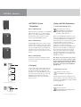
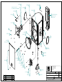
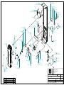
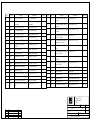
13.07.07
Service Documents
Confidential, for authorized service technicians only!
Do not disclose this information to or share these documents
with third parties.
Vertraulich! Nur für autorisierte Servicetechniker!
Nicht zur Weitergabe an Dritte freigegeben!
Note!
A.C.T.O.R
DX 112A
SAT
Achtung!
The components used in this product - particularly parts affecting
safety as well as speakers and transformers - were developed and
manufactured to certain specifications. Please use original spare
parts only to ensure the product remains fully functional and safe.
Die in diesem Produkt verwendeten Komponenten, insbesondere
sicherheitsrelevante Teile, Lautsprecher und Transformatoren
wurden nach spezifischen Vorgaben entwickelt und gefertigt.
Bitte benutzen Sie ausschließlich Original-Ersatzteile – nur so ist
die volle Funktionalität und Sicherheit gewährleistet.
TECHNICAL SERVICE:
Stamer Musikanlagen GmbH • Magdeburger Str. 8 • 66606 St.Wendel • Germany
Music & Sales P.E. GmbH • Leipziger Str. 3 • 66606 St.Wendel • Germany
Directory
features
page:
3-8
drawing-numbers-example
page:
13
standard for single wire confection
page:
14
HK1104-A.C.T.O.R DX SATELLITE 112A
page:
15
exploded drawings:
complete /active
complete /passive
chassis /active
chassis /passive
front grille
cabling 100-240V
Rev.:
Rev.:
Rev.:
Rev.:
Rev.:
Rev.:
B
B
B
B
B
B
page:
page:
page:
page:
page:
page:
16-17
18-19
20-22
23-24
25
26
inputboard
Rev.:
A
page:
27
inputboard
Rev.:
A
page:
28
layout diagrams
circuit diagrams
ACTOR DX Manual 1.1
Welcome to the HK AUDIO
family!
Thank you for choosing an HK AUDIO product.
ACTOR DX consists of two ADX 112 A mid/high units
loaded with a 12" woofer, 1. 4" driver and a DDO™
system controller, two ADX 115 A Sub subwoofers
with an onboard 1,000 W RMS Class D power amp,
and two ADX 115 Sub B subwoofers, the passive
complement to the Sub A bin.
You don't have to worry about tweaking frequencies
and finessing levels, all you have to do is set up the
system components, connect the signal-carrying
cables and the power cords, and you're ready to roll.
An HK AUDIO® active system is made up of more
than just two active cabinets; it is an end-to-end
sound reinforcement solution consisting of subwoofers, mid/high units and meticulously matched
electronic circuitry.
Our engineers developed new technologies to satisfy
the stringent requirements of such an advanced
system. With its unique and sophisticated features,
every active HK AUDIO® sound reinforcement
system stands out in the crowd of far more basic
active cabinets.
Warranty
Register your ACTOR DX using the enclosed
warranty card to extend your warranty to five years
free of charge!
Use the convenient online registration option at
www.hkaudio.com.
If you are unable to register online, please fill out the
enclosed warranty card completely and mail or fax it
to us. The registration is only valid if the warranty
registration card is filled out and returned to
HK AUDIO® or the device is registered via the
Internet within 30 days of the date of purchase.
We are also interested in learning where our devices
are used and by whom. This information will help us
design future products. Your information is of course
protected by privacy laws.
Thank you!
HK AUDIO®
Technical Service
Postfach 1509
D-66959 St. Wendel
Germany
All the best from the HK AUDIO team; enjoy your
ACTOR DX system!
Table of Contents
1
2
3
4
5
6
7
8
ACTOR DX System Components . . . . . . . . . . . .6
Transport . . . . . . . . . . . . . . . . . . . . . . . . . . . . . . .6
Setup and Cable Connections . . . . . . . . . . . . . . .6
Connections and Control Features . . . . . . . . . . .8
Tips and Tricks . . . . . . . . . . . . . . . . . . . . . . . . .10
ACTOR DX Accessories . . . . . . . . . . . . . . . . . . .11
Troubleshooting . . . . . . . . . . . . . . . . . . . . . . . . .11
Technical Specifications . . . . . . . . . . . . . . . . . . .12
5
Unique features for premium performance
Digital amping
DDO™ Controller technology
With an extremely high efficiency rating topping
the 90% mark, Class D digital power amps are
substantially smaller, lighter, and more compact than
comparable conventional amps. The reduced
thermal load on components enhances reliability,
while the far faster slew rate and higher attenuation
factor audibly enhance the speed and accuracy of the
system’s dynamic response.
The DDO™ Controller compensates for varying
response of components such as low-frequency,
midrange and high-frequency speakers, power amps,
crossovers and so forth to forge a homogenous
system with uniform dynamics and a sonic image
with sharply defined contours.
DuoTilt™
Easy Setup and Handling
– making the most of sonic energy
– for less pre-gig stress
The novel DuoTilt™ pole mount allows sound energy
to be utilized far more efficiently. DuoTilt™ offers
7.5° and 15° angles of tilt, enabling perfect mid/high
unit-to-audience alignment. Troublesome ceiling
reflections are minimized, making the sound clearer,
tighter, and more focused.
Like all HK AUDIO Active Systems, ACTOR DX
was designed as a cohesive system consisting of
perfectly matched components. Painstaking effort
was invested in ensuring ACTOR DX can be transported easily and set up quickly. Handling and EQing
couldn’t be any easier, with no complicated and
time-consuming tweaking challenges to master.
English
– for enhanced efficiency and dynamics
ACTOR DX Manual 1.1
1 ACTOR DX System
Components
ADX 112 A
ADX 112 A Mid/High Unit
These enclosures are loaded with one 12" HK AUDIO
Custom speaker and one 1. 4" compression driver
with a 60° x 40° CD horn. Delivering 600 W RMS,
the Class D power amp is housed in a separate
chamber along with the DDO™ Controller.
ADX 115 Sub A Subwoofer
ADX 115 Sub A
The ACTOR DX A Sub’s housing is split up into two
chambers. The front chamber serves as the speaker
cabinet for the 15" front-loaded loudspeaker, which
has a power handling capacity of 500 W RMS and a
nominal impedance of 8 ohms. The power amp is
housed in a separate compartment at the rear of the
cabinet.
ADX 115 Sub B Subwoofer
ADX 115 Sub B
The housings and speakers of the ADX 115 Sub Bs
and Sub A are identical. The Sub B is the passive
version of the Sub A.
2 Transport
To transport the system, simply set the subwoofers
on their casters and place the mid/high units onto
the subwoofers with the foam rubber grille side
facing down. Use original HK AUDIO‚ covers to get
your system ready to handle the rigors of the road.
Padded and protected against moisture, your
ACTOR DX system is sure to serve you well for a
long time to come.
3 Setup and Cable Connections
3.1 The Standard ACTOR DX System
The standard system comprises
two ACTOR ADX 112 A mid/high units,
two ADX 115 Sub A subwoofers and
two ADX 115 Sub B subwoofers.
Always connect ACTOR DX starting at the top and
working your way down (refer to the diagram on the
rear panel of ACTOR DX components)! This may
seem unusual if you are accustomed to working with
active systems where signals are routed via
paralleled pass-through jacks, which would allow
connections to be made in any sequence.
ACTOR DX, in contrast, features the DDO™ System
Controller housed in the ADX 112 A mid/high unit.
This controller lets you determine basic settings
such as the system configuration, the mid/high
unit’s level and the subwoofer’s level right on the
mid/high unit. DDO™ then routes signals from the
mid/high unit to Sub A.
Note: Always connect cords in the correct sequence.
Never connect a cord carrying a signal from a mixer
directly to Sub A because this bypasses the DDO™
system controller! Always connect signal sources to
the “master” system input located on ACTOR DX
mid/high units!
3.2 ACTOR DX Full-range Setup
The full-range setup comprises
two ACTOR ADX 112 A mid/high units.
Select the appropriate system configuration on the
system controller's control panel. In full-range mode,
the subwoofer output (DDO™ controlled) is disabled
to prevent handling errors.
Standard system connections
3.3 ACTOR DX Club Set
The club set comprises
two ACTOR ADX 112 A mid/high units and
two ADX 115 Sub A bins.
Connections for full-range setup
7
3.4 Dual ACTOR DX System
The dual system comprises four
ACTOR ADX 112 A mid/high units, four ADX
115 Sub A bins and four ADX 115 B Sub bins.
Connect cables from top to bottom as described
above. Plug a microphone cord into the first
mid/high unit’s THROUGH port to route the mixer
signal to the second ACTOR DX stack.
Ensure XLR connectors are wired as follows:
1= ground, 2= +, 3= -
3.6 Using the ACTOR DX Tilt Unit
Using the optional tilt unit couldn’t be easier:
Proceed as if mounting the enclosure on a pole.
Set the ACTOR DX tilt unit with the bottom plate
facing down on the upper subwoofer and then set
the ACTOR mid/high unit on it so the tilt unit’s rod
is inserted into one of the two holes (7.5° or 15°).
Club set connections
3.5 Flying ACTOR ADX 112 A Mid/High Units
Use the HK AUDIO rigging frame to fly ACTOR DX
mid/high units. To attach the frame, remove the
countersunk M10 hex head bolts from the side
panels. Bolt the rigging frame’s brackets to the
enclosure. Set the mid/high unit’s inclination to the
desired angle by loosening the knobs on the sides
and firmly hand-tightening them again. The serrated
plastic washers hold the mid/high unit in place.
Note: For reasons of safety, use tested and certified
load-securing devices only (for example, halfcouplers, TV spigots, brackets, and so forth)!
Dual system connections
ACTOR ADX 112 A with rigging bracket
Question
Can I connect speakers other than an ACTOR DX
mid/high unit to an ACTOR DX Sub A or Sub B
subwoofer?
Answer
The system components are acoustically matched
for optimum audio performance and may be
operated in the indicated configuration only. Using
other mid/high units can degrade the sound and
damage the power amp (e.g. the Sub A’s).
Sub A’s nominal impedance is 4 ohms, and
impedance may not fall short of this value. Connect
no more than one Sub B to Sub A’s speaker out.
The ACTOR DX tilt unit in action
English
Ensure wall and pole mounts are designed to handle
the load (an ACTOR ADX 112 A weighs 30 kg).
ACTOR DX Manual 1.1
4 Connections and Control
Features
5 Input Sensitivity
This selector matches the preamp’s input sensitivity
to the mixer’s output signal level.
4.1 ACTOR ADX 112 A
Engage this switch to select either -10 dB (for example, for unbalanced 1/4” jacks and consumer level
devices) or +0 dB (for example, for balanced XLR
ports and professional mixers).
1 Power Switch
Handling: This is the on/off switch for the active
system. When engaged, the system controller’s
display lights up orange.
Always switch the ACTOR DX active system on last,
that is, after powering up all other components, and
switch it off first before powering down all other
connected devices.
2 Mains Input
Connecting cords: Use the factory-included Powercon cable to connect this socket to a wall receptacle.
Caution! Make sure the local mains voltage matches
the voltage specified on the device. If you connect
the system to the wrong mains voltage, you may
destroy the ACTOR DX system’s electronic
components.
3 Link (only 220-240 V version)
Connecting cords: The Powercon Link socket is wired
in parallel to the Mains Input. Connect other load
consumers (for example, another ACTOR DX
mid/high unit or an ACTOR DX Sub A bin) to it.
Heads up: The Powercon Link socket can handle
loads up to 8.6 A and 2060 W (at 230 volts). This
means you can use it to power up to but no more
than two additional ACTOR DX components.
1
4
5
6
7
Note: Always switch on ACTOR DX components one
after another to prevent a sudden spike in the
venue’s power supply. Otherwise the power surge
may cause the house circuit breaker to trip.
12
11
2
8
13
3
9
10
14
ACTOR ADX 112 A
9
4 Ground
Ground lift button for separating the signal and
chassis ground in the event of humming noises.
In the event of low-frequency hum, engage the
Ground Lift switch. The ground circuit is severed
when this button is pressed. If this doesn’t solve the
problem, check all cords connected to ACTOR DX as
well as all signal cables routed to the mixing console
for damage (see also Tips and Tricks).
Recommendation: Select +0 dB when using a
professional-grade mixer sporting balanced outputs.
This lets you take advantage of console faders’ full
control range and helps prevent overloads.
Opt for -10 dB A when using a console with a lower
output level (unbalanced 1/4" output).
6 Input Overload
This LED lights up when the input level is too high
and the entire system (preamp and controller) is
being overdriven. Not only does this result in
unpleasant distortion, it can also harm the system’s
components. If the red LED lights up, reduce the
level (volume) at the mixer!
7 Line In
Connecting cords: Connect cords carrying signals
from your mixer (master left/right, line out, or a
similar circuit) to the balanced inputs using a mic
cord equipped with XLR connectors.
Ensure XLR connectors are wired as follows:
1= ground, 2= +, 3= -.
8 Through
Connecting cords: Use this parallel output to route
the incoming line signal to other components (for
example, to additional ACTOR DX mid/high units)
via XLR cords.
9 Limiter LEDs
These are the active system’s "rev counters," serving
to indicate the limiter’s operating status.
10 Subwoofer Output
Connecting cords: Use this output to send the
subwoofer signal from the DDO™ controller to an
ACTOR ADX 115 Sub A via an XLR cord.
Ensure XLR connectors are wired as follows:
1= ground, 2= +, 3= -.
9
11 Display
Read-out: The numeric display indicates the
currently selected system configuration.
0 Mute
1 Top only
2 Half Stack DJ
3 Half Stack Band
4 Full Stack DJ
5 Full Stack Band
6 Dual Stack DJ
7 Dual Stack Band
1 mid/high unit Full-range mode
1 mid/high unit, 1 Sub A
1 mid/high unit, 1 Sub A
1 mid/high unit, 1 Sub A+ Sub B
1 mid/high unit, 1 Sub A+ Sub B
2 mid/high units, 2 Sub A+ Sub B
2 mid/high units, 2 Sub A + Sub B
L Locked
U Unlocked
buttons are disabled
buttons are enabled
14 Subwoofer Level
Operation: When the knob is set to the 12 o’clock
position, the subwoofer’s and the mid/high unit’s
respective volumes are matched, ensuring bass and
mid/high ranges are rendered in balanced musical
proportion. If desired, twist the Subwoofer Level
knob to the left to decrease and to the right to
increase the subwoofer’s level by up to 6 dB.
Tip: If necessary or desired, use the Subwoofer Level
knob to boost or cut bass frequencies below 100 Hz
rather than resorting to the mixer’s master EQ.
15 Rigging Points
Attach the ACTOR DX rigging frame here to fly the
mid/high unit from a truss or similar suspension
device.
4
5
6
1
7
11
12
8
2
13
9
3
10
9
12 Up/Down Buttons
Use these buttons to select system configurations.
14
Operation: To enable the buttons, press Up and
Down simultaneously and hold for about one to two
seconds. The letter U (for unlocked) appears briefly
in the display. Now you can press Up and/or Down
to select the desired setup (see the table above). The
buttons are automatically disabled soon thereafter.
The letter L (locked) appears briefly in the display.
ACTOR ADX 112 A control features
11
13 Top Level
Operation: Use this knob to determine the volume of
the mid/high unit. The standard setting is 0 dB at
the 12 o’clock position. This means the level is
neither boosted nor cut.
13
More about limiter LEDs
A dedicated LED indicates the limiter status for the
mid/high-range signal path and the subwoofer
circuit, respectively.
What do the lights mean?
The green LED indicates that the given input is
receiving a signal. As long as the LED lights up
green, the system is operating at low-to-medium
levels, with plenty of headroom available for the
power amps. Yellow indicates that the system is
being pushed close to its threshold. The yellow LED
may flash at regular intervals, but it may not
illuminate continuously. If it does this, back off the
volume on your mixer.
If the LED constantly lights up red, there is a
problem in the power amp and the system will shut
down. In this case, have a qualified service
technician check the device.
9
9
14
Control features of the ACTOR DX system controller
English
12
ACTOR DX Manual 1.1
4.2 ACTOR ADX 115 Sub A
3
1
1 Power Switch
Operation: This is the on/off switch for the active
system. When engaged, the Power On LED lights up
red. Always switch the ACTOR DX active system on
last, that is, after powering up all other components,
and switch it off first before powering down all other
connected devices.
4
2
2 Mains Input
Connecting cords: Use the factory-included Powercon cord to connect this socket to a wall receptacle.
Caution! Make sure the local mains voltage matches
the voltage specified on the device. If you connect
the system to the wrong mains voltage, you may
destroy the ACTOR DX system’s electronic
components.
5
Control features of the ACTOR ADX 115 Sub A
3 Power On LED
This LED lights up when the Power switch is set to
ON and the system is connected to a mains power
supply.
4 Subwoofer Input
Connecting cords: To patch the signal from the
DDO™ controller to a Sub A bin, plug one end of a
mic cord equipped with XLR connectors into the
mid/high unit’s Subwoofer output and the other into
the Subwoofer Input. Ensure XLR connectors are
wired as follows: 1= ground, 2= +, 3= -.
6
Note: Never patch the mixer's line and/or master
signal directly into Sub A’s Subwoofer Input. This
bypasses the system’s controller, crossover, equalization and protection circuitry, risking serious damage
to the subwoofer. Read chapter 3, Setup and Cable
Connections, for more on this.
5 To Sub B Speaker Output
Connecting cords: Use this parallel Speakon® output
to connect a passive ACTOR DX B Sub bin.
Control features of the ACTOR ADX 115 Sub B
Note: Be sure to twist the Speakon“ connectors
clockwise until they lock in place! You must first disengage the safety catch before you can unplug the
connector. To do this, pull the bayonet catch towards
the cord. Pin assignments are pin 1+ = +, pin 1- = -.
Feel free to use a four-core cable if you wish, though
pin 2+ and 2- remain unused, of course.
4.3 ACTOR ADX 115 Sub B
6 Sub B In
Connecting cords: Connect the Speakon® input to
the ADX 115 Sub A bin’s Speaker Output using a
suitable loudspeaker cord.
5 Tips and Tricks
Do not expose electronic circuitry to moisture! When
you set the system up outdoors, be sure to protect it
against rain. Keep soft drinks, beer and all other
liquids well away from the cabinets to protect their
electronic components from short circuits.
Ensure that the ducts on the enclosures’ rear panels
are free of dirt and the devices are ventilated
properly. Otherwise, electronic components may
overheat and suffer damage.
ACTOR DX delivers optimum sound, so you should
provide it with optimum input signals! Noise such as
humming is generally caused by defective cables, the
wrong type of cords, or unbalanced signals routed
into the mixing console. Check all signal and mains
cables.
Prevent distortion! Not only is it unpleasant to your
audience’s ears, it also endangers your equipment.
Make sure all components that are connected
directly and indirectly to ACTOR DX have sufficient
power ratings, and that they don’t distort because
they‘re running at their respective limits. Provide an
undistorted signal to the system that doesn’t have to
be cleaned up by backing off the Gain knob.
Avoid ground loops! You may encounter a ground
loop when the mixer is grounded via a mains cord
which isn’t connected to the same mains circuit as
ACTOR DX. To prevent this problem, always connect
the ACTOR DX system and the mixing console to the
same electrical circuit (same phase!). If your equip-
11
CAUTION: Never tape over the plug’s ground
terminalæthis endangers lives!
6 ACTOR DX Accessories
HK AUDIO ACTOR DX Tilt-Unit
Designed to hold the ACTOR DX mid/high unit, the
tilt unit is placed on the subwoofer, with the
DuoTilt™ fitting offering a choice of 7.5° or 15°
angles.
HK AUDIO Dust Covers for ACTOR DX
This set comprises subwoofer and satellite covers.
Extremely tear resistant, water repellant and thickly
padded, these covers afford lasting protection for the
ACTOR DX system during transport.
HK AUDIO ACTOR DX Rigging Frame
Easy-to-mount U bracket for attaching half-couplers,
TV spigots and clamps.
To learn more about original HK AUDIO accessories,
talk to your HK AUDIO dealer or visit
www.hkaudio.com.
7 Troubleshooting
The Power On LED or display does not light up red
when switched on.
1 Check if the power cord is plugged into the Mains
Input.
2 Check if the mains power supply is providing
current.
3 Check if the house circuit breaker has tripped.
The Power On LED lights up red, but the cabinets
produce no sound.
1 Check the cords connected to the inputs.
2 Check if the signal sources (mixer, keyboard, CD
player, etc.) are on.
3 Are the Gain knobs turned up?
4 Check the speaker cords for damage.
5 Check if the Speakon“ connectors are locked
(twisted to the right). An electrical connection is
established only if their locking mechanism
engages.
The subwoofer’s low frequency output is weak.
1 Check the setting of the Subwoofer Level knob. Set
Sub A’s volume to the desired level using the
Subwoofer Level.
2 Check if the system configuration "Top Only" is
selected on the system controller. This mutes the
subwoofers.
The signal sounds distorted.
1 Check the LED displays on your mixer. Ensure they
are not constantly in the red. If necessary, back off
the volume at the mixer.
2 If the LED displays on your mixer are in the green,
but the sound is still distorted, back off the Level
knobs on the ACTOR ADX 112 A enclosures.
3 Observe the Input Overload indicator and the
Limiter LEDs on the ACTOR DX mid/high units’
control panels. It is acceptable for these to flash
yellow from time to time, but under no
circumstances may the yellow LEDs illuminate
continuously. If they do, turn down the Level
knobs. Check also the Input Sensitivity setting.
If the signal is saturated, set it to +0 dB.
Annoying hum
1 Check the cords connecting the signal source to
ACTOR DX. Replace damaged cords.
2 If you cannot pinpoint the cause of the humming,
engage Ground Lift. This should remedy the
problem in most cases.
English
ment hums despite this precaution, the Ground Lift
switch can be a great help.
ACTOR DX Manual 1.1
8 Technical Specifications
ACTOR ADX 112 A
Connections:
Line In:
Input:
Input impedance:
Sensitivity:
Max. input level:
Frequency response +/- 3dB:1)
Axial sensitivity 1W@1m:2)
Maximum SPL @1m: 2)
Mid/high-range amplifier:
Active protective circuits:
Midrange speaker:
Tweeter/ driver:
Directivity:
Crossover frequency:
Pole mount:
Rigging points:
Accessories:
Dimensions (WxDxH):
Weight:
General electrical data:
Protection class 1 (protectively earthed)
Max. current consumption:
Max. power consumption:
Mains voltage range:
Ambient temperature range:
Internal fuses:
1x XLR Line In
1x XLR Line Through
1x XLR Subwoofer Output
XLR female (pin 1= Ground; 2= +, 3= -)
Electronically balanced & floating
20 k ohms
Switchable from –10 dB to 0 dB (= +4 dBu)
+22 dBu
80 Hz – 19 kHz full-range mode
130 Hz – 19 kHz Stop-only mode
106 dB
129 dB @ 10% THD
1x 600 W RMS/ Class D
DDO™ Controller Multiband Limiter, Subsonic Filter
12"
1.4"
60° x 40° CD horn
950 Hz, 12 dB/octave
HK AUDIO DuoTilt™, 36 mm, 7.5°, 15°
4 M10 threaded bushings for attaching an optional
rigging bracket
ACTOR DX Tilt-Unit, 7.5°, 15°
39 cm x 65 cm x 42 cm
15 1/4" x 25 5/8" x 16 1/2"
32 kg/ 70.6 lbs.
4.4 A (230 V)
8 A (120 V)
8 A (100 V)
1000 VA
+/- 10%
-10° C to +35° C
T8A
1) Via active crossover
2) All measurements taken under half-space conditions
13
This is to certify that
HK AUDIO® ACTOR DX
ACTOR ADX 115 Sub A
Subwoofer Input:
Input:
Input impedance:
Sensitivity:
Max. input level:
Frequency response +/- 3dB: 1)
Axial sensitivity 1W@1m: 2)
Maximum SPL @1m: 2)
Subwoofer amplifier:
Active protective circuits:
Woofer:
Pole mount:
Castors
Dimensions (WxHxD):
Weight:
General electrical data:
Protection class 1 (protectively earthed)
Max. current consumption:
Max. power consumption:
Mains voltage range:
Ambient temperature range:
Internal fuses:
1x XLR Subwoofer Input
1x XLR Subwoofer Through
1x Speakon® Parallel Out
XLR female (pin 1= Ground; 2= +, 3= -)
Electronically balanced & floating
20 k ohms
+10 dBu (turned all the way up)
+22 dBu
48 Hz – 130 Hz
104 dB
126 dB @ 10% THD
1x 1,000 W RMS / Class D
DDO™ Controller, Multiband Limiter, Subsonic Filter
15"
M20 thread base plate
Four 100 mm castors on the rear panel
48 cm x 65 cm x 66 cm incl. castors
18 7/8" x 25 5/8" x 26"
36.6 kg/ 80.0 lbs.
13 A (230 V)
8 A (120 V)
8 A (100 V)
1000 VA
+/- 10%
-10° C to +35° C
T8A
Weight:
Stamer Musikanlagen
GmbH*
Magdeburger Str. 8
66606 St.Wendel
Lothar Stamer Dipl.Ing.
Managing Director
St.Wendel, 04/15/05
* Stamer Musikanlagen manufactures exclusively
for HK AUDIO®.
ACTOR ADX 115 Sub B
Connections:
Nominal power handling:
Frequency response +/- 3dB: 1)
Axial sensitivity t 1W@1m: *)
Maximum SPL @1m: *)
Woofer:
Pole mount:
Castors
Dimensions (WxHxD):
complies with the provisions of the Directive of
the Council of the European Communities on the
approximation of the laws of the Member States
relating to electromagnetic compatibility
(EMC Directive 89/336/EEC) and the low voltage
Directive (73/23/EEC).
This declaration of conformity of the European
Communities is the result of an examination carried
out by the Quality Assurance Department of
STAMER GmbH in accordance with European
Standards EN 50081-1, EN 50082-1and EN 60065
for low voltage, as laid down in Article 10 of the
EMC Directive.
1x Speakon® Input
500 W RMS/ 8 ohms
48 Hz – 130 Hz
104 dB
126 dB @ 10% THD
15"
Four 100 mm castors on the rear panel
48 cm x 65 cm x 66 cm incl. castors
18 7/8" x 25 5/8" x 26"
33.7 kg/ 74.3 lbs.
English
Connections:
DRAWING-NUMBERS
EXAMPLE
HK0106-EX-R01-1A
REVISION
VERSION
SERIAL NUMBER
DEPARTMENT:
R = R&D
CHARACTER:
BL = SHEET METAL / BLECH
EX = EXPLODED DRAWING / EXPLOSIONSZEICHNUNG
HZ = CABINET / HOLZGEHÄUSE
KU = PLASTIC / KUNSTSTOFF
LP = PCB / LEITERPLATTEN
SO = MISCELLANEOUS / SONSTIGES
SP = SCHEMATIC / SCHALTPLÄNE
TR = TRANSFORMER / TRANSFORMATOR
GK = WIRING DIAGRAM / GERÄTEVERKABELUNG
PROJECT-NR.:
HK = HK AUDIO
HU = HUGHES&KETTNER
MP = MINDPRINT
Stand
17. Jun 04
Standard for single wire confection.
16
B
150
638
I
-
485 W
Z
I
1015
style 1015 according UL specifications
I = completely insulated with black shrinktube or appropriate sleeve
IT = partly insulated; only crimp connection insulated.
no marking = without insulation
Z = with additional junction
no marking = without additional junction
W = angled faston
no marking = straight faston
Faston connector brass tin-plated DIN 46245
638 = 6,3 * 0,8 [mm]
488 = 4,8 * 0,8 [mm]
485 = 4,8 * 0,5 [mm] if fully insulated (I) insulation with blue shrinktube
if partly insulated (IT) use IF 602 485 .
288 = 2,8 * 0,8 [mm]
285 = 2,8 * 0,5 [mm] if fully insulated (I) insulation with blue shrinktube
if partly insulated (IT) use IF 602 485
abiso = 5mm bared and tin-plated (teilabzug)
text for special constructions, (for example. 4mm ringshaped faston)
the larger faston connector always mentioned at first. (Nathan drawing number controlling)
lenght in mm within a 50 mm raster
colour
B = black (phase conductor)
R = red
BR = brown
BL = blue (neutral conductor)
W = white
YG = yellow-green (ground bonding/ earthing connection)
cross section
16 = AWG 16 (prefered usage)
Q1.5 = H07VK 1,5mm² (prefered usage)
wire designation:
P + lfd Nr. = AWG single wire black, red, blue, brown or white
E + lfd Nr. = AWG single wire green- yellow
L + lfd Nr. = twisted AWG double wire, lenght specification always in twisted condition
FQL + lfd Nr. = crossover wiring H07VK
Regarding special wirings like wiring harness or similar, drawings will be prepared and appropriate
drawing numbers will be stored in the article archive.
Service Documents
HK1104
A.C.T.O.R
DX 112A
Satellite
Confidential, for authorized service technicians only! Do not disclose
this information to or share these documents with third parties.
TECHNICAL SERVICE:
Stamer Musikanlagen GmbH • Magdeburger Str. 8 • 66606 St.Wendel • Germany
Music & Sales P.E. GmbH • Leipziger Str. 3 • 66606 St.Wendel • Germany
E 994178 28
SCHWINGSPULE ALS ERSATZTEIL:
994191-B&M MD/DE 254 8OHM MEMBRANA
E 974381 17
E 974355 16
E 976159 23
E 972008 5
E 974227 13
E 974099 11
3 E 502180 (220-240V)
E 502181 (100-120V)
HK1104-EX-R03-1B
E 994177 27
8
E 972047 6
E 976072 21
17
E 994217 29
23
E 1124 1
HK1104-EX-R04-1B
16
2 E 400263
HK1104-HZ-R01-1C
20 E 976009
12 E 974218
E 976001 19
E 974258 14
E 974314 15
E 974068 9
E 974454 18
E 974006 7
TITEL:
22 E 976113
E 974095 10
INDEX ÄNDERUNG
1B-210607 update for service manual
ZEICHNER
C. Loris
E 520118 4
8 E 974013
ACTOR DX SATTELITE
EXPLODED DRAWING
COMPLETE
66606 St. Wendel / Germany
ZEICHNUNGS-NR.:
ERSTELLT VON:
VERSION:
HK1104-EX-R05-1B
C. LORIS
1
AM:
21.06.07
AM:
GEPRÜFT/
FREIGEGEBEN VON:
WERKSTOFF:
DATEINAME:
OBERFLÄCHE:
HK1104-EX-R05-1B-GESAMT-TOP
REVISION:
BLATT:
2
B
1
BLÄTTER
pos. no.
part-no. 1
part-no. 2
description
Beschreibung
quantity
1
1124
front grille Actor DX sattelite
Frontgitter Actor DX Top
1
2
400263
wooden cabinet, ACTOR DX Top
Holzgeh. ACTOR DX Top
1
3
502180
(220-240V)
chassis Actor DX sattelite
Chassis Actor DX Top
1
4
520118
crossover Actor DX sat
Freqw. Actor DX Top
1
5
972008
damping wool
Dämmwolle Hochbauschvlies
1
6
972047
PE-foam tube
PE-Schaumstoff-Röhrchen
10
7
974006
hexagon socket head cap screw, M5x25,
black
Inbusschraube M5 x 25sw
7
8
974013
hexagon socket countersunk head screw,
M6x20, black
Inbussenkschraube M6x20 sw
10
9
974068
washer, form A, D=5.3mm, zinc plated
Unterleg-Scheibe 5,3 vz
1
10
974095
ABC-Spax S, countersunk head, Pozidrive,
4x35, black
Spax Senkkopf, 4*35 sw
4
11
974099
Mechanical locking screw, TENSILOCK W151,
M6x20
Sperrzahnschraube
Tensilock W151
4
12
974218
ABC-Spax-S chipboard screw, panhead Z,
5x20, black
Pan Head-Z ABC-Spax sw 5*20
4
13
974227
hexagon nut, class 8, M6, zinc plated
Sechskantmutter M6 vz
4
14
974258
hexagon socket head cap screw, M5x40,
black
Inbusschraube M5 x 40 sw
1
15
974314
ABC-Spax-S screws for backwall, 4x40, black Rückwandschraube, 4*40 sw
2
16
974355
cross recessed panhead tapping screw with
collar, 3.9x30, black
Blechschr. KFR-Kopf 3,9* 30 sw
5
17
974381
hexagon socket countersunk head screw,
M10x35, black
Inbussenkschraube M10x35 sw
4
18
974454
plastic PCB spacer, 6.2x10x10, Polyamid black Dist.Hülse PE
19
976001
rubber foot square, self-adhesive, black
Gummifuss quadr. selbstkleb. sw
1
20
976009
rubber foot D38*H11 [mm]
Gummifuss D38*H11 [mm]
4
21
976072
rubber bumper D=15/13 H=10
Gummi Bumper D=15/13 H=10
2
22
976113
flange for speaker stand, plastic, DuoTilt
Ständerflansch, Kunst., zweifach
1
23
976159
plastic dish Premium One
Griffinnenschale Premium One
2
24*
982037
sealing tape 2x6mm
Iso-Zell-Band fadenvers. 2*6mm
2,42 lfdm
25*
986015
foam glue, Jowatac
Schaumstoffklebstoff Jowatac
xxx
26*
988165
1k polyurethane glue, 310mltrs. tube
Polyurethan 1-K Kleber, 310ml
Kartusche
xxx
Horn 10HR drehbar 60°x40° 1,4"
1
27
994177
502181
(100-120V)
Horn 10HR drehbar 60°x40° 1,4"
M 6*20 vz,
6,2*10*10[mm]
1
TITEL:
66606 St. Wendel / Germany
ZEICHNUNGS-NR.:
ERSTELLT VON:
INDEX ÄNDERUNG
1B-210607 update for service manual
ZEICHNER
C. Loris
28
994178
B&C DE250-14-8, 1.4" HF compression driver
B&C DE254 8Ohm
1
29
994217
SICA LP 312.75/1800 WT 8 Ohms
SICA LP 312.75/1800 WT 8 Ohms
1
ACTOR DX SATTELITE
EXPLODED DRAWING
COMPLETE
VERSION:
HK1104-EX-R05-1B
C. LORIS
1
AM:
21.06.07
AM:
GEPRÜFT/
FREIGEGEBEN VON:
WERKSTOFF:
DATEINAME:
OBERFLÄCHE:
HK1104-EX-R05-1B-GESAMT-TOP
REVISION:
BLATT:
2
B
2
BLÄTTER
14 E 970638
E 970744 16
HK0502-BL-R04-1A
HK1104-BL-R01-1D
19 E 974007
8 E 950060
E 970745 17
HK1104-BL-R04-1A
13 E 966046
12 E 966001
E 974110 23
E 970739 15
HK1104-SO-R01-1B
E 943230 6
E 600080 4
28 E 974444
HK1104-SO-R06-1A
22
E 974075 20
24 E 974157
E 600079 3
31 E 976141
E 950055 7
29 E 976007
27
E 959052 11
25
23
E 547053 1
23
23
18 E 970773
HK0502-BL-R14-1B
23
22 E 974100
23
E 547053 2
E 976135 30
E 974362 27
9 E 952141
21 E 974084
10 E 952153
only for 230V
E 974197 25
E 931304 5
TITEL:
26 E 974290
ACTOR DX SATTELITE
EXPLODED DRAWING
CHASSIS
66606 St. Wendel / Germany
ZEICHNUNGS-NR.:
ERSTELLT VON:
INDEX ÄNDERUNG
1B-200607 update for service manual
ZEICHNER
C. Loris
VERSION:
HK1104-EX-R03-1B
C. LORIS
1
AM:
20.06.07
AM:
GEPRÜFT/
FREIGEGEBEN VON:
WERKSTOFF:
DATEINAME:
OBERFLÄCHE:
HK1104-EX-R03-1B-CHASSIS-TOP
REVISION:
BLATT:
3
B
1
BLÄTTER
pos. no.
part-no. 1
description
Beschreibung
quantity
pos. no.
20
974075
cross recessed panhead screw, M3x5,
zinc plated
Linsenschraube M3x5 vz
2
21
974084
cross recessed panhead screw, M3x8,
zinc plated
Linsenschraube M3 x 8 vz
2
22
974100
toothed lock washer, D=3,2, AZ, black
zinc plated
Fächer-Scheibe az, 3,2 sw vz
4
23
974110
self locking hexagon nut with plastic
insert, M3, zinc plated
Stopmutter M3 vz
14
24
974157
cross recessed raised countersunk
tapping screw, 2.9x9.5, black
Blechschr. Senk-Li 2,9*9,5 sw
6
25
974197
hexagon PCB spacer, type B, M3x8, zinc Dist. Bol Innen/Außengew. M3*8 vz
plated
4
26
974290
self locking hexagon nut with plastic
insert, M4, zinc plated
Stopmutter M4 vz
4
27
974362
hexagon PCB spacer, type B, M3x12,
zinc plated
Dist. Bol Innen/Außengew. M3*12 vz
4
28
974444
cross recessed raised countersunk
screw, M3x12, black
Linsensenkschraube M3*12 sw
4
29
976007
cable tie 2,5x100 (mm)
Kabelbinder natur 2,5x100 (mm)
9
30
976135
socket for cable tie
Schraubsockel
2
31
976141
rubberbuffer 15x15 B
Gummipuffer GM-Puffer 15x15 B
4
32*
982044
sealing tape 2x15mm
Iso-Zell-Band fadenvers. 2*15mm
0,15 lfdm
33*
986002
foam glue, Simalfa
Schaumstoffklebstoff Simalfa
34*
988206
pre-cut part transfer tape 1573
Transferbandzuschnitt 1573
1
547053
Actor DX Top Mainboard
Actor DX Top Mainboard
1
2
547053
ADX112A Displayboard Assembly (part
of mainboard)
ADX112A, Bedienpanel Baugruppe (Teil
von Mainboard)
1
3
600079
mains filter, DEACON / ACTOR
Netzfilter Deacon 230-100V
1
4
600080
60 Interfaceboard Deacon
60 Interfaceboard Deacon
1
5
931304
ferrite teroid core, 25x15x12
Ferritring, geschlossen 25x15x12
1
6
943230
dust filter, ACTOR DX "R06"
Staubschutz, ACTOR DX "R06"
1
7
950055
Slide Switch 2xum T22205B
Schiebeschalter 2xum T22205B
1
8
950060
hi-inrush, mains rocker switch,
C13150VB
Netzschalter gross C1350VB
1
9
952141
mains inlet PowerCon
Netzbuchse Power Con Inlet
1
10
952153
mains outlet PowerCon
Netzbuchse Power Con Outlet
1
11
959052
PWM power amp 100-230Volt
PWM Endstufe 100-230Volt
1
12
966001
knob round/conical. grey
Knopf-Taster rund/kon. grau
1
13
966046
plunger type key top, 9*9, B32-1210
Knopf-Taster 9*9 B32-1210
2
14
970638
sheet metal Deacon cover panel
Blech Deacon Abdeckplatte
1
15
970739
Plexiglas ACTOR DX Top
Plexiglas ACTOR DX Top
1
16
970744
Sheet Metal Chassis, ACTOR DX Top
Blech Chassis Actor DX Top
1
17
970745
ACTOR DX, sheet metal air guide
Blech Actor DX Lüftungskanal
1
18
970773
DEACON / ACTOR insulation plate
DEACON Blech Isolierplatte
1
19
974007
hexagon socket oval head screw, M3x6, Linsenschr.m.Innens. M3*6 sw
black
2
part-no. 1
description
Beschreibung
TITEL:
quantity
0,20 lfm
ACTOR DX SATTELITE
EXPLODED DRAWING
CHASSIS
66606 St. Wendel / Germany
ZEICHNUNGS-NR.:
ERSTELLT VON:
INDEX ÄNDERUNG
1B-200607 update for service manual
ZEICHNER
C. Loris
VERSION:
HK1104-EX-R03-1B
C. LORIS
1
AM:
20.06.07
AM:
GEPRÜFT/
FREIGEGEBEN VON:
WERKSTOFF:
DATEINAME:
xxx
OBERFLÄCHE:
HK1104-EX-R03-1B-CHASSIS-TOP
REVISION:
BLATT:
3
B
2
BLÄTTER
5
11
16
3
9
10
18
1
16
4
7
2
TITEL:
ACTOR DX SATTELITE
EXPLODED DRAWING
CHASSIS
66606 St. Wendel / Germany
ZEICHNUNGS-NR.:
ERSTELLT VON:
INDEX ÄNDERUNG
1B-200607 update for service manual
ZEICHNER
C. Loris
VERSION:
HK1104-EX-R03-1B
C. LORIS
1
AM:
20.06.07
AM:
GEPRÜFT/
FREIGEGEBEN VON:
WERKSTOFF:
DATEINAME:
OBERFLÄCHE:
HK1104-EX-R03-1B-CHASSIS-TOP
REVISION:
BLATT:
3
B
3
BLÄTTER
pos. no.
part-no. 1
description
Beschreibung
quantity
1
970335
sheet metal front grille
Streckgitter
1
2
972085
acoustic foam anthracite 15mm
Akustikschaum Anthrazit 15mm
1
3
974158
snapon retaining ring (for logo)
Schnellbefestiger f. Logo
1
4
980105
logo ´HK Audio´ 55x55 mm
Logo ´HK Audio´ 55x55 mm
1
1 E 970335
HK1104-SO-R03-1C
3 E 974158
E 972085 2
HK1104-SO-R05-1C
TITEL:
E 980105 4
66606 St. Wendel / Germany
ZEICHNUNGS-NR.:
ERSTELLT VON:
INDEX ÄNDERUNG
1B-200607 update for service manual
ZEICHNER
C. Loris
HK1104-EX-R04-1B
C. LORIS
GEPRÜFT/
FREIGEGEBEN VON:
WERKSTOFF:
DATEINAME:
ACTOR DX SATTELITE
EXPLODED DRAWING
FRONT GRILLE
VERSION:
1
AM:
20.06.07
AM:
OBERFLÄCHE:
HK1104-EX-R04-1B-FRONTGITTER-TOP
REVISION:
BLATT:
1
B
1
BLÄTTER
!∀##
45
6&7!8∗+9∗:
2∗∗
∋∗2!−!.
9;+8∗+!/−//
!∀##
∗++28+2!.,∗+!
.∗/∃
<=<)5
≅
>?
−∗
+∗∀
∗
?
!∀
() ∋(
∗
∗
∗(
+,−./01.,.
.//+%301.,.!+4−5
0!6+,−72!01.,.
12
12
12
#∃%
%
&
%%
(
∃%∃∃&∃∃∋(
)∗+, ∗−!./0!&
1∋
2∗3∗!∀∗+
2∗3∗!∀∗+
∃∃
∃∃
%∋
1∋)∗+, ∗−!.&
∋
∋
45
6#&78∗+9∗:
2∗∗
∋∗2−.
9;+8∗+/−//
!∀
∀##
∗++28+2.,∗+
.∗/∃
<=<)5
≅
>?
−∗
+∗
∗
?
!∀
() ∋(
#∃%
%
&
%%
(
!∀#∃%∃∃&∃∃∋(
)∗+,∗−./0&
)
!∀1∀#
2∗3∗∗+
2∗3∗∗+
∃∃
∃∃
%∋
!∀1∀#)∗+,∗−.&
)
#
∋
5
5
5
4
5
4
9
9
5
2
1
2
5
8
6
12
3
11
TITEL:
12
7
10
66606 St. Wendel / Germany
ZEICHNUNGS-NR.:
ERSTELLT VON:
INDEX ÄNDERUNG
ZEICHNER
GEPRÜFT/
FREIGEGEBEN VON:
WERKSTOFF:
DATEINAME:
HK1104 - A.C.T.O.R. DX
Bestückungsplan Mainboard
VERSION:
REVISION:
HK1104-LP-R01-1D
1
D
BLATT:
AM:
Michael Bohlender
22.06.2005
1
AM:
Michael Bohlender
22.06.2005 2 BLÄTTER
FR4, zweiseitig, 1.6mm OBERFLÄCHE: HAL, Lötstop zweiseitig
HK1104-LP-R01-1D-Bestueckung
TITEL:
66606 St. Wendel / Germany
ZEICHNUNGS-NR.:
ERSTELLT VON:
INDEX ÄNDERUNG
ZEICHNER
GEPRÜFT/
FREIGEGEBEN VON:
WERKSTOFF:
DATEINAME:
HK1104 - A.C.T.O.R. DX
Bestückungsplan Mainboard
VERSION:
REVISION:
HK1104-LP-R01-1D
1
D
BLATT:
AM:
Michael Bohlender
22.06.2005
2
AM:
Michael Bohlender
22.06.2005 2 BLÄTTER
OBERFLÄCHE:
FR4, zweiseitig, 1.6mm
HAL, Lötstop zweiseitig
HK1104-LP-R01-1D-Bestueckung
1
2
4
3
Date
Modification
Revision
24.02.2005 1st draft published to EPA
1A
M. Bohlender
Name
07.03.2005 Signal LED's TOP/BASS assignment changed
1B
M. Bohlender
R8 to -15V, R27=1k5, C42=33nK, R29=1k2
D
D
BR5, BR6 = NA, BR7 changed to R12a (10k)
BR2, R10, R12, R7, R9, C36, C37, R82 = NA
Analog_Interface
HK1104-SP-R01-1D-02AnalogIO.Sch
Digital_Interface
HK1104-SP-R01-1D-03DigitalIO.Sch
R75, R88, R83 = 22k, C39/C40 = 10u/63V Elko
INPUT
BR7 added parallel to C37, R32/R39=1k5/1W
TOP_OUTPUT
TOP_OUTPUT
TOP_OUTPUT
TOP_OUTPUT
R31, R86a NA removed
SUB_OUTPUT
SUB_OUTPUT
SUB_OUTPUT
SUB_OUTPUT
DETECT_TOP
DETECT_SUB
DETECT_TOP
DETECT_SUB
INPUT
02.05.2005 R1/R2 = 12k, R44/R45 = 4k7, R33/R34 = 12k
1C
M. Bohlender
1D
M. Bohlender
R74/R83 = 8k2, C24/C25 set to NA
22.06.2005 LM324 and peripheral components removed
Relais circuit added for sensitivity setting
filter stage for unbalanced sub output removed
C
+15V
-15V
AGND
MUTE
+5V
MUTE
CHASSIS
LIMIT
DGND
PROTECT
LIMIT
CHASSIS
DGND
+5V
AGND
-15V
PROTECT
+15V
C
B
B
NA = not assembled part ----- EX = exclusive part, no alternative allowed
HT = high temperature part, assemble with distance from PCB
Title:
HK1104 -- ACTOR DX
Satellite Mainboard & Inputs
66606 St. Wendel / Germany
Number: HK1104-SP-R01-1D
1
2
Page: 1
Checked by: Michael Bohlender
Date: 22.06.2005
3
HK1104-NZ-R01, always use latest revision
Filename: HK1104-SP-R01-1D-01Main.Sch
3
Revision: D
Date: 24.02.2005
PCB No.:
All rights reserved. No part of this schematic may be reproduced, stored in a retrieval system, transmitted in any form or
by any means, electronic, mechanical, photocopying, recording or otherwise, without the prior permission of the author.
Version: 1
Michael Bohlender
Drawn by:
A
4
Pages
A
1
2
3
4
5
6
7
8
R33
47p/100V-K
SW2B
PBN-S2A3.5NIL-A-AG
1
3
6
4
SW2A
5
2
VCC
1
INPUT
3
U3A
MC33079P(MOT)
-15V
R34
12K
4K7
C18
-15V
REL1C
TQ2-12V-1
47pF/100V-K
R6
20K
R11
20K
BL01RN1A1F1J
R12
SUB_OUTPUT
10u/63V
4
2
3
1
47p/100V-K
47p/100V-K
3
4
C9
C
C13
47p/100V-K
FB6
BL01RN1A1F1J
8
-
U3B
MC33079P(MOT)
10K
5
R86
R75
22K
6
+
7
-
10K
NA
R88
22K
C21
DDO Top Output
C11
REL1B
TQ2-12V-1
R57
47R
JP3
XLR/M-NC3MBH
BL01RN1A1F1J
2
C40
R53
47R
+
9
10u/63V
C39
47p/100V-K
SUB_OUTPUT
22p/100V-K
D1
2
4
+5V
REL1A
B
R4
1K0
TOP OUT
R50
560R
DGND
DGND
R94
D10
10K
3K9
1N4148
+15V
-15V
+15V
U5
LTV817
+15V
U1A
MC33078N(ST)
8
47R
3
R31
R74
R82
10K
10K
NA
8K2
2
VCC
U1B
MC33078N(ST)
+15V
+
-15V
+15V
DGND
R25
1MEG
6
-
7
U2B
TL072CN
DETECT_TOP
1K2
NA = not assembled part ----- EX = exclusive part, no alternative allowed
LD9
L-934CB/1ID
HT = high temperature part, assemble with distance from PCB
LIMIT
22p/100V-K
LIMIT
66606 St. Wendel / Germany
1K0
Number: HK1104-SP-R01-1D
+5V
R8
C23
R96
1K0
Date: 24.02.2005
Page: 2
Checked by: Michael Bohlender
Date: 22.06.2005
3
1K5
PCB No.:
4
Revision: D
Michael Bohlender
Drawn by:
10K
+5V
Version: 1
R27
-15V
HK1104-NZ-R01, always use latest revision
Filename: HK1104-SP-R01-1D-02AnalogIO.Sch
All rights reserved. No part of this schematic may be reproduced, stored in a retrieval system, transmitted in any form or by any means, electronic, mechanical, photocopying, recording or otherwise, without the prior permission of the author.
3
HK1104 -- ACTOR DX
Satellite Mainboard & Inputs
BR3
0R0
-15V
PROTECT
DGND
R29
Title:
PROTECT
DGND
DETECT_SUB
+
C43
1n0/63V-K
8K2
AGND
CHASSIS
R83
2
-
47R
R95
-15V
14
D2
1N4148
C20
22p/100V-K
+15V
-15V
+
U3D
MC33079P(MOT)
5
R56
-
13
R24
1K0
+5V
SEK18-20P
1
4
-
10K
RESTART_A
Top_Output_neg
Top_Output_pos
R54
7
2
4
6
8
10
12
14
16
18
20
VEE
6
+
1
3
5
7
9
11
13
15
17
19
12
C42
33n/63V-K
+5V
R80
+15V
Input Overload
JP7
5
+5V
TQ2-12V-1
1
-15V
22p/100V-K
1
10K
-
R81
10K
C22
10K
INPUT
8
+
R87
240R
VEE
MUTE
TL072CN
SUB_OUTPUT
+15V
+
3
R3
U2A
-
B
VCC
+15V
10
Q1
BC546B
SUB_OUTPUT
R5
1N4148
1
SUB OUT
FB5
10
A
FB4
C7
C4
47p/100V-K
U3C
MC33079P(MOT)
TOP_OUTPUT
C6
BL01RN1A1F1J
C8
DDO Sub Output
TOP_OUTPUT
D
240R
TQ2-12V
R45
System Input
R14
R16
2
9
FB3
XLR/M-NC3MBH
C
C19
47n/250V
1N4148
LINE THROUGH
D8
1N4148
C5
R52
47R/1W
4
2
3
1
INPUT
-15V
12K
10u/63V
1
-
JST-B03B-EH-A
4
+
R2
D6
JP2
4
2
D3
1N4148
B
G
R
47p/100V-K
BL01RN1A1F1J
10
9
47p/100V-K
C12
FB2
+15V
3
12K
10u/63V
8
7
XLR/F-NC3FBH2
R1
R44
4K7
8
BL01RN1A1F1J
D7
VEE
LINE IN
D5
C17
11
D
C10
FB1
2
3
1
4
1
2
3
-15V
+
J1
JP5
7
-
C2
47p/100V-K
REL2
12K
1N4148
C1
47p/100V-K
+15V
1N4148
C3
47p/100V-K
100pF/100V-K
+15V
5
6
7
8
Pages
A
1
2
3
4
5
Display and Control Board
TOP
BASS
6
7
Digital Mainboard Section
8
Mechanics / Ref-Points / Filtering
BR4
HO34
DK-R70-B32
HO35
DK-R70-B32
0R0
U6C
P2
RK11V-B10K-L15-CC
-15V
RD0102-LP-R01
C14
C34
DGND
BR1
0R0
-15V
+
MT_MAO2
0R0
NA
SELECT MUTE PIN:
FOR RD0102 (MAO1) --> BR1
FOR RD0303 (MAO2) --> BR2
+15V
1
8
3
JP101-2
SL-08P08X1-SW
NA
1
2
4
5
A
A
LD100
KPSA56-106
g
f
a
b
1
2
3
4
5
6
7
8
e
d
c
DP
B
10
9
7
6
W1
AWG24-16-2.54
1
2
3
4
5
6
7
8
9
10
11
12
13
14
15
16
+15V
TOP_SIGNAL
BASS_LIMIT
TOP_LIMIT
BASS_SIGNAL
MT_MAO1
-15V
+5V
R42
100R
BASS_LEVEL
TOP_LEVEL
PR_DOWN
PR_UP
3A
4A
5A
6A
7A
8A
9A
10A
20A
19A
18A
17A
16A
15A
14A
13A
R43
100R
DGND
25A
26A
27A
28A
JP4
MTA100-16P
41A
42A
43A
JP100-2
SL-08P08X1-SW
NA
JP100-1
SL-08P08X1-SW
50A
49A
1
2
3
4
5
6
7
8
C100
100n/63V-K
+
330R
330R
330R
R28
330R
R26
R23
330R
330R
R21
330R
R20
330R
R17
R15
R30
15
1
2
3
4
5
6
7
+15V
PD0-RXD
PD1-TXD
+5V
Q0
Q1
Q2
Q3
Q4
Q5
Q6
Q7
Q7'
G
RCK
SCLR
SCK
SI
HO4
HO38
+5V
DGND
HO31
HO32
HO33
NDK-R0-B40
NDK-R0-B40
NDK-R0-B40
JP11
FASTON-6.3-ST
JP1
FASTON-6.3-ST
+5V
1
R13
HO100
DK-R70-B32
HO101
DK-R70-B32
1
DGND
2
3
4
5
6
14
U6B
3B
11B
12B
9B
4606M-10K-B
8
13B
4B
7B
8B
5B
A
R22
AGND
DGND
CHASSIS
6
5
4
3
2
1
1B
MCLK0 ODVDD-EXT
SCLK_AD
LRCLK_AD
SDATA_AD
NA = not assembled part ----- EX = exclusive part, no alternative allowed
HT = high temperature part, assemble with distance from PCB
DCSOUT
MCLK2
BCLK2
LRCLK2
SDATA2
Title:
2B
6B
10B
14B
DGND
DGND
DGND
DGND
HK1104 -- ACTOR DX
Satellite Mainboard & Inputs
66606 St. Wendel / Germany
Number: HK1104-SP-R01-1D
RD0102-LP-R01
DGND
Revision: D
Date: 24.02.2005
Page: 3
Checked by: Michael Bohlender
Date: 22.06.2005
3
Drawn by:
PCB No.:
DGND
Version: 1
Michael Bohlender
HK1104-NZ-R01, always use latest revision
4606M-10K-B
Filename: HK1104-SP-R01-1D-03DigitalIO.Sch
All rights reserved. No part of this schematic may be reproduced, stored in a retrieval system, transmitted in any form or by any means, electronic, mechanical, photocopying, recording or otherwise, without the prior permission of the author.
2
HO102
HO103
DK-R70-B32DK-R70-B32
4606M-10K-B
R19
D_SCLR
-15V
1
HO39
2
3
4
5
6
C15
10u/63V
GND
C
B
13
12
10
11
C33
1A
2A
21A
22A
44A
46A
DGND
DGND
DGND
DGND
DGND
DGND
DGND
74HC595N
DGND
33A
34A
35A
36A
37A
38A
39A
40A
U100
16
9
-15V
CHASSIS
CHASSIS
C28
JP10
SL-04P04X1
NA
24A
45A
47A
48A
XDATA0
MUTE_IN
XDATA1
CS1
XDATA2
CS2
XDATA3 WP_EEPROM
XDATA4
XDATA5
PD0-RXD
XDATA6
PD1-TXD
XDATA7
PD2-INT0
PD3-INT1
MUX_CLK PD4-OC1B
PB1-T1
PD5-OC1A
PB2-AIN0
PD6-SCL
PB3-AIN1
PD7-SDA
XSPI_OUT
XSPI_IN
XSPI_CLK
HO5
23A
RESET
-15V
+5V
RD0102-LP-R01
+5V
+15V
11A
12A
29A
30A
31A
32A
+5V
+5V
+5V
+5V
+5V
+5V
R41
10K
C101
2u2/35V-T
+5V
GPIO0
GPIO1
GPIO2
GPIO3
GPIO4
GPIO5
GPIO6
GPIO7
1
2
3
4
2
2
SW101
B3F-4055
1
SW100
B3F-4055
1
D_+15V
D_TOP_SIGNAL 2
3
D_BASS_LIMIT
4
D_AGND
5
D_TOP_LIMIT
D_BASS_SIGNAL 6
7
D_-15V
8
D_5V
D_BASS_LEVEL 9
10
D_TOP_LEVEL
11
D_PR_DOWN
12
D_PR_UP
13
D_DGND
14
D_RCK
15
D_SCK
16
D_SI
-15V
C30
2u2/35V-T
+
BR2
DGND
+15V
C32
2u2/35V-T
+15V
U6A
1
2
3
4
5
6
7
8
C35
DGND
JP101-1
SL-08P08X1-SW
1
2
3
4
5
6
7
8
100n/63V-K
3C
100n/63V-K
7C
9C
SUB_OUTPUT AGND
AGND
LEFT_OUTPUT
RIGHT_OUTPUT -15V
C
PRESET SELECT
UP
DOWN
DGND
100n/63V-K
L
L
P3
RK11V-B10K-L15-CC
R32
LEVEL CONTROLS
+5V
100n/63V-K
R
TOP
R
BASS
+5V
C31
2u2/35V-T
LD3
LED-5MM-DUO
D
SUB_OUTPUT
C29
2u2/35V-T
LD2
LED-5MM-DUO
Top_Out
Top_Out
+15V
5C
DETECT_SUB
DETECT_TOP
Q8
BC546B
6C
10C
8C
PROTECT
LIMIT
Q7
BC546B
Sub_Out
C41
100n/63V-K
10K
TOP_OUTPUT
TOP_OUTPUT
C38
100n/63V-K
R40
LD8
LD7
LD6
5MM-O/50X100° 5MM-O/50X100° 5MM-O/50X100°
Q6
BC546B
10K
1K5/1W
10K
LD5
LD4
LD1
5MM-O/50X100° 5MM-O/50X100° 5MM-O/50X100°
10K
R39
R38
1K5/1W
R35
R37
1C
+15V
+5VA
SUB_OUTPUT
Q5
BC546B
LEFT_INPUT
RIGHT_INPUT
100n/63V-K
2C
4C
INPUT
R104
1K5
MUTE
R103
1K5
+
D
R101
1K5
+
R100
1K5
3
4
5
6
7
8
Pages
A