1
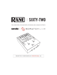
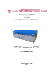
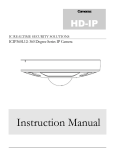
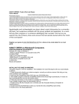
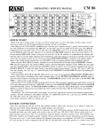
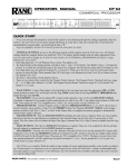
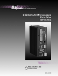
2 1 INPUT 1-2-3 3 PHONO PHONO PHONO LINE LINE LINE LEFT RIGHT +10 +7 -12 +12 -12 +12 +4 -12 +12 +2 GAIN GAIN GAIN 0 -2 AUTO-GAIN -4 -7 L PAN R L PAN R L PAN -10 R -20 MIC ENGAGE 4 CUE EQ 6 2 OFF HI EQ +6 OFF HI EQ +6 OFF HI +6 6 0 10 8 10 MIC 4 2 8 0 MAIN MAIN OL OFF +6 OFF +6 OFF MID MID MID +6 4 6 0 10 2 -12 8 +12 HI OFF +6 OFF +6 OFF BOOTH +6 LOW LOW LOW 4 6 0 10 2 +12 -12 WET DRY LOW DRY DRY WET WET A 6 2 A 8 0 WET AUX OUT SPLIT CUE B CUE MASTER CUE MIC 4 DRY 8 CUE B A POST CUE B A CUE POST B POST AUX IN 0 10 LEVEL CUE RETURN 10 10 10 10 10 10 10 8 8 8 8 8 8 6 6 6 6 6 6 4 4 4 4 4 4 2 2 2 2 2 2 0 0 0 0 0 0 PHONES EQ +12 8 4 0 -4 -8 -12 0 SEND RETURN FlexFX CD1 TRIGGER 1 6 8 10 AUX 4 2 LOW HIGH CD2 TRIGGER 3 A OFF A 0 2 4 6 8 10 10 8 6 4 2 0 B B OFF IMPORTANT SAFETY INSTRUCTIONS 1. Read these instructions. 2. Keep these instructions. 3. Heed all warnings. 4. Follow all instructions. 5. Do not use this apparatus near water. 6. Clean only with a dry cloth. 7. Do not block any ventilation openings. Install in accordance with manufacturer’s instructions. 8. Do not install near any heat sources such as radiators, registers, stoves, or other apparatus (including amplifiers) that produce heat. 9. Do not defeat the safety purpose of the polarized or grounding-type plug. A polarized plug has two blades with one wider than the other. A grounding-type plug has two blades and a third grounding prong. The wide blade or third prong is provided for your safety. If the provided plug does not fit into your outlet, consult an electrician for replacement of the obsolete outlet. 10. Protect the power cord and plug from being walked on or pinched particularly at plugs, convenience receptacles, and the point where it exits from the apparatus. 11. Only use attachments and accessories specified by Rane. 12. Use only with the cart, stand, tripod, bracket, or table specified by the manufacturer, or sold with the apparatus. When a cart is used, use caution when moving the cart/apparatus combination to avoid injury from tip-over. 13. Unplug this apparatus during lightning storms or when unused for long periods of time. 14. Refer all servicing to qualified service personnel. Servicing is required when the apparatus has been damaged in any way, such as power supply cord or plug is damaged, liquid has been spilled or objects have fallen into the apparatus, the apparatus has been exposed to rain or moisture, does not operate normally, or has been dropped. 15. The plug on the power cord is the AC mains disconnect device and must remain readily operable. To completely disconnect this apparatus from the AC mains, disconnect the power supply cord plug from the AC receptacle. 16. This apparatus shall be connected to a mains socket outlet with a protective earthing connection. 17. When permanently connected, an all-pole mains switch with a contact separation of at least 3 mm in each pole shall be incorporated in the electrical installation of the building. 18. If rackmounting, provide adequate ventilation. Equipment may be located above or below this apparatus, but some equipment (like large power amplifiers) may cause an unacceptable amount of hum or may generate too much heat and degrade the performance of this apparatus. 19. This apparatus may be installed in an industry standard equipment rack. Use screws through all mounting holes to provide the best support. WARNING: To reduce the risk of fire or electric shock, do not expose this apparatus to rain or moisture. Apparatus shall not be exposed to dripping or splashing and no objects filled with liquids, such as vases, shall be placed on the apparatus. NOTE: This equipment has been tested and found to comply with the limits for a Class B digital device, pursuant to part 15 of the FCC Rules. These limits are designed to provide reasonable protection against harmful interference in a residential installation. This equipment generates, uses and can radiate radio frequency energy and, if not installed and used in accordance with the instructions, may cause harmful interference to radio communications. However, there is no guarantee that interference will not occur in a particular installation. If this equipment does cause harmful interference to radio or television reception, which can be determined by turning the equipment off and on, the user is encouraged to try to correct the interference by one or more of the following measures: • Reorient or relocate the receiving antenna. • Increase the separation between the equipment and receiver. • Connect the equipment into an outlet on a circuit different from that to which the receiver is connected. • Consult the dealer or an experienced radio/TV technician for help. CAUTION: Changes or modifications not expressly approved by Rane Corporation could void the user's authority to operate the equipment. This Class B digital apparatus complies with Canadian ICES-003. Cet appareil numérique de la classe B est conforme à la norme NMB-003 du Canada. WARNING CAUTION RISK OF ELECTRIC SHOCK DO NOT OPEN To reduce the risk of electrical shock, do not open the unit. No user serviceable parts inside. Refer servicing to qualified service personnel. The symbols shown below are internationally accepted symbols that warn of potential hazards with electrical products. This symbol indicates that a dangerous voltage constituting a risk of electric shock is present within this unit. This symbol indicates that there are important operating and maintenance instructions in the literature accompanying this unit. OPERATORS MANUAL EMPATH DJ MIXER 2 1 PHONO INPUT 1-2-3 3 PHONO LEFT RIGHT PHONO +10 +7 LINE -12 LINE +12 -12 +4 LINE +12 -12 +12 +2 GAIN GAIN GAIN 0 -2 AUTO-GAIN -4 -7 L PAN L R PAN R L PAN -10 R -20 MIC ENGAGE 4 CUE EQ 6 2 OFF HI EQ +6 OFF HI EQ +6 OFF HI +6 6 0 10 8 10 MIC 4 2 8 0 MAIN MAIN OL OFF +6 OFF +6 OFF MID MID MID +6 4 6 0 10 2 -12 8 +12 HI OFF +6 OFF LOW +6 OFF BOOTH +6 LOW LOW 4 6 0 10 2 +12 -12 WET DRY LOW DRY DRY WET WET A 6 2 A 8 0 WET AUX OUT SPLIT CUE B 8 CUE MASTER CUE MIC 4 DRY CUE B A POST CUE B A CUE POST B POST AUX IN 0 10 LEVEL CUE RETURN 10 10 10 10 10 10 10 8 8 8 8 8 8 6 6 6 6 6 6 4 4 4 4 4 4 2 2 2 2 2 2 0 0 0 0 0 0 PHONES EQ +12 8 4 0 -4 -8 -12 0 SEND RETURN FlexFX CD1 TRIGGER 1 6 8 10 AUX 4 2 LOW HIGH CD2 TRIGGER 3 A OFF A 0 2 4 6 8 10 10 8 6 4 2 0 B B OFF Introduction The Empath 10" format mixer offers big-board features and studio quality sound. The mixer is feature packed, yet easy and intuitive to use. How did we pull it off? We asked the master — Grandmaster Flash is responsible for many of the important features and control locations, even the name. “Empath” implies understanding, insight and feeling. When you use the mixer, you’ll get it. The Empath mixer is designed for professional applications: large club, broadcast, competition, remix, live sound. The Empath offers a combination of features, compact size and quality presently unavailable at any price. WEAR PARTS: This product contains the following wear parts subject to the ninety (90) day warranty period described on page Warranty-1: Penny & Giles Fader Assembly (4). Manual-1 Three, fully equipped stereo input channels • • • • • • • 1/2/3 PHONO One Phono and one Line Input for each channel on RCA jacks. ° Be sure to connect each turntable ground to the Phono GND terminal. ° PHONO/LINE source switch selects the Input for each channel. ±12 dB input GAIN trims: ° Adjust for +0 dB on CUE Meter. Left/Right, constant-level PAN controls: ° The loudness stays the same in the room as you Pan left to right. 3-band, full-cut tone controls: ° +6 dB boost to full-cut (off). ° 2nd-order Linkwitz-Riley filter topology. ° Low-Mid crosspoint is 300 Hz. ° Mid-High crosspoint is 4 kHz. EQ engage switch ° Allows “transform” EQ effects. DRY/WET Pan controls: ° Use to split signal between DRY (no effect) and WET (FlexFx loop). ° See FlexFx Loop section for details. A-POST-B Crossfader assignment ° Input channels are assignable to A-side, B-side or Post-Crossfader. ° See Advanced Cue Selection section for automatic “Flash-Cue” operation. LINE -12 +12 GAIN L EQ PAN OFF R +6 HI OFF +6 OFF +6 MID LOW DRY WET A B POST Auto-Gain Switch • Monitors channel-1, -2, and -3 input signals and automatically adjusts the input gain. ° Level is monitored at the Cue point: After PHONO/LINE source selection After GAIN trim After EQ Before the channel Fader • Enable by setting the Input 1-2-3 Auto-Gain switch to the “in” position. ° Green indicator will light. Gain Before ° Auto-Gain is engaged for all three channels or none. AGC LEFT • Target Level: 0 dBu = No gain change. INPUT • Threshold: –16 dBu 1-2-3 ° Minimum level required for Auto-Gain operation. ° If the signal is below –16 dB, the gain holds indefinitely. AUTO-GAIN • Ratio = 3:1 “in” ° 3 dB increase or decrease in input level results in 1 dB increase/decrease in output level. • Turns the gain down at a rate of 32 dB per second. CUE • Turns the gain up at a rate of 5.33 dB per second. “in” • Auto-Gain increase or decrease is monitored by the Cue meter system: ° Set A-CUE-B switch to CUE position. ° Select the desired Cue source. A B SPLIT CUE CUE ° Set SPLIT CUE switch to “IN” position. “in” CUE ° Set CUE/MASTER Pan to center position. ° Set meter CUE/MAIN source switch “IN” to CUE. Any Cue“in” ° Level before Auto-Gain is shown on the left meter. CUE CUE ° Level after Auto-Gain is shown on the right meter. • Set the Input GAIN trim so that normal input levels result in 0 dB on the meter with or without Auto-Gain engaged. 12 AUDIO PRECISION AMPL (dBr) vs AMPL (dBr) 23 MAY 102 13:01:49 12 9 3 Automatic Gain Control (input level increasing) ON Automatic Gain Control (input level decreasing) -18 -18 -15 -12 -9 -6 -3 INPUT LEVEL Manual-2 O 6 U 3 T P 0 U T -3 L -6 E V -9 E L -12 Gain is held below Threshold 0 3 6 +4 +2 0 -2 -4 -7 -10 -20 MAIN MASTER 23 MAY 102 13:01:49 Gain is increased 9 12 Gain is decreased Target -15 -16 dB Threshold -21 -21 +7 AUDIO PRECISION AMPL (dBr) vs AMPL (dBr) -18 -21 -24 -24 +10 9 OFF 6 O U 0 T P -3 U T -6 L -9 E V -12 E -15 L Gain After AGC RIGHT -24 -24 -21 -18 -15 -12 -9 -6 -3 INPUT LEVEL 0 3 6 9 12 Penny & Giles Faders • Most respected, highest quality analog faders available: ° Very high performance, long life and low maintenance. ° Excellent Feel. ° Rated for 2 million cycles. ° Two kinds of fader caps are provided with each mixer for different preferences: ° soft rubber caps for smooth mixing. ° hard plastic caps for fast mixing. • These faders meet the requirements of the most demanding turntablist. • Caution! ° Do not disrespect your Penny & Giles faders. ° Precision parts deserve proper care. ° Read and follow care instructions: ° Do not spray any lubricant or cleaner in the fader; The resistive element is cleaned with warm water and lint free cloth. ° Do not spray lubricant on the slide mechanism — Apply a drop of silicone lubricant directly on rod. ° When in doubt, give Rane a call: 425-355-6000. ° Failure to follow these simple instructions may affect the performance of the pot and will void the warranty. ° See the service and replacement instructions on page Manual-7. CONTOUR • CONTOUR controls are provided for Input-1 and Input-3 faders. 1 CROSSFADER ° Allows any fader response from SLOW smooth fade to FAST cut. • CONTOUR control provided for the Crossfader. ° Allows any response from SLOW smooth blend to FAST cut. SLOW 10 10 8 8 6 6 4 4 2 2 0 0 FAST SLOW 3 FAST SLOW FAST Advanced Cue selection • • Three position switch allows automatic “Flash-Cue” or individual Cue selection: ° Set switch to “A” to Cue all channels assigned to the A-side of the Crossfader. ° Set switch to “B” to Cue all channels assigned to the B-side of the Crossfader. ° Set switch to center position for manual Cue selection using individual Cue switches. Individual Cue switches with green indicators are provided for: ° Input channel-1 A B ° Input channel-2 CUE Input channel-3 ° ° AUX Input 4 6 A B A ° FlexFX RETURN 2 8 CUE CUE POST POST 0 AUX SPLIT CUE A B CUE CUE MASTER B POST • • • 6 0 10 8 10 AUX IN LEVEL CUE PHONES RETURN EQ +12 8 4 0 -4 -8 -12 Headphone Monitor • • • 4 2 Headphone monitor source is decided by two controls: SPLIT CUE switch CUE / MASTER pan control. SPLIT CUE switch “OUT”: CUE / MASTER control pans between stereo Cue selection and stereo Master mix. SPLIT CUE switch “IN”: CUE / MASTER control pans between: mono-Cue in the left channel and mono-Master in the right channel. Headphone LEVEL control determines the loudness. Two-band Headphone EQ: Maximum boost: 12 dB Maximum cut: -12 dB Center frequency: 1 kHz. 3.5 mm and ¼" jacks provided. LOW HIGH Manual-3 Mic Input • • • • • • • Balanced ¼" TRS input (Tip (+), Ring (–), Sleeve (ground) Accepts unbalanced ¼" TS (Tip-Sleeve) plugs. Mic Engage switch turns the Mic on and off without changing the Mic level. ° Green indicator lights when engaged. MIC level control range is Off to +50 dB Overload Indicator: ° Lights 3 dB before clipping. ° Monitors the signal level before and after the HI and LOW tone controls. ° If it lights, turn the MIC level down and/or reduce the tone control boost. 2-band tone control: ° Maximum boost: 12 dB. ° Maximum cut: -12 dB. ° Center frequency: 1 kHz. FlexFX effects loop: ° WET (effect), DRY (no effect) pan control. ° Process mic with any combination of input channels. ° See FlexFX Effects Loop section for details. INPUT 1-2-3 AUTO-GAIN MIC ENGAGE 4 6 0 10 2 8 MIC -12 -12 OL +12 HI +12 LOW AUX Input and Output • • AUX Input: ° Unbalanced RCA jack. ° AUX CUE signal is sent to the cue circuit before the AUX IN level control. ° AUX IN level control range is Off to +10 dB. ° AUX input sums to the Master mix after the Crossfader and FlexFX loop. AUX Output: ° Unbalanced RCA jack. ° AUX OUT control range is Off to +0 dB ° Source is the Master mix: Program 1, 2, 3(pre- or post-effects) plus the Mic (pre- or post-effects) plus the AUX Input. DRY WET MIC 4 6 0 10 2 8 AUX IN CUE AUX Booth Output • • • Balanced ¼" TRS output Level control range is Off to +6 dB Source is the Master mix: Program 1, 2, 3(pre- or post-effects) plus the Mic (pre- or post-effects) plus the AUX Input. 4 6 0 10 2 8 MAIN 4 6 0 10 2 8 BOOTH Main Output • • • Balanced XLR output. Level control range is Off to +6 dB. Source is the Master mix: Program 1, 2, 3(pre- or post-effects) plus the Mic (pre- or post-effects) plus the AUX Input. Manual-4 4 6 0 10 2 8 AUX OUT Level Meters • Level Meters have two modes of operation: ° Stereo Main output ° Cue Monitor. • Meter mode switch set to MAIN “out”: ° Meter displays the level at the Main output, after the Main output LEVEL control. • Meter mode switch set to CUE “in”: ° Meter displays whatever is selected by the Cue and Headphone monitoring circuit. ° This is the same signal heard in the headphones. ° Monitor any combination of the five individual Cue signals -or- A-side auto-cue -or- B-side auto-cue. ° Split Cue metering is the same as split cue monitoring in the headphones: Mono-Cue in the left, Mono-Master in the right. LEFT RIGHT +10 +7 +4 +2 0 -2 -4 -7 -10 -20 CUE MAIN FlexFX Effects Loop Inputs 1, 2, 3 and MIC • Allows the addition of an external stereo effects processor. DRY WET • Individual DRY/WET pan controls for channels 1, 2, 3 and MIC. • Use DRY/WET pan controls simultaneously in any combination. • SEND level control: ° Off to +0 dB. ° Set SEND to prevent overloading the effects processor. ° Many effects devices can't tolerate the high signal levels possible with the Empath. CUE • Unbalanced ¼" Tip/Sleeve SEND jacks. RETURN • Unbalanced ¼" Tip/Sleeve RETURN jacks. • FlexFX RETURN CUE ° FlexFX RETURN CUE is before the RETURN level control. ° Allows Cuing effects before bringing into mix: SEND RETURN Set FlexFX RETURN to minimum. FlexFX Adjust desired DRY/WET pan control to send signal to the effects processor. Set A-CUE-B switch to center CUE position. Engage FlexFX RETURN CUE “in”. Monitor the effect in the headphones. Bring the effect into the master mix by increasing FlexFX RETURN Level • Important reminders when using the FlexFX Return Cue: ° The FlexFX Loop is after the channel Fader and Crossfader. You will hear nothing in the Return Cue if the signal is turned down by the channel Fader. You will hear nothing in the Return Cue if the signal is turned down by the Crossfader ° For a signal to reach the FlexFX Loop: One or more of the four DRY/WET pan controls must be set for some WET. The Send Level must be turned up. ° To send DRY (no effect) signal to the Master mix while you Cue the WET signal: Set the DRY/WET pan control in the middle. If you set it to WET with the FlexFX RETURN down, you will lose the signal in the Master mix. If you set it to DRY, nothing is sent to the FlexFX Loop. ° Setting any DRY/WET Pan control to its center position sends an equal signal to the Master mix and the FlexFX Loop. • RETURN level control: ° Off to +6 dB ° Use in combination with the DRY/WET pan controls to determine how much effect is in the Master mix. ° Increases the signal level of low voltage effects processors to the higher levels possible with the Empath. 10 0 Manual-5 10 10 10 10 10 8 8 8 8 8 8 6 6 6 6 6 6 4 4 4 4 4 4 2 2 2 2 2 2 0 0 0 0 0 0 CD1 TRIGGER 1 10 CD2 TRIGGER A 3 OFF A 0 2 4 6 8 10 10 8 6 4 2 0 B B OFF CD Triggers • The Empath mixer provides two CD triggers: ° CD1 TRIGGER switch determines trigger source 1 —› Input Fader 1 is the source OFF —› No trigger A —› A-side Crossfader is the source ° CD2 TRIGGER switch determines trigger source 3 —› Input Fader 3 is the source OFF —› No trigger B —› B-side Crossfader is the source • Standard CD trigger format ° 3.5 mm ‘mini’ TRS jacks ° Start pulse on Tip. ° Stop pulse on Ring/Sleeve. ° Normally high – Active low. ° Pulse width is 20 ms. ° Start threshold is at –65 dB of control attenuation. ° Stop threshold is at –75 dB of control attenuation. • CD triggers may be used with some external effects processors and drum machines ° See manufacturers specifications for details. Internal switching power supply • • • • • • Plug in virtually anywhere IEC inlet with power switch Universal internal switching power supply 100 to 240 VAC ±10% 50/60 Hz, 20 watts US 120 volt cord provided Note: The internal fuse F1 should be replaced only by qualified service personnel with the same type and rating: (Wickman, type TR5, #372-1100-000, 250 volt, 1.0 amp, time delay). Manual-6 Service Instructions for Penny & Giles X3000 Series Crossfader Introduction Servicing is limited to cleaning, re-lubrication and replacement of some components, such as the slider and track assembly. Periodic maintenance provides a smooth operating feel and extends the life of the fader. Cleaning of the fader is necessary if it is used in dirty or dusty environments or if contaminants have reached inside. The fader must be removed from the panel before servicing. Spare Part Description PGFX3000 Penny & Giles Part No. D460621 Rane Part Number 12206(shown right) Instructions 1. Remove the two screws from the end of the fader where the wires exit, and pull away the end block. Withdraw the dust cover and damping washer. Taking great care remove the slider assembly, ensuring the wiper contacts are not damaged as this affects operation. Cleaning of the slider assembly is possible by gently wiping the wiper contacts and slider bearings using a tissue or cotton bud. If the slider bearings are excessively worn, as seen by excessive slider rocking, a replacement assembly should be fitted. 2. Clean the guide rod, using a tissue or cloth, removing all traces of dirt or contamination. 3. Remove the track by carefully withdrawing from the unit and placing face up on the desk. It may be cleaned with a lint free cloth, rubbing firmly along the track so no debris remains. If necessary, the track can be washed in warm water, wiped gently and then dried thoroughly using a dry cloth. When dry, wipe with a lint free cloth and check for marks along the track. (Note: Lint-free clothes are recommended to avoid dust or fibers from being deposited). If the track appears worn, or if cleaning does not improve operation, replacement may be necessary. 4. Examine the centre channel of the fader body and if dirty, clean using cotton buds. 5. Re-assemble and lubricate the fader as follows: a) Hold the fader body so the end block is to your right, as shown below (the label may be on either side). a) Insert the slider assembly onto the guide rod and into the fader body, with the contacts facing away from you. b) Insert the track into the back of the fader body with the track contacts facing you (to meet the slider contacts). c) Lubricate the guide rod by placing one small drop of silicon oil, using a cocktail stick, either side of the slider assembly. Move the slider from end to end in order to disperse the oil evenly. Carefully wipe away any excess oil using a tissue or cloth. e) Insert the dust cover and damping washer. Hold in place while securing the remaining end block. Be sure track wires exit the bottom of the fader body and are not pinched. 6. Once assembled, move the slider from end to end and ensure operation is smooth. Manual-7 Empath Block Diagram +5 OL MIC BALANCED INPUT OFF +50 dB EQ DRY +12 –12 LOW FlexFX LOOP SEND MIC ENGAGE FlexFX SEND WET HI MIX LEFT LEFT PGM 1 L GAIN (dB) +12 RIAA VCA +6 LINE PGM 1 PHONO BAL LOW MID +6 dB MASTER MIX AUX AUX IN WET OFF PHONO RETURN LEVEL 0 dB DRY EQ AUX INPUT LEVEL 10 dB HI 15 Hz HIGH PASS BOOTH LEVEL PGM 1 AUX OUTPUT LEVEL PGM 1 RIGHT GAIN (dB) -12 +12 EQ LINE PGM 2 RIAA VCA +6 WET OFF PHONO PHONO BAL LOW MID CROSSFADER CONTOUR A/D CROSSFADER A/D DRY HI CROSSFADER A BOOTH OUT +6 dB AUX OUT 0 dB OFF PGM 3 B CH 1 FADER A/D CH 2 FADER A/D DRY CH 3 FADER A/D WET CH 3 CONTOUR CROSSFADER B OFF TIP=START RING=STOP TRIGGER A TRIGGER B PGM 3 L -12 GAIN (dB) +12 EQ LINE PGM 3 VCA +6 OFF PHONO LOW MID HI D/A D/A D/A PGM 3 RIGHT PGM 1 R A/D PGM 2 R A/D PGM 3 R A/D AUTO-GAIN AUTO-GAIN BAL CONTROLLER CROSSFADER ASSIGN RIAA PHONO A CH 1 CONTOUR PGM 2 RIGHT LINE CD TRIGGERS PGM 2 L FADERS LINE MASTER OUT MAIN LEVEL RETURN FlexFX RETURN LINE -12 HOUSE LEFT 0 dB CH 1 A POST B CH 2 A POST B CH 3 A POST B PGM 1, 2, & 3 are assigned to A Cue Sum or B Cue Sum, depending on fader assignment. This allows automatic “Flash” Cueing of A and B sides of the Crossfader. CUE SELECT IN OUT +10 +7 +4 +2 +0 -2 -4 -7 -10 -20 HOUSE LEFT A HOUSE RIGHT A MIX LEFT A MIX LEFT RETURN MIX RIGHT AUX CUE SUM PGM 1 L EQ B CUE SUM B CUE SUM RIGHT –12 CUE MONO MIX RIGHT B B +12 CUE LEFT FLASH-CUE PGM 2 L PGM 3 L METER MODE HOUSE / CUE A CUE SUM PAN LOW HI LEFT 1/4" +16 dB HEADPHONE OUTPUTS LEVEL EQ MIX MONO CUE RIGHT +12 –12 LOW RIGHT 3.5mm +16 dB HI NORMAL / SPLIT CUE ©Rane Corporation 10802 47th Ave. W., Mukilteo WA 98275-5000 USA TEL 425-355-6000 FAX 425-347-7757 WEB www.rane.com Manual-8 All features & specifications subject to change without notice. 106216