1
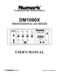
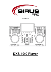
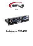
User manual
CDXM-3000
Table of content
1.
Safety instructions ........................................................................................................................... 3
1.1.
FOR SAFE AND EFFICIENT OPERATION ............................................................................ 3
2.
Technical data ................................................................................................................................. 4
3.
Controller function ........................................................................................................................... 5
4.
Mixing Console Function ................................................................................................................. 8
5.
Connection....................................................................................................................................... 9
2 / 10
1. Safety instructions
This device is suitable for indoor use only.
All modifications to the device will void the warranty.
Repairs are to carry out by skilled personnel only.
Use only fuses of the same type and original parts as spare parts.
Protect the unit from rain and humidity to avoid fire and electric shocks.
Make sure to unplug the power supply before opening the housing.
1.1. FOR SAFE AND EFFICIENT OPERATION
Be careful with heat and extreme temperature
Avoid exposing it to direct rays of the sun or near a heating appliance.
Not put it in a temperature bellow 41°F /5°C, or exceeding 95°F /35°C.
Keep away from humidity, water and dust
Do not place the set in a location with high humidity or lots of dust.
Containers with water should not be placed on the set.
Keep away from sources of hum and noise
Such as transformer motor, tuner, TV set and amplifier.
To avoid placing on un-stable location
Select a level and stable location to avoid vibration.
Do not use chemicals or volatile liquids for cleaning
Use a clean dry cloth to wipe off the dust, or a wet soft cloth for stubborn dirt.
If out of work, contact sales agency immediately
Any troubles arose, remove the power plug soon, and contact with an engineer for repairing,
do not open the cabinet by yourself, it might result a danger of electric shock.
Take care with the power cable
Never pull the power cable to remove the plug from the receptacle, be sure to hold the plug.
When not using the device for an extended period of time, be sure to disconnect the plug
from the receptacle.
3 / 10
Important:
Damages caused by the disregard of this user manual are not subject to
warranty. The dealer will not accept liability for any resulting defects or
problems. Make sure the electrical connection is carried out by qualified
personnel. All electrical and mechanical connections have to be carried out
according to the European safety standards.
2. Technical data
Features
Scratch Mode
DSP Brake/Reverse
ID3
Range of adjustments
+/- 12%
Pitch range
+/- 4/8/16%
Connections
2 x USB-A (MP3; FAT32)
2 x 3-IN-1 Card Slot (MP3; FAT32)
1 x asym. XLR/6.3 mm Mic In
1 x 6.3 mm Headphones
2 x Ground Turntables
Line In
2 x asym. RCA
Line Out
2 x asym. RCA
Power supply
~100-240 V, 60/50 Hz
Power consumption
1400 VA
Dimensions
482 x 90 x 80 mm
Weight
6 Kg
4 / 10
3. Controller function
1. JOG & SHUTTLE WHEELS
Search: Touch the dial and rotate it to navigate through the track. Press the jog mode button
and the light is illuminated first.
Pitch: While playing, rotate the dial to adjust the pitch bend.
Cue point: In pause state, rotate the dial to navigate through the track and once you enter a
desired point press the Play/Pause button. Then the CUE button light blinks three times to
show that the point was recorded successfully.
Note: Rotate the dial clockwise is forward, counterclockwise is backward
2. PLAY/PAUSE BUTTON
Each time you press the PLAY/PAUSE button, the operation changes from play to pause or
from pause to play.
3. CUE BUTTON
To define and record a return point from which playback starts again.
4. PITCH BEND + BUTTON
The pitch speeds up when the + button is pressed and returns to the original pitch when it is
released.
5. PITCH BEND – BUTTON
The pitch will slow down while the – button is pressed and returns to the original pitch when it
is released.
6. REPLACEABLE CROSSFADER
Enables clean segues between the two input channels. Hard left selects channel 1. Hard right
selects channel 2. When the crossfader is centered, both assigned channels are live. Use the
crossfader for fast and seamless segues from one selected channel to the other.
7. SCRATCH MODE
When the (10) is illuminated the wheel is in SCRATCH mode, you may press the SCRATCH
button to exit SCRATCH mode.
8. When you enter the JOG work mode the lamp lights up.
5 / 10
9. SCRATCH MODE
When the (10) is illuminated the wheel is in SCRATCH mode, you may press the SCRATCH
button to exit SCRATCH mode
10. When you enter the JOG work mode the lamp lights up.
11. FOLDER/TRACK SEARCH
Allows you to navigate through folders or tracks similarly in either USB or CD mode. When
navigating through a standard CD, turn the rotary to the right to advance the selection or turn
the rotary to the left to decrease the selection.
12. When you enter the SD work mode the lamp lights up.
13. When you enter the USB work mode the lamp lights up.
14. USB PORT
Enables connecting any USB memory stick.
15. 3-IN-1 CARD SLOT
Slot for inserting a 3-IN-1 card. The contacts of the card must point downwards. The unit
cannot read cards with a capacity of more than 4 GB. The unit is not compatible to SDHC
cards and only supports the MP3 format.
16. USB/SD
Select the audio source between USB storage and SD card.
17. PITCH BUTTON
Pitch on/off switch. The adjustment of the pitch potentiometer is available when pitch state is
on and the light is illuminated.
18. INPUT TOGGLE SWITCH
Selects which source will be live to that channel based on what you have connected to the
rear panel input section. In USB 1 or SD 1 position the internal USB 1 or SD 1 units are active.
19. CUE FOR CH1-2
Selects which source will be live to that channel for CH1 & CH2.
20. INPUT TOGGLE SWITCH
Selects which source will be live to that channel based on what you have connected to the
rear panel input section. In USB 2 or SD 2 position the internal USB 2 or SD2 units are active.
21. DISPLAY
LCD Display indicates the Track/Numbers/Time/Remain/Pitch/Continue/Single.
22. IN BUTTON (LOOP SYSTEM)
This button sets the beginning point of the loop and the light is illuminated.
23. OUT BUTTON (LOOP BUTTON)
When you press this button, you set the end point of the seamless loop and you start the loop.
To finish the loop, press this button again.
24. RELOOP BUTTON (LOOP SYSTEM)
This button is used to start the last saved loop. To finish the loop, press this button again.
25. DSP/REVERSE
Push the reverse button to play your track in reverse, push the reverse button again to cancel
this feature.
6 / 10
26. DSP/BRAKE
In play mode push the brake button at first and then push Play/Pause button, the operation
changes slowly from play to pause. Push the Play/Pause button again to cancel this feature.
27. SINGLE
Press this button to switch between the SINGLE and CONTINUE play mode. The selected
mode is indicated on the LCD. In SINGLE mode, after each track, the unit stops the reading.
In CONTINUOUS mode, the unit reads all track and stops.
28. TIME BUTTON
Use this knob to choose the time mode: Elapsed time, remaining time or total.
29. REPEAT BUTTON
Use this button to repeat one track or all the tracks of the CD.
30. ID3
When you press the ID3 button, the names of the songs are shown on the display.
31. PITCH CONTROL
Use this fader to increase or decrease the speed of the track. Slide up to decrease the pitch
and slide down to increase the pitch.
7 / 10
4. Mixing Console Function
32. LED METER
Indicates the master output level
33./41. CH1&CH2 GAIN CONTROL
Adjusts CH1&CH2 level
34./40. HIGH FADER 1-2
Adjust CH1&CH2 equalization of high
35./39. LOW FADER 1-2
Adjust CH1&CH2 equalization of low
36./38. INPUT FADER
Controls individual source levels for CH1-2 in the mix
37. HEADPHONE VOL
Adjust headphone level
42. MIC VOL
Adjust microphone level
43. MASTER VOL
Adjust master level output
8 / 10
44. HEADPHONE JACKS
This is used to connect headphones for audio monitoring.
45. DJ MIC
For plugging in a XLR type microphone.
5. Connection
46. AC CORD
Use this cable to connect the AC mains power to the unit
47. POWER BUTTON
Press the power switch to turn on the unit. To switch the POWER off, press the POWER
switch again.
48. STEREO MAIN OUTPUT
Unbalanced RCA connectors are controlled by the master fader.
49. INPUT
Plug in a line level device such as tape deck or additional CD player here
50. LINE/PHONO INPUT SWITCH
Use this to allow either line level or phono level equipment to be plugged into your channel
inputs. When phono input is selected, your signal is fed directly to the high-quality RIAA phono
preamplifiers. Line level sources will overload the sensitive phono pre-amps and will sound
very bad, so always be sure to toggle the line / phono switch over to line before connecting
line sources.
51. GND
Grounding plug for turntable connection. Always use this connection when using turntables.
Your turntable cable should have a grounding wire.
9 / 10
Importer:
B & K Braun GmbH
Industriestraße 1
D-76307 Karlsbad
www.bkbraun.com
[email protected]
10 / 10