1
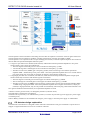
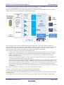
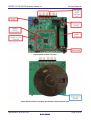
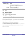
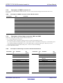
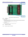
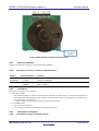
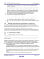
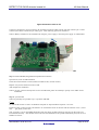
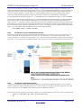
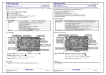
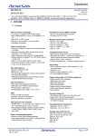
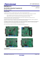
DETECT-IT RL78/I1D detector boards kit Kit User Manual The chemical sensor CO sensor canister is used to detect CO gas at 100ppm +/- 10 ppm and greater. An aerosol such as CO Check ™ or Model HO-CO rev2 test CO gas can be used to simulate an event. In the case of the CO detector, only 2 operational amplifiers are used: they are used to process CO sensor current to voltage and look for CO gas exceeding the pre-determined threshold. Figure CO sensor block diagram The CO chemical sensor is the first element of the analog front end. The CO gas sensor is used as the sensor for concentration of CO gas. It is a CO sensor canister (Figuro TGS5042 CO gas sensor) and it is used to provide a linear output current that is proportional with CO gas concentration. Its specification is 1.2nA-2.4nA per PPM, and the calibrated output value is printed on the canister (for example 1402 indicates 1.402nA/PPM) The CO sensor is connected to 2-stage processing analog front end: 1 stage DC bias: uses single channel (Ch1) of RL78/I1D internal operational amplifier in low power mode at about 2.25µA typical current drain. This stage implements a voltage follower configuration from a resistive divider at VDD/11 (nominally 0.3Volt @ VDD = 3.3V) and provides a low impedance to the CO sensor negative terminal bias point. 1 stage Trans-conductance amplifier: uses single channel (Ch0) of RL78/I1D internal operational amplifier in low power mode at about 2.25µA typical current drain. For the both the DC bias and Trans conductance amplifier configurations, the required frequency response is less than 1Hz and the operational amplifier GBW = 40kHz rating in low power mode is more than adequate. Since the 2 operational amplifier channels together have ~4.5µA typical current drain in low power mode, they can be left on without a huge increase in STOP/standby mode current. As the CO sensor has a relatively long time constant (>10 seconds) to fully react to the CO gas concentration levels, the operational amplifiers need to be left on constantly. So in this CO sensor detector demonstration, only 2 operational amplifiers are used. A buzzer is used to give the alarm, it is managed by the MCU (transistor driver). The push button is used connected, but not used in the CO detector demonstrator. The board can be powered by a 3V lithium battery (CR123). It can also be powered by power supply (E1 power supply or external power). Caution: Battery should never be installed when using E1 power supply or external power supply via CN02/CN01. UM-YDETECT-IT-RL78 V1.10 Page 7 of 57