1
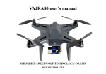
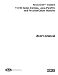
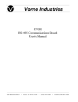
Vorne Industries
2000C Series
Canned Message Display
User's Manual
1445 Industrial Drive • Itasca, IL 60143-1849 • (630) 875-3600 • Telefax (630) 875-3609
2000C Series Canned Message Display
Page 2
2000C SERIES CANNED MESSAGE DISPLAY
Table Of Contents
1.
INTRODUCTION TO THE 2000C DISPLAY
1.1
A Quick Start ....................................................................................... 4
1.2
Features Of The Display ....................................................................... 4
1.3
Programming The Display .................................................................... 4
1.4
Notes On Vacuum Fluorescent Displays ............................................... 4
2.
FEATURES OF THE 2000C DISPLAY
2.1
Fixed, Flashed And Scrolled Messages ................................................. 5
2.2
Chaining Messages Together ................................................................ 5
2.3
Displaying Real Time Variable Data Within A Message ....................... 6
2.4
Queueing Multiple Message Selections ................................................ 6
2.5
Powerup Memory Test ......................................................................... 6
3.
PROGRAMMING THE 2000C DISPLAY
3.1
Placing The Display In The Program Mode .......................................... 7
3.2
The RS232 Programming Port .............................................................. 7
3.3
Programming The Display From An IBM PC Or Compatible ............... 8
3.4
Programming The Display From A Keyboard Or Dumb Terminal ........ 8
4.
INTERFACING THE 2000C DISPLAY TO CONTROLLERS
4.1
Powering The Display ........................................................................ 12
4.2
Selecting A PLC Output Card To Use With The Display .................... 13
4.3
Wiring The Display To Your Controller ............................................. 13
4.4
Wiring Examples ................................................................................ 14
4.5
Placing The Display In The Run Mode ............................................... 17
4.6
Selecting Strobe Or No Strobe Operation ........................................... 17
4.7
Calling Up Messages .......................................................................... 17
4.8
Loading Real Time Variable Data Into A Message ............................. 18
5.
APPENDICES
Appendix A
Appendix B
Appendix C
Mounting Information ........................................................................ 20
2000C Character Set ........................................................................... 21
Message Definition Template ............................................................. 22
2000C Series Canned Message Display
Page 3
1. INTRODUCTION TO THE 2000C DISPLAY
1.1 A Quick Start
If this is your first time working with the Vorne 2000C display and you would like a quick way to see what
the lit display looks like , this section is for you. The quickest way to see a display is to put the unit in the
PROGRAM mode. To accomplish this connect DC ground (terminal one) to the PROGRAM terminal (terminal
four), and apply power to the display (see section 4.1 Powering The Display). The display will light up with the
message:
“EDITING MESSAGE 001”.
1.2 Features Of The Display
The model 2000C canned message display can store up to 250 messages of 20 characters each in an
EEPROM non-volatile memory. Each message can be programmed to be fixed, flashed or scrolled, and to time
out automatically or persist until the next message is called up. In addition messages can be chained together to
allow up to 180 characters (9 messages) to be displayed from a single message address either by scrolling the
entire message or by alternately displaying lines of text. Up to 8 characters of real time variable data can be
inserted per fixed or flashed message and can be inserted anywhere within the 20 available characters. A FIFO
(first in - first out) message queue allows up to 8 messages to be queued in internal memory at any time. Message
callup and variable data loading are handled through the same port minimizing the number of I/O points needed
to interface to the display.
1.3 Programming The Display
The 2000C display is field programmable through its RS232 PROGRAM port. Any keyboard or computer
capable of transmitting the required protocol (RS232 at 300 baud, 8 data bits, no parity and 1 or 2 stop bits) can
be used to program the display. The Vorne Display-Pro software package for IBM personal computers and
compatibles (available at no charge from the factory) makes it very easy to program displays from the PC. The
software also provides hard copies of message files, long term message file storage and easy programming of
additional displays.
On displays powered from 120 VAC or 10-30 VDC, the display sources an auxiliary regulated +5 VDC
output (200 mA maximum) useful for powering keyboards.
1.4 Notes On Vacuum Fluorescent Displays
Vacuum Fluorescent display technology was chosen for this product because of its superior brightness,
viewing angle, and spectral qualities. The natural color emitted by the display tube is a green blue, peaking at
a wavelength of 505 nanometers. The display is filterable to blue, red or yellow by using different labels. If one
of these colors is desirable for your application please consult the factory. The VFD tube has a rated life of 50,000
hours (almost six years of continuous operation). Rated life is said to be reached when the display tube reaches
half brightness. To maximize the life of the display, it is important to avoid keeping the same message fixed
on the display for extended periods (hours). Thus if you wish to have a default message on the display such as
“ALL SYSTEMS GO”, “MACHINE RUNNING” etc, it is suggested that you scroll the message to prevent
imprinting the message on the display phosphors.
2000C Series Canned Message Display
Page 4
2. FEATURES OF THE 2000C DISPLAY
2.1 Fixed, Flashed And Scrolled Messages
Each message when edited can be assigned one of three basic display formats - fixed, flashed or scrolled.
Also assigned is how long (or many times) the message will be displayed. Oftentimes it is convenient to program
a message to display until the next message number is loaded.
Fixed Message - Fixed messages display for a period of time, assignable in two second intervals from 2 to 198
seconds, or alternately until the next message is called up through the parallel input port.
Flashed Message - Flashed messages flash at a fixed rate of approximately 3 times per second for a period of
time assignable in two second intervals from 2 to 198 seconds, or alternately until the next message is called up
through the parallel input port.
Scrolled Message - Scrolled messages scroll across the display (from right to left) at a fixed rate, for a number
of times assignable between 1 and 99 times, or continually scroll until the next message is called up through the
parallel input port. Scrolling is especially useful in combination with chaining messages together, to create
continuous messages of up to 180 characters in length.
2.2 Chaining Messages Together
Any message can be the start of a chain that links together up to 8 additional messages. Chaining is
especially useful to create messages longer than 20 characters (up to 180 character messages are possible with
chaining). These longer messages can be displayed either by scrolling the entire message or by alternately
displaying lines. Chaining is also useful in applications where a common message segment is defined in one
message location and then repeatedly linked to other messages, the overall effect being to reduce the amount of
message memory used. Each message can have its own independent chaining sequence defined, thus 250
independent chains are possible (one for each message). For example, messages 1, 2 and 9 can have the following
chained sequences defined all at the same time.
MESSAGE 001: 001 -> 002 -> 003 -> 004 -> 005 -> 006 -> 007 -> 008 -> 009
MESSAGE 002: 002 -> 004 -> 006 -> 008 -> 001 -> 003 -> 005 -> 007 -> 009
MESSAGE 003: 009 -> 008 -> 007 -> 006 -> 005 -> 004 -> 003 -> 002 -> 001
The first message in any chain determines the attributes of the entire chain; message type (fixed, flashed
or scrolled), message timing and which other messages will be links in the chain. All linked messages just add
more text — they do not change the operation. For example, if the first message in a chain is of the scrolled type,
the entire chain will be scrolled, regardless of how the other messages are formatted. If the first message in a chain
is fixed or flashed, each message in the chain will display fixed or flashed for a duration determined solely by
the first message.
2000C Series Canned Message Display
Page 5
2.3 Displaying Real Time Variable Data Within A Message
Up to 8 real time hexadecimal (0-9 and A-F) variable data characters can be displayed in each and every
one of the 250 messages. The variable data can be loaded whenever the message is displayed, and can be updated
repeatedly as long as the message continues to be displayed. There are some important limitations of variable
data to be noted. Variable data can only be loaded into fixed or flashed messages that are not chained. In other
words variable data cannot be loaded into scrolled messages or chained messages. Also, variable data cannot be
queued, it must be loaded following the message selection, while the message is actually being displayed.
When programming messages, space is reserved for a variable data character by embedding the character
“^” (5E Hex) in the message wherever a variable data character is desired. As an example, if one of the messages
displays production count and rate, with 5 digits of count and 3 digits of rate, the message text would be entered
in the PROGRAM mode as:
“COUNT ^^^^^ RATE ^^^”
The required loading and timing sequences for variable data are discussed in section 4.8 (“Loading Real Time
Variable Data Into A Message”).
2.4 Queueing Multiple Message Selections
If multiple messages are called up within a short period of time, the display will automatically queue up
to eight message numbers in internal memory for subsequent display in a FIFO (first in - first out) basis. Fixed
and flashed messages will be displayed for several seconds and scrolled messages will be displayed once
regardless of what was originally programmed. Thus all queued messages will be processed through, displaying
for a minimum of several seconds until the message queue is empty.
For some applications queueing may not be desirable (for example when the programmable controller is
internally prioritizing or queueing messages, or when it is desired to have the message display always reflect
whichever message number is currently on the parallel input port). A special version of the 2000C operating
software is available with queueing disabled for fixed messages, thus providing immediate display of the most
recently called up message. In this special software scrolled and flashed messages are still subject to queueing.
If this is desirable for your application please consult the factory.
2.5 Powerup Memory Test
Every time a message is edited, the 2000C calculates a checksum of the entire message memory which it
stores in nonvolatile memory. If this stored checksum does not match a newly calculated checksum on powerup
the display will show the message:
“ERROR MEMORY CHECK”
This is an indication that the message memory contents have been corrupted and the unit may need servicing.
The message will automatically disappear after several seconds and the display will allow operation. It is
suggested, however, that the display be reprogrammed and, if the error message persists, returned to the factory
for evaluation.
2000C Series Canned Message Display
Page 6
3. PROGRAMMING THE 2000C DISPLAY
3.1 Placing The Display In The Program Mode
To put the display in the PROGRAM mode connect DC ground (terminal one) to the PROGRAM terminal
(terminal four), and apply power to the display (see section 4.1 Powering The Display). The display will light
up with the prompt
“EDITING MESSAGE 001”
From this prompt, the display is ready to allow editing of the internally stored messages through the RS232
PROGRAM port.
3.2 The RS232 Programming Port
The 2000C display is field programmable through its RS232 PROGRAM port. Any keyboard or computer
capable of transmitting the required protocol (RS232 at 300 baud, 8 data bits, no parity and 1 or 2 stop bits) can
be used to program the display. Since no communication handshaking is required or provided by the display, just
two wires are needed for serial communication. These are the signal ground and transmit data (TXD) from your
keyboard or computer. Most computers and many serial keyboards use either a DB9 or DB25 connector for their
serial port. A DB9 usually has signal ground on pin 5 and transmit data on pin 3. A DB25 usually has signal ground
on pin 7 and transmit data on pin 2. Terminals 1 and 2 on displays powered from 120 VAC or 10-30 VDC source
an auxiliary regulated +5 VDC output (200 mA maximum) which is useful for powering keyboards.
Wire your keyboard or computer to the display as follows:
PROGRAMMING
DC GND
+5V OUT
RS232 IN
PROGRAM
RETURN
RESET
Personal
Computer
Color Display
1
2
3
4
5
6
7
SIGNAL GROUND
Personal
Computer
TRANSMIT DATA
2000C Series Canned Message Display
Page 7
3.3 Programming The Display From An IBM PC Or Compatible
If an IBM personal computer or compatible is available for programming the display, we highly recommend
using the Vorne Display-Pro software package (available at no charge from Vorne). The Vorne Display-Pro utility
provides a complete development environment designed to decrease the time it takes to program and reprogram the
Vorne 2000C series alphanumeric canned message displays.
With the VDP utility the user can create new message files, edit previously saved message files, and
simulate how messages will appear once programmed in the Vorne 2000C display. The program will also print
out hard copies of message files for documentation purposes, provide long term message file storage and provide
easy dumping of message files to one or more displays.
The VDP program is menu driven with pull down menus and extensive online help. Available in both
5 1/4" and 3 1/2" disk formats it requires the following hardware:
• a personal computer running MS-DOS or PC-DOS version 2.00 or later;
• one floppy disk drive (hard disk optional);
• 256K RAM available memory;
• one Asynchronous Communications Adapter (serial port).
Note: The remainder of section 3 pertains to programming the 2000C display from a keyboard or a dumb
terminal, and can be ignored if you areusing the Vorne Display-Pro software to program the display. In the latter
case follow the instructions provided with the VDP software.
3.4 Programming The Display From A Keyboard Or Dumb Terminal
Note: This section pertains to programming the 2000C display from a keyboard or a dumb terminal, and should
be skipped if you are using the Vorne Display-Pro software to program the display.
When working through the menus (described below and flowcharted in Figure 1), several keys have special
uses that are documented below. Experiment - you will soon get an intuitive feel for the editing process.
KEY
“CR”
NAME
Carriage Return
FUNCTION
Accepts the current menu choice.
“SP”
Space Bar
Increments choices within a menu; increments message number whenever that is
a selection.
“ESC”
Escape Key
Return to “EDITING MESSAGE ###” prompt with no action taken. Also used
to bypass message chaining menu, and to return to “DISPLAY TIL NEXT MSG”
prompt in message timing menu.
“0”-“9”
Numeric Keys
Overwrites number at blinking cursor. Valid numbers are in the range from “0”
through “9”.
2000C Series Canned Message Display
Page 8
###
X
is any number between 1 and 250
is any number between 1 and 9
A) Message Selection
Prompt
“EDITING MESSAGE ###”
Description The initial message when entering the PROGRAM mode allows selection of any of the 250 messages
for editing. Any attempt to enter a message number greater than 250 will default to 001.
Keys
“SP” • Increments the message number.
“0”-“9” • Overwrite message number at blinking cursor location.
“CR” • Accepts the message number and goes to next menu (B1).
• Goes to message review menu (F).
“R”
B1) Message Type - Fixed
Prompt
“MESSAGE ### FIXED”
Description Selects the message type to be fixed.
Keys
“CR” • Accepts the message type as fixed. Go to (C1).
“SP” • Increments menu choice to (B2).
B2) Message Type - Flashed
Prompt
“MESSAGE ### FLASHED”
Description Selects the message type to be flashed.
Keys
“CR” • Accepts the message type as flashed. Go to (C1).
“SP” • Increments menu choice to (B3).
B3) Message Type - Scrolled
Prompt
“MESSAGE ### SCROLLED”
Description Selects the message type to be scrolled.
Keys
“CR” • Accepts the message type as scrolled. Go to (C1).
“SP” • Wraps the menu choice back to (B1).
C1) Message Timing - Til Next Message
Prompt
“DISPLAY TIL NEXT MSG”
Description Instead of allowing the message to time out, when this menu option is selected the message remains
on the display until another message is called up.
“SP” • Increments the menu choice to (C2).
Keys
“CR” • Accepts the current choice and goes to next menu (D).
2000C Series Canned Message Display
Page 9
C2) Message Timing - Fixed Time
“DISPLAY MSG XX TIMES”
Prompt
Description Selects the number of times a message is to be displayed. Is selectable in single number increments
from 01 to 99 times. For fixed or flashed messages each time increment represents approximately
two seconds. Thus the message can be timed between 2 and 198 seconds. For a scrolled message
the times designation represents how many times the message will scroll across the display.
“SP” • Increments the message time.
Keys
“ESC” • Returns the prompt to (C1).
“CR” • Accepts the selected message time. Go to (D).
“0”-“9” • Overwrites message time at blinking cursor location.
D) Message Chaining
Prompt
“CHAINLINK X MSG ###”where X represents current chain link and can range from 1 to 8.
Description Allows linking up to eight additional messages to currently edited message.
Keys
“ESC” • Skips chaining and goes directly to message text (E).
“SP” • Increments message number.
“0”-“9” • Overwrites message number at blinking cursor location.
“CR” • If ### is 000 (no message number entered), or if X is 8 (last chain link available) go
to message text (E), otherwise, accepts current chain link message data and increments chain link number.
E) Message Text
When unit is factory shipped, each message location has preset text “MESSAGE XXX BUFFER
!”. Otherwise what appears is the currently stored message text.
Description Loads current message text from nonvolatile memory and allows editing.
Keys
The following edit keys are valid. All other keys are literal in nature, both upper and lower case.
Note that position 1 refers to the leftmost character position and position 20 refers to the rightmost
character position when viewing the display.
“BS” • Backspace key moves cursor back one character without deletion. If at position 1,
the cursor will wrap to position 20.
“LF” • Linefeed key moves cursor forward one character without deletion. If at position 20,
the cursor will wrap to position 1.
“DEL” • Delete key deletes current character and moves cursor back one character. If at
position 1, the cursor will wrap to position 20.
“SP” • Space bar deletes current character and moves cursor forward one character. If at
position 20 the cursor will wrap to position 1.
“^”
• Up-Arrow (also called Carat sign) is used to reserve a variable data position. While
in the PROGRAM mode a “^” will be displayed once it has been entered into a
message. When in the RUN mode blanks will be displayed until variable data is
loaded.
“ESC” • Saves message text and all attributes, recalculates a memory checksum and goes to
message selection prompt (A) for next message (message number is automatically
“CR”
incremented). It is important to note that no message attributes are stored in
nonvolatile memory until the “E SC” or “CR ” key is entered in the message text
menu.
Prompt
2000C Series Canned Message Display
Page 10
F) Message Review
“REVIEW MESSAGE ###”
Prompt
Description Selects message for review, as if it were called up in RUN mode.
• Increments message number.
“SP”
Keys
• Overwrites message number at blinking cursor location.
“0”-“9”
• Will display message selected as if it were called up in the RUN mode.
“CR”
ANY KEY • While the message is reviewing, any key will terminate the message review and
go back to message selection prompt (A) with the reviewed message selected for
editing.
Note: See Figure 1 below for a graphic flowchart of the entire editing process.
Figure 1 - Graphic Flowchart Of Editing Process
EDITING MESSAGE ###
A) MESSAGE SELECTION
"CR"
"SP"
B) MESSAGE TYPE
MESSAGE ### FIXED
"SP"
"CR"
MESSAGE ### FLASHED
"SP"
MESSAGE ### SCROLLED
"CR"
"CR"
"CR"
DISPLAY TIL NEXT MSG
"SP"
"ESC"
DISPLAY MSG 01 TIME
"CR"
"SP"
C) MESSAGE TIMING
"ESC"
"SP"
DISPLAY MSG 02 TIMES
"CR"
DISPLAY MSG 99 TIMES
"CR"
CHAINLINK 1 MSG ###
"ESC"
"CR"
D) MESSAGE CHAINING
CHAINLINK 2 MSG ###
CHAINLINK 8 MSG ###
"ESC"
"ESC"
"CR"
E) MESSAGE TEXT
MESSAGE XXX BUFFER!
Use Text
Editing Keys
"ESC" or "CR"
A) MESSAGE SELECTION
EDITING MESSAGE ###+1
"R" or "r"
F) MESSAGE REVIEW
2000C Series Canned Message Display
REVIEW MESSAGE ### + 1
Page 11
4. INTERFACING THE 2000C DISPLAY TO CONTROLLERS
4.1 Powering The Display
The chart below outlines the operating and inrush power requirements of the three different size models
of the 2000C display.
MODEL
2005C
2009C
2015C
SIZE
5 mm (.2")
9 mm (.35")
15 mm (.59")
OPERATING POWER
2.3 VA
3.6 VA
6.8 VA
INRUSH POWER
X.X VA
X.X VA
X.X VA
Power Connections For Displays With Housing Option C (Panel Mount Case) - Power connections are made
to a separate three terminal power connector (marked A, B, and C). Power is wired into terminals A and B as
shown below. Terminal C is used to provide earth ground to the enclosure. It is highly recommended that earth
ground be wired to terminal C as this will provide a safety ground to the enclosure as well as a return path for
external electrical noise disturbances.
OPERATING VOLTAGE OPTION 120
120 Volt AC ± 15%
EARTH GND
DC GND IN
10-30 VDC IN
EARTH GND
DC GND IN
5V DC IN
EARTH GND
POWER IN
120 VAC
POWER IN
OPERATING VOLTAGE OPTION 5
5 Volt DC ± 5% (Regulated)
120 VAC
POWER IN
OPERATING VOLTAGE OPTION 24
10 - 30 Volt DC
A
B
C
A
B
C
A
B
C
Power Connections For Displays With Housing Option B (Bezel Mount) Or O (No Housing) - Power
connections are made to the first two terminals of the top eight terminal connector. The power supplied must be a
very clean, well regulated 5 Volts DC (± 5%).
1
DC GND
IN
2000C Series Canned Message Display
2
5V DC
IN
Page 12
4.2 Selecting A PLC Output Card To Use With The Display
The RETURN, RESET, VAR DATA, STROBE and D0-D7 inputs are designed to interface with
programmable controllers. For displays ordered with housing option C (panel mount case) input options L and H
are available; for displays ordered with housing options B (bezel mount) or O (no housing) the input goes directly
into a CMOS gate with characteristics outlined below under CMOS.
L Input Specifications - For displays in panel mount case only.
Use input option L with TTL, contact or open collector output cards.
Input Voltage Range
•3.5 to 9 Volt DC Sink or Source
Input Loading
•680 ohm
Leakage Accepted
•Up to 2mA
Logic 0
•1.5 Volts maximum
Logic 1
•3.5 Volts minimum
H Input Specifications - For displays in panel mount case only.
Use input option H with 12, 15 or 24 volt DC output cards.
Input Voltage Range
•9 to 30 Volt DC Sink or Source
Input Loading
•3.3K ohm
Leakage Accepted
•Up to 2mA
Logic 0
•6.6 Volts maximum
Logic 1
•9.0 Volts minimum
CMOS Input Specifications - For displays with bezel mount or no housing only.
Use CMOS input option with TTL, contact or open collector output cards.
Input Voltage Range
•5 Volt DC Sink only
Input Loading
•12K Ohm pullup to 5 Volts
Leakage Accepted
•
Logic 0
•1.5 Volts maximum
Logic 1
•3.5 Volts minimum
4.3 Wiring The Display To Your Controller
This section provides an overview of the inputs designed to interface with programmable controllers
(terminals 5 to 16). These are graphically shown and described below.
Panel Mount Units
Bezel or No Housing Units
Top
RESET
VAR. DATA
STROBE
D0
D1
D2
D3
D4
D5
D6
D7
PROGRAM
N.C.
RESET
VAR. DATA
STROBE
D0
D1
D2
D3
D4
D5
D6
D7
PROGRAMMABLE CONTROL
RETURN
OG. PROG. CONTROL
PROGRAM
PROGRAMMABLE CONTROL
Bottom
4
5
6
7
8
9
10
11
12
13
14
15
16
4
5
6
7
8
9
10
11
12
13
14
15
16
2000C Series Canned Message Display
Page 13
Return (Terminal 5) - Units supplied in a panel mount case can be used with both sink and source output cards,
depending on how the return line is wired. The sink I/O is also known as active low since its on state is ground,
whereas the source I/O is known as active high since its on state is positive DC.
For sink I/O wire the 2000C return line to the plus side of your output card supply. This provides a passive
pullup for all inputs listed in this section. For source I/O wire the 2000C return line to the ground side of your output
card supply. This provides a passive pulldown for all inputs listed in this section. In all cases make sure to wire the
DC ground of the 2000C to the DC ground of your output card supply.
Units supplied with a bezel mount or no housing do not have a return line connection. These displays can only
be used in the sink (active low) configuration. All the inputs are passively pulled up through a 12K Ohm resistor to
5 Volts DC. Wiring examples are shown in section 4.4.
Reset (Terminal 6) - When brought active this terminal will reset the unit to a condition similar to powerup
(display blank, scanning input port, message queue empty). The reset can be used to clear messages from the
display as well as empty the message queues - however no data can be loaded into the display for 100 milliseconds
after a reset.
Var. Data (Terminal 7) - Since the same 8 bit RUN port (D0-D7) is used to both call up messages and to load
real time variable data, the VAR DATA terminal is used to differentiate between the two operations. If the terminal
is held active, any data entered through the RUN port is interpreted as variable data. When not active (or left
floating) any data entered through the RUN port is interpreted as a call for a message. If variable data will not be
used this terminal should be left unconnected.
Strobe / D0-D7 (Terminal 8 to 16) - D0 through D7 and the strobe line make up the RUN port used to both call
up messages and to load real time variable data. Messages are called up using simple binary coding to represent
message numbers. Variable data is loaded one character at a time, using the D0 - D6 port lines to simultaneously
load the binary representation of the character and the position of the variable data character within the message.
When the strobe line is brought active the information on the RUN port (D0-D7) is loaded into the display,
and the corresponding message or variable data is displayed. For applications where variable data is not used the
strobe is optional (see Section 4.6 Selecting Strobe Or No Strobe Operation). For timing requirements and loading
sequences, see Section 4.7 Calling Up Messages and Section 4.8 Loading Real Time Variable Data Into A
Message.
4.4 Wiring Examples
On the next two pages are a variety of examples designed to show proper wiring between the PLC and the
2000C display. Please note that the output card power supply must be compatible with the 2000C input option
ordered (input option L requires 3.5-9 Volt I/O, input option H 9-30 Volt I/O, input option CMOS requires 5 Volt
I/O).
2000C Series Canned Message Display
Page 14
Housing Option “C” (Panel Mount Case)
Wiring Examples
5-30 VOLT DC SOURCE
OUTPUT CARD
5-30 VOLT DC SINK
OUTPUT CARD
5-30 VOLT DC
USERS
SUPPLY
5-30 VOLT DC
USERS
SUPPLY
+
+
-
CONTACT
OUTPUT CARD
5-30 VOLT DC
USERS
SUPPLY
+
-
-
+V
1) DC GND
+V
1) DC GND
1) DC GND
GND
2) +5V OUT
GND
2) +5V OUT
2) +5V OUT
3) SERIAL IN
3) SERIAL IN
3) SERIAL IN
4) PROG
4) PROG
4) PROG
5) RETURN
5) RETURN
5) RETURN
OUT 11
6) RESET
OUT 11
6) RESET
6) RESET
OUT 10
7) VAR DATA
OUT 10
7) VAR DATA
7) VAR DATA
OUT 9
8) STROBE
OUT 9
8) STROBE
8) STROBE
OUT 1
9) D0
OUT 1
9) D0
9) D0
OUT 2
10) D1
OUT 2
10) D1
10) D1
OUT 3
11) D2
OUT 3
11) D2
11) D2
OUT 4
12) D3
OUT 4
12) D3
12) D3
OUT 5
13) D4
OUT 5
13) D4
13) D4
OUT 6
14) D5
OUT 6
14) D5
14) D5
OUT 7
15) D6
OUT 7
15) D6
15) D6
OUT 8
16) D7
OUT 8
16) D7
16) D7
PROGRAMMABLE
CONTROLLER
VORNE
DISPLAY
PROGRAMMABLE
CONTROLLER
VORNE
DISPLAY
1) Tie external supply DC ground
to Vorne DC ground.
1) Tie external supply DC ground
to Vorne DC ground.
2) Tie external supply DC ground to
Vorne Return terminal.
2) Tie external supply +V to Vorne
Return terminal.
3) Connect source outputs to Vorne
inputs.
3) Connect sink outputs to Vorne
inputs.
2000C Series Canned Message Display
CONTACT
OUTPUTS
VORNE
DISPLAY
1) Tie external supply DC ground
to Vorne DC ground and to
common of switches.
2) Tie external supply +V to Vorne
Return terminal.
3) Connect contact outputs to Vorne
inputs.
Page 15
Housing Option “B” (Bezel Mount) Or “O” (No Housing)
Wiring Examples
TTL
OUTPUT CARD
CONTACT
OUTPUT CARD
5 VOLT DC
USERS
SUPPLY
+
+V
GND
-
1) DC GND
1) DC GND
2) +5V IN
2) +5V IN
3) SERIAL IN
3) SERIAL IN
TOP
TERMINAL
STRIP
4) PROG
5) N.C.
4) PROG
5) N.C.
OUT 11
6) RESET
OUT 10
7) VAR DATA
6) RESET
7) VAR DATA
OUT 9
8) STROBE
8) STROBE
OUT 1
1) D0
1) D0
OUT 2
2) D1
2) D1
OUT 3
3) D2
3) D2
OUT 4
4) D3
OUT 5
5) D4
OUT 6
6) D5
6) D5
OUT 7
7) D6
7) D6
OUT 8
8) D7
8) D7
PROGRAMMABLE
CONTROLLER
VORNE
DISPLAY
BOTTOM
TERMINAL
STRIP
4) D3
BOTTOM
TERMINAL
STRIP
5) D4
CONTACT
OUTPUTS
VORNE
DISPLAY
1) Tie external supply DC ground to
Vorne DC ground.
1) Tie Vorne DC ground to common of
switches.
2) Connect TTL outputs to Vorne
inputs.
2) Connect contact outputs to Vorne
inputs.
2000C Series Canned Message Display
TOP
TERMINAL
STRIP
Page 16
4.5 Placing The Display In The Run Mode
When the PROGRAM terminal (terminal 4) is left unconnected the canned message display goes
automatically into the RUN mode. Upon first entering the RUN mode the display will blank and begin scanning the
RUN input port for data. This data can include calling up messages or loading real time variable data into a
displayed message.
4.6 Selecting Strobe Or No Strobe Operation
Although a strobe input is provided as part of the RUN port, for some applications it is not necessary to use
the strobe when calling up messages from the PLC. These are applications where variable data will not be used and
where the PLC outputs are guaranteed to stably change states within the display input debounce time of 5
milliseconds. In such applications it is possible to permanently tie the strobe to the active position so in effect the
display will be in a constant strobe mode and will take in whatever message number is present at the RUN port for
at least 10 milliseconds. The advantages of not using the strobe are easier programming of the PLC and requiring
one less output to operate the display.
4.7 Calling Up Messages
Messages are called up through the RUN input port by simply loading the address in binary, where input D7
is the MSB (most significant bit) and input D0 is the LSB (least significant bit). Some examples of message callups
are listed in the table below.
INPUT
D7 D6 D5 D4 D3 D2 D1 D0
BINARY VALUE
128 64 32 16
8
4
2
1
NO MESSAGE (0)
0
0
0
0
0
0
0
0
MESSAGE 1
0
0
0
0
0
0
0
1
MESSAGE 2
0
0
0
0
0
0
1
0
MESSAGE 3
0
0
0
0
0
0
1
1
MESSAGE 27
0
0
0
1
1
0
1
1
MESSAGE 250
1
1
1
1
1
0
1
0
NO MESSAGE (251)
1
1
1
1
1
0
1
1
NO MESSAGE (255)
1
1
1
1
1
1
1
1
Note: In the above chart 1 refers to the active or on I/O state. For source I/O this is positive DC, for sink I/O this
is ground. 0 refers to the inactive or off I/O state.
To confirm the message apply a strobe pulse of at least 10 millisecond duration to the STROBE input
(terminal 8). The data must be valid for the complete duration of the strobe pulse. After a 10 ms strobe pulse is
received the canned message display will display the message as it was entered and formatted in the PROGRAM
mode. For no strobe operation strap the strobe terminal to the active position (see section 4.6 Selecting Strobe Or
No Strobe Operation). Message numbers must still be present on the D0-D7 port for at least 10 mS duration to be
valid. Below is a timing diagram which shows proper timing requirements for calling up messages when using the
strobe.
2000C Series Canned Message Display
Page 17
Timing Diagram Calling Up Messages (With Strobe)
TON
STROBE
TSETUP
THOLD
TON
TSETUP
THOLD
D0 - D7
10ms
0ms
0ms
4.8 Loading Real Time Variable Data Into A Message
If a message has been programmed for variable data in the PROGRAM mode, the canned message display
will initially display the variable data positions as blanks when the message is called up in the RUN mode. This
section explains how to properly load variable data into the blank positions. Recall that variable data can only be
loaded into fixed or flashed messages that are not chained. Also variable data cannot be queued, in other words it
must be loaded following the message callup, while the message is actually being displayed. Variable data can be
updated repeatedly as long as the message continues to be displayed.
Since the same input port is used to both call up messages and load real time variable data, the VAR DATA
terminal (terminal 7) is used to differentiate between the two operations. Whenever variable data is being loaded
this terminal must be held active. Once the variable data terminal is released (not held active), any new data strobed
in will be interpreted as a message callup.
Variable data is loaded one character at a time, using the D0-D6 port lines to simultaneously load the binary
representation of the character and the position (address) of the variable data character within the message. Each
variable data character must be individually strobed into the unit while a valid character and address are applied to
the data port. The table below lists the input port assignment used when loading variable data.
Below is an example of loading variable data into the message:
Variable Data Port Assignments
INPUT
DATA TYPE
BIT
D7
-
-
BINARY VALUE
-
D6
ADDRESS
MSB
4
D5
ADDRESS
B2
2
D4
ADDRESS
LSB
1
D3
CHARACTER
MSB
8
D2
CHARACTER
B3
4
D1
CHARACTER
B2
2
D0
CHARACTER
LSB
1
“COUNT 89023 RATE 264”
The eight address positions are assigned from right to left. Assigning addresses to the above message:
2000C Series Canned Message Display
Page 18
"COUNT 89023 RATE 264"
ADDRESS
0
1
2
3
4
5
6
7
The order in which the characters are loaded is optional. Each character loaded will immediately be
displayed. In the above example:
CHARACTER ADDRESS
CHARACTER DATA
ADDRESS
DATA
D6
D5
D4
D3
D2
D1
D0
0
"4"
0
0
0
0
1
0
0
1
"6"
0
0
1
0
1
1
0
2
"2"
0
1
0
0
0
1
0
3
"3"
0
1
1
0
0
1
1
4
"2"
1
0
0
0
0
1
0
5
"0"
1
0
1
0
0
0
0
6
"9"
1
1
0
1
0
0
1
7
"8"
1
1
1
1
0
0
0
Note: In the above chart 1 refers to the active or on I/O state. For source I/O this is positive DC, for sink I/O this
is ground. 0 refers to the inactive or off I/O state.
Timing Diagram - Loading 2 Characters Of Variable Data
VAR DATA
TSETUP
THOLD
TON
STROBE
THOLD
TSETUP
TON
TSETUP
THOLD
D0 - D6
Character 1
2000C Series Canned Message Display
10ms
0ms
0ms
Character 2
Page 19
Appendix A - Mounting Information
Housing Option "C" (Panel Mount Case)
The fully enclosed panel mount unit can be mounted through the front of a panel cutout and fastened to the panel with two side clips (provided).
An optional gasket provides front panel Nema 12 sealing.
FRONT
(DISPLAY)
REAR
(TERMINAL BLOCK)
PANEL CUTOUT
S
R
T
V
U
Housing Option "B" (Bezel Mount)
The bezel with attached display and logic boards can be mounted through the front of a panel and fastened to the panel with four integral studs.
BEZEL
DISPLAY TUBE
TERMINAL BLOCKS
U
PANEL CUTOUT
B+.1
T
A+.1
C
D
(4) 6-32 studs centered and 0.15 from bezel edge.
Mounting studs of bezel fit through clearance holes drilled in panel.
Housing Option "O" (No Housing)
The display and logic board can be mounted to the rear of a panel by using the circuit board mounting holes (6-32 clearance holes) provided on
each side of the display tube.
DISPLAY TUBE
TERMINAL BLOCKS
G
H
B
H
J
F
E
C
D
A
Model
Character
Height
A
B
C
D
E
F
G
H
J
R
S
T
MODEL 2005
.20
6.3
2.1
0.5
1.6
6.0
1.3
0.9
1.1
5.4
6.9
2.5
MODEL 2009
.35
9.1
2.4
0.6
1.6
8.7
1.3
1.1
1.4
8.2
9.7
2.8
MODEL 2015
.59
12.7
2.5
0.7
1.6
12.3
1.3
1.3
1.5
11.7
13.3
2.9
U
V
2.8
7.2
4.0
3.1
10.0
4.6
3.2
13.6
4.6
Note: All mounting dimensions are in inches.
2000C Series Canned Message Display
Page 20
Appendix B - 2000C Character Set
00h
01h
02h
03h
04h
05h
06h
07h
08h
09h
0Ah
0Bh
0Ch
0Dh
0Eh
0Fh
10h
11h
12h
13h
14h
15h
16h
17h
18h
19h
1Ah
1Bh
1Ch
1Dh
1Eh
1Fh
20h
21h
22h
23h
24h
25h
26h
27h
28h
29h
2Ah
2Bh
2Ch
2Dh
2Eh
2Fh
30h
31h
32h
33h
34h
35h
36h
37h
38h
39h
3Ah
3Bh
3Ch
3Dh
3Eh
3Fh
40h
41h
42h
43h
44h
45h
46h
47h
48h
49h
4Ah
4Bh
4Ch
4Dh
4Eh
4Fh
50h
51h
52h
53h
54h
55h
56h
57h
58h
59h
5Ah
5Bh
5Ch
5Dh
5Eh
5Fh
60h
61h
62h
63h
64h
65h
66h
67h
68h
69h
6Ah
6Bh
6Ch
6Dh
6Eh
6Fh
70h
71h
72h
73h
74h
75h
76h
77h
78h
79h
7Ah
7Bh
7Ch
7Dh
7Eh
7Fh
2000C Series Canned Message Display
Page 21
Appendix C - Message Definition Template
Use the chart below to help format your messages. Photocopy as desired.
MSG.
#
(1-250) 1
FIXED
FLASHED TIME
10 11 12 13 14 15 16 17 18 19 20 SCROLLED 0-99
MESSAGE TEXT
2
3
4
5
6
7
8
9
2000C Series Canned Message Display
CHAINING SEQUENCE
1
2
3
4
5
6
7
8
Page 22
2000C Series Canned Message Display
Page 23
Vorne Industries Incorporated
1445 Industrial Drive
Itasca, IL 60143-1849
Phone: (630) 875-3600
Fax: (630) 875-3609
P0030R04