1
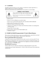
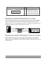
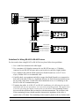
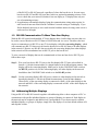
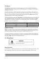
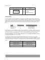
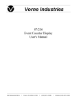
Vorne Industries
87/001
RS-485 Communications Board
User's Manual
1445 Industrial Drive
• Itasca, IL 60143-1849
• (630) 875-3600
• Telefax (630) 875-3609
1.1 Installation . . . . . . . . . . . . . . . . . . . . . . . . . . . . . . . . . . . . . . . . . . . . . . . . . . . . . . . . . . . . . . . . . 2
1.2 RS-422 Or RS-485 Communication To One Or More Displays . . . . . . . . . . . . . . . . 2
Selecting RS-422/RS-485 Communication . . . . . . . . . . . . . . . . . . . . . . . . . . . . . . . . . . . . . . . . . . . . . 2
RS-422/RS-485 Connectors . . . . . . . . . . . . . . . . . . . . . . . . . . . . . . . . . . . . . . . . . . . . . . . . . . . . . . . . . . . 2
Wiring Diagram For An RS-422 Or RS-485 Host Device To One Display . . . . . . . . . . . . . . . 3
Wiring Diagram For An RS-422 Or RS-485 Host Device To More Than One Display . . . . 3
Guidelines For Wiring RS-422 Or RS-485 Devices . . . . . . . . . . . . . . . . . . . . . . . . . . . . . . . . . . . . . 4
1.3 RS-232 Communication To More Than One Display . . . . . . . . . . . . . . . . . . . . . . . . . . 5
1.4 Addressing Multiple Displays . . . . . . . . . . . . . . . . . . . . . . . . . . . . . . . . . . . . . . . . . . . . . . . . 5
Unit Address . . . . . . . . . . . . . . . . . . . . . . . . . . . . . . . . . . . . . . . . . . . . . . . . . . . . . . . . . . . . . . . . . . . . . . . . . . . 6
Member of Group(s) . . . . . . . . . . . . . . . . . . . . . . . . . . . . . . . . . . . . . . . . . . . . . . . . . . . . . . . . . . . . . . . . . . . 6
1.5 Relay Output . . . . . . . . . . . . . . . . . . . . . . . . . . . . . . . . . . . . . . . . . . . . . . . . . . . . . . . . . . . . . . . 6
Relay Connectors . . . . . . . . . . . . . . . . . . . . . . . . . . . . . . . . . . . . . . . . . . . . . . . . . . . . . . . . . . . . . . . . . . . . . . 6
Activate Relay . . . . . . . . . . . . . . . . . . . . . . . . . . . . . . . . . . . . . . . . . . . . . . . . . . . . . . . . . . . . . . . . . . . . . . . . . 7
Notice Of Disclaimer
While the information in this manual has been carefully reviewed for accuracy, Vorne
Industries, Inc. assumes no liability for any errors, or omissions in the information. Vorne
Industries also reserves the right to make changes without further notice to any products
described in this manual.
87 Series RS-485 Communications Board Users Manual
1
1.1
Installation
The RS485 option board allows 87 series displays to communicate serially using RS-485. In
addition a SPDT relay is provided for annunciation.
The RS-485 add-on board can be installed thru the access plate of a 87 series display.
WARNING - SHOCK HAZARD
Always completely disconnect power from the display before
opening the user access plate. Do not reapply power to the
display until the access plate has been reinstalled and
securely closed.
1. Remove power.
2. Remove six screws holding the access plate in place.
3. Remove the 14 position shunt plugged into the socket labeled OPTION BOARD.
4. Slide the RS-485 board thru the access plate.
5. Slide the board into the bottom most card slot.
6. Align the two mounting posts attached to the RS-485 board with the two mounting holes
on the logic board.
7. Snap the RS-485 board in place.
8. Plug the ribbon cable into the OPTION BOARD socket.
9. Installation complete!
1.2
RS-422 Or RS-485 Communication To One Or More Displays
This section provides the information necessary to successfully interface a host RS-422 or RS-485
port to one or more 87 display equipped with the RS-485 Add on board.
Selecting RS-422/RS-485 Communication
A printed circuit board mounted COM PORT slide switch, is used to select between RS-232 and
RS-422/RS-485 communication. This switch is located on the plug in communication board, next
to P4 (COM PORT terminal strip). To enable the 87 series display to receive data via the RS-485
port, set this switch to the RS-485 position.
RS-422/RS-485 Connectors
The RS-422/RS-485 port is fully opto-isolated and is available through the five pins of the
communication port terminal strip (marked P4). The RS-422/RS-485 portion of this terminal strip
is shown below.
2
87 Series RS-485 Communications Board Users Manual
5 Pin RS-485 Terminal Strip (P4)
Pins 1 to 5
Pin
RS-485 Terminal Strip
1
2
3
4
5
Function
1
Isolated Communications Ground
2
RS-422/RS-485 Transmit Data (TxD)+
3
RS-422/RS-485 Transmit Data (TxD)-
4
RS-422/RS-485 Receive Data (RxD)+
5
RS-422/RS-485 Receive Data (RxD)-
Wiring Diagram For An RS-422 Or RS-485 Host Device To One Display
Below is a diagram which shows how to wire an RS-422 (or RS-485) host device to one display.
Please refer to the Guidelines For Wiring RS-422 Or RS-485 Devices section below for important
wiring recommendations, and take special note of the four terminating resistors shown in the
diagram below. For one way communication from the host to the display, the transmit data (TxD)
lines from the display (pins 2 and 3) do not need to be connected.
PLC
Signal GROUND
RS-422 Receive Data (RxD) +
Isolated GROUND
1
RS-422 Transmit Data (TxD) + 2
RS-422 Receive Data(RxD) -
RS-422 Transmit Data (TxD) - 3
RS-422 Transmit Data (TxD) +
RS-422 Receive Data (RxD) + 4
RS-422 Transmit Data (TxD) -
RS-422 Receive Data (RxD) - 5
HOST DEVICE
87 SERIES DISPLAY
Wiring Diagram For An RS-422 Or RS-485 Host Device To More Than One Display
Below is a diagram which shows how to wire an RS-422 (or RS-485) host device to multiple
displays. Please refer to the Guidelines For Wiring RS-422 Or RS-485 Devices section below for
important wiring recommendations, and take special note of the four terminating resistors shown in
the diagram below.
87 Series RS-485 Communications Board Users Manual
3
PLC
Signal GROUND
Isolated GROUND
1
RS-422 Receive Data (RxD) +
RS-422 Transmit Data (TxD) +
2
RS-422 Receive Data(RxD) -
RS-422 Transmit Data (TxD) -
3
RS-422 Transmit Data (TxD) +
RS-422 Receive Data (RxD) +
4
RS-422 Transmit Data (TxD) -
RS-422 Receive Data (RxD) -
5
1ST 87 SERIES DISPLAY
HOST DEVICE
Isolated GROUND
1
RS-422 Transmit Data (TxD) +
2
RS-422 Transmit Data (TxD) -
3
RS-422 Receive Data (RxD) +
4
RS-422 Receive Data (RxD) -
5
2ND 87 SERIES DISPLAY
Isolated GROUND
1
RS-422 Transmit Data (TxD) +
2
RS-422 Transmit Data (TxD) -
3
RS-422 Receive Data (RxD) +
4
RS-422 Receive Data (RxD) -
5
LAST 87 SERIES DISPLAY
Guidelines For Wiring RS-422 Or RS-485 Devices
For best results when wiring RS-422 or RS-485 devices please follow these guidelines:
1. Use a 4,000 foot maximum total cable length.
2. Use a maximum of 10 displays connected to one RS-422 host port, or 32 displays
connected to one RS-485 host port unless your host device specifies a higher number.
3. Use a shielded cable with the shield connected to Earth Ground only at the 87 Series
display. Belden 9843 is a recommended cable.
4. Carefully check your equipment and cable to ensure that Earth Ground is not connected at
both ends of the cable. If there is a significant difference in Earth Ground potential between
the two ends of the cable, it could cause data transmission errors, or even damage to the
RS-422 or RS-485 communication ports.
5. Terminate the cables. In all RS-422 and RS-485 installations, the cable must be correctly
terminated with two sets of resistors, one set at each end of the network. This applies even
if you are only using one display connected to one host device.The terminating resistors
prevent reflection problems that can interfere with data transmission. The resistance value
of the terminating resistors should match the characteristic impedance of the cable. A
typical value is 120 ohms. The terminating resistors must be placed at the two farthest ends
4
87 Series RS-485 Communications Board Users Manual
of the RS-422 or RS-485 network, regardless of where the host device is. In some cases
host device RS-422 and RS-485 ports have built in or optional terminating resistors. Take
care to check that your network (whether it has one display or 32 displays) has only two
sets of terminating resistors.
6. In applications with multiple displays, bring the communication wiring point to point. In
other words do not run stubs from the "backbone" network wiring to each display. If you
find it absolutely necessary to run a stub from the backbone network wiring, make sure it is
under one foot in length.
1.3
RS-232 Communication To More Than One Display
With the RS-485 option board installed, 87 Series displays have a built in data converter that can
be used to convert host device RS-232 data to RS-485 data and vice versa. This allows the host
device to communicate via RS-232 to one 87 Series display (called the converting display), which
will retransmit any RS-232 data received from the host device as RS-485 data to all other displays
in the network. Likewise, any RS-485 data received by the converting display from other displays
in the network will be retransmitted out its RS-232 port to the host device.
To wire a network of displays that can be communicated to from one host device RS-232 port,
follow these steps:
Step 1: Wire your host device RS-232 port to the first display's RS-232 port as described in
Section 1.5 RS-232 Communication To A Single Display of the 87 Series Display manual . This
display will be the converting display. Make sure to set the COM PORT slide switch to
the RS-232 position only for the converting display. All other displays in the network
should have the COM PORT slide switch set to the RS-485 position.
Step 2: Use the converting display's RS-485 port to connect to other displays in the network as
described in Section 1.2 RS-422 Or RS-485 Communication To One Or More Displays .
Where RxD+ of the converting display is connected to RxD+ of the other displays in the
network and RxD- of the converting display is connected to RxD- of the other displays in
the network.
1.4
Addressing Multiple Displays
Using an RS-422 or RS-485 network together with addressing allows a host computer or PLC to
communicate with specific individual displays or groups of displays in a network. Each display in
the network may be assigned a unit address and a group address. If you do not need to address
individual displays, or groups of displays, simply leave the displays set to their default address of 0
and skip this section.
87 Series RS-485 Communications Board Users Manual
5
Unit Address
Unit Address is programmable selection that allows you to select an individual unit address.
Individual unit addresses can range from 0 to 255, allowing up to 256 displays to be individually
addressed in a network.
If a packet is directed to a specific unit address, only units set to that address will respond to the
data. More than one display may use the same unit address. Remember, if the data in the packet is
meant for a specific unit address, the serial data type S must follow the <SOH> character in the
transmission packet (as shown in the examples below).
The following examples assume that Unit Address is set to 10, checksums are not being used, and
that Terminator has been selected as <CR>. Also note that an upper case S follows the <SOH>
indicating that the serial data is intended for an individual display address, and the D command
character is being used to display data.
To Show Only On Displays With A Unit Address Of 10...
Transmit
1234
<SOH>S10:D1234<CR>
888.8
<SOH>S10:D888.8<CR>
Member of Group(s)
Member of Group(s) allows you to select any combination of up to eight display groups that the
display can belong to. A packet addressed to a specific group or combination of groups will only
be acted on by displays belonging to the group(s). Available selections are 1 to 8.
If a packet is directed to a group address, only units set to that group address will respond to the
data. Remember, if the data in the packet is meant for a group address, the serial data type s must
follow the <SOH> character in the transmission packet.
1.5
Relay Output
WARNING
Use the relay for annunciator applications only.
Do not use it for control.
Relay Connectors
A SPDT Relay is available through the three pins of the relay port terminal strip (marked P5). The
relay terminal strip is shown below. The relay is a single pole double throw (SPDT), rated
6
87 Series RS-485 Communications Board Users Manual
120VAC @ 1A.
3 Pin Relay Terminal Strip (P5)
A
B
C
Pin
Function
A
Normally Closed (NC)
B
Common
C
Normally Open (NO)
Activate Relay
A 87 series display can be programmed to activate the relay when a trigger point is reached. The
relay can also be activated serially by using the Relay command. The Relay command string begins
with the ASCII character R (52 hex/82 decimal). Note that the R must be upper case, and must be
followed by one character (which determines what relay action will occur). The available actions
are:
Action
Turn relay on
Turn relay off
Sequence A
ASCII Character
1
0
A
Hex/Decimal Representation
31 hex/49 decimal
30 hex/48 decimal
41 hex/65 decimal
Relay Sequence A is user definable as either a Delay On Relay or Cycle Relay. VDP4 is required to
change this parameter. The Delay On Relay selection allows adjustment of the delay and duration
time. These settings are adjustable from .1 to 25.5 seconds. The Cycle Relay selection allows
specifying the ON time (.1 to 25.5 seconds), OFF time (.1 to 25.5 seconds), and number of cycles
to perform (adjustable from 1 to 255 times).
The following examples assume that addressing and checksums are not being used, and that
Terminator has been selected as <CR>. Also note that the header of the packet <SOH>s: has the
effect of broadcasting to all displays, overriding any group or individual address a display might be
set to.
To....
Transmit
Turn the relay on
<SOH>s:R1<CR>
Turn the relay off
<SOH>s:R0<CR>
Trigger Sequence A
<SOH>s:RA<CR>
87 Series RS-485 Communications Board Users Manual
7