1
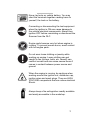
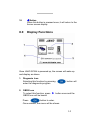
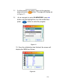
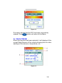
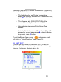
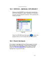
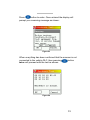
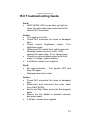
JAKO SCAN
Diagnostic Scanner
USER’S MANUAL
Version 7.2
JAKO SCAN
Contents
Page
1.0
Introduction
3
2.0
Safety Precautions
4
3.0
Diagnostic Link Connector Locations
7
4.0
Diagnostic Trouble Codes (DTC)
9
5.0
Malfunction Indicator Lamp (MIL)
11
6.0
Definition of Trip
11
7.0
Controls and Indicators
12
8.0
Display Functions
14
9.0
Getting Started
15
10.0
Operations
17
11.0
Function Descriptions
23
12.0
Toyota – AUTO SYS SEARCH
26
13.0
Toyota – MANUAL SYS SELECT
27
14.0
Check Hardware
27
15.0
Trouble Shooting Guide
29
16.0.
Disclaimer
30
17.0
Limited Warranty
31
18.0
Limitations of Warranty
32
2
JAKO SCAN
1.0
Introduction
JAKO SCAN is a diagnostic scanner which works on
Japanese (Toyota, Honda, Nissan and Mitsubishi)
and Korean (Hyundai and Kia) made vehicles.
It performs the following functions:
• Read Diagnostic Trouble Codes (DTC)
• Erase DTC
• Read Current Data stream
• Activation Test (Unit Test)
Unlike many other scanners, JAKO SCAN operates on an
embedded operating system which uses internal Flash
Memory instead of cartridges to store the car programs.
This eliminates the hassle of changing and keeping a wide
selection of program cartridges.
The unit is power up through the Diagnostic Link Connector
(DLC) most of the time but some older car models where there
was no power supplied then it needs to be powered through
the cigarette lighter adaptor which is provided.
3
JAKO SCAN
2.0 Safety Precautions:
To prevent accidents that could possibly result in
serious injury and/or damage to vehicles and/or test
equipment, carefully follow all safety rules and test
procedures when working on vehicles.
When the engine is running, it produces carbon
monoxide, a toxic and poisonous gas. Always
operate the vehicle in a well ventilated area. Do
not breathe exhaust gases – they are hazardous
that can lead to death.
To protect your eyes from propellant object as well
as caustic liquids, always wear safety eye
protection.
Fuel and battery vapors are highly flammable.
DO NOT SMOKE NEAR THE VEHICLE DURING
TESTING.
When engine is running, many parts (such as
pulleys, coolant fan, belts, etc) turn at high speed.
To avoid serious injury, always be alert and keep a
safe distance from these parts.
Before starting the engine for testing or trouble
shooting, always make sure the parking brakes
is firmly engaged. Put the transmission in Park
(automatic transmission) and Neutral (manual
transmission).
Always block the drive wheels.
Never leave vehicle unattended while testing.
4
JAKO SCAN
Never lay tools on vehicle battery. You may
short the terminals together causing harm to
yourself, the tools or the battery.
Connecting or disconnecting the test equipment
when the ignition is ON can cause damage to
the vehicle electrical components. Always turn
ignition OFF before connecting or disconnect the
Scanner from the DLC.
Engine parts become very hot when engine is
running. To prevent severe burns, avoid contact
with hot engine parts.
Do not wear loose clothing or jewelry while
working on engine. Loose clothing can get
caught in fan, pulleys, belts, etc. Jewelry can
conduct current and can cause severe burns if
comes in contact between power source and
ground.
When the engine is running, be cautious when
working around the ignition coil, distributor cap,
ignition wires and spark plugs. They are HIGH
VOLTAGE components that can cause electrical
Shock.
Always keep a fire extinguisher readily available
and easily accessible in the workshop.
5
JAKO SCAN
Important Note:
Some vehicles are equipped with SRS (Airbags).Caution
must be taken when working around the air bag components
or wiring. Always refer to the vehicle service manuals on the
CAUTION remarks. If the cautions are not followed, the air
bag may open up unexpectedly resulting in personal injury.
Note that the air bag can still open up several minutes after
the ignition key is off or even the vehicle battery is disconnected
because of a special energy reserve module.
Always follow the vehicle manufacturer’s warnings, cautions and
service procedures.
Please take note of these important points:
¾
Diagnostic Trouble Code (DTC) warns us of a
problem or symptom has occurred with a particular
engine system, not a specific part.
¾
The vehicle computer can only report Diagnostic
Trouble Code (DTC) based on what its sensors
had relayed to it.
¾
There are some instances that sensors appeared
to be bad when in actual fact, they are not.
The main causes were:
- Poor connections at the connector, broken
wire or short circuit may prevent the
sensor signal from reaching the vehicle
computer.
-
Failure of one system may affect the
sensor in another system to give false
results.
6
JAKO SCAN
¾
It is recommended that use of the vehicle service
manual to assist in the diagnosing process is
important.
The next step in diagnostic process is to test the systems
and parts that are suspected to be defective.
Once the faults had been identified and repaired, you can
use the JAKO Scan to erase the codes from the computer
memory. This will turn off the Malfunction Indicator Lamp
(MIL) or Check Engine Light.
3.0 Diagnostic Link Connector Locations:
JAKO SCAN communicates with the vehicle’s computer
modules through the Diagnostic Link Connector (DLC).
There are many types of Diagnostic Link Connectors (DLC),
as different car manufacturers use different types. The
connectors come together with JAKO Scan are equipped to
suit individual car make and also has a common OBDII
connector.
It was not until after 1996 that most of the car manufacturers
have adapted to standardize the use of OBDII - J1962
connector - Society of American Engineers (SAE)
specifications, which had standardized that all vehicles sold
in AMERICA should be OBDII compliant.
7
JAKO SCAN
The J1962 specification defines the location of the DLC in
the vehicle. See diagram below:
Figure 1
8
JAKO SCAN
4.0
Diagnostic Trouble Codes (DTC)
Diagnostic Trouble Codes are how OBDII identifies and
communicates to you with the on board computer. When the
computer recognizes and identifies a problem, a DTC for the
fault is stored in its memory. These codes are intended to
help the user to determine the root cause of the problem.
These OBDII DTC codes are made up of:
•
The 1st character in the DTC indicates a letter which
identifies the “main system” where the fault occurred
(Powertrain, Body, Chassis or Network)
•
The 2nd character is a numerical digit which identifies
“Generic or Manufacturer Specific”
•
The 3rd character is also a numerical digit which
identifies the specific systems or sub-systems where
the problem is located.
•
The 4th and 5th characters are also numerical digits
which identifies the section of the system that is
malfunctioning.
9
JAKO SCAN
OBDII DTC ANALYSIS EXAMPLE:
10
JAKO SCAN
5.0
Malfunction Indicator Lamp (MIL)
When the vehicle on board computer detects a problem in
the emission related systems or components, its diagnostic
program will assign a fault code (DTC) and safe it in its
memory and set the malfunction indicator lamp (MIL) alight.
Some faults require detection for two trips in a row before
the MIL is turned on.
Three typical examples of MIL are shown below:
Figure 2
6.0
Definition of Trip
‘A Trip’ is define as a Key-ON, Key-OFF event in which the
powertrain control module (PCM) detects the following:
• Engine coolant temperature should exceed 70oC
• Engine coolant temperature should change more
than 20oC after starting the engine.
• Engine speed should go over 400 RPM.
When the powertain control module (PCM) detects a fault
during the 1st trip, the DTC and the corresponding ‘Freeze
Frame’ data are stored in the PCM’s memory. The MIL will
not light up until the fault is again detected during the 2nd trip.
Certain DTCs are capable of turning the MIL on or blinking
during the first trip.
11
JAKO SCAN
7.0
Controls and Indicators
Figure 3
Descriptions:
1.
LCD Screen
This 160 x 160 pixels LCD screen displays all the
information relevant to the selected function during
operation.
2.
S Button
When this button is pressed once, it will scroll UP to
the previous row.
12
JAKO SCAN
3.
X Button
When this button is press once, it will turn to the next
page if there is continuation of the text.
4.
T Button
When this button is pressed once, it will scroll down
to the bottom row.
5.
This button also acts as “EXIT” button. When
pressed once, it will return to the previous screen.
6.
To increase the LCD brightness, press and hold this
button will change the screen to brighter contrast.
7.
To decrease the LCD brightness, press and hold this
button will change the screen to darker contrast.
8.
When this button is pressed once, it will turn OFF
the speaker sound totally.
9.
Pressing this button will confirm the selected
function.
13
JAKO SCAN
10.
W Button
When this button is pressed once, it will return to the
former screen display.
8.0
Display Functions
Once JAKO SCAN is powered up, the screen will wake up
and display as above.
1. Diagnosis Icon
Selecting this function by pressing
enter the diagnostic program.
button will
2. OBDII Icon
To select this function, press X button once and the
OBDII Icon will be boxed.
Press
button to enter.
Once entered, the menu will be shown.
14
JAKO SCAN
3. Self Test Icon
X button until the
Select this function by pressing
icon is boxed. This function will enter into self test
program.
4. Serial Numbers Display
The serial numbers of the scanner unit will be displayed
here.
9.0
Getting Started
JAKO SCAN aids in diagnosing and monitoring electronic and
emissions related faults in the vehicle and retrieving fault
codes related to malfunction in these systems.
Mechanical problems such as low oil level or damaged hoses,
wiring or electrical connections can cause poor engine
performance and may also cause a fault code to set.
Fix any known mechanical problems before performing any
test.
The following Areas need to be checked before starting any
test:
¾
The levels of engine oil, power steering fluid,
transmission fluid (if auto transmission), engine
coolant and other fluids must be at proper level. Top
up if necessary.
15
JAKO SCAN
¾
Check the condition of air hoses and the air filter
must be cleaned. Replace if necessary.
¾
Make sure the timing belts are in good conditions
and properly tensioned.
¾
Make sure the spark plugs are cleaned and in good
condition. Check for loose, damaged, disconnected
or missing plug cables.
¾
Make sure that all mechanical linkages to the engine
sensors (throttle, gearshift position, transmission, etc)
are secure and properly connected. Refer to Service
Manuals for locations.
¾
Check all electrical wirings and harnesses for proper
connections and condition of its insulation.
¾
Check all rubber hoses (radiator) and steel hoses
(vacuum and fuel) for leaks, cracks, blockage or
other damages.
¾
Make sure the engine is mechanically sound. Do a
compression check, engine vacuum check, timing
check, etc.
¾
Always refer to the manufacturer’s Service Manual
if you are not sure of the repair procedures.
16
JAKO SCAN
10.0 Operation
When everything had been confirmed and checked as
mentioned in 10.0 Getting Started, the testing operation can
be carried out.
1. Turn the ignition OFF.
Figure 4
2. Locate the vehicle Diagnostic Link Connector (DLC)
which is usually located under the instrument panel
(dash board), within 300 mm of the center of panel, on
the driver’s side of most cars (Refer DLC Locations on
page 8). It should be easily accessible and visible from a
kneeling position outside the vehicle with the door open.
Some European and Asian vehicles have the DLC
located on the far left corner of the dash or behind the
Ashtray (the ashtray must be removed to access it). If
the DLC cannot be located, refer to the vehicle’s service
manual.
Figure 5
17
JAKO SCAN
3. Once the DLC has been located,
connect the JAKO SCAN main
test cable with the relevant
diagnostic connector to the
vehicle’s DLC.
Figure 6
4. Turn the ignition ON and
START the engine.
Figure 7
5. When the connection has been established, JAKO
SCAN LCD screen will light up and it will display as
shown:
05044057(Licensed)
Figure 8
18
JAKO SCAN
6. Press
button will enter the diagnostic program
which shows the Menu as below:
Figure 9
7. Now you can press T or S button to select the which
country vehicle manufacturer and then confirm by
pressing
button to enter.
For Example: If JAPAN is selected and pressed OK
button to enter, the display will show the
MENU as below:
Figure 10
19
JAKO SCAN
8. Here you can select the car make by pressing T
button, the bar will straight away highlight
“MITSUBISHI” the selected manufacturer.
9. In this example, we stick to MITSUBISHI and once
confirmed with
button, the Menu will show
the car models.
Figure 11
10. To view the rest of the car models, press T
button until it reaches the end (noticed that the scroll
bar on the right also indicates).
Figure 12
20
JAKO SCAN
11.
If at this instant, you wish to return to the previous
page just press
button. The page will display as
in Figure 11.
12.
As an example to select 00 MONTERO, press S
button until the highlight bar is on this model then
press
button to enter the program.
Figure 13
13. Once the initialization has finished, the screen will
display the MENU as follows:
Figure 14
21
JAKO SCAN
14. Select the system you want to enter and press
button and the JAKO Scan will start communicating with
the engine ECU as shown below:
Figure 15
15. Once the communication has established, the screen will
display various testing functions depending on the
system that has been selected. For instance, ENG was
selected and entered; the display will show as below:
Figure 16
22
JAKO SCAN
16.
Select the function you desired and press
button and follow the instructions given on the
display.
11.0 Function descriptions:
00 READ CODES
This function when selected will retrieve the stored
Diagnostic Trouble Code (DTC) from the vehicle computer
systems memory and displayed it on the LCD screen. The
definition of the DTC is also displayed together. If there is no
fault code found it will display as follows:
Figure 17
01 CLEAR CODE (DTC)
This function is to erase or clear the Diagnostic Trouble
Code (DTC) from the vehicle computer system memory and
also the “CHECK ENGINE” light after the problem has been
rectified (Figure 18).
23
JAKO SCAN
Figure 18
The above shows that the DTC has been successfully
cleared. Press
button will return to the Menu.
02 READ STREAM
When this function has been selected, it will display all the
current Data Streams of the vehicle showing the live value
readings of the sensors, temperature, etc.
Figure 19
24
JAKO SCAN
Referring to the READ STREAM screen display (Figure 19),
it indicates the followings:
1. The highlighted bar on “Engine Temperature”
display the currently selected item. To select the rest,
press T or S button.
2. The reference data (SPECIFICATION) of the
selected item is displayed here if available.
3. Here indicates the current Data Stream Page
number.
4. Indicates the total number of Data Stream Page. To
proceed to the next page, press X button. Likewise
to go back, press W button.
To exit the Stream Page, press
button once and it
will return to “Select Function” page (Figure 16).
03 UNIT TEST
This unit test also known as activation test is to test the
functionality of the electrical components in the vehicle e.g.
injectors, fuel pumps, heaters, fans, etc.
Figure 20
25
JAKO SCAN
04
UNIT VERSION
This function is to check the vehicle computer system
version (type).
12.0 TOYOTA – AUTO SYS SEARCH
Figure 21
This function is used when either the 17pins (Circular)
or 17pins (Square) fails to detect the ECU. During the
process, the scanner will scan through its program and
once detected it will display the type: ENG & A/T-I or
ENG& A/T-II or ENG & A/T-III. With this information,
proceed to MANUAL SYS SELECT.
26
JAKO SCAN
13.0 TOYOTA – MANUAL SYS SELECT
Basing on the ENGINE type information results from
AUTO SYS SEARCH, select “MANUAL SYS SELECT”
to enter into the diagnosis program. Once entered, the
display will show:
Figure 22
Select the ENGINE type and press
button, the
program will to communicate with the vehicle ECU.
14.0 Check Hardware
The scanner is equipped with a self test program to check
the condition of the hardware. To enter into this program,
first you have to go to the Select Menu (Figure 10) and
select 03 CHECK HARDWARE by scrolling down the
highlight bar using the T button.
27
JAKO SCAN
Press
button to enter. Once entered the display will
prompt you a warning message as shown:
Figure 23
When everything has been confirmed that the scanner is not
connected to the vehicle DLC, then pressing
button
twice will proceed with the test as shown.
Figure 24
28
JAKO SCAN
15.0 Troubleshooting Guide
Fault:
• JAKO SCAN LCD screen does not light up
when the main cable was connected to the
vehicle DLC connector.
Action:
• Turn ignition key ON.
• Check DLC connector for loose or damaged
pins.
• Check screen brightness control. Turn
brightness down.
• Disconnect DLC cable from vehicle and use
alternate power source to verify. If OK,
replace the main cable. If not, replace fuse.
• Check the vehicle battery power with Multimeter. If voltage, replace battery.
• If all failed, contact your supplier.
Fault:
• No communication – Turn ignition OFF and
then ON again.
Displayed and never clear.
Action:
• Check DLC connector for loose or damaged
pins.
• Disconnect and reconnect the main cable
from JAKO SCAN.
• Exit to the Main Menu and enter the program
again.
• Ensure the Car Model is selected correctly
and enter again.
• If all fails, contact your supplier.
29
JAKO SCAN
Fault:
• Check MAC code message
Action:
• Try entering program again. If still persist
contact your supplier.
16.0 Disclaimer
All information, illustrations, and specifications
contained in this user manual are based on the latest
information available at the time of printing. The right
is reserved to make any changes at any time without
obligation to notify any person or organization of
such revisions or changes.
Furthermore, the manufacturer or its sales agents are
not liable for errors contained herein or for incidental or
consequential damages (including lost profits) in
connection with the furnishing, performance or use of
this material.
This user manual tells how to use JAKO SCAN to
perform the required procedures on vehicles. Safe and
effective use of this scanner is very much dependant on
the user following the normal practices and procedures
outline in this manual.
30
JAKO SCAN
17.0 Limited Warranty
This limited warranty cover defects in materials and
workmanship for a period of twelve (12) months which
begins from the date the product is purchased by the end
user and is subjected to the following terms and conditions:
1.
Within the warranty period, the manufacturer will
repair or replace, at their options, any defective
parts and return to the owner in good working
condition.
2.
Any repaired or replaced parts will be warranted
for the balance of the original warranty or three
months (3) months from the date of repair,
whichever is longer.
3.
This warranty only extends to the first owner and
not assignable or transferable to any subsequent
owner.
4.
Cost of delivery charges incurred for the repair
of the product to and from the manufacturer will
be borne by the owner.
5.
This limited warranty covers only those defects
that arises as a result of normal use and does
not cover those that arises as a result of:
•
•
•
Unauthorized modifications and repair.
Improper operation or misuse.
Accident or neglect such as dropping the
unit onto hard surfaces.
31
JAKO SCAN
•
•
•
•
Contact with water, rain or extreme humidity.
Contact with extreme heat.
Cables that have broken, bent contact pins
or subject to extreme stress or wear.
Physical damage to the product surface
including scratches, cracks or other damage
to the display screen or other externally
exposed parts.
18.0 Limitations of Warranty
Other than the foregoing limited warranty, the manufacturer
does not make any other warranty or condition of any kind,
whether express or implied.
Any implied warranty of merchantability, or fitness for use
shall be limited to the duration of the foregoing limited
warranty.
Otherwise, the foregoing limited warranty is the owner’s sole
and exclusive remedy and is in lieu of all other warranties
whether express or implied.
The manufacturer or any of its exclusive sales agents shall
not be liable for any consequential or incidental damages or
losses arising of the loss of uses of this product.
All warranty information, product features and specifications
are subjected to change without prior notice.
32