1
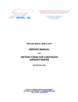
Taylorcraft Aviation, LLC
Service Bulletin No. 2007-001
2124 Central Ave
Date: October 15, 2007
Brownsville, TX 78521
Taylorcraft Considers
Phone (956) 986-0700
Compliance Mandatory
Fax (956) 986-0709
__________________________________________________________________
Revision: B (Add: X-Ray as approved Inspection, Remove Eddy Current
as Approved inspection; Extended Recurring Inspection Intervals)
SUBJECT:
Wing Lift Strut Assembly Corrosion Inspection/Replacement.
PURPOSE:
The actions specified by this Service Bulletin are intended to inspect for and detect any internal
or external corrosion of the wing lift strut tube, and thereby prevent wing strut failure and inflight separation of the wing from the airplane resulting in loss of control of the airplane. The
corrosion is most likely to occur at the lower end of the left and right wing aft and forward lift
struts (near the fuselage attachment). Since the lift struts are closed tubular structures, internal
corrosion in most cases is not readily apparent until the corrosion advances through the tube
wall. This corrosion, if allowed to progress, may lead to failure of the wing lift strut, and
probable loss of wing structure integrity. This Service Bulletin provides an inspection procedure
to detect evidence of wing lift strut tube internal and external corrosion.
FOR FURTHER INFORMATION ACCESS WWW.TAYLORCRAFT.COM OR CONTACT:
Engineering Department
956-986-0700 ext: 17
[email protected]
Parts Department
956-986-0700 ext: 14 or 15
[email protected]
EVENTS LEADING TO THE ISSUANCE OF THIS SERVICE BULLETIN:
Taylorcraft has received field reports of front and rear lift strut corrosion located within the
bottom 12 inches of the struts. The corrosion can be severe enough that in some cases in-flight
failure of the lift strut(s) may occur.
APPLICABILITY:
All Taylorcraft Aviation Airplane Models listed on Type Certificates A-696 and 1A9, to include
the following airplane models, certificated in any category:
BC, BCS, BC-65, BCS-65, BC12-65, BCS12-65, BC12-D, BCS12-D, BC12-D1, BCS12-D1,
BC12D-85, BCS12D-85, BC12D-4-85, BCS12D-4-85, 19, F19, F21, F21A, F21B, F22, F22A,
F22B, F22C.
www.taylorcraft.com
1 of 14
Taylorcraft Aviation, LLC
Service Bulletin 2007-001
NOTE:
This Service Bulletin applies to each airplane identified in the preceding applicability provision,
regardless of whether it has been modified, altered, or repaired in the area subject to the
requirements of this Service Bulletin. For airplanes that have been modified, altered, or repaired
so that the performance of the requirements of this Service Bulletin is affected, the
owner/operator must request approval for an alternative method of compliance. The request
should include an assessment of the effect of the modification, alteration, or repair on the unsafe
condition addressed by this Service Bulletin; and, if the unsafe condition has not been
eliminated, the request should include specific proposed actions to address it.
COMPLIANCE:
Perform Part 1 of the INSTRUCTIONS within the next thirty (30) calendar days. Perform Part 2
of the INSTRUCTIONS within the next three (3) calendar months; except, when corrosion is
found during Part 1 of the INSTRUCTIONS, you must perform Part 2 of the INSTRUCTIONS
prior to further flight. Re-inspect struts every forty-eight (48) months in accordance with Part 2
of the INSTRUCTIONS.
NOTE:
If the wing lift struts are new and have been installed within the last forty eight (48) months,
inspection is required no later than forty-eight (48) months after the time the new lift struts were
installed.
TERMINATING ACTION:
Installation of new replacement sealed front lift strut, (Part number MA-A815), or new
replacement sealed aft lift strut, (Part number MA-A854), is considered terminating action for
the repetitive forty-eight (48) month inspections. Note that if not all lift struts are replaced with
new sealed units, the struts that are not replaced shall be re-inspected at forty-eight (48) month
intervals.
PERSONNEL REQUIREMENTS:
The inspection procedures in Appendix A and B must be accomplished by a Level II or Level III
inspector certified in the applicable Ultrasound or Radiographic Inspection method using the
guidelines established by the American Society of Nondestructive Testing or NAS 410 (formerly
MIL-STD-410), or an Inspector certified to specific FAA, or other acceptable government or
industry standards, such as Air Transport Association (ATA) Specifications 105-Guidelines for
Training and Qualifying Personnel in Nondestructive Testing Methods, or qualified FAA Repair
Station, or a qualified Testing / Inspection Laboratory.
The person should be familiar with the test methods, know the potential types of discontinuities
peculiar to the material, and be familiar with their effect on the structural integrity of the part.
An ASNT Level III Inspector certified in radiography may adjust the procedure to fit the
equipment they are using in Appendix B.
www.taylorcraft.com
2 of 14
Taylorcraft Aviation, LLC
Service Bulletin 2007-001
INSTRUCTIONS:
Part 1
1. Clean the lower eighteen (18) inches of the right and left wing forward and aft lift struts with
a suitable cleaner to remove all dirt and grease (strut removal is not required).
2. Visually inspect the right and left wing forward and aft lift struts for corrosion or cracks
along the entire bottom twelve (12) inches of each strut. If, at any point, there is corrosion
penetrating the entire thickness of the lift strut material, the strut should be replaced before the
next flight. Clean the drain hole using safety wire or an equivalent thin gauge probe and observe
any indications of internal rust.
3. If any signs of corrosion, cracks, blistered paint, pitting, etc. of the lift strut material is
observed, or, if during the removal and installation of the lift struts for other maintenance loose
rust is heard or discovered inside the lift struts, perform Part 2 of these instructions prior to
further flight.
Part 2
1. Level the aircraft so that the lower surface of the wings is as close to level with the ground as
possible. Ideally, support the rear fuselage on a well padded sawhorse or secure stand under the
rear fuselage a foot or so forward of the tailwheel. Support and restrain the aircraft from
movement using wheel chocks, tiedowns, etc. so that the aircraft is secure in both fore-aft rolling
and tail-swing directions. Failure to properly accomplish this can lead to damage in later steps.
2. Support the weight of the outer wings so they will not drop when the strut bolts are removed.
Using a marker pen, mark the four struts with their correct position on the aircraft.
3. Carefully remove the lower strut attach nut, and remove the bolt. Put the hardware in a tray or
plastic bag for later inspection. Verify that the outer wing supports are holding the wings from
moving. The wings cannot be allowed to move in order to prevent stresses or damage to the
aileron control circuit, which is still under flight tension.
4. When the wings are verified to be secure, remove the upper strut attach bolts, and carefully
remove the struts. Be sure to remove the lower portion of the struts from the fuselage carefully,
and without any fore-aft movement so the strut mounting tabs are not bent. It is suggested to
have a helper, both for holding the weight of the strut and preventing this fore-aft movement so
you can pull the strut out in a straight movement.
5. Visually inspect the wing strut attachment fittings on each side of the fuselage for signs of
cracking or corrosion. Clean any dirt or debris from the area around the attach fittings using
suitable cleaning solution and soft bristle brush to facilitate inspection.
6. Turn each lift strut upside down and tap gently to remove any water, debris, or corrosion
particles. Clean the lower eighteen (18) inches of each lift strut with a suitable cleaner to remove
all dirt and grease.
www.taylorcraft.com
3 of 14
Taylorcraft Aviation, LLC
Service Bulletin 2007-001
7. Perform the inspection of the lower twelve (12) inches of the strut in accordance with the
inspection procedure in Appendix A (Ultrasound inspection) or Appendix B (Radiographic
inspection).
8. Verify suspected corrosion areas using a second inspection method in the appendix.
9. If no external corrosion is visible and inspection results using Appendix A or B procedure are
acceptable per ACCEPTANCE/REJECTION CRITERIA below, apply corrosion inhibitor to the
inside of each lift strut in accordance with CORROSION INHIBITOR PROCEDURE below.
10. Replace any strut having severe internal or external corrosion or that fails inspection using
the ACCEPTANCE/REJECTION CRITTERIA below. Install new sealed wing lift struts, part
numbers MA-A815 (front) and MA-A854 (rear).
11. Reinstall reusable lift struts on same side removed per LIFT STRUT WING LEVELING
PROCEDURE.
12. After inspection it may be necessary to repair/touch up external painted surfaces of the strut
surface to prevent future corrosion.
13. Acceptable struts will require a unique identifier be applied to them for future record
keeping and tracking. Rejected struts require tagging or permanent mutilation for future
inspection or scrapping.
14. Generate a report for inclusion in the aircraft history file to allow a log-book entry by the
proper authority, in compliance with applicable regulations.
SUPPLEMENTARY INFORMATION:
1. NDT inspection of the lift struts requires removing them from the airplane and testing them
on a flat, level surface. In the process of removing the lift struts, please mark each one, and upon
passing inspection reinstall it in the same position that it was removed from (i.e. the lift strut
removed from the left rear position must be reinstalled on the left rear position, and not on the
right rear position).
2. Replacement lift struts are available from the factory and terminate the recurring inspection
requirement. When ordering, please use the following part numbers:
MA-A815
MA-A854
Front Lift Strut
Rear Lift Strut
www.taylorcraft.com
4 of 14
Taylorcraft Aviation, LLC
Service Bulletin 2007-001
ACCEPTANCE/REJECTION CRITERIA:
1. The following criteria shall be used for rejection and require replacement of the strut prior to
further flight:
a. Any strut with corrosion through the thickness of the part
b. Any strut with cracks
c. Any strut exhibiting multiple pitting sites over a concentrated area
d. Any strut with corrosion that results in a remaining wall thickness of 0.020” or less over
more than one (1) square inch of the total surface area
e. Any strut with corrosion evident over 30% or more of the required inspected surface area
that results in a remaining wall thickness less than shown in the table below:
Strut
thickness (inch)
0.035 +/- 0.004
0.042 +/- 0.004
0.049 +/- 0.004
Minimum allowed
thickness (inch)
0.029
0.035
0.041
2. If at any time during testing an area is encountered where a valid thickness measurement cannot
be obtained due to a loss of signal strength or quality, the area shall be considered suspect. The
suspect area(s) shall be tested by using a second approved method in the Appendix to help determine
the extent of the corrosion. Any strut that cannot be successfully tested to determine the extent or
absence of possible corrosion, for whatever reason(s), shall be rejected and replaced prior to further
flight.
www.taylorcraft.com
5 of 14
Taylorcraft Aviation, LLC
Service Bulletin 2007-001
CORROSION INHIBITOR PROCEDURE:
Before installing reusable struts, treat each strut for internal corrosion protection per the following
procedure:
a. Inject one quart of warm raw Linseed Oil, Paralketone or CRC3 (LPS Heavy Duty Rust Inhibitor
Type 3) into the strut.
b. Plug open holes in the strut and slosh oil until interior of strut is thoroughly coated.
c. Drain oil from strut through an open hole.
d. Reinstall strut on aircraft and check rigging per LIFT STRUT WING LEVELING
PROCEDURE below.
LIFT STRUT WING LEVELING PROCEDURE:
Hold or block the wing in its approximate position while the wing struts are installed with the bolts
provided. The proper amount of incidence is built into the fuselage fittings and the dihedral is fixed by
the length of the front struts. The rear struts are adjusted at the factory and must be assemble as tagged.
After the plane is out in service, it may change balance slightly, by developing wing heaviness. To
correct this, remove the bolt at the upper end of the rear wing strut of the opposite of that which is heavy
and unscrew the plug ½ turn or more until the balance is corrected. After an airplane has received a
major overhaul, it may be advisable to check the complete rigging of the airplane. To accomplish this,
level the plane laterally by attaching a cord from wing tip to wing tip over the front spar. Place a line
level on the center of the string and level the plane by blocking up the low wheel by a jack or other
means. Level the plane longitudinally by placing a level on the stabilizer close to and parallel to the
fuselage. Use a 30” level to check the incidence at the tip of the wing, (readings to be taken on the first
full rib from the tip). By placing the edge of the level at the forward part of the rear spar along the rib
mentioned with the level in horizontal position, there will be a gap between the front edge of the level
and the wing of 1 – 5/16”. The plug at the top of the rear strut is used for adjustment.
( See Figure on Next Page (7) )
www.taylorcraft.com
6 of 14
Taylorcraft Aviation, LLC
Service Bulletin 2007-001
www.taylorcraft.com
7 of 14
Taylorcraft Aviation, LLC
Service Bulletin 2007-001
APPENDIX A
PROCEDURE AND REQUIREMENTS FOR ULTRASONIC INSPECTION OF
TAYLORCRAFT LIFT STRUTS
APPROVED PROCEDURES:
Title 14CFR part 43 requires that all maintenance be performed using methods, techniques, and
practices prescribed in the current manufacture’s maintenance manual or instructions for continued
airworthiness prepare by its manufacturer or other methods, techniques and practices acceptable to the
administrator. If the maintenance instructions include material, parts, tools, equipment, or test apparatus
necessary to comply with industry practices then those items are required to be available and used as per
part 43.
ULTRASONIC:
EQUIPMENT REQUIREMENTS:
A. A portable ultrasonic thickness gauge or flaw detector with echo-to-echo digital thickness
readout capable of reading to 0.001-inch and an A-trace waveform display will be needed to
accomplish this inspection.
B. An ultrasonic probe with the following specifications will be needed to accomplish this
inspection: 10 MHz (or higher), 0.283-inch (or smaller) diameter dual element or delay line
transducer designed for thickness gauging. The transducer and ultrasonic system shall be capable
of accurately measuring the thickness of AISI 4130 steel down to 0.020-inch. An accuracy of +/0.002-inch throughout a 0.020-inch to 0.060-inch thickness range while calibrating shall be the
criteria for acceptance.
C. Either a precision machined step wedge made of 4130 steel (or similar steel with equivalent
sound velocity) or at least three shim samples of same material will be needed to accomplish this
inspection. One thickness of the step wedge or shim shall be less than or equal to 0.020-inch, one
shall be greater than or equal to 0.060-inch, and at least one other step or shim shall be between
these two values.
D. Glycerin, light oil, or similar non-water based ultrasonic couplants are recommended in the
setup and inspection procedures. Water-based couplants, containing appropriate corrosion
inhibitors, may be utilized, provided they are removed from both the reference standards and the
test item after the inspection procedure is completed and adequate corrosion prevention steps are
then taken to protect these items.
***NOTE***
If surface roughness due to paint loss or corrosion is present, the surface should be sanded or
polished smooth before testing to assure a consistent and smooth surface for making contact with the
transducer. Care shall be taken to remove a minimal amount of structural material. Paint repairs may
be necessary after the inspection to prevent further corrosion damage from occurring. Removal of
surface irregularities will enhance the accuracy of the inspection technique.
www.taylorcraft.com
8 of 14
Taylorcraft Aviation, LLC
Service Bulletin 2007-001
INSTRUMENT SETUP:
1. Set up the ultrasonic equipment for thickness measurements as specified in the instrument's
user's manual. Because of the variety of equipment available to perform ultrasonic thickness
measurements, some modification to this general setup procedure may be necessary. However,
the tolerance requirement of step 13 and the record keeping requirement of step 14 must be
satisfied.
2. If battery power will be employed, check to see that the battery has been properly charged. The
testing will take approximately two hours. Screen brightness and contrast should be set to match
environmental conditions.
3. Verify that the instrument is set for the type of transducer being used, i.e. single or dual element,
and that the frequency setting is compatible with the transducer.
4. If a removable delay line is used, remove it and place a drop of couplant between the transducer
face and the delay line to assure good transmission of ultrasonic energy. Reassemble the delay
line transducer and continue.
5.
Program a velocity of 0.231-inch/microsecond into the ultrasonic unit unless an alternative
instrument calibration procedure is used to set the sound velocity.
6. Obtain a step wedge or steel shims per item 3 of the Equipment Requirements. Place the probe
on the thickest sample using couplant. Rotate the transducer slightly back and forth to "ring" the
transducer to the sample. Adjust the delay and range settings to arrive at an A- trace signal
display with the first back wall echo from the steel near the left side of the screen and the second
back wall echo near the right of the screen. Note that when a single element transducer is used,
the initial pulse and the delay line/steel interface will be off of the screen to the left. Adjust the
gain to place the amplitude of the first back wall signal at approximately 80% screen height on
the A-trace.
7. "Ring" the transducer on the thinnest step or shim using couplant. Select positive half-wave
rectified, negative half-wave rectified or filtered signal display to obtain the cleanest signal.
Adjust the pulse voltage, pulse width, and damping to obtain the best signal resolution. These
settings can vary from one transducer to another and are also user dependent.
8. Enable the thickness gate, and adjust the gate so that it starts at the first back wall echo and ends
at the second back wall echo. (Measuring between the first and second back wall echoes will
produce a measurement of the steel thickness that is not affected by the paint layer on the strut).
www.taylorcraft.com
9 of 14
Taylorcraft Aviation, LLC
Service Bulletin 2007-001
If instability of the gate trigger occurs, adjust the gain, gate level, and/or damping to stabilize the
thickness reading.
9.
Check the digital display reading and if it does not agree with the known thickness of the
thinnest thickness, follow your instrument's calibration recommendations to produce the correct
thickness reading. When a single element transducer is used this will usually involve adjusting
the fine delay setting.
10. Place the transducer on the thickest step of shim using couplant. Adjust the thickness gate width
so that the gate is triggered by the second back wall reflection of the thick section. If the digital
display does not agree with the thickest thickness, follow your instruments calibration
recommendations to produce the correct thickness reading. A slight adjustment in the velocity
may be necessary to get both the thinnest and the thickest reading correct. Document the changed
velocity value.
11. Place couplant on an area of the lift strut that is thought to be free of corrosion and "ring" the
transducer to surface. Minor adjustments to the signal and gate settings may be required to
account for coupling improvements resulting from the paint layer. The thickness gate level
should be set just high enough so as not to be triggered by irrelevant signal noise. An area on the
upper surface of the lift strut several inches above the inspection area would be a good location
to complete this step and should produce a thickness reading between 0.031-inch and 0.053-inch.
***NOTE***
Lift struts were manufactured from different thickness tubing, based on the availability of the
streamlined tubing at the time of manufacturing. As such, the thickness determined in this
procedure should be achieved as carefully and as precisely as possible, as it will be used as a
reference for determining the minimum acceptable thickness of the lift strut material.
12. Repeat steps 8, 9, 10, and 11 until both thick and thin shim measurements are within tolerance
and the lift strut measurement is reasonable and steady.
13. Verify that the thickness value shown in the digital display is within +/- 0.002- inch of the
correct value for each of the three or more steps of the setup wedge or shims. Make no further
adjustments to the instrument settings.
14. Record the ultrasonic versus actual thickness of all wedge steps or steel shims available as a
record of setup.
www.taylorcraft.com
10 of 14
Taylorcraft Aviation, LLC
Service Bulletin 2007-001
INSPECTION PROCEDURE:
1. Clean the lower 12 inches of the wing lift struts using a cleaner that will remove all dirt and grease.
Dirt and grease will adversely affect the accuracy of the inspection technique. Light sanding or polishing
may also be required to reduce surface roughness as noted in the Equipment Requirements section.
2. Using a flexible ruler, draw a 1/4-inch grid on the surface for a distance of 12 inches from the lower
end of the strut. This can be done using a soft felt tip pen or a silver sheet metal marking pencil, (lead
should not be used on alloy steel), depending on the color of the strut paint, and should be done on both
faces of the strut. As an alternative to drawing a complete grid, make two rows of marks spaced every
1/4- inch across the width of the strut. One row of marks should be about 10 inches from the lower end
of the strut, and the second row should be as close to the base of the lift strut as possible. Lay the flexible
ruler between respective tick marks of the two rows and use tape or a rubber band to keep the ruler in
place.
3. Apply a sufficient amount of couplant inside each of the square areas or along the edge of the ruler.
Re-application of couplant may be necessary.
4. Place the transducer inside the first square area of the drawn grid or at the first 1/4-inch mark on the
ruler and "ring" the transducer to the strut. When using a dual element transducer, be very careful to
record the thickness value with the axis of the transducer elements perpendicular to any curvature in the
strut. If this is not done, loss of signal or inaccurate readings can result.
5. Take readings inside each square on the grid or at 1/4-inch increments along the ruler and record the
results. When taking a thickness reading, rotate the transducer slightly back and forth and experiment
with the angle of contact to produce the lowest thickness reading possible. Pay close attention to the Ascan display to assure that the thickness gate is triggering off of maximized back wall echoes.
***NOTE***
A reading shall not exceed .053-inch. If a reading exceeds .053-inch, repeat steps 13 and 14 of the Instrument
Setup section before proceeding further.
6. If the A-trace is unsteady or the thickness reading is clearly wrong, adjust the signal gain and/or gate
setting to obtain reasonable and steady readings. If any instrument setting is adjusted, repeat steps 13 and
14 of the Instrument Setup section before proceeding further.
7.
In areas where obstructions are present, take a data point as close to the correct area as possible.
8. If at any time during testing an area is encountered where a valid thickness measurement cannot be
obtained due to a loss of signal strength or quality, the area shall be considered suspect. These areas may
have a remaining wall thickness of less than 0.020-inch, which is below the range of this setup, or they
may have small areas of localized corrosion or pitting present. The latter case will result in a reduction in
signal strength due to the sound being scattered from the rough surface and may result in a signal that
includes echoes from the pits as well as the back wall. The suspect area(s) shall be verified using an
alternate inspection procedure in the Appendix of this Service Bulletin.
9. Any strut that has areas of cracks or corrosion and or minimum parent metal below the thickness
limits as defined in the Service Bulletin shall be rejected.
www.taylorcraft.com
11 of 14
Taylorcraft Aviation, LLC
Service Bulletin 2007-001
APPENDIX B
PROCEDURE AND REQUIREMENTS FOR RADIOGRAPHIC INSPECTION
OF TAYLORCRAFT LIFT STRUTS
RADIOGRAPHIC TECHNIQUE: (technique reference ASTM E 94 / ASTM E 1742)
A.
B.
C.
D.
E.
F.
G.
H.
I.
J.
K.
L.
M.
N.
O.
P.
Q.
Material: Steel, (1010, 1025 or 4130).
Material Thickness: Varies from .035” to .049” dependent of type installed on aircraft.
Radiation Source: X-ray tube 150-160 kV (Lorad 160, Baltospot or similar)
Kilovoltage: 100 kv
Milliamperage: 5 M.A.
Focal Spot Size: not to exceed 1.5 mm
Source to object film distance: 24” Minimum
Film to object distance: In contact with side of lift strut
Exposure Time: 1 min 30 seconds
IQI: DIN 62 FE IQI SO 16 (steel plaque IQI may be used and shall meet the requirements of
ASTM E 1742). Plaque penetrameters shall be Group I and minimum thickness. IQI shall be
placed on the source side of the strut.
Film: Class I (Fuji 50 or equivalent)
Film Size: 14” x 17” / 7” x 17” per side
Sensitivity: 2-2T equivalent
Density Requirements: 1.5 – 4.0
Ug: not to exceed .020”
Screens: None
Cal. Std.: 0.040” to 0. 100” step wedge (steel) in 0.020” increments (or equivalent)
FILM PROCESSING: Processing may be manual or automatic; however film quality shall meet ASTM
E 94 requirements. Manual processing shall be accomplished in accordance with manufacturer’s
recommendations. The following is recommended:
A.
B.
C.
D.
E.
F.
Manual Processing
Developer: 5 min at 68F (agitate)
Stop bath: Water 1 min at 68F (agitate)
Fixer: 5 min at 68F (fix time may be adjusted to twice the clearing time)
Rinse: Water 5 min at 68F
Photo Flo: 1 min at 68F
Dry: accomplish in heated air circulating dryer
RADIOGRAPHIC EVALUATION:
Placement: the struts shall be placed on the film with the SFD as listed above. The X-ray beam shall be
oriented in the center of the film with the beam perpendicular to the area of interest. Multiple struts may
be radiographed simultaneously. Place the Calibration Standard (step wedge) adjacent to the strut on the
film.
www.taylorcraft.com
12 of 14
Taylorcraft Aviation, LLC
Service Bulletin 2007-001
RADIOGRAPHIC EVALUATION:
A. Measure the density of the film in the area next to the penetrameters and measure the density of
the film through each step thickness in Calibration Standard.
B. Plot the density measurements for each thickness in Calibration Standard (.040” to .100”). This
will result in a fairly linear curve for densities from 1.5 to 4.0 H & D.
C. Measure the density of any corroded area that appears excessive. Make a density measurement in
any area next to the corroded area. Plot the density measurement on the curve for both the area
next to the pitting and the corrosion pit itself. The difference between the two thickness
measurements is the depth of the pitting.
D. Verify undetermined thickness changes using Ultrasound method in Appendix A of this Service
Bulletin or replace strut.
Radiograph Example. Forward and aft strut of LH side. Film density 2.35 in area of interest. Film
should include applicable identification as shown above (date, airplane model and registration number)
(14” x 17”) (Calibration Standard not shown)
www.taylorcraft.com
13 of 14
Taylorcraft Aviation, LLC
Service Bulletin 2007-001
IQI placement, all wires are visible on the radiograph.
Radiographic set-up of removed struts. Struts and Cal. Std. placed on the film after removal from
aircraft. .250” lead sheet placed under film to eliminate back-scatter.
END OF DOCUMENT
www.taylorcraft.com
14 of 14