1
Floats Alaska LLC
3830 Aircraft Drive
Anchorage AK 99502
Phone: 907-248-6161
Fax: 907-245-1119
www.floatsalaska.com
Installation Instructions
for
Light Emitting Diode (LED)
Aircraft Light System
Installed in Accordance With
STC SR02394AK
For
VARIOUS MODEL ROTORCRAFT
Doc. No.:
Rev:
Dated:
LED 03-20R
A
May 15, 2012
This document and the information disclosed herein are proprietary information of Floats
Alaska, LLC. Neither this document nor the information contained herein shall be
transmitted, reproduced, copied, or disclosed in any form or by any means without the
written authorization of Floats Alaska, LLC.
The information disclosed herein includes trade secrets and confidential business and/or
financial information and falls within exemption (b) (4) of 5 USC 552 (FOIA) and the
prohibitions of 18 USC 1905.
Doc # LED 03-20R
Rev: A
1 of 11
May15, 2012
Floats Alaska LLC
3830 Aircraft Drive
Anchorage AK 99502
Phone: 907-248-6161
Fax: 907-245-1119
www.floatsalaska.com
Log of Revisions
Rev.
IR
Description
Initial release.
Pages
-
Approved
Date
10/27/2010
A
Revised STC number
1, 2
Clifford D. Belleau
5/15/2012
Doc # LED 03-20R
Rev: A
2 of 11
May15, 2012
Floats Alaska LLC
3830 Aircraft Drive
Anchorage AK 99502
Phone: 907-248-6161
Fax: 907-245-1119
www.floatsalaska.com
IMPORTANT:
PLEASE READ THROUGH ALL INSTRUCTION STEPS BEFORE
PERFORMING LIGHT SYSTEM INSTALLATION.
Table of Contents
SECTION
DESCRIPTION
PAGE
REVISION
Cover Page
1
-
Log of Revisions
2
-
Table of Contents
3
-
4-5
-
2.0
System Description and Parts
List
Component Locations
6
-
3.0
Weight and Balance
6
-
4.0
Wiring Diagram
6
-
5.0
7
-
6.0
Abbreviations, Cautions,
Warnings
Installation
7-8
-
7.0
EMI and Function Checks
9
-
8.0
Trouble-Shooting
10
-
1.0
Installation limitation:
The Whelen Parmetheus ® LED landing and taxi/hover lamps are approved
for installation only in the same location and size as replacement for
previously approved incandescent landing and taxi/hover lamps.
Doc # LED 03-20R
Rev: A
3 of 11
May15, 2012
Floats Alaska LLC
3830 Aircraft Drive
Anchorage AK 99502
1.0
Phone: 907-248-6161
Fax: 907-245-1119
www.floatsalaska.com
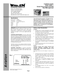
Parts List:
Item No.1
Doc # LED 03-20R
Rev: A
4 of 11
May15, 2012
Floats Alaska LLC
3830 Aircraft Drive
Anchorage AK 99502
Phone: 907-248-6161
Fax: 907-245-1119
www.floatsalaska.com
Packing List
Qty
Item
No.
1
1
PART
NUMBER
01-0771424-10
1
1
1
Title
Notes
PAR 36 LANDING
LIGHT 14V
1
01-0771424-15
PAR 36 TAXI LIGHT
14V
1
1
01-0771424-20
PAR 36 LANDING
LIGHT 28V
2
1
1
01-0771424-25
PAR 36 TAXI LIGHT
28V
2
1
1
01-0790623-10
PAR 46 LANDING
LIGHT 14V MODEL
PLED461L
1
1
1
01-0790623-20
PAR 46 LANDING
LIGHT 28V MODEL
PLED462L
2
1 – Used on 14 Volt systems only.
2 – Used on 28 Volt systems only.
Doc # LED 03-20R
Rev: A
5 of 11
May15, 2012
Floats Alaska LLC
3830 Aircraft Drive
Anchorage AK 99502
Phone: 907-248-6161
Fax: 907-245-1119
www.floatsalaska.com
2.0 Component Locations
Refer to the aircraft manufacturer’s service manual and or illustrated parts
catalog: Locate the landing and or taxi light system installed in your aircraft.
This will specify where the components are located when installed.
3.0 Weight and Balance
Component
Weight
Longitudinal Lateral
Location
Location
Whelen ® PAR36 LAMP (Rev. -) .6 LBS
Whelen ® PAR36 LAMP (Rev. A) .52 LBS
Whelen ® PAR46 LAMP (Rev. -) 1.0 LBS
Original LAMP
4.0 Wiring Diagram
Wire
Wire A
Application
Landing or Taxi Lamp
positive wire
Wire B
Landing or Taxi Lamp
ground wire
Doc # LED 03-20R
Rev: A
Manufacturers Wire Code
See airframe
manufacturers wiring
diagram
See airframe
manufacturers wiring
diagram
6 of 11
May15, 2012
Floats Alaska LLC
3830 Aircraft Drive
Anchorage AK 99502
Phone: 907-248-6161
Fax: 907-245-1119
www.floatsalaska.com
5.0 Abbreviations, Cautions, Warnings
Abbreviations:
LED
Light Emitting Diode
Cautions and Warnings:
1. Lamp contains no user repairable items.
WARNING:
If the aircraft being modified incorporates a remote sensor (flux gate)
compass: DO NOT mount the LED light within 24 inches of the remote
compass. Additionally, after installation of the LED lighting system, a
compass swing MUST be performed with the landing/taxi lights ON & OFF
and the position error card must be annotated accordingly.
WARNING:
Adequate clearance between the LED and surrounding structure must be
maintained. DO NOT mount the LED light with less than 1/8” clearance
from back of lamp to fixed structure or ¼” clearance to movable structure.
DO NOT mount the LED light with less than 4” clearance to exhaust system
components.
WARNING:
On all aircraft that are being modified it is IMPORTANT to check the size of
the power supply wire to the landing lights. Confirm that wire of sufficient
wire gauge, breaker and switch capacity is installed for the wire length.
If the aircraft power supply wire, breaker, or switch are undersize it
MUST be removed and a new wire installed in its place. Reference:
AC43.13-1B Paragraph 11-66(d) and Figure 11-2.
Doc # LED 03-20R
Rev: A
7 of 11
May15, 2012
Floats Alaska LLC
3830 Aircraft Drive
Anchorage AK 99502
6.0
Phone: 907-248-6161
Fax: 907-245-1119
www.floatsalaska.com
Removal of Original Lamps and Installation of LED Lamps
Removal:
1. Prepare the aircraft for maintenance.
(A)
Make sure all switches are in the OFF/NORMAL
position.
(B)
Disconnect the aircraft battery(s).
(C)
Disconnect external power from the aircraft.
(D)
Attach maintenance warning tags to the battery(s) and
external power receptacle that have “DO NOT CONNECT
ELECTRICAL POWER-MAINTENANCE IN
PROGRESS” written on them.
(E)
Pull landing/taxi light circuit breaker(s).
2. Reference airframe manufacturers current maintenance manual:
Remove any light cover to gain access to lamp assembly(s) and
bracket(s).
3. Disconnect connection to positive aircraft power.
4. Disconnect ground from aircraft power.
5. Remove existing lamp(s) from brackets, mark and retain hardware.
6. Record weight of removed lamp(s).
Installation:
Reference airframe manufacturer’s current maintenance manual.
1. Install LED lamp(s) in brackets using retained hardware.
2. Connect positive wire to + terminal on lamp.
3. Connect negative wire to – terminal on lamp.
4. Reinstall any light cover(s) removed to gain access to lamp
assembly(ies) and bracket(s).
5. Prepare aircraft for power up.
(A)
Make sure all switches are in the OFF/NORMAL
position.
(B)
Connect the aircraft battery(s).
(C)
Remove maintenance warning tags to the battery(s) and
external power receptacle that have “DO NOT CONNECT
ELECTRICAL POWER-MAINTENANCE IN
PROGRESS” written on them.
(D)
Engage landing light circuit breaker.
Doc # LED 03-20R
Rev: A
8 of 11
May15, 2012
Floats Alaska LLC
3830 Aircraft Drive
Anchorage AK 99502
Phone: 907-248-6161
Fax: 907-245-1119
www.floatsalaska.com
(E)
Perform an EMI and function check the system in
accordance with section 7.0.
7. Revise aircraft weight and balance and equipment list.
8. Prepare and File FAA form 337.
9. Record maintenance performed in aircraft records.
10. Perform an operational check of the landing/taxi light(s) in
accordance with 14CFR 91.407 (b) and/or (c) to determine that the
installed landing/taxi light(s) provide enough light for night
operations. If light enhancement devices are to be used, repeat the
operational check with the device(s). Record the finding(s) in the
aircraft records.
Doc # LED 03-20R
Rev: A
9 of 11
May15, 2012
Floats Alaska LLC
3830 Aircraft Drive
Anchorage AK 99502
7.0
Phone: 907-248-6161
Fax: 907-245-1119
www.floatsalaska.com
EMI and Function Check :
1. Apply power to the LED lighting system.
2. Check and record aircraft bus voltage.
3. Set the installed or handheld VHF communication radio to sweep
between 117.00 MHz and 137.00 MHz.
4. Adjust the VHF radio to the squelch activation threshold.
5. Place the antenna of the handheld VHF radio (if used) in close
proximity to the LED lamp.
6. Record radio frequencies where the VHF radio squelch activates.
7. Shut off the handheld or installed VHF radio.
8. Turn the VOR receiver(s), if so equipped, “ON.”
9. Cycle through the VOR frequencies, 108.00 – 118.00 MHz, and
record any channels with unusual background noise.
10. Turn VOR receiver(s) “OFF.”
11. Turn ADF receiver(s), if so equipped, “ON.”
12. Cycle through the ADF frequencies and record any frequencies
with unusual background noise.
13. Turn ADF receiver(s) “OFF.”
14. Operate all other aircraft systems, if installed, in all modes and
verify that there are no failures to navigational and
communications equipment during ground and flight operations.
15. Using the previously noted frequencies, determine if the newly
installed LED lighting system is the source of the EMI. This can
be accomplished by switching the LED lighting system “OFF.” If
the noise remains on the previous recorded radio frequencies, the
EMI can be attributed to some other source. Record the results of
this final procedure.
WARNING
If the aircraft to be altered has a remote mounted compass (flux gate) DO
NOT MOUNT the LED light within 24” of the remote mounted compass.
In addition to the minimum spacing it will be necessary to conduct a
compass swing of the aircraft with the LED landing light ON and OFF to
determine error in the remote compass measurements.
Doc # LED 03-20R
Rev: A
10 of 11
May15, 2012
Floats Alaska LLC
3830 Aircraft Drive
Anchorage AK 99502
Phone: 907-248-6161
Fax: 907-245-1119
www.floatsalaska.com
8.0 Trouble-Shooting Procedure:
If the system fails to illuminate when the landing light switch is activated,
you will need to trouble-shoot the system. Remember that loose connections
and corroded connections may give full voltage indications when measured
without a load.
1. In case of failure to illuminate: The input voltage to the ballast is 14 or
28 volt according to the part number (Ref: Packing List page 5).
Voltage is specified on the part label at the + terminal. Troubleshoot
as follows:
a. Check for bus voltage at power input wire to the lamp.
Reestablish power if inadequate power is found.
b. Check for proper lamp part number per the aircraft
manufacturer’s system voltage.
c. Check for excessive resistance at lamp ground and repair if
necessary.
d. Disconnect lamp, bench check lamp using verified power
source of proper output. If lamp does not function, replace
lamp.
************************* E N D ****************************
Doc # LED 03-20R
Rev: A
11 of 11
May15, 2012