1
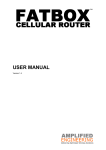
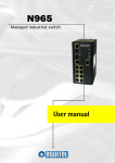
AMPLIFIED
ENGINEERING
FATBOX B.A.S.E MANUAL
VERSION 1.2
THE FATBOX B.A.S.E
CONTENTS
Our motto . . . . . . . . . . . . . . . . . . . . . . . . . . . . . . . . . . . . . . . .
4
7. Working the Web Console
What’s in the Box? . . . . . . . . . . . . . . . . . . . . . . . . . . . . . . . . . 5
Important Safety Notice . . . . . . . . . . . . . . . . . . . . . . . . . . . . . 6
7.1.1
Application Configure . . . . . . . . . . . . . . .
1. Product Specifications . . . . . . . . . . . . . . . . . . . . . . . . . . . .
7
7.1.2
Services Configuration . . . . . . . . . . . . . . 19
7.1.3
Ethernet Configure . . . . . . . . . . . . . . . . . 20
2. System Requirements
7.1 System Parameters
17
2.1 Power Supply Details . . . . . . . . . . . . . . . . . . . . . . 8
7.1.4
Serial Configure . . . . . . . . . . . . . . . . . . . 22
2.2 Cellular Data Network Provider . . . . . . . . . . . . . . .
8
7.1.5
Timer Configure . . . . . . . . . . . . . . . . . . . 23
2.3 Ethernet Devices . . . . . . . . . . . . . . . . . . . . . . . . . .
9
7.1.6
Timer Up Down . . . . . . . . . . . . . . . . . . . 23
2.4 Serial Devices . . . . . . . . . . . . . . . . . . . . . . . . . . . .
9
7.1.7
Reboot Redial Conditions . . . . . . . . . . . 24
3. FATBOX Hardware . . . . . . . . . . . . . . . . . . . . . . . . . . . . . . .
10
7.1.8
Advanced Parameters . . . . . . . . . . . . . . 24
4. FATBOX Dimensions and Installation . . . . . . . . . . . . . . . . .
13
7.1.9
AT over Ethernet . . . . . . . . . . . . . . . . . . 25
5. Hooking Up the FATBOX to Devices
7.1.10 Backup Routing . . . . . . . . . . . . . . . . . . . 26
5.1 Ethernet Devices Settings
7.2 Network Configuration
5.1.1 Using the DHCP . . . . . . . . . . . . . . . . . . . 14
7.2.1
NAT . . . . . . . . . . . . . . . . . . . . . . . . . . . . 5.1.2 Setting Hosts manually . . . . . . . . . . . . . .
14
7.2.2
Ifconfig . . . . . . . . . . . . . . . . . . . . . . . . . . 28
5.2 Serial Device Settings . . . . . . . . . . . . . . . . . . . . . .
15
7.2.3
Static Route . . . . . . . . . . . . . . . . . . . . . . 29
7.2.4
AutoPing . . . . . . . . . . . . . . . . . . . . . . . .
29
6. Logging in & Saving Changes (via the Web Console)
27
6.1 Logging In to the FATBOX . . . . . . . . . . . . . . . . . . . 16
7.2.5
DHCP . . . . . . . . . . . . . . . . . . . . . . . . . .
29
6.2 Saving Changes Made . . . . . . . . . . . . . . . . . . . . . .
16
7.2.6
DDNS . . . . . . . . . . . . . . . . . . . . . . . . . .
30
7.2.7
NTP . . . . . . . . . . . . . . . . . . . . . . . . . . . .
30
COLOR LEGEND
7.2.8
PPTP . . . . . . . . . . . . . . . . . . . . . . . . . .
31
7.2.9
L2TP . . . . . . . . . . . . . . . . . . . . . . . . . . 32
7.2.10 IPSEC . . . . . . . . . . . . . . . . . . . . . . . . .
33
7.2.11 VRRP . . . . . . . . . . . . . . . . . . . . . . . . . .
33
7.2.12 VLAN . . . . . . . . . . . . . . . . . . . . . . . . . .
34
7.3 Security Configure . . . . . . . . . . . . . . . . . . . . . . . . . 7.4 System Manage
35
7.4.1
System Tools . . . . . . . . . . . . . . . . . . . .
37
7.4.2
User Manage . . . . . . . . . . . . . . . . . . . .
38
7.4.3
Device Status . . . . . . . . . . . . . . . . . . . .
38
8. Connecting via TELNET - Settings & Configurations
8.1
Logging In . . . . . . . . . . . . . . . . . . . . . . . . . . . . . . 39
8.2
Cellular Operator Settings . . . . . . . . . . . . . . . . . . 39
This manual is color-coded for your ease of reference.
normal text
actions
product specs
windows commands
web console headers
9. Configurations via the Serial Port
9.1
Logging in via the Serial Port . . . . . . . . . . . . . . . .
40
9.2
Serial Console Commands . . . . . . . . . . . . . . . . . .
40
9.3
Reverting to Factory Default
9.3.1
The RESET Button . . . . . . . . . . . . . . . .
41
9.3.2
Via Web Browser . . . . . . . . . . . . . . . . . 41
9.3.3
Via the Serial Port . . . . . . . . . . . . . . . . .
41
10. Contacting Us at Amplified Engineering . . . . . . . . . . . . . . .
42
table info
critical!
AMPLIFIED
ENGINEERING
Delivering Optimized Wireless Solutions is
our motto.
If you have any help requirements, please
do not hesitate to contact our Solution
Partners or the FATBOX
Head Office ;)
CONTACT DETAILS ON PAGE 42.
Please download latest user manuals at www.amplified.com.au
pg.4
Thank you for purchasing the FATBOX B.A.S.E. HSUPA broadband cellular router. Inside your FATBOX packaging, you will find:
·
1 X FATBOXTM B.A.S.E. HSUPA Router
·
1 X Tuned GSM antenna
(with 2M wire)
·
1 X Yellow CAT5 LAN cable
·
1 X Serial diagnostics cable
·
1 X Appropriate power supply unit
IN THE BOX
(12VDC output)
pg.5
w IMPORTANT SAFETY NOTICE
All specialist electronic devices must be operated with due
care to avoid damage or injuries and should be installed and
operated by a trained personnel.
DO NOT OPERATE THIS EQUIPMENT IN ENVIRONMENTS
CONTAINING POTENTIALLY EXPLOSIVE GASES OR LIQUIDS,
EXAMPLE, GAS STATIONS AND CHEMICAL PLANTS AND
EXPLOSIVE STORES.
pg.6
1. PRODUCT SPECIFICATIONS
The FATBOX B.A.S.E integrates an M2M-rated HSUPA (+GSM) module with an efficient ARM7 processor and runs a multi-function firmware in Linux OS.
Its rugged industrial design is fit for demanding remote and mobile data connectivity applications.
Wireless Cellular Interface
Operating System
·
·
·
·
·
·
HSUPA for 7.2Mbps download and 3.6Mbps upload over
850/900/1900/2100MHz bands
GSM 850/900/1800/1900 for GPRS/EDGE
SMS and CSD 14.4kbps supported
RX Diversity antenna support for mobile applications
LAN Interface
·
·
·
2 x 10/100BaseT Ethernet ports
DHCP as default
VLAN supported
Serial Interface
·
·
·
To operate as serial modem
(e.g. for SMS, CSD)
For TCP/UDP transparent transport mode
As a back-up route
(e.g. to serial SAT modem)
LINUX OS on ARM microprocessor
Kernel and Firmware update over TCP or Serial
Other Features
·
·
·
·
·
·
·
·
·
·
·
·
·
Automatic WAN/ADSL backup to HSUPA
Wake on LAN/Serial data
Wake on LAN/Serial call
SMS to reboot FATBOX B.A.S.E remotely
AT over Ethernet for sending SMS or to manage device
locally
SNMPv1 for Network Management Systems
Supports VPN [IPSEC (PSK), PPTP and L2TP]
DDNS
DMZ & NAT
IP Firewall
VRRP (Virtual Router Redundancy Protocol)
Configurable PPP keep alive function
Backup route using serial to external modem
Power and Operating Conditions
In the Box
·
·
·
·
·
·
·
·
·
Power: 5 – 30VDC (200mA~150mA 12VDC)
Operating Temperature: -20°C to +65°C
Physical dimensions: 130mm x 92mm x 25mm
Weight: 400gm
FATBOX B.A.S.E HSUPA Router
GSM antenna (with 2 meter wire)
CAT5 LAN cable
Serial cable
Power supply unit (12VDC)
pg.7
2. SYSTEM REQUIREMENTS
B.A.S.E manual 1.2
2.1 Power Supply Details
The power requirements for the B.A.S.E are as following:
Supply
5 – 30VDC regulated power supply recommended (e.g. 12VDC @ 1A)
Consumption
100 ~ 150mA @ 12 VDC (Cellular network not connected)
200 ~ 250mA @ 12VDC (Cellular network connected and transmitting)
w
w
Inadequate current or dips in voltage may cause the device to fail to connect to data services even if the LEDs are lighted up.
Supply over 30 VDC will damage the device.
2.2 Cellular Data Network Provider
The FATBOX B.A.S.E is designed to be a reliable broadband cellular device that is able to operate in the following frequencies:
pg.8
Frequency
Bands
UMTS: Quad Band 850/900/1900/2100MHz
HSUPA/HSDPA: 850/900/1900/2100MHz
GSM/GPRS/EDGE: Quad Band 850/900/1800/1900MHz
Output
Power
Class 4 (+33dBm ± 2dB) for EGSM/GPRS 850
Class 4 (+33dBm ± 2dB) for EGSM/GPRS 900
Class 1 (+30dBm ± 2dB) for GSM/GPRS 1800
Class 1 (+30dBm ± 2dB) for GSM/GPRS 1900
Class 3 (+24dBm +1/-3dB) for UMTS 2100, WCDMA FDD Bdl
Class 3 (+24dBm +1/-3dB) for UMTS 1900, WCDMA FDD Bdll
Class 3 (+24dBm +1/-3dB) for UMTS 900, WCDMA FDD BdVIII
Class 3 (+24dBm +1/-3dB) for UMTS 850, WCDMA FDD BdV
w
Please ensure that the SIM card to be used has PIN disable and HSUPA, EGPRS or GPRS data plans enabled. You will need to
check with your Network Operator for configuration information like APN, dial-number, username and password.
2. SYSTEM REQUIREMENTS
B.A.S.E manual 1.2
2.3 Ethernet Devices
In the factory default, the B.A.S.E has two IP addresses. The respective IP address for the Ethernet ports are as follows:
PORT
IP ADDRESS
SUBNET MASK
LAN
192.168.1.1
255.255.255.0
ETH2
138.0.19.1
255.255.255.0
You can either let the inbuilt DHCP server assign IP addresses to connected devices automatically (by default) or configure the
attached hosts with fixed IP addresses. See Section 5.1.2 on page 14 for more information on how to do this.
2.4 Serial Devices
In the factory default, the B.A.S.E’s serial port is designated as a serial terminal console that continuously sends a debug log.
This helps to ease device troubleshooting.
But the serial port can also be configured to function as a serial modem, back up route or a TCP/UDP transparent transport
channel. See section 7.1.4 on page 22 for information on how to do this.
pg.9
3. FATBOX HARDWARE
(I) Hardware RESET
Press 1 – 9 Seconds
Press >10 Seconds
B.A.S.E manual 1.2
(II) LED Indicators
Soft Reset
Revert configuration to Factory Settings
The FATBOX B.A.S.E LEDs are useful indicators of the unit’s current operating status and should be
used for initial setup and troubleshooting of the router.
LED
Indication of
LED Status
PWR
Power Supply
LED ON
RUN
Startup Stage
Flash Once every 3 Seconds
Flash Twice every 3 Seconds
Network Connection
Flash Once every 1 Second
LED ON
LED OFF
NET
Network Type
GREEN
RED
Signal Strength
ON
Flash Once every 3 Seconds
Flash Twice every 3 Seconds
pg.10
Router Status
Power is supplied
to router
Router Initializing
Router failing Initialization
PPP dialing
PPP online
PPP offline
2G (GPRS/EDGE) network
3G/HSDPA network
Signal is strong
Signal is normal
Signal is weak
3. FATBOX HARDWARE
(III) SIM Card (or USIM)
(IV) Antenna (ANT1 & ANT2)
The SIM card to be used is the ‘mini’ USIM type of ISO/IEC 7810:2003,
ID-000 standard, i.e. 25 X 15mm. Push gently the yellow button to eject
SIM carrier. SIM card should be inserted into the carrier as indicated.
w
NEVER remove or insert SIM card when device has PWR switched in “ON” position. Damage caused to device or SIM in such case will not
be warranted.
B.A.S.E manual 1.2
The supported antenna is a 50W SMA Male. This antenna must be designed for the network
frequency that the device is operating in. For normal uses set up the antenna on the ANT1 slot.
ANT2 is a RX Diversity antenna connection, adding it will give the router better HSUPA downlink
data performance in mobile applications.
Please contact [email protected] or a reseller partner if you need to utilize the RX diversity antenna or purchase a specialized antenna such as a high gain or outdoor antenna.
Note: The performances of the device, especially for HSUPA operations, are very much affected by
the signal strength of the network operator.
pg.11
3. FATBOX HARDWARE
(V) Power Source (DC)
pg.12
If you are providing your own power source, please ensure it adheres to the following specifications:
Power Connector:
Female 5.5mm X 2.1mm plug is required
(+VE TIP)
A 12VDC with 1A rated regulated power supply is recommended for maximum power efficiency.
(VI) Serial Ports (SERIAL)
The serial port is useful for the
manipulations of B.A.S.E units
remotely. The port may also be used
as a serial modem, the configuration
to set the B.A.S.E as a serial modem is
on page 22, section 7.1.4.
B.A.S.E manual 1.2
(VII)Ethernet Ports
The B.A.S.E has two 10/100BaseT Auto-Negotiation Ethernet ports.
(i) For normal applications with only a single host,
LAN should be used.
(ii) In “WAN to HSUPA backup” applications, ETH2 is
connected to the network’s WAN modem (e.g. a
DSL/ADSL modem)
Note: The maximum Ethernet cable length is 100 meters.
4. FATBOX DIMENSIONS AND INSTALLATIONS
B.A.S.E manual 1.2
The case of the B.A.S.E is made with sheet steel that provides sturdy protection for the electronics and serves as an EMR Shield at the
same time. The removable “L” mounting plates should be used to mount the router to a secure structure or a mounting plate within
an electronic enclosure.
\
Installation Orientation: For most efficient cooling, the router should be mounted vertically with the antenna-side facing up to
allow for natural convection.
\
Antennas must be mounted external of any shielded metal enclosure and secured to a large metal plane for best
performance. A good example is the middle of a vehicle’s metal roof.
\
Vibration – in conditions where strong vibrations are expected (for example in locomotives) the FATBOX should be mounted
with a vibration dampening material in between the box and the mounting surface. This isolation helps to dampen the
transmission of shocks that may otherwise damage the device over time.
pg.13
5. HOOKING UP THE FATBOX TO DEVICES
B.A.S.E manual 1.2
5.1 Ethernet Device Settings
5.1.1
5.1.2
Using the DHCP to deploy addresses automatically
The FATBOX’s DHCP server is enabled
by default and its IP addresses
are 192.168.1.1 (port ‘LAN’)
and 138.0.19.1 (port ‘ETH2’).
For your initial setup, we suggest
setting your computer’s LAN Internet
Protocol (TCP/IP) to automatic. Do
this by going to: Control Panel>
Network and Sharing Center>
LAN Configure> TCP/IP (IPv4) u
Properties v> Obtain IP address
automatically w.
Setting host addresses manually
Alternatively, you may choose to manually
configure your device so it has a fixed local
IP address. Input the IP address following this
format.
w
u
v
IP address
·
·
Subnet Mask
Usually automatically set to 255.255.255.0
Default
Gateway
·
·
Preferred and
Alternate DNS
Server
pg.14
1. The host ID XXX should be a number between 2 to 254 and should not be duplicated within the same local network.
192.168.1.XXX1 if you have connected it to port ‘LAN’ or
138.0.19.XXX if your connection is to port ‘ETH2’
192.168.1.1 if you have connected to port ‘LAN’ or
138.0.19.1 if you have connected to port ‘ETH2’
Obtain DNS server addresses automatically or Choose your
own DNS Servers
5. HOOKING UP THE FATBOX TO DEVICES
B.A.S.E manual 1.2
5.2 Serial Device Settings
If you are connecting a serial device to the FATBOX for Serial Log Monitoring, Serial DTU (Transparent Transport) or Serial Modem, you will need
to set the device’s serial port to the following setting to initiate a connection.
Baud Rate
115200 bps
Data Bits
8 Data Bits
Stop Bits
1 Stop Bit
Parity Check
No Parity Bit (None)
Flow Control
No Flow Control (None)
If you want to configure the serial ports to your own settings you may do so via the serial configure menu in the web console. Refer to section
7.1.4 on page 22 to read about configuring the serial port.
pg.15
6. LOGGING IN AND SAVING CHANGES IN THE WEB-CONSOLE
B.A.S.E.manual 1.2
6.1 Logging in to the B.A.S.E
Connect your computer to port LAN on the B.A.S.E with the Ethernet CAT5 cable provided. Wait a few moments for your computer to register the device then open your web browser and type in “192.168.1.1” into the URL tab (We advise users to turn off their laptop’s wireless connection to avoid the chance of any clashes in IP addressing during the log in process).
Enter as following in the LOGIN page:
USERNAME: admin
PASSWORD: 12345
You may change the username and password from within the console.
The DHCP server is activated by default. It will assign a local IP address of 192.168.1.2 to the first Ethernet device attached to port ‘LAN’. The first Ethernet device attached to port ‘ETH2’ will be given an address of 138.0.19.2.
6.2 Saving Parameter Changes
After the making changes to your FATBOX’s configuration, you have to go to System Manage > System Tools and Save the parameter changes to Flash and RESET as following.
j
Choose “Save Parameters to Flash” j and click on SET k.
l
k
pg.16
Then you may reset the system by choosing “Reset System” l and then click “SET” k. Alternatively you may choose to reset by unplugging the power cord for a few seconds. The new settings will be in place when the B.A.S.E reboots.
w IMPORTANT: Please wait till the message “Parameters Save Success” is displayed before resetting the FATBOX. A premature reset may corrupt the unit’s configuration. If this happens you will need to use the serial console to load the default settings to the box. (See section 9.3.3 on page 41 to do this.)
7. WORKING WITH THE WEB CONSOLE
B.A.S.E manual 1.2
Welcome to the FATBOX Web-Console menu. If you are already logged in, the following segment will run you through the various settings and
configurations you can make through your web browser. Please ensure that you have covered segment 6.2 on saving parameter changes before you
continue. The web console is recommended for users who prefer having an intuitive interface to manage their routers.
7.1 System Parameters
The FATBOX B.A.SE is smartly designed so that a single product may be deployed in a variety of ways around your network in a cost effective
manner. Section 7.1 covers how to set up the B.A.S.E to the way that you’ll like to use it.
7.1.1
Application Configure – the B.A.S.E may be applied as a Router, an M2M (Client or Server) or as a Modem.
W Router Mode
The Router mode is
set by default.
W Serial Transmit Mode
The most common applications of the Serial Transmit Mode are:
-
A ‘point-to-point’ topology where a FATBOX connects directly to another FATBOX. This networks the communication
between the two serial ports. The initiating router’s Application Rule is ‘Client’ and the other is ‘Server’.
-
To connect the FATBOX directly to a server via TCP/IP (e.g. for metering)
pg.17
7. WORKING WITH THE WEB CONSOLE
B.A.S.E manual 1.2
User can select to use TCP or UDP to transmit
the serial data
Sets router as the ‘Client’ or as the ‘Server’
For applications like metering, set to ‘Client’
Rule.
Local port selected for the transmission.
Other router’s IP address
Other router’s port selected
W MODEM MODE
pg.18
Select Modem mode
To configure the FATBOX to work as a serial modem please proceed to “Serial Configure” (Section 7.1.4) to set up
the serial port configuration to work with your local device.
7. WORKING WITH THE WEB CONSOLE
7.1.2
B.A.S.E manual 1.2
Services Configuration
To begin connecting to a cellular data network you will need to set up the Services Configuration menu found in System Parameters.
Note that much of the information required here would have to come from your cellular operator.
Set to ‘Auto’ unless you want to limit
connection to a particular network.
Choose specific bands if you want to limit your
connection to particular networks
For some networks, router can get settings
automatically. Set to ‘Appointed’ and manually
enter settings if unsure.
Ask service provider. It’s something like
“telstra.internet” or “tmobile”.
Ask service provider. Usually it is “*99#” or
“*99***1#”.
Ask service provider. Not always necessary.
Check the “Username and Password Blank”
box if service provider requires the two fields
to be left blank.
If you want the B.A.S.E to be always on operation click the “SET” button to confirm the settings now. Otherwise continue to
configure the following section.
pg.19
7. WORKING WITH THE WEB CONSOLE
B.A.S.E manual 1.2
Check Data Trigger if you want the B.A.S.E to
only go online when there is incoming serial
data or if it receives a Wake Up call.
Check “RING” to allow incoming call to Wake
Up unit for PPP reconnection.
Check “CALLER ID WHEN WAKE ” if you want
authentication against the caller’s number (Set
in Section 7.3.8 - Advanced Parameters)
Check to disconnect PPP and Sleep when the
Ethernet port is idle longer than the “Wait
Time” set. This saves costs for users with
infrequent data transmissions on metered
data plans.
7.1.3 Ethernet Configure
You can configure the B.A.S.E’s Ethernet ports to function in the 4 different modes described below.
W Normal Mode
pg.20
In this mode, the BA.S.E functions as a
gateway where the two Ethernet ports
work as separate subnets to connect to
the Internet or VPN via the cellular
network.
7. WORKING WITH THE WEB CONSOLE
B.A.S.E manual 1.2
W PPPoE Mode
The PPPoE mode enables the B.A.S.E to
dial-up via a separate modem. The WAN
(e.g. ADSL) modem should be set up in
the ‘Bridge’/‘PPPoE Relay’ Mode and
connected to the B.A.S.E’s ETH2 port. It
is important to prevent the WAN modem
from connecting automatically in this set
up so that the B.A.S.E will be assigned
with the network’s IP address.
W EWAN Mode
In this mode, all the LAN traffic is
uplinked via ETH2. In the example given,
the FATBOX is connected to the ADSL
modem with IP address 10.1.1.1.
W Bridged Mode
In this mode, both the LAN and ETH2
ports are bridged and will have the same
Ethernet IP address and subnet.
pg.21
7. WORKING WITH THE WEB CONSOLE
7.1.4
B.A.S.E manual 1.2
Serial Configure
The serial port may be used for one of three operations
·
·
·
By default, as a “COM” port for making configurations, event logging or flash uploading
As a Transparent TCP or UDP port (e.g. a DTU) in “COM” mode - See
also Section 7.1.8, Output Debug Info on Serial Port.
As a “MODEM” Serial Port (e.g. for Dial Up networking or for Sending/Receiving SMS)
The factory default settings.
This is the max serial data that the router can send
during the “Max Data Send Interval”.
This configuration decides how often the serial port
data will be sent when you are using the TCP or UDP
Serial Transmit mode.
pg.22
This configuration decides how often the TCP or UDP Transparent Transport port transforms serial data
7. WORKING WITH THE WEB CONSOLE
7.1.5
B.A.S.E manual 1.2
Timer Configure
Here you can set the router to automatically reconnect PPP sessions or reboot.
Configures the dwell time between ‘Retry-to-Connect’
PPP sessions with Data Service Provider. Configure
between 10 to 15 seconds.
Configures the number of times the FATBOX tries to
connect PPP sessions with the Data Service Provider
before it reboots. Set between “1~60” times or “0” for
infinite retries without rebooting (default).
The other settings in this segment are for specific network operations and we do not advise the normal user to make any
modifications there.
7.1.6
Timer Up-Down
If the GPRS or NTP time sync2 is reliable upon power up, the FATBOX can be programmed to have specific PPP connection and
disconnection times each day.
2. See Section 7.2.7 for NTP
Check to Enable,
Enter [Hour : Minute : Second] to set PPP
reconnection time for each day.
Enter [Hour : Minute : Second] to set PPP disconnection time for each day.
pg.23
7. WORKING WITH THE WEB CONSOLE
7.1.7
7.1.8
B.A.S.E manual 1.2
Reboot Redial Conditions
This is a custom application specific function. Please contact [email protected] for advanced user application support.
Advanced Parameters
You can use this menu to configure some of the specific parameters outlined below.
Web Manage System Port: By default it is set to 80. You may change
it to improve security if the router is on a public IP network.
PPP authentication mode: Please ask Network Service Provider or
else leave as it is. It can be configured to “PAP Only”, “CHAP Only” or
“CHAP first and then PAP” (default).
Control Host IP address: Registers the IP address of the host that
controls the PPP connection.
Wake Up Phone Number: Configures the Caller ID to authenticate
incoming calls for the “Remote Wake Up Manner: RING” (See
Services Configuration, Section 7.1.2).
Enable PPP Parameter Configure: If checked it will allow for the
advanced configuration of PPP negotiation.
Output Debug Info on Serial Port: The default Serial Setting
[115200/8/1/NoneParity/NoneFlowControl] is configured to “0”
(i.e. Serial Port Debug Mode). If the router’s serial port is used for
data transmission (e.g. TCP Serial Mode), this box must be checked.
SMS to Reboot: The FATBOX can be rebooted remotely via SMS from
a specific cell phone.
Enter the phone number sending the SMS to the FATBOX
Enter the SMS ‘string’ to reboot the FATBOX
pg.24
7. WORKING WITH THE WEB CONSOLE
7.1.9
B.A.S.E manual 1.2
AT over Ethernet
This is useful to allow local host devices that are connected by Ethernet to send an SMS or check the module’s status by using
AT commands.
Note that a “?” will be returned if the HSUPA Module is not ready (e.g. still negotiating a PPP session) instead of a typical “OK”.
Enables AT over Ethernet function
Choose TCP or UDP Protocol
Select the port number of the FATBOX to connect to its HC25 Module
(by default the port used is 2008)
Example Application: A PLC sends an SMS alert to the B.A.S.E while it is still connected to the Internet as a router. Assuming the
default settings (shown above) is used, the following TCP messages will be sent to 192.168.1.2:2008.
Commands Issued
Description
AT+CMGF=1
To engage TEXT mode (instead of PDU mode)
AT+CSCA=”+61418706700”
Sets the SMS Center number of the cellular data provider (e.g. for Telstra Australia)
AT+CMGC+”+61XXXXXXXX”
Sets the mobile number that will receive the SMS (+61XXXXXXXXX)
ALARM!
The message to be sent is “ALARM!”
<CTRL-Z>
Sends the message
pg.25
7. WORKING WITH THE WEB CONSOLE
B.A.S.E manual 1.2
7.1.10 Backup Routing
Type 1: Back up a Primary WAN connection (e.g. an ADSL modem) using Wireless (HSUPA)
The B.A.S.E can automatically back up failed WAN connections to HSUPA.
If the B.A.S.E is not able to get a PING response from a target server after certain number of tries, it will switch the data
route to the HSUPA link. The route will be switched back if PING response (via the WAN port) has recovered.
pg.26
Check to enable back up function
Choose either EWAN or PPPoE depending on WAN operator/ modem
Choose HSUPA connection as “Always On” or “On Demand”
Configure to match LAN connection of WAN modem
Sets timing and external targets to ‘test’ PING response
Configure to local LAN requirements, e.g. a remote office net
7. WORKING WITH THE WEB CONSOLE
B.A.S.E manual 1.2
Type 2: Back up a Primary Wireless connection (HSUPA) using a WAN connection (e.g. an ADSL modem)
Check to enable back up function
Select “Via Wireless” (WAN backs up over
ETH2)
Choose either EWAN or PPPoE depending on
WAN operator/ modem
Applicable for PPPoE dial-up for WAN mode
Configure to match LAN connection of WAN
modem
Configure to local LAN requirements, e.g. a
remote office net
7.2 Network Configuration
7.2.1
NAT
For flexible LAN setups, FATBOX supports both DMZ and NAT (Network Address Translation) configurations.
Check to enable DMZ to a specific host
Enter DMZ host address
\ DMZ must be DISABLED in order to allow Port Forwarding (NAT)
pg.27
7. WORKING WITH THE WEB CONSOLE
B.A.S.E manual 1.2
Choose an appropriate protocol (TCP or UDP).
Enter in the Source port as well as the
destination address and port.
Adds a new port forwarding function
Deletes a selected port forwarding function
In the cited example, if a public IP (whether static or resolved by DDNS) of 222.222.222.222 is assigned by the network service
provider, then pointing a remote application to 222.222.222.222:88 will connect it to local device 192.168.1.2’s port number 80
(web server).
7.2.2
IfConfig
The router can be accessed through an additional IP address via its LAN/ETH2 port if IfConfig is set up.
pg.28
Check to enable Ifconfig
Adds a an additional alias and IP address
Deletes a selected alias and IP address
In the example given, Ethernet Alias is formatted
as “eth0:xxx” to give an additional interface to access the router.
7. WORKING WITH THE WEB CONSOLE
7.2.3
7.2.4
B.A.S.E manual 1.2
Static Route
If you are set up for PPTP or IPSEC VPN,
it is a typical requirement to configure
your Static Route table to route VPN
address packets via the VPN gateway
and interface instead of an unsecured
cellular gateway.
Auto PING
The Auto PING function reboots the B.A.S.E after the maximum number of PING failure from the target server IP. This is useful
as in many cases the reboot frees a ‘locked’ PPP session.
7.2.5
Enables Auto PING function
Target server’s external IP address
FATBOX reboots after this number of PING response failures from the target server
DHCP
The FATBOX router has two Ethernet ports
(LAN and ETH2) with independent configurable
modes and interfaces.
In the Ethernet Bridged Mode (Section 7.1.3 on page 21) the eth0 settings will be used for the bridged subnet.
In the factory default, the DNS addresses are configured to point to OpenDNS server addresses.
pg.29
7. WORKING WITH THE WEB CONSOLE
7.2.6
B.A.S.E manual 1.2
DDNS (Dynamic DNS)
In many cellular data networks, the provisioning of static and public IP is a difficult and often expensive exercise. If public IP is
available, FATBOX can be configure to register its assigned remote public IP address to a DDNS service provider (e.g dyndns.org) so
that its session’s temporary IP can be resolved by a unique domain name.
\
Troubleshooting: Serial connection is required to access
the serial console (See section 9). Enter “set advanced”
and configure the DDNS debug information setting.
When DDNS (and PPTP) serial debug mode is ON, the
serial terminal must be connected to enable sessions to
be completed.
7.2.7
NTP
NTP (Network Time Protocol) is
a protocol to synchronize the
clocks of computers over a network.
The FATBOX router can update its
internal clock upon power up and
connection to the Internet. This clock
can be used to control the router’s PPP
connection and disconnection and is also
used for some VPN protocols.
pg.30
After troubleshooting is completed, please disable the debug to allow the FATBOX to operate without a serial device attached.
7. WORKING WITH THE WEB CONSOLE
7.2.8
B.A.S.E manual 1.2
PPTP
Please configure PPTP settings to match your PPTP VPN server settings. In some cases you will also need to configure the
router’s Static Route (see section 7.2.3) to enable proper routing of VPN traffic via the PPTP tunnel.
Check to enable PPTP tunneling
Enter the PPTP server that the router will connect to
Enter the Username and Password for the PPTP authentication
Enable MPPE encryption (Check with PPTP VPN server)
Enter the IP Address of the subnet on the server side
Enter the Subnet Mask on the server side
Check to assign VPN IP address to both client and server sides of the PPTP. The PPTP server should also be configured with this option also.
Enter the Client side IP address of the PPTP
Enter the Server side IP address of the PPTP
pg.31
7. WORKING WITH THE WEB CONSOLE
7.2.9
B.A.S.E manual 1.2
L2TP
FATBOX can support L2TP tunneling either as a Client or a Server (Supporting up to a maximum of 16 Clients).
Check to enable L2TP tunneling
Select FATBOX as a L2TP Client or Server
Enter the IP Address of the L2TP Server (FATBOX as a
L2TP Client)
Enter the IP addresses that the FATBOX will assign to
L2TP Clients (FATBOX as L2TP Server)
Enter the Username for L2TP tunnel authentication
Enter the Password for L2TP tunnel authentication
Enter the L2TP server side subnet IP Address L2TP tunnel
Enter the L2TP server side subnet mask
pg.32
7. WORKING WITH THE WEB CONSOLE
B.A.S.E manual 1.2
7.2.10 IPSEC Tunnel
FATBOX supports IPSEC (PSK) tunnels to an
IPSEC VPN Server configured to the following
settings.
Using IKE
Exchange Mode: Main Mode
Remote Identity Type: IP Address
Using Pre-Shared Keys (PSK)
Encryption Algorithm: MD5
Configurable MTU, SA and IKE Lifetime
Enable/Disable PFS
The configuration and deployment of IPSEC is exact and expected to be configured by expert networking engineers with working knowledge of their IPSEC VPN servers at their back-office. Please contact [email protected] for further information.
7.2.11 VRRP
Virtual Router Redundancy
Protocol (VRRP) enables two
or more configure routers to
‘switch’ between themselves,
electing a primary router based
on their VRRP priority assigned.
pg.33
7. WORKING WITH THE WEB CONSOLE
B.A.S.E manual 1.2
Connect the FATBOX via the ETH2 port to the network of other routers and network devices.
Priority assigned to each router. Choose from 1 to 254, the larger
number has higher priority.
Enter the Virtual Router’s IP Address. Assign the same IP address
on each VRRP router.
Elapsed time for VRRP Master to send multicast packets to all
registered routers, failure to do so will cause the next ranked
VRRP router to take over.
All VRRP routers in the network must have the same broadcast IP.
It is by default 224.0.0.18 but is modifiable.
7.2.12 VLAN
pg.34
Enabling VLAN allows the FATBOX to work with VLAN-aware switches by assigning one of its Ethernet interface a suitable VLAN ID
and IP address.
7. WORKING WITH THE WEB CONSOLE
7.3
B.A.S.E manual 1.2
Security Configure
FATBOX supports Iptable input and
output table configuration. Iptable
scripting is also supported.
pg.35
7. WORKING WITH THE WEB CONSOLE
pg.36
Basic Iptables (v1.2.7a) scripting commands are listed below for guidance.
B.A.S.E manual 1.2
7. WORKING WITH THE WEB CONSOLE
7.4
B.A.S.E manual 1.2
System Manage
7.4.1
Systems Tools
In this section are the system management tools for flash, kernel, parameters management and also the configuration of
username and password to access the router. You can also find useful information about the cellular signal strength and basic
connection of the device under the Device Status tag.
Check and Click “SET” to write the
changes to the FATBOX’s flash.
w
Do not reboot/power-down
the device until the writing process
is acknowledged as completed.
(In order to run in an ETH-attached
computer you will require a TFTP
program such as tftpd32.) Check
“Download Parameter” to save
FATBOX Configuration parameters
to a text file (e.g. parafile). You
can then modify the file with a
text editor and upload back to
the FATBOX using the “Upload
Parameter” feature. You will be
required to indicate the computer’s
IP address and the parameter file
name. When you are done, save
the parameter to flash and reset
the router.
Allows uploading of the FATBOX
parameters to Factory Default.
Note that if the flash is corrupted,
access to the Web Console may
not be possible and the Factory
Default will have to be load via the
Serial Console. (See section 9.3.3)
w
DO NOT EXECUTE unless
under guidance of an Amplified
Engineering technical support
staff as the device’s flash kernel or
firmware could be corrupted if not
done correctly.
pg.37
7. WORKING WITH THE WEB CONSOLE
7.4.2
B.A.S.E manual 1.2
User Manage
You may change the FATBOX’s log in page’s
Username and Password settings for better
security. To revert back to factory default
see section 9.3 on page 41.
7.4.3
Device Status
This page provides real time update of the router’s operation and network status, e.g. network signal strength and status,
assigned IP addresses and VPN status.
The table below will be able to give you some helpful tips regarding the level of Signal Strength
Quality of Signal
Levels
Description
Marginal -95dBm or lower. At these sort of levels, it is very likely that you may suffer low throughput and disconnects due to cell loading/breathing
even with an outdoor antenna.
Workable under
-85dBm to -95dBm. most conditions
Probably worth considering an outdoor gain type antenna. Could
suffer poor throughput and disconnects due to cell loading/breathing.
Good -75dBm to -85dBm Normally no problem holding a connection with this sort of level (even with cell breathing) without the use of an external antenna.
Excellent Above -75dBm Should not be affected by cell breathing/loading and should not require an external antenna.
pg.38
8. CONFIGURATIONS VIA TELNET
In the case that your browser is unable to connect to the FATBOX, you can still configure the device via TELNET.
\ You must be able to ‘ping’ the device in order to TELNET.
8.1
8.2
B.A.S.E manual 1.2
Logging In
Open a new command prompt session (Windows START>Run> Type “cmd” <Enter>).
Enter “telnet 192.168.1.1” and the screen on the left will be shown.
Enter “cfg” and complete the log in within 10 seconds (The default Username is “admin” and password is “12345”).
Enter “set msc” at the “DTU>” prompt.
Enter the parameters provided by your cellular operator.
Enter “sa” to save changes to the router’s Flash memory.
You can now reboot the box by entering “reset” or by switching off its power for a few seconds.
for saved changes is displayed before resetting the FATBOX.
A premature reset may corrupt the unit’s configuration. If this happens you will need to use the serial console to load the default settings to the box. (See section 9.3.3 to do this.)
Configuring Cellular Operator Settings
w IMPORTANT: Please wait till the acknowledgement message pg.39
9. CONFIGURATIONS VIA THE SERIAL PORT (ADVANCED USERS ONLY)
9.1
B.A.S.E manual 1.2
Logging in via the Serial Port
If the FATBOX’s firmware or parameters are corrupted, there is the possibility that the FATBOX may not respond to ‘ping’, TELNET or the web
browser. You will need to access the box via its serial port to return the parameters in flash to the factory default.
Set the computer’s serial port to the following configuration via a
HyperTerminal program.
Once you are connected, keep the ‘SPACE’ key pressed while
switching ON the FATBOX.
When prompted, please enter the username and password. If
you have not changed the Log in settings the default username
and password are as following.
USERNAME:
PASSWORD: 9.2
Serial Console Commands
All configuration commands are available via the Serial Console.
As this mode is to be used by network professionals, this manual
will not cover the usages of other commands.
To see a list of available commands type “?”.
To display all settings and useful information
for troubleshooting type “show all”.
The Serial console configuration is for advanced users.
Please email [email protected] for technical assistance.
pg.40
admin
12345
9. CONFIGURATIONS VIA THE SERIAL PORT (ADVANCED USERS ONLY)
9.3
B.A.S.E manual 1.2
Revert to Factory Default
9.3.1
The RESET Button
The easiest method to revert the router’s configuration to factory default is to depress the RESET switch on the top of the router
for 10 seconds.
9.3.2
Via Web Browser
If your are able to access the FATBOX’s web configuration pages, please got to section 7.4.1 to “Load Default Parameter” via the
System Tools menu.
9.3.3
Via the Serial port
The FATBOX’s Flash memory may have been corrupted if the box was powered down before it had completed saving changes.
As the result the DHCP function may not work and the user would not be able to access the router via the web browser or by
TELNET.
To revert the B.A.S.E to factory default, complete the log
in process described in section 9.1
After you are logged in enter the following commands
1. Enter “load def” to load default
2. Enter “sa” to save the changes to Flash
3. Wait for the acknowledgement to complete before
rebooting the FATBOX B.A.S.E
pg.41
10.CONTACTING US AT AMPLIFIED ENGINEERING
B.A.S.E manual 1.2
Your first call for support should be your local FATBOX solutions partner. If that fails to solve your problems or answer your queries,
please contact us via [email protected] and we will get back to you latest the next business day.
Amplified Engineering Pty Ltd
Level 29 Perth Forrest Centre
221 St. Georges Terrace
Perth Western Australia 6000
AUSTRALIA
pg.42
B.A.S.E
amplified.com.au
amplified.com.au