
1
MY-ZB010C-S/P Module User Manual MY-ZB010C-S/P User Manual V1.3 MY-ZB010C-S/P Module User Manual Version History Version V1.0 Description Initial Version Time 2014.3 Add network scanning function Acquisition network address and MAC address of source node from reply on remote command Optimizing entry and exit of TP module Optimizing IO acquisition and AD acquisition V1.1 Save configuration parameters to FLASH by “AT+W” 2014.6 command Add join network control and lock on to the network function Add single data packet sending function by AT command Update the AT command parameters string to 128 bytes Pass-through optimization: support 400 bytes emergency transfer, support smaller packages transferring at greater V1.2 frequency 2014.7 Increase neighbor table size and routing table size Add routing table validity checking mechanism Optimize network scanning command execution, realize network time difference response Add automatically reporting about network access Add network nodes start-up with time difference to support V1.3 2014.8 large-scale network power-on at the same time Support optional AT command response, which enables frequently quick access control from RSSI to LQI Support single channel, not channels set MY-ZB010C-S/P Module User Manual Directory Directory ............................................................................................................................... 1 Chapter 1 Introduction ......................................................................................................... 4 1.1 Overview ................................................................................................................. 4 1.2 Product Overview ................................................................................................... 4 1.3 Feature ................................................................................................................... 4 1.4 Specifications.......................................................................................................... 5 Chapter 2 Module Interface ................................................................................................. 8 2.1 Pin Definitions......................................................................................................... 8 Chapter 3 Function Introduction ........................................................................................ 11 3.1 ZigBee .................................................................................................................. 11 3.1.1 ZigBee Device Types ................................................................................. 12 3.1.2 ZigBee Network .......................................................................................... 13 3.2 Working Mode ...................................................................................................... 16 3.3 AT Command Mode .............................................................................................. 16 3.3.1 Introduction................................................................................................. 16 3.3.2 Local and Remote AT Commands............................................................. 17 3.4 TP Data Pass-through Mode ................................................................................ 18 3.4.1 Introduction................................................................................................. 18 3.4.2 TP Mode Setting and Entry/Exit ................................................................. 19 3.4.3 Switch to the AT Mode Actively .................................................................. 22 3.4.4 Two Application Forms ............................................................................... 22 3.4.5 Flow Control ............................................................................................... 23 3.5 Send/Receive Single Packet Data via AT Commands ......................................... 24 3.6 The Default Working Mode and Starting Process ................................................ 24 3.7 Join to Network, Lock Network and Off-grid Control of Equipment ..................... 25 3.7.1 Applications requirement............................................................................ 25 1 MY-ZB010C-S/P Module User Manual 3.7.2 Solutions..................................................................................................... 26 3.8 IO Pass-through ................................................................................................... 30 3.9 Control of IOs ....................................................................................................... 31 3.10 IO Sampling ........................................................................................................ 31 3.11 AD Sampling ....................................................................................................... 32 3.12 PWM Output ....................................................................................................... 32 3.13 Node Descriptor.................................................................................................. 33 3.14 Report information automatically........................................................................ 33 Chapter 4 AT Command .................................................................................................... 35 4.1 Command Format................................................................................................. 36 4.2 Command Summary Table ................................................................................... 37 4.3 Command detail ................................................................................................... 39 4.3.1 Set and Query UART ................................................................................. 39 4.3.2 Basic Network Settings .............................................................................. 47 4.3.3 Superior Network Setting ........................................................................... 56 4.3.4 TP Data Pass-through ................................................................................ 66 4.3.5 System-related ........................................................................................... 69 4.3.6 IO Control Pass-through ............................................................................ 72 4.3.7 AD Acquisition ............................................................................................ 78 4.3.8 PWM Output ............................................................................................... 81 4.3.9 Other .......................................................................................................... 83 4.4 Error Codes .......................................................................................................... 85 Chapter 5 Application Examples........................................................................................ 88 5.1 UART Parameter Configuration ........................................................................... 88 5.1.1 UART Hardware Connection ..................................................................... 88 5.1.2 Configuration Steps .................................................................................... 89 5.1.3 Attention ..................................................................................................... 89 5.2 Network Parameter Configuration ........................................................................ 90 5.2.1 Configuration Steps .................................................................................... 90 5.2.2 Attention ..................................................................................................... 91 2 MY-ZB010C-S/P Module User Manual 5.3 TP Pass-through Configuration ............................................................................ 92 5.3.1 Configuration Steps .................................................................................... 92 5.3.2 Attention ..................................................................................................... 94 5.4 IO Pass-through Configuration............................................................................. 95 5.4.1 Configuration Steps .................................................................................... 95 5.4.2 Attention ..................................................................................................... 96 5.5 Control/Read the IO of a Remote Node ............................................................... 96 5.5.1 Configuration Steps .................................................................................... 97 5.5.2 Attention ..................................................................................................... 98 5.6 IO Timed Acquisition configuration ....................................................................... 98 5.6.1 Configuration Steps .................................................................................... 98 5.6.2 Attention ..................................................................................................... 99 5.7 AD Timed Acquisition Configurations ................................................................... 99 5.7.1 Configuration Steps .................................................................................... 99 5.7.2 Attention ................................................................................................... 100 5.8 PWM Output Configuration ................................................................................ 100 Chapter 6 Package Dimensions ...................................................................................... 101 3 MY-ZB010C-S/P Module User Manual Chapter 1 Introduction 1.1 Overview MY-ZB010C is an industrial-grade ZigBee transmission control module launched by MYIR. It supports AT command/remote AT command and provides point-to-point, one-to-many data pass-through function. It also provides periodical AD acquisition, periodical IO acquisition, IO level pass-through control, and PWM output functions. The AT command/ remote AT command can directly control all modules’ IO, AD, and PWM within network, which can better support acquisition control of the cloud platform. The versatility makes MY-ZB010C an ideal communication control module for smart home, intelligent energy control, remote monitoring, medical monitoring, warehouse environment monitoring, building automation, etc. 1.2 Product Overview Figure 1-1 1.3 Feature Industrial Grade Design: High-performance industrial-grade ZigBee chip; Operating temperature:-40~+85Celsius; 4 MY-ZB010C-S/P Module User Manual Operating voltage: DC2.0~3.6V. Reliability: The WDT ensures system’s long-term stability; The design of hardware flow control and end-to-end flow control ensure the integrity of data communication. Easy to Use Minimum running requirement: VCC, GND, TXD, and RXD; The AT command configuration supports remote AT commands, which enables remote acquisition or control of any module online; Enter data pass-through mode when power up. Powerful functions: 2.4Ghz working frequency; ZigBee Pro protocol, mesh network, support up to 65535 nodes theoretically; Stable long-distance communication: line-of-sight communication distance is up to 2.2 km for the high-power module and up to 200 m for the standard power module; Support point-to-point data pass-through and one-to-many data pass-through; Support IO level pass-through and point-to-point IO control; Peripherals:4 ADC channels, 3 PWM outputs, 5 IO 1.4 Specifications Model Specifications: Models Explanations MY-ZB010C-S Standard Power Module, Antenna Onboard, Stamps Hole Package MY-ZB010C-P High Power Module, UFL Antenna Interface, Stamps Hole Package Table 1-1 Network Specifications: Parameters Network Protocol Explanations IEEE 802.15.4 ZigBee Pro (ZigBee 2007) 5 MY-ZB010C-S/P Module User Manual Frequency Channel ISM 2.4G, 11-26 Channel Network Topology Point to Point, Star Network, Mesh Network Theory Bandwidth 250 Kbps Measured Bandwidth of 29.6 Kbps Application Layer MY-ZB010C-S: 2.5dBm Transmit Power MY-ZB010C-P: 22dBm MY-ZB010C-S: -95dBm Receiver Sensitivity MY-ZB010C-P: -100dBm Line-of-sight MY-ZB010C-P: 2.2km Communication Distance MY-ZB010C-S: 200 m Table 1-2 Interface Specifications: Interfaces Explanations Baud Rate: 4800、9600、19200、38400、76800、115200 Data bits: 5、6、7、8 Parity: None, odd parity, even parity UART Stop bits: 1, 2 Flow Control: None, hard flow control Level: 3.3V, TTL level High Power Module: UFL Connector Antenna Interface Standard Power Module: Antenna Onboard, Package Interface Stamps Hole Package Table 1-3 Power Specifications: Parameters Explanations Recommended Voltage DC 3.3V Operating Voltage 2.0-3.6V Electric Current High Power Module 6 Send Current 175mA Receive Current 22mA MY-ZB010C-S/P Module User Manual Parameters Explanations Low Power Module Idle Current 10mA Send Current 15.3mA Receive Current 17mA Idle Current 8mA Table 1-4 AD Specifications: Parameters Explanations Precision 10 bit Reference voltage DC 2.47V Maximum input voltage for AD channels 0V~2.47V Table 1-5 PWM Output Specifications: Parameters Explanations Max Working Frequency 10 KHZ Min Working Frequency 20 HZ Table 1-6 Working Temperature: Parameters Explanations Working Temperature -40~+85 Celsius Storage Temperature -40~+125 Celsius Welding Temperature 280~320 Celsius Table 1-7 Overall Dimensions: Parameters Explanations Dimensions 30mmX16mmX3mm(Length * width * thickness) Weight 3g Table 1-8 7 MY-ZB010C-S/P Module User Manual Chapter 2 Module Interface 2.1 Pin Definitions Pin configuration is shown in Figure 2-1: ADC1 ADC2 DIO17 NFRST NC NC NC SIF_D/DIO15 SIF_CLK/DIO14 NC VDD GND NSIG PWM1 DIO9 DIO10 PWM2 NC TXD NC RXD RESET PWM3 CTS RTS ADC3 ADC4 Figure 2-1 Pin configuration is as shown in Table 2-1. A: Analog; D: Digital; I: Input; O: Output; PWR: Power NC: Not Used. NO Name I/O Description 1 ADC1 AI ADC Input Channel 1 2 NC - NC 3 NC - Download mode pin must be pulled 4 NC - NC 5 NC - NC 6 ADC3 AI ADC Input Channel 3 8 Note [1] [1] MY-ZB010C-S/P Module User Manual NO Name I/O 7 ADC4 AI 8 NC - Description ADC Input Channel 4 Note [1] High-power module pin must be left unconnected High-power module pin must be left 9 NC unconnected 10 CTS DI CTS [2] 11 RTS DO RTS [2] 12 TXD DO UART Output 13 RXD DI UART Input 14 NSIG DO Network status signal output 15 DIO9 DIO GPIO 16 DIO10 DIO GPIO 17 VCC PWR VDD 18 GND PER GND 19 PWM1 DO PWM Output Channel 1 20 PWM2 DO PWM Output Channel 2 21 PWM2 DO PWM Output Channel 3 22 RESET DI Module Reset Signal , Active Low DIO I2C clock signal , GPIO SIF_CLK/DIO 23 [3] default 14 DIO14 default 24 SIF_D/DIO15 DIO I2C data signals ,GPIO DIO14 Keep low-level for 3s to restore factory 25 DIO16 DIO settings 26 DIO17 DIO GPIO 27 ADC2 AI ADC Input Channel 2 [1] Table 2-1 [1] Analog input cannot exceed the maximum input voltage of 2.7V, and should be 9 MY-ZB010C-S/P Module User Manual isolated from digital circuits. [2] When hardware flow control is enabled, low-level is active; when hardware flow control is disabled, it is recommended to drop it down. [3] When network module is running normally, the output signal cycle is: 1760ms low, 80ms high low. The graphic is shown as follows: Figure 2-2 When the module is disconnected, the output signal cycle is: 1000ms low, 1000ms high. The graphic is shown as follows: Figure 2-3 10 MY-ZB010C-S/P Module User Manual Chapter 3 Function Introduction 3.1 ZigBee ZigBee is a low-speed, short-range wireless network transmission protocol which is based on the IEEE 802.15.4 standard specification media access layer and physical layer. The main features include low-speed, low power, low cost, low complexity, deployment fast, secure, reliable and supporting massive network nodes and a variety of network topologies. ZigBee network applications in smart home, warehouse monitoring, control/acquisition, etc, has the following advantages: 1) Self-organized network The self-organized characteristics of ZigBee network makes it easier to form a wireless network. As long as the network devices (nodes) are within each other's communication range, ZigBee network can automatically connect all the devices (nodes) to form a mesh network. 2) Network coverage ZigBee network belongs to the multi-hop network: long distance communication between two devices (nodes) can be accomplished via data forwarding function of other devices (nodes) online. Therefore, network communication coverage for ZigBee network can be extended under both indoors and outdoors circumstances. 3) Easy to extend and network topology modifiable Add a device to a ZigBee network (node) is very convenient: within the communication range of the ZigBee network, new equipment can automatically join the network, which in return expands the original ZigBee network coverage. On removing a router in the network devices (nodes), the ZigBee network will automatically adjust the network topology to adapt to the change of network physical location, keeping the whole network’s connectivity. 11 MY-ZB010C-S/P Module User Manual 4) High security The ZigBee network joining control can be set to: verify access, or open access at certain time slice; data transmission via ZigBee network is encrypted by the AES 128 - bit encryption standard to ensure data security. 3.1.1 ZigBee Device Types There are three kinds of ZigBee devices, namely, the coordinator, router node and end device. ZigBee sets up an initial network firstly by the coordinator nodes, and then the other router nodes and end devices join the initial network to form a whole network. Coordinator: A ZigBee network must have, and only one coordinator. The coordinator, which is responsible for the formation of networks, selects the basic network parameters as network communication channel, network ID, EPID etc, and then accepts the other nodes (routers and end devices) to join the network to form an autonomous LAN. The coordinator can also send and receive data, forward data and participate in routing. Router: Router is a kind of nodes with routing function which can rout not only for data forwarding and data relaying, but also for receiving and sending data. Router can be the parent of other nodes. A ZigBee network can have multiple routers, which connect each other to form a mesh network and implement the functions of data forwarding, relaying, and routing scanning. End device: End device is a kind of nodes without routing function. The end device node cannot be a parent node but can only receive and transmit data through its parent node. ZigBee network topology is shown in Figure 3-1: 12 MY-ZB010C-S/P Module User Manual Figure 3-1 3.1.2 ZigBee Network ZigBee networking process can be divided into two steps. Firstly, coordinator set up the basic network, and then other nodes join the network. In order to better illustrate the networking and communication process. Firstly, let’s interpret some basic network parameters and its main role. Physical channel (Wireless frequency): The MAC layer and the physical layer of ZigBee protocol are defined by IEEE 802.15.4 standard. IEEE 802.15.4 standard defines three working frequency bands: 2.4GHz (Global), 868MHz (Europe) and 915 MHz (USA), which can reaches the highest 250kbit/s, 20kbit/s and 40kbit/s respectively. Due to packet overhead and processing delay, the actual data throughput will be less than a predetermined bit rate. These three bands have 27 selectable operating channels: 868MHz (one channel, NO: 0), 915MHz (10 channels, NO: 1-10), 2.4GHz (16 channels, NO: 11-26). MY-ZB010C module uses 2.4GHz, channel number 11-26. A network can only communicate on one channel. In the initial stages of building network, the coordinator is responsible for selecting a network channel. 13 MY-ZB010C-S/P Module User Manual Network ID: Namely PID, a 16bit integer stands for a network ID. All nodes within one network have the same PID. Different networks have different PIDs. PIDs distinguish two different ZigBee networks running the same channel in adjacent area. Coordinator scans the surrounding network environment to select a none-conflicting network PID in the initial stages of building network. PID is selected automatically according to ZigBee protocol and cannot be pre-set by users. Extended network ID: Namely EPID, a 64 - bit integer value, used to distinguish between different network applications. Network node can only join a network with the same EPID, EPID value of all within the same network ZigBee nodes must be the same. EPID complete set by the user, they can set a private EPID to deploy all ZigBee devices form a network of self-government. EPID can also be set to 0. In this case, the coordinator will use its own MAC address as the network EPID on building a network; while other nodes will no longer search for a specified EPID to join a network, but select a network to join according to certain selection standard. Any node can join a ZigBee network when EPID for 0. Address: Network address (NID) and MAC address (MID). The network address is a 16bit integer, and the MAC Address is a 64bit integer. Therefore, network address is also known as short address and MAC address is called as long address. Network address is a dynamically allocated value when a node joining the network. Network address cannot be set by the user, but can be inquired. The network address of coordinator is fixed at 0x0, network addresses of other nodes are allocated, when node joining the network, by their parent node based on certain allocation algorithm. MAC address is a fixed globally unique address. Generally speaking, MAC address is cured inside the module and cannot be changed. Therefore, MAC address identifies a node uniquely. After joining the network, MAC address can be inquired based on the network address, network address can also be inquired based on MAC addresses. Network addresses are dynamically allocated and cannot be fixed. Therefore, it is proposed to use the MAC address for communication. However, in some network applications when data needs to be sent to coordinator node, users can use network address for communication, 14 MY-ZB010C-S/P Module User Manual as network address of coordinator is fixed to 0x0. You can use the network address or the MAC address for communication. Network address 0xFFFF and MAC address 0xFFFFFFFFFFFFFFFF is broadcast address. 1 Set up network by coordinator: The coordinator is responsible for network formation, which is the first startup network node. If the other nodes start first, they will, according to a presetting, scan the target network nodes to join. But the other nodes cannot join the network successfully until the coordinator has successfully formed a network. The formation of a network is as follows: 1) Set EPID: When EPID set to 0, the coordinator uses its own MAC address as the network EPID; otherwise, the coordinator uses the setting EPID as network EPID. 2) Select the physical channel: Scan network environment in the user-defined channels. 3) Select the network PID: In the selected channel, detect the existing networks and their PIDs by listening, and then select a no conflict PID in the same channel for establishing network. 4) Wait for other nodes to join: After the above 3 steps, coordinator completes the establishment of network, then can accept the other nodes (router or end device) to join network. 2 Router or end device join the network: Routing or end device node can join the ZigBee network pre-established by the coordinator through choosing a coordinator or router as its parent node. The specific steps are as follows: 1) Search Network: when a node scans running networks in a pre-set physical channel, the node may find multiple running ZigBee networks and joins the network with EPID the same as the user-defined one. If the default EPID is 0, the node will join a network by certain priority; otherwise it will join the specified network. If no network is detected or the specified EPID cannot be detected, then node fails to join the network, but the module will repeatedly try this process until success or users interrupt. 2) Select the parent node: After searching for the appropriate network, there may 15 MY-ZB010C-S/P Module User Manual be one or more nodes can accept the current node. The node can select a parent node to join the network based on the combination of network depth, signal quality, etc. 3) Send a request to join: After selecting parent node, the current node sends request to candidate parent node, and then waits for the response. 4) Join the network and get a network address: The candidate parent nodes response a network join request, and distribute a network address to the requestor. The requestor can send and receive data after they successfully get join to the network. 3.2 Working Mode The module has two kinds of working mode: the AT command mode and TP data pass-through mode. 1 AT command mode: This working mode is mainly used to configure, exquisite, and control the module itself and other modules in the network. When the module is working under the AT command mode, all data received from the UART are parsed as an AT command. 2 TP data pass-through mode: This working mode is used to transmit data. When the module is working under the TP data pass-through mode, all data received from the UART are treated as pure data, which will be send to the specified device. Module can be switched freely between the AT command mode and TP data pass-through mode. In the AT command mode, send "AT+TPMOD\r\n" instruction to get into to the TP data pass-through mode; On the other hand, send "+++"(Attention: there is no carriage return or newline following the string "+++") can switch back to the AT command mode. 3.3 AT Command Mode 3.3.1 Introduction An AT command refers to a command string that starts with AT, appends command string and parameters, and terminates with the string "\r\n" (ASCII code 0x0D, 0x0A). For 16 MY-ZB010C-S/P Module User Manual example, "AT+CH=26\r\n". AT command mode is mainly used to configure module parameters and to execute specific commands. In AT command mode, host (PC or MCU) sends AT commands through the UART to module for setting and querying specific parameters, such as EPID, physical channel and so on. Users can also send executable command by AT commands, such as starting the network, set the IO output equality, PWM output, AD value, send a single packet data, receiving a single package, etc. In AT command mode, all characters sent to the module by UART will be parsed as AT command. If the format and parameters of AT command is correct, the module executes AT commands and returns the results. In AT command mode, users can set various parameters by AT commands one by one for application purpose. 3.3.2 Local and Remote AT Commands The so-called local AT commands is that AT commands are executed by the local nodes and connected with the host by UART. While remote AT commands refers to sending AT commands by ZigBee network to remote node for execution. As shown in Figure 3-2: CMD Local AT command Host MY-ZB010C RSP ZigBee network CMD Remote AT command Host MY-ZB010C MY-ZB010C RSP Module A Module B Figure 3-2 Host sends AT commands directly to module A, who is the command executor. This kind of AT commands is called as local AT command. If the host sends a remote AT commands to module A, but the AT command is executed on module B rather than module A. Module B can receive AT commands through the network interface for remote configuration. Enable remote configuration, control and sample. We can deploy and control a ZigBee network merely by remote AT commands. We can get access to and control all the resources in network from the UART of the center 17 MY-ZB010C-S/P Module User Manual device (node). The resources include IO controlling and acquisition, AD acquisition, PWM output, query configuration, lock/unlock on to the network, etc. The format of local AT command and remote AT commands are almost same. Their difference is that remote AT commands append destination node type and address directly to corresponding local AT commands. AT command does not support remote broadcast destination address. 1. Remote node may be in off-network state after the execution of certain remote AT command, the remote node at this state can't receive remote the AT command through the ZigBee network until the node joining the network again; 2. It is not recommended to switch a remote node into TP mode via the remote AT command; 3. It is not recommended to force a remote node to perform network scanning via the remote AT command; 4. To sum up, on using the remote AT command, please note: "Whether or not a node is in a connected state after it has performed the remote AT command ". For detailed AT command format and functional descriptions, please refer to the following chapters. For detailed description about the remote AT command, please refer to Chapter 4. 3.4 TP Data Pass-through Mode 3.4.1 Introduction In the TP data pass-through mode, the module receives data from a UART and sends to the specified destination node. Destination node (module) receives data from the ZigBee network, and sends data to the host (PC/MCU) by UART as shown in Figure 3-3: 18 MY-ZB010C-S/P Module User Manual Receive data ‘ABCD’ HostA Send data ‘ABCD’ Wireless pass through UART UART Device A HostB Device B Zigbee Receive data ‘4321’ Send data ‘4321’ Figure 3-3 3.4.2 TP Mode Setting and Entry/Exit 1 Pass-through address settings You must have set the TP model parameters for a device before it switch into TP pass-through mode. The TP model parameters are mainly pass-through address settings. Pass-through address is the address of the destination node when a module in pass-through mode. Use <address mode, address> to describe a destination node. Here, “address mode” can be set to network address or MAC address. Network address is a 16 bit integer, the MAC address is a 64 - bit integer. You can use the “AT+TID” instruction to set the pass-through module address, such as “AT+TID=NID,0x1234” represents that the pass-through destination is the node with network address 0x1234,and “AT+TID=MID,0x1234567887654321” represents that the pass-through destination is the node MAC address 0x1234567887654321 The network address 0xFFFF and MAC address 0xFFFFFFFFFFFFFFFF are broadcast address. When the broadcast addresses are used as pass-through address, the module will broadcast the data to the entire network. Please refer to Chapter 4 for detailed descriptions. 2 Enter the TP mode After configure the pass-through address, send "AT+TPMOD\r\n" command to request the module to enter the TP pass-through mode. The process of entering TP pass-through is as follows: ① First start the current network; ② If the TID is a broadcast address, the node switches into the TP pass-through mode 19 MY-ZB010C-S/P Module User Manual directly and outputs "+TP_MODE:\r\n" from the UART, tipping the host: "The module has entered the TP data pass-through mode". ③ If TID is not a broadcast address, the requesting node begins to connect to a remote destination node by sending a TP request packet to the remote destination node. The TP request packet includes the network address and MAC address of the destination node. When the remote destination node receives this TP request packet, it replies an ACK packet denoting that it is ready for data pass-through from the requesting node if the pass-through address of the remote destination node is the requesting node or the broadcast address. At the same time, the remote node will automatically enter into TP data pass-through mode (On the remote node entering into the TP pass-through mode, the message "+TP_MOD:\r\n" will output from the UART). If the pass-through address of the remote destination node is not the requesting node, nor the broadcast address, the remote node replies a NOACK package denoting refusal of data pass-through. ④ If the requesting node receives an ACK packet, the nodes successfully connects with the TP mode, and the message "+TP_MODE:\r\n" will output from the UART denoting: "the module has entered the TP data pass-through mode"; If the requesting node receives NOACK package or receives nothing within 5s(overtime), the message "ERR=<Error code>" will output from the UART informing the host "An error has occurred on entering the TP data pass-through mode". More detailed explanation above process: 1) The module will automatically start network when it enters into TP mode. For the coordinator, starting network is to set up the network; for the other devices, starting network is to scan, discovery, and join an existing network. 2) To enter the TP data pass-through mode successfully, there need two or more nodes pair. In a point-to-point pass-through mode: the pass-through address of A must be the address of B, and pass-through address of B must be the address of A. Only when the pass-through addresses of the two nodes matches, either side requests to enter into the TP mode, the other side will response ACK, otherwise it will response NOACK. In a one-to-many pass-through, there usually exist a central node having the broadcast 20 MY-ZB010C-S/P Module User Manual address as the pass-through address and the other nodes using the central node address as pass-through address. When a module has a broadcast address as its pass-through address, it can match any address, which means it will response ACK on any request for the data request from any other node to it, , and it will enter TP mode without connecting to a remote node. 3) The UART will output "+ TP_MODE:\r\n" when the module successfully enters into the TP mode. 4) The two nodes entering into the TP mode can be divided into the active request side and the passive response side. The active request side is the node sending the TP request packet; and the passive response side is the node responses the ACK. when a module enters into TP mode as a passive response side, the message "+ TP_MODE:\r\n" will also output from the UART. 3 Exit the TP mode The two nodes exiting the TP mode can also be divided into the active request side and the passive response side. 1) Active request exit: The module will actively exit TP data pass-through mode once the host sends to module the command "+++" (Attention: there is no carriage return or newline following the string "+++" and there must have at least a 500ms’ interval before and after "+++" is sent). 2) Passive response exit: The passive response exit usually happens when the active request side has already exited the TP mode for some reason. On the moment the active request side exits the TP mode, it sends a message to inform the other side, and the passive response side exits on receiving the message. The message "+ AT_MODE:\r\n" will output from the UART on exit from the TP mode, indicating that the module has switched to the AT command mode. 4 design principles From above description, it can draw a conclusion that the two sides of the TP mode must be synchronized whether it is in the process of entering into the TP mode or exit from the TP mode, and the whole process is complex. However, it is necessary to do so if user wants to ensure the data integrity. So, when a module enters into the TP mode, the other 21 MY-ZB010C-S/P Module User Manual side must also have entered the TP mode and are ready for receiving data. In the process of pass-through mode, if, for some reason, one side must exit from the TP mode, it also needs to inform the other side: "I am now out of the TP mode and can no longer receive TP pass-through data; user should also quit the TP model". Only in this way can better guarantee the TP data pass-through stability and data integrity. 3.4.3 Switch to the AT Mode Actively In the TP pass-through mode, data from UART is sent to the network. Send characters "+++"(note that the string "+++" behind without a carriage return and line breaks) to the module for returning from the TP mode to the AT command mode. This 3 "+" characters must be sent continuously, there must be less than 10ms between consecutive "+" characters. Meanwhile, there must have at least 500ms intervals between the string "+++" and other characters, that is to say, before sending the first "+", let the UART in idle for at least 500ms, and then send the three consecutive "+", then let the UART in idle for at least another 500ms. In this way, the module can switch from the TP data pass-through mode back to the AT command mode. When the module switches from the TP data pass-through mode to the AT command mode, the message "+ TP_MODE:\r\n" will output from the UART indicating that the module has now returned to the AT command mode. The mode conversion module shown in Figure 3-4: If require interval,less than 10ms Above 50ms + + + TP mode AT mode Above 50ms Figure 3-4 3.4.4 Two Application Forms MY-ZB010C module supports two TP data pass-through modes: point to point (P2P), one to many. 22 MY-ZB010C-S/P Module User Manual Point to point: The pass-through address of module A is set to the address of module B; the pass-through address of module B is set to the address of module A. Then, module A and module B form a point to point pass-through mode. One-to-many: the pass-through address of module A is set to broadcast address, others are set to the address of module A. Then, these modules form a one to many broadcast network. Broadcast transmission will take up a large of broadcast bandwidth, therefore it is recommended to send no more than 5 data packets within 1s. 3.4.5 Flow Control The theoretical forbid width of a ZigBee network is up to 250kbps, but the actual forbid width is less than the theoretical peak by network environment and the module processing speed. The largest unidirectional testing forbid width of MY-ZB010C is about 29.5kbps. If the baud rate between the module and the host is set to 115200bps, the transmission speed is much smaller than that. There is 512 Bytes cache in UART, if the packet which the host sends to the module is small, the module can ensure data sent will not lost. When the host sends a large file or sends data frequently, it is recommended to open hardware flow control. The above-mentioned flow control is from host to module. On the opposite direction (from module to host), there also exist the flow control problems. Host may be busy with other tasks and has no more time to receive data from module (ZigBee network), thus causes data loss. It is recommended to open hardware flow control to cache the network data from ZigBee. When hard flow control is opened in pass-through mode, the flow control impact can reach host. For example, host 1 sends data through module A to module B, module B will receive data and deliver it to host 2. If host 2 is late to receive data from module B, then the receiving buffer of module B will slowly run out. When the receiving buffer of module B reaches a predetermined value, it will send a flow control signal to module A to suspend module A from sending data. The receiving buffer of module A may exhaust gradually in a similar way, then, module A will also inform the host to pause sending data by CTS signal. 23 MY-ZB010C-S/P Module User Manual 3.5 Send/Receive Single Packet Data via AT Commands In some applications, the point-to-point transmission or one-to-many transmission cannot meet the requirements of system communication. A central node, for example, sometimes not only need to send the specific data to a target node, but also need to use the AT command/ the remote AT command to control the entire network. Under such circumstances, there is the requirement to send data at the AT command mode. MY-ZB010C module provides the function of sending data using the AT command. Using this function, users can send user custom data to any node in the network. 3.6 The Default Working Mode and Starting Process The default working mode is the mode when the module is powered on. By default, the module has two kinds of working mode: AT mode and TP mode. Users can use the “AT+DFWM” command to set up the default working mode. If the module's default mode is the AT mode, after the initialization, the system will output "+ AT_MODE:\r\n" from the UART denoting the module is under the AT mode and is ready for receiving data. If the module working mode is TP mode, after the module is initialized following power on, the module is in the AT model first, and then automatically requests to enter into the TP mode, the specific process is as follows: 1)First, the module is under the AT mode and output "+ AT_MODE:\r\n" from the UART denoting that the module is ready for receiving the AT command. 2)Meanwhile, the module automatically requests to enter into the TP mode, the rough process is: starting the network, requesting to connect to the remote node, monitoring and receiving the ACK response from the remote node, entering the TP mode; 3)When the module successfully enters into the TP mode, it output "+ TP_MODE:\r\n " from the UART denoting that the module has now been in the TP mode. Therefore, if the module's default mode is the TP mode, when the module starts, it will 24 MY-ZB010C-S/P Module User Manual output "+ AT_MODE:\r\n" from the UART first and will output "+ TP_MODE:\r\n " after a short period of time (0.1s to 5s). 3.7 Join to Network, Lock Network and Off-grid Control of Equipment 3.7.1 Applications requirement 1. Scene Most of the ZigBee networks need to dynamically add new equipment, lock on to the network, or remove the unwanted equipment, especially in the "APP--cloud services--terminal equipment" application model, there need more precise process control of network join, off-grid, and locking on the network. Specific descriptions are as follows: 1) Add a new device: In the process of adding new equipment, control must be made to add the new equipment to the specified target network, not a "neighbor network" by mistake. 2) Lock on to the network: When the device has correctly joined to the specified target network, it needs to be locked on to the current network. After locking the device on to the network, it always can automatically join in the original network on startups. 3) Remove equipment: Unlock the equipment when user removes it from the current network, then it can rejoin the other ZigBee network. 2 Neighbor networks The so-called "neighbor networks" refers two or more networks running on the same channel with the same EPID. The only difference between "neighbor networks" is the network ID (PID). So when the new equipment is on the process of scanning for a network, there are many ZigBee networks to join in. At this point, user needs to control the new equipment to join the correct network. Generally, when the end customers use an electric apparatus with embedded ZigBee function, there may be "neighbor network". This is because, in the factory, electric 25 MY-ZB010C-S/P Module User Manual apparatus with embedded ZigBee functions is generally set as follows: 1) EPID is set the same value: Only multiple devices with the same EPID can form a private ZigBee network. An electric apparatus with embedded ZigBee function of the same manufacturer generally uses one preset EPID. By this way, these apparatuses can form a ZigBee network, which have the most versatility and installation convenience. 2) ZigBee network operation channel: Multiple electric apparatuses with embedded ZigBee function produced by the same manufacturer must be run on the same channel, so that they can find the network set up by their own ZigBee equipment, and join the network. When above ZigBee devices are used among more than one user and the users’ geographical positions are relatively close, there may be "neighbor network". 3 Operation Requirements New equipment joining to the network, locking on to the network and off-grid control can be accomplished only by software. Especially there are demands for this kind of controls in the "APP--cloud services--terminal equipment" applications. 3.7.2 Solutions 1 Basic Function According to the requirements described in the previous chapter, MY-ZB010C provides the following functions to better support the upper APP control of the ZigBee network: 1)Node automatically report itself information: Apart from the coordinator, all other types of nodes in the network will report to the coordinator "node information" on successful join to the network; after receiving the report information, the coordinator output "+NODE:NID,MID,NODE_DES1" from the UART, where, NID is the address of the network node, MID is MAC node address, and the NODE_DES1 is the first node descriptor. 2)Scanning the network node function:Through this function, users can get all nodes’ network address, MAC address, and the first node descriptor of the current network. The upper applications can use this function to track, register, and sign up the current ZigBee 26 MY-ZB010C-S/P Module User Manual network equipment. In addition, having the information about the network address, MAC address of the nodes, users can control the target device via the AT commands. 3)The network switch control functions: When the network is just formed or new equipment request to join the network, switch on the current network to admit new equipment. After the network is already formed or new equipment is already joined in, switch off the network to forbid new requests. 4)Network locker function:When the network is already formed or new equipment has joined in the network, lock the current network status. For a locked network, it can keep the previous network status in case of a restart caused by power-off or other reasons. 5)Unlock on to a network: Send an AT command (or the remote AT command) of unlock on to a network directly to the target device to free it. The target device will delete the original locking status on receiving the command. The target device will become a free device after the module restarts. If the unlocked device is a coordinator, it can form a new ZigBee network; if the unlocked device is a router or terminal device, it can rejoin in other ZigBee network. 2 Overall Solutions We take home intelligent lighting as an example to demonstrate the overall ZigBee solution. And the diagram is as follows: 27 MY-ZB010C-S/P Module User Manual Server Request Consumer APP Wifi、GPRS、 3G、4G Cloud platform Respond AT command/remote AT command Response command AP MY-WF011C Wifi-Zigbee geteway UART Zigbee Zigbee coordinator coordinator Zigbee Zigbee node node Zigbee Zigbee node node Zigbee Zigbee node node Zigbee Zigbee node node Zigbee Zigbee node node Zigbee Zigbee node node Figure 3-5 The specific control process is as follows: 1) Wifi - ZigBee gateway has a unique ID, which is bound with end users’ (consumers) account (defined by the manufacturers). Users can use the MAC address of gateway ZigBee module as the gateway ID; 2)In the early stage of ZigBee network forming, the Wifi - ZigBee gateway starts up and logs in the cloud server; the other devices start to searching the web; 3) After the other devices start up, they report to the ZigBee coordinator about node information. After receiving the node information, the Wifi - ZigBee gateway continues 28 MY-ZB010C-S/P Module User Manual to upload to the cloud platform. 4) The APP can perform the scanning function as needed: open the login "switch" of ZigBee network, and send the AT command of scanning the network; 5) New equipment can join the network after the login "switch" of ZigBee network is on; the other online devices reply their own network address, MAC address, and the first node descriptor when they are scanned; 6) The server proxy receives the network address and MAC address of all devices, saves the correspondence between the MAC addresses and the accounts in database, and sends the network addresses and MAC addresses of the newly discovered devices to the APP at the same time; 7) The APP displays the newly discovered devices, and the users click on the new devices to admit it to the network. Then, send a lock on to network remote AT command to the new device to finish lock on operation; 8) APP closes the network scanning function after adding new equipment accomplished, which will also switch off the login "switch" of ZigBee network and any other devices are no longer allowed to join the network. Those devices that have already lock on to the network can always form a private network correctly; 9) If it is needed to add new device to the network subsequently, only repeating the above steps will be required: new device starting up->APP scanning(switch on the login "switch" of ZigBee network )->find new device-> new device locking on to network->close scanning (switch off the login "switch" of ZigBee network). 10) When it is needed to remove a ZigBee device, the APP sends "unlock" command to the target device; the target device receives the command and deletes the original network information. After restarting, the target device becomes free "new device", and can join other ZigBee network or the original network again. 11) The APP can also send other control commands, controlling ZigBee terminal to output PWM, collect AD, control the IO, and collect the IO, etc. When there are multiple "neighbor network" around a ZigBee device, the device can discovery these ZigBee networks when it scans for network. It can only join one of the ZigBee networks who are in the process of scanning for devices (switch on the login 29 MY-ZB010C-S/P Module User Manual "switch" of ZigBee network). In the case of there are multiple neighbor ZigBee networks and more than one of them are executing the scanning function, a new device may join a wrong ZigBee network by mistake. To avoid this situation occurring, it is recommended to demand the end users (the customers)to provide a verification code when they confirm a new device to join their network on the APP interface. The act of demanding a verification code in the confirming process can prevent the end users from “capturing” ZigBee devices belonging to other users by mistake. The function of demanding a verification code in the confirming process can be achieved by cooperation between the cloud platforms and the APP. In the case of a new device is wrongly joined in and locked on to a neighbor ZigBee network, the end users can still “take back” their own devices by the function of “restore factory settings”. Then the new device can repeat the process of “a new device login a ZigBee network”. 3.8 IO Pass-through The so-called IO pass-through is that IO in input module controls IO in output module. AS shown in Figure 3-6: IO pass through Output level from low to high Input level from low to high Input module Output module Figure 3-6 When IO pass-through function is configured, any input IO in local module can control any output IO in remote module. For example, the local module IO9 can control remote module IO17. The input module IO can control only one or a set of one remote module output IO. For example, IO9 in input module control IO9 in one output module or the other module. However, an output IO can be controlled by many input modules. For example, IO9 from input module A and IO10 from input module B, control IO17 from output module C at the same time, IO17 output level is module A and module B latest level change. 30 MY-ZB010C-S/P Module User Manual IO pass-through can realize a simple remote IO control without host. IO pass-through can coexist with the AT mode and the TP mode. For detailed explanation about IO pass-through, please refer to configure IO pass-through in AT command and application examples Chapters. 3.9 Control of IOs MY-ZB010C module is configured with 5 roads IO. By the AT command, each of them can be set for input or output, setting the output level of IO, reading the current level of IO. By using the remote AT command, the host can control the output level of any functional IO in any node, or read the current level of these IOs. For detailed description on IO control function, user can refer to Section 3.3. 3.10 IO Sampling The module is equipped with 5 IOs, and each of them can open periodical acquisition function. By using the IO acquisition function, user can set the acquisition of which IO, the acquisition frequency, and the node to which the collected data is sent. For example, if the IO9 acquisition of module A is set as once per second, and the collected data is set to send to the coordinator, after these settings take effect, module A will periodically collect IO9 level, and send the collected data to the coordinator with the format "IOSMP=network address, MAC address, IOPIN, IO level values\r\n". The string “IOSMP” suggests that this is an IO collected data, the string "network address, MAC address" denotes from which module the collected data comes, the string "IOPIN" gives the IO pin, and the string “IO level value" is the collected level. The coordinator receives the data and sends them to the host by UART. The host can collect any available IO level in any node in the network by parsing the data. About the aforementioned process, please note that: only in the AT mode, can the coordinator receive IO data from UART. If the IO collected data are outputted in TP pass-through mode, they will be mixed up with the actual pass-through data, and it is difficult to distinguish and to parse the "IO collected data" and the "actual pass-through 31 MY-ZB010C-S/P Module User Manual data". So, if the receiving module is in the TP mode, IO collected data is forbidden to output by UART. For detailed IO acquisition function, please refer to the IO description of the AT command. 3.11 AD Sampling MY-ZB010C module has 4 AD channels and each channel can enable periodical acquisition function. By using the AD acquisition function, user can set the acquisition channel, the acquisition frequency, and the node to which the collected data is sent. The AD acquisition precision is10 bit, the reference voltage is 2.47V (internal), if the collected AD value is 1023, it suggests that the current voltage is equal to or greater than 2.47V; if the collected AD value is 512, it suggests that the voltage is 1.235 V, and so on. Note that the AD collected voltage cannot be more than 2.47V. The output format for AD collected data is: "ADCSMP=network address,MAC address,AD channel,AD value\r\n". The string “ADCSMP” is the prefix for the collected data, the string "network address, MAC address" denotes from which module the data are collected, the string “AD channel” denotes the AD acquisition channel, and the following “AD value” denotes the collected data. The collected AD data will be sent to the specified node, and the specified node will output the received data by UART. By parsing these data, the host can know the AD value of any AD channels in any node. About the aforementioned process, please note that: only in the AT mode, can the module who receives the collected data output these data by UART. If the AD collected data are outputted in TP pass-through mode, they will be mixed up with the actual pass-through data, and it is difficult to distinguish and to parse the "AD collected data" and the "actual pass-through data". So, if the module who receives the collected data is in the TP mode, IO collected data is forbidden to output by UART. For detailed AD acquisition function, please refer to the AT command. 3.12 PWM Output 32 MY-ZB010C-S/P Module User Manual MY-ZB010C has 3 PWM channel and user can set the PWM output by local AT command. By using the remote AT command, user can control any node in the network and the output of any PWM channel. The PWM output is not affected by the AT mode or the TP mode, as long as it can be configured successfully, the PWM outputs remains valid until the user changes the PWM configuration. For detailed PWM output function, please refer to the PWM control part of AT command. 3.13 Node Descriptor A node descriptor is mainly used to store the user-defined data. A module has 4 node descriptors each with 32 Bytes. In real application, different nodes have different functions in a ZigBee network. For example, some node can control LED lights, some nodes are temperature sensors, and some nodes has the PWM control function, and so on. When users want to control some node by using the AT command or the remote AT command, user needs to know exactly what function the target node has (IO control, or AD acquisition, or PWM output?), as well as which IO, or which PWM, or which AD are to control, etc. MY-ZB010C module provides the customized node descriptor function. Users can write formatted node descriptor information to different ZigBee module by delivery. By reading and analyzing the node descriptor of a ZigBee module, user can obtain the knowledge about what type of ZigBee device the module is and how to control it. For detailed description about the AT command for node descriptor, please refer to Chapter 4. 3.14 Report information automatically Apart from the coordinator, when startup and join the network, routers and other end devices will send itself information to the coordinator, including the network address, MAC address, and the first node descriptor. When the coordinator receives this reporting 33 MY-ZB010C-S/P Module User Manual information, it output the information by UART. The output format is: "+NODE:NID,MID,NODE_DES1", where, NID is the address of the network node, MID is MAC node address, NODE_DES1 is the first node descriptor. 34 MY-ZB010C-S/P Module User Manual Chapter 4 AT Command AT command can be divided into local and remote AT command. This chapter describes only the local AT commands. The remote the AT command is based on the local AT command and appends "<address mode> <address>" at the end. For example: Local AT command: AT+CMD\r\n Local AT command response format: RESPONSE\r\n Remote AT command: AT+CMD > address mode, address, ACK option\r\n Remote AT command response format: RESPONSE<network address of the remote node, MAC address of the remote node\r\n The string ">" in the remote AT command implies the destination of the command; the string "<" in the remote AT command indicates from which node the response comes. Address Mode: There are two address modes: NID and MID. NID uses a 16 bit network address, MID uses a 64 bit MAC address. <Address mode, address> group identifies one or a set of nodes in the network. In the network address, 0xFFFF is the broadcast address; and the MAC address 0xFFFFFFFFFFFFFFF is also a broadcast address. ACK Option: The option "0" means an ACK is not demanded, and "1" means an ACK is demanded. In the case of demanding an "ACK", the remote note is demanded to reply about the results after executing the remote AT command. And in the case of not requiring an ACK, the remote node need not to reply the execution results, the local node replies "OK\r\n" instead to indicate that the remote AT command has been sent successfully. When a reply about the execution of a remote AT command is wanted, the process of executing a remote AT command include the "sending", "implementation", "reply" phases. As the sender needs to wait for the reply, the execution speed of this kind of remote AT command is relatively slow. In some applications, if the sender does not require the execution results of the remote AT commands, it can use the remote AT command without a reply to support faster and more frequently to send remote AT command. The default 35 MY-ZB010C-S/P Module User Manual response of remote AT command without a reply is "OK\r\n". In order to keep compatible with MY-ZB010C V1.2, the default remote AT command demands a reply when this ACK option does not specified. In generally, the unicast the remote AT command demands a ACK; If the AT command is sent by broadcast, the receivers will execute the command, but will not return the execution result. Instead, the sender return "OK\r\n" indicates that the remote AT command has been sent out. The Remote AT command instances: 1 Send a remote AT command NLOCK, the target node is with network address 0x2CCD, and the ACK option is 1 denoting execution results are required. send:AT+NLOCK=1>NID,0x2CCD,1\r\n response:OK<0x2CCD,0x00158D0000355311\r\n 2 Send a remote AT command PWM, the target node is with MAC address 0 x00158D0000355361, and the ACK option is 0 denoting that execution results are not required. In this case, the local node replies "OK\r\n" instead. send:AT+PWM=1,1,1000,50>MID,0x00158D0000355362,0\r\n respond:OK\r\n 3 Send a remote AT command ADCRD, the target node is with MAC address 0 x00158D0000355388, execution results are demanded from the remote node. The execution result is 71 denoting that the sender did not received the response from the remote node within the specified time. send:AT+ADCRD=1>MID,0x00158D0000355388,0\r\n respond:ERR=71\r\n 4.1 Command Format AT commands are divided into four types, as shown in Table 4-1: Types Basic Format Instructions Return the parameter and range of this Test command AT+CMD=?\r\n CMD can support Set command AT+CMD=VALUE\r\n Set the parameter value Query command AT+CMD?\r\n Query parameter value 36 MY-ZB010C-S/P Module User Manual Execute AT+CMD\r\n Execution CMD command Table 4-1 AT commands and their return value are both in ASCII codes AT commands must begin with the string "AT" CMD command string are all in capital letters AT commands must use "\r\ n" (ASCII code 0x0D,0x0A) as the end Support decimal and hexadecimal, decimal must be composed by "0-9" character, hexadecimal must begin with "0x" and be composed by "0-9" and "A-F" characters All AT commands have return values. Return format: "RESPONSE\r\n". If hexadecimal value is returned, there must begin with "0x", if decimal, it begins with numbers. All parameters set by the AT command is temporarily stored in RAM, which means they are effective only in current operation. If the modified parameters are not saved to FLASH, it will automatic disable after restarting the module. If user need to save the current settings change, send the AT+W command to save them. The AT command must be sent within 5 seconds, otherwise the module will automatic remove the remaining AT command. 4.2 Command Summary Table Serial port parameter set and query UART Set/query UART interface parameters IPR Set/query baud rate DBIT Set/query data bits PAR Set/query check bits STO Set/query stop bits IFC Set/query flow control mode 37 MY-ZB010C-S/P Module User Manual Network infrastructure functions CH Set/query channel EPID Set/query EPID TYP Set/query device type NID Query devices network address MID Query devices MAC address NSTA Start Network NRSTA Restart Network NLEAV Leaving the network NS Query network running status LQI Access to the network signal quality Superior networking capabilities NASTA Set/query the device whether or not to start network when power on JOINT Set/query time of allowing other nodes to join the network NLOCK Lock/unLock a network SEND Send a single packet of data WNODE Write a node descriptor RNODE Read a node descriptor SCAN Scan for nodes in the network TP Data pass-through TID Set/query the current pass-through address TPMOD Enter pass-through mode System Instruments RST Reset device DFRST Restore factory settings W Save settings DFWM Set the default working mode IO control, pass-through, acquisition IOSET Set\query IO Input/ Output 38 MY-ZB010C-S/P Module User Manual IOOUT Set IO output value IORD Read the current IO level TPIO Configure IO pass-through IOSMP Set/query IO periodical acquisition function AD acquisition ADCRD Read the AD value ADCSMP Set/query AD periodical acquisition function PWM Output PWM Set/query PWM output function PWMRD Read PWM setting Other INFO Obtain basic information about the device VER Get the software version information AT AT testing, synchronization command Table 4-2 4.3 Command detail 4.3.1 Set and Query UART 1) Set/query UART parameters AT+UART: set/query URAT parameters Test command: Response: AT+UART=? OK=<Baud list>,<Data bits list>, <Parity bit>, <Stop bits>, <Flow control> Example: Send: AT+UART=?\r\n Respond: OK=<0,1,2,3,4,5>,<5,6,7,8>,<0,1,2>,<1,2>,<0,1>\r\n Set command: AT+UART=<BaudRat e>,<Data bit>,<Parity bit>,<Stop bit>,<Flow Response: OK ERR=<Error Code> 39 MY-ZB010C-S/P Module User Manual control> Example: Set UART: 115200 bps, 8 data bits, no parity, 1 stop bit, no flow control. Send: AT+UART=5,8,0,1,0\r\n Respond: OK\r\n Set UART: 9 data bit. Parameter error. Send: AT+UART=5,9,0,1,0\r\n Respond: ERR=23\r\n Query command: AT+UART? Response: OK=<Baud rate>,<Data bits>,<Parity bit>,<Stop bits>,<Flow control> Example: Query the current UART settings, the current parameters are 115200 bps, 8 data bits, no parity, 1 stop bit, no flow control Send: AT+UART?\r\n Respond: OK=5,8,0,1,0\r\n Execution command: Not supported Description: Code Description Baud rate Data bit Parity bit Stop bits Flow control 0 = 4800 bps 5 = 5 bit 0 = no 1 = 1 bit 0 = no 1 = 9600 bps 6 = 6 bit 1 = even parity 2 = 2 bit 1 = hardware flow control 2 = 19200 bps 7 = 7 bit 2 = odd parity 3 = 38400 bps 8 = 8 bit 4 = 76800 bps 5 = 115200 bps On execution of this command, the module first returns a response string using the original communication parameters, and then truly modifies the module communication parameters. Therefore, when executing this command, the host should not modify its communication parameters until successfully received the reply "OK\r\n" to ensure the parameters matching with the module. You can use the AT command "AT" to verify the successfulness of modification. For example, if the host receives "OK\r\n" after sending command "AT\r\n", the parameters modification process is successful. When using hard flow control, the module and the host must be connected correctly with RTS and CTS, please refer to Section 5.1. 40 MY-ZB010C-S/P Module User Manual Default: 5, 8, 0, 1, 0 that is 115200 bps, 8 bit data bits, no parity, 1 bit stop bit, no flow control. For more description on the error code, please refer to Section 4.4. Send AT+W command to save the modified configurations. About the remote AT command, please refer to the beginning of Chapter 4. Table 4-3 2) Set/query baud rate AT+IPR: set/query baud rate Test command: Response: AT+IPR=? Devices supported baud rate list> Example: Send: AT+IPR=?\r\n Respond: OK=<0-5>\r\n Set command: AT+IPR=<BaudRate> Response: OK ERR=<Error Code> Example: Set UART baud rate to 115200 bps. Send: AT+IPR=5\r\n Respond: OK\r\n Set UART baud rate, error. Send: AT+IPR=6\r\n Respond: ERR=23\r\n Query command: AT+IPR? Response: OK=<Current baud rate> Example: Current UART baud rate is 115200 bps Send: AT+IPR?\r\n Respond: OK=5\r\n Execution command: Not supported Description: For detailed baudrate code, please refer to the UART command. On execution of this command, the module first returns a response string using the original communication parameters, and then truly modifies the module 41 MY-ZB010C-S/P Module User Manual communication parameters. Therefore, when executing this command, the host should not modify its communication parameters until successfully received the reply "OK\r\n" to ensure the parameters matching with the module. You can use the AT command "AT" to verify the successfulness of modification. For example, if the host receives "OK\r\n" after sending command "AT\r\n", the parameters modification process is successful. Defaults: 115200 bps. For more description on the error code, please refer to Section 4.4. Send AT+W command to save the modified configurations. About the remote AT command, please refer to the beginning of Section 4. Table 4-4 3) Set/query data bits AT+DBIT: set/query data bits Test command: Response: AT+DBIT=? OK=<Devices supported data bits list > Example: Send: AT+DBIT=?\r\n Respond: OK=<5-8>\r\n Set command: AT+DBIT=<Data bit> Response: OK ERR=<Error Code> Example: UART data bit set to 8 bits. Send: AT+DBIT=8\r\n Respond: OK\r\n UART data bit set to 4 bits. Send: AT+DBIT=4\r\n Respond: ERR=23\r\n Query command: AT+DBIT? Response: OK=<Current data bits > Example: Current data-bit is 8 bits. Send: AT+DBIT?\r\n Respond: 8\r\n Execution command: Not supported 42 MY-ZB010C-S/P Module User Manual Description: About Detailed data bit code, please refer to the UART command. On execution of this command, the module first returns a response string using the original communication parameters, and then truly modifies the module communication parameters. Therefore, when executing this command, the host should not modify its communication parameters until successfully received the reply "OK\r\n" to ensure the parameters matching with the module. You can use the AT command "AT" to verify the successfulness of modification. For example, if the host receives "OK\r\n" after sending command "AT\r\n", the parameters modification process is successful. When the data bit is set to 5bit or 6bit, the module cannot properly identify AT commands, because the AT commands must be 7bit or 8bit characters. Default value: 8 bit data bits. For more description on the error code, please refer to Section 4.4. Send AT+W command to save the modified configurations. About the remote AT command, please refer to the beginning of Chapter 4. Table 4-5 4) Set/query parity bit AT+PAR: set/query parity bit Test command: Response: AT+PAR=? OK=<Devices supported check bit list> Example: Send: AT+PAR=?\r\n Respond: OK=<0-2>\r\n Set command: AT+PAR=<Parity> Response: OK ERR=<Error Code> Example: Set UART parity to no parity. Send: AT+PAR=0\r\n Respond: OK\r\n Set UART parity, error. Send: AT+PAR=3\r\n Respond: ERR=23\r\n Query command: Response: 43 MY-ZB010C-S/P Module User Manual AT+PAR? OK=<The current checksum mode> Example: Current UART parity way is no parity. Send: AT+PAR?\r\n Respond: 0\r\n Execution command: Not supported Description: About the parity code, please refer to the UART command. On execution of this command, the module first returns a response string using the original communication parameters, and then truly modifies the module communication parameters. Therefore, when executing this command, the host should not modify its communication parameters until successfully received the reply "OK\r\n" to ensure the parameters matching with the module. You can use the AT command "AT" to verify the successfulness of modification. For example, if the host receives "OK\r\n" after sending command "AT\r\n", the parameters modification process is successful. For more description on the error code, please refer to Section 4.4. Send AT+W command to save the modified configurations. About the remote AT command, please refer to the beginning of Chapter 4. Table 4-6 5) Set/query stop bit AT+STO: set/query stop bit Test command: Response: AT+STO=? OK=<Devices supported stop bits list > Example: Send: AT+STO=?\r\n Respond: OK=<1,2>\r\n Set command: AT+STO=<Stop Bit> Response: OK ERR=<Error Code> Example: Set UART stop bit to be 1 bit. Send: AT+STO=1\r\n Respond: OK\r\n Set UART stop bits, parameter error. 44 MY-ZB010C-S/P Module User Manual Send: AT+STO=3\r\n Respond: ERR=23\r\n Query command: AT+STO? Response: OK=<Current stop bits> Example: Current UART stop bit is 1 bit. Send: AT+STO?\r\n Respond: OK=1\r\n Execution command: Not supported Description: About the stop bit code, please refer to the UART command. On execution of this command, the module first returns a response string using the original communication parameters, and then truly modifies the module communication parameters. Therefore, when executing this command, the host should not modify its communication parameters until successfully received the reply "OK\r\n" to ensure the parameters matching with the module. You can use the AT command "AT" to verify the successfulness of modification. For example, if the host receives "OK\r\n" after sending command "AT\r\n", the parameters modification process is successful. For more description on the error code, please refer to Section 4.4. Send the AT+W command to save the modified configurations. About the remote AT command, please refer to the beginning of Chapter 4. Table 4-7 6) Set/query flow control mode AT+IFC: set/query flow control mode Test command: Response: AT+IFC=? OK=<Devices supported flow control mode > Example: Send: AT+IFC=?\r\n Respond: OK=<0,1>\r\n Set command: AT+IFC=<Flow Control> Response: OK ERR=<Error Code> Example: Set UART flow control mode: No flow control. Send: AT+IFC=0\r\n 45 MY-ZB010C-S/P Module User Manual Respond: OK=\r\n Set UART flow control mode, parameter error. Send: AT+IFC=2\r\n Respond: ERR=23\r\n Query command: AT+IFC? Response: OK=<Current flow control mode > Example: Query the current UART flow control mode: Hardware flow control. Send: AT+IFC?\r\n Respond: OK=1\r\n Execution command: Not supported Description: About the flow control code, please refer to the URAT command. On execution of this command, the module first returns a response string using the original communication parameters, and then truly modifies the module communication parameters. Therefore, when executing this command, the host should not modify its communication parameters until successfully received the reply "OK\r\n" to ensure the parameters matching with the module. You can use the AT command "AT" to verify the successfulness of modification. For example, if the host receives "OK\r\n" after sending command "AT\r\n", the parameters modification process is successful. When hardware flow control mode is enabled, user needs to connect RTX/CTS correctly, see Chapter 5.1. Sending and receiving AT command is not affected by flow control, for the AT command does not involve a large amount of communication data. Flow control is set only for TP mode. About TP mode, see Section 3.4. For more description on the error code, please refer to Section 4.4. Send AT+W command to save the modified configurations. About the remote AT command, please refer to the beginning of Chapter 4. Table 4-8 46 MY-ZB010C-S/P Module User Manual 4.3.2 Basic Network Settings 1) Set/query physical channel AT+CH: set/query network channel Test command: Response: AT+CH=? OK=<Supported channel range> Example: Send: AT+CH=?\r\n Respond: OK=<11-26>\r\n Set command: AT+CH=<Channels> Response: OK ERR=<Error Code> Example: Set up network channel to 11. Send: AT+CH=11\r\n Respond: OK\r\n Set up network channel to 15. Send: AT+CH=15\r\n Respond: OK\r\n Set up network channel to 8, does not support 8 channel. Send: AT+CH=8\r\n Respond: ERR=45\r\n Query command: AT+CH? Response: OK=<Current channel> Example: Current network channel is 15. Send: AT+CH?\r\n Respond: OK=15\r\n Execution command: No supported Description: A channel is the frequency used by wireless to communication within the same network. ZigBee network uses three frequency bands: 868M, 915M, 2.4G.868M band’s channel number is 0, 915M band contains the channel 1-10 and the 2.4G band contains the channel 11-26. All devices running within the same network must have the same channel. 47 MY-ZB010C-S/P Module User Manual High power module cannot use the 26 channel. It is recommended to use the 15, 20, 25 channel, because these channels have the minimum signal overlapping with the WIFI, which can reduce the influence of WIFI signals on the ZigBee network. Default value: 15. For more description on the error code, please refer to Section 4.4. Send the AT+W command to save the modified configurations. About the remote AT command, please refer to the beginning of Chapter 4. Table 4-9 2) Set/query network EPID AT+EPID: set/query network EPID Test command: Response: AT+EPID=? OK=<Supported EPID range> Example: Send: AT+EPID=?\r\n Respond: OK=<0x0-0xFFFFFFFFFFFFFFFF>\r\n Set command: AT+EPID=<EPID> Response: OK ERR=<Error Code> Example: Set EPID to hexadecimal 0x12345678. Send: AT+EPID=0x12345678\r\n\ Respond: OK\r\n Set the EPID to decimal 12345678 Send: AT+EPID=12345678\r\n Respond: OK\r\n EPID parameter settings error, hexadecimal must begin with "0x" Send: AT+EPID=-ABCD\r\n Respond: ERR=41\r\n Query command: AT+EPID? Response: OK=<Current network EPID> Example: 48 MY-ZB010C-S/P Module User Manual Current EPID is hexadecimal 0x5A44C8C Send: AT+EPID?\r\n Respond: 0x5A44C8C\r\n Execution command: Not supported Note: EPID, Extended Personal Network Identify, is the ID of the target network for joining in. The difference between EPID and PID is that, PID is used in network establishment to distinguish networks from each other. When device joins a network, and if there are multiple ZigBee networks around it, EPID determines the device should be added to the network with the same EPID. When there are multiple networks coexist, PID identifies the difference between network packets. When the device joins in the network, EPID provides the basis. For coordinator, this command can be used to set a network EPID. For router and terminal device, this command can be used to specify which network to join in. When EPID is equal to 0, the coordinator will use its own MAC address as EPID. For router and end device, the restriction of EPID is ineffective when joining a network. Default: 0 For detailed description on the error code, please refer to Section 4.4 Send the AT+W command to save the modified configurations. About the remote AT command, please refer to the beginning of Chapter 4. Table 4-10 3) Set/query device type AT+TYP: set/query device type Test command: Response: AT+TYP=? OK=<Device type list> Example: Send: AT+TYP=?\r\n Respond: 0K=<C,R,E>\r\n Set command: AT+TYPE=<Device Type> Response: OK ERR=<Error Code> Example: Set device type to coordinator Send: AT+TYP=C\r\n Respond: OK\r\n 49 MY-ZB010C-S/P Module User Manual Set device type to router Send: AT+TYP=R\r\n Respond: OK\r\n Set the device type as end device, response indicates parameter error (this version does not support end device). Send: AT+TYP=E\r\n Respond: ERR=23\r\n Query command: AT+TYP? Response: OK=<Current device type > Example: Query the current device type, router Send: AT+TYP?\r\n Respond: OK=R\r\n Execution command: Not supported Note: C, R and E represent the Coordinator, Router and end device. The current version does not support setting a module as end device. The device type should be set before network starting. If device type is set when the network is running, it will take effect on the next time following a network restarts. A network can only contain one coordinator. Default: R For more description on the error code, please refer to Section 4.4. Send the AT+W command to save the modified configurations. About the remote AT command, please refer to the beginning of Chapter 4. Table 4-11 4) Query the device network address AT+NID: query the device network address Test command: Not supported Set command: Not supported Query command: Response: AT+NID? OK=<Current device network address> ERR=<Error Code> 50 MY-ZB010C-S/P Module User Manual Example: Query device network address, it is 0x950A Send: AT+NID?\r\n Respond: OK=0x950A\r\n Query device network address, network is not running, cannot query the network address. Send: AT+NID?\r\n Respond: ERR=60\r\n Execution command: Not supported Description: The network address is 16bit. The network address of the device is randomly assigned by its parent node, so the network address cannot be specified. Because the network address is assigned by its parent node after the device joins network, if the network has not yet been established, or the device has not yet joined the network, using the query network address command will return” ERR=60\r\n”. “ERR=60\r\n” indicates that the network has not yet been established, it’s unable to query the device network address. The returned network address is in hexadecimal representation. Default: No. For more description on the error code, please refer to Section 4.4. About the remote AT command, please refer to the beginning of Chapter 4. Table 4-12 5) Query MAC address AT+MID: query MAC address Test command: Not supported Set command: Not supported Query command: Response: AT+MID? OK=<Current MAC address of the device> Example: Query the device's MAC address, it is 0x0015F80000004334. Send: AT+MID? Respond: 0x0015F80000004334 Execution command: Not supported Description: 51 MY-ZB010C-S/P Module User Manual MAC address is a 64bit integer. MAC address is fixed by default, it can only be queried. The returned MAC address is in hexadecimal representation. Default: No. For more description on the error code, please refer to Section 4.4. About the remote AT command, please refer to the beginning of Chapter 4. Table 4-13 6) Start network AT+NSTA: start network Test command: Not supported Set command: Not supported Query command: Not supported Execution command: Response: AT+NSTA OK ERR=<Error Code> Example: Start network; “OK\r\n” indicate network start successfully. Send: AT+NSTA\r\n Respond: OK\r\n Start network, because of founding no networks or other parameters set incorrectly, causing the network start failure. Send: AT+NSTA\r\n Respond: ERR=1\r\n Description: Before starting the network, please set EPID, channel, device type first. On starting a network, if the device is a coordinator, it will establish a network in the predefined channel using the default EPID. If the device is a router or an end device, it will search a specific EPID network in the appointed channel and try to join it. It takes some time to start the network. When this commend issued, network module is initialized and tries to start the network. A coordinator tries establishing a network and other devices try to join the network. When the network is established, or can be successfully joined in, it can return “OK\r\n”. So the instruction execution time will be long relatively, it will take about 4-5 s before it returns. If the network has already been established or the device has already joined the 52 MY-ZB010C-S/P Module User Manual network, the device will return “OK\r\n” immediately. If it fails to start the network, the response will be returned after a 5 second timeout. Default: No. For more description on the error code, please refer to Section 4.4. About the remote AT command, please refer to the beginning of Chapter 4. Table 4-14 7) Restart the network AT+NRSTA: restart the network Test command: Not supported Set command: Not supported Query command: Not supported Execution command: Response: AT+NRSTA OK ERR=<Error Code> Example: Restart the Network, successful. Send: AT+ NRSTA\r\n Respond: OK\r\n Restart the network failure Send: AT+ NRSTA\r\n Respond: ERR=1\r\n Description: The process for restarting a network is that, firstly, a device leaves the network, and then establishes the network or joins the network. The response is the same as starting the network command. When restarting a network that has been locked, the nodes will fail to rejoin the network since they are already off-grid. For coordinator, leaving a network means that the entire network is reestablished. So other device should rejoin the network after the coordinator restarting network. Default: No. For more description on the error code, please refer to Section 4.4. About the remote AT command, please refer to the beginning of Chapter 4. Table 4-15 53 MY-ZB010C-S/P Module User Manual 8) Leave the network AT+NLEAV: leave the network Test command: Not supported Set command: Not supported Query command: Not supported Execution command: Response: AT+NLEAV OK ERR=<Error Code> Example: Send: AT+ NLEAV\r\n Respond: OK\r\n Description: If a node wants to rejoin a locked running network, users should first unlock the network, and then, the network can admit new request on rejoining in. Default: No. For more description on the error code, please refer to Section 4.4. About the remote AT command, please refer to the beginning of Chapter 4. Table 4-16 9) Query network running status AT+NSN: query network running status Test command: Not supported Set command: Not supported Query command: Response: AT+NS? OK=<Current status of the network> ERR=<Error Code> Example: Query network running status, the result is running. Send: AT+NS?\r\n Respond: OK=50\r\n Execution command: Not supported Description: Code Description: 50 = Run 51 = Initialize 54 MY-ZB010C-S/P Module User Manual 52 = Starting 53 = Found the network 54 = Join the network 55 = Establish the network There are six kinds of network status: initializing, starting, founding the network, joining the network, forming a network and running. Initializing: The device has just finished initialization, but has not started the network; Starting: Device are launching the zigbee network; Founding the Network: Device has just finished scanning; Joining the Network: Device is trying to join a network; Forming a Network: Device is a coordinator and is to form a network; Running: Device is running normally and is ready for sending and receiving data; Generally, It takes 1 to 5 seconds to turn from initial state to running state. If the wireless environment noise around the module is too stronger, it may takes much longer to establish or join a network. When running status shows that the device has successfully established a network or the device has joined in a network, then it can properly send and receive data, to been queried about the network address of the device and the current running channels, etc. Default: No. For more description on the error code, please refer to Section 4.4. About the remote AT command, please refer to the beginning of Chapter 4. Table 4-17 10) Get network signal quality AT+RSSI: get network signal quality Test command: Not supported Set command: Not supported Query command: Response: AT+LQI? OK=<Signal quality value> Example: Send: AT+LQI?\r\n 55 MY-ZB010C-S/P Module User Manual Respond: OK=175\r\n Execution command: Not supported Description: LQI range is: 0-255, the larger the value, the better the quality of signal. LQI value reflects the latest communication quality of the device. Default: No. For more description on the error code, please refer to Section 4.4. About the remote AT command, please refer to the beginning of Chapter 4. Table 4-18 4.3.3 Superior Network Settings 1) Set/query automatically starting network when power on AT+NASTA: set/query automatically starting network when power on Test command: Response: AT+NASTA=? OK=<0,1> Example: Send: AT+NASTA=?\r\n Respond: OK=<0,1>\r\n Set command: AT+NASTA=<0,1> Response: OK ERR=<Error Code> Example: Module automatically starts the network when power on is enabled. Send: AT+NASTA=1\r\n Respond: OK\r\n Disable the module automatically starting the network when power on. Send: AT+NASTA=0\r\n Respond: OK\r\n Query command: AT+NASTA? Response: OK=<Current setting of auto-network when power on> ERR=<Error Code> Example: 56 MY-ZB010C-S/P Module User Manual Query whether the module automatically starts the network when power on. Send: AT+NASTA?\r\n Respond: OK=1\r\n Execution command: Not supported Description: If auto-network is enabled, the device will automatically establish a network or join the network according to previously settings of EPID, channels set, device type and other parameters when it is powered on. If the device fails on creating a network or joining a network, it will repeat the above process until it succeeds or it is interrupted by user. The device can accept AT command in the whole process of creating or joining a network. If the module’s work mode is set to TP mode, the module will automatically start the network after it power on. When module try to entry TP mode automatically after power on, sending a correct AT command can stop this process. Default: No. For detailed description on the error code, please refer to Section 4.4 Send the AT+W command to save the modified configurations. About the remote AT command, please refer to the beginning of Chapter 4 Table 4-19 2) Set/query the time duration on admitting other node to network AT+JOINT: Set/query the time duration on admitting other node to network Test command: AT+JOINT=? Response: OK=<Allowed time duration> Example: Send: AT+JOINT=?\r\n Respond: OK=<0-255>\r\n Set command: AT+JOINT=<Join Response: OK ERR=<Error Code> Time> Example: Set coordinator’s or router’s time duration on admitting other node to the network. In this example, it is enabled all the time (255 means always allowed to join in). 57 MY-ZB010C-S/P Module User Manual Send: AT+JOINT=255\r\n Respond: OK\r\n Set the network’s admission time duration to 0, i.e. close the network’s admitting function of coordinator or router : Send: AT+JOINT=0\r\n Respond: OK\r\n Set coordinator’s or router’s time duration on admitting other node to the network. In this example, the time duration is 30 sec. Send: AT+JOINT=30\r\n Respond: OK\r\n Query command: AT+JOINT? Response: OK=<The current configuration on time duration> ERR=<Error Code> Example: The query result is 255, which indicates that the coordinator or router always allows other nodes to join the network. Send: AT+JOINT?\r\n Respond: OK=255\r\n Execution command: Not supported Description: Only the coordinator and the router can admit other nodes to join the network. So, this command is effective for the coordinator and router, not the end device (but end device still replies with "OK\r\n"). The scope on admission time duration: 0-255 by second, 0 means always forbidding other nodes to join the network, and 255 means always admitting other nodes to join the network, while 1-254 means allowing other nodes to join the network within the time window. When timeout, it will disallow other nodes to join the network automatically. For example, if the admission time duration is set as 30 seconds, then, within 30 seconds, the coordinator or router will allow other nodes to join the network, after 30 seconds, the coordinator or router will automatically forbid any other requests on join the network. For a coordinator, it sets up a network first when it starts; for a router, it tries to join a network on startup. When the network starts successfully, the module will read the latest time setting and use this value to configure the module. For example, if the latest time setting is 255, then after self-configuration, this node will always allow other nodes to join the network; otherwise, if the latest time setting is 0, it will always forbid other nodes to join the network; however, if the latest time setting is 0, the module will allow other nodes to join within 30 seconds and forbid automatically after 30 seconds. 58 MY-ZB010C-S/P Module User Manual Users can control the process of adding new node using this command. The new node can successfully find and join the network when users send the broadcast AT command of enabling nodes to join network, and then users can broadcast the AT command about forbidding other request on join the network. When it is needed to forbid other nodes to join the network, send "AT+ JOINT= 0\r\n" to current coordinator and all the routers. If there are many routers or coordinator allows node to join network, other node can join the network through router or coordinator. Default value: 255 (always allowance). For specific description on error code, please refer to Section 4.4 Send the AT+W command to save the modified configurations. About the remote AT command, please refer to the beginning of Chapter 4 Table 4-20 3) Lock network status AT+NLOCK: set/query network locking status Test command: Response: AT+NLOCK=? OK=<0,1> Example: Send: AT+NLOCK=?\r\n Respond: OK=<0,1>\r\n Set command: AT+NLOCK=<Lock network/Unlock network> Response: OK ERR=<Error Code> Example: Lock current network status. Send: AT+NLOCK=1\r\n Respond: OK\r\n Unlock Send: AT+NLOCK=0\r\n Respond: OK\r\n Query command: AT+NLOCK? Response: OK=<Whether the current network is locked> ERR=<Error Code> Example: 59 MY-ZB010C-S/P Module User Manual Query whether the network is locked, the query results show that it has been locked. Send: AT+NLOCK?\r\n Respond: OK=1\r\n Execution command: Not supported Descriptions: After the coordinator locks a network, it saves the current network parameters. From now on, if the coordinator encounters a power-down or software reset, it will use the original network parameters to set up network. For a router or end device, after locking on to the network, it will also save the current network parameters. After that, if it encounters a power-down or software reset, the device can only join the original network. A Locked router or end device can rejoin the network after power-down or software reset without admission time duration limitation. The locked router or end device can always successfully join the network as long as the original network exists regardless of whether the function of “admitting other nodes to join the network” is opened. An AT command about locking the network status can be sent only after a coordinator sets up a network or a device joins a network. On locking a network, it needs to lock both new joined nodes and the original ones. If only the new joined nodes are locked or vice versa, it can’t make sure that it is still the same network after the network restarts. For example, if the coordinator does not lock the network and other nodes do, then the coordinator will certainly set up a different network using new parameters after restarting. So, it is recommended that all nodes are locked on using the function of locking the network. Unlock: Send the unlocked AT command from a locked device and save the changes. Since then, for coordinator, it is free to create a different network; for a router or an end device, it can search freely and join other networks. Of course, creating or joining a network will be restricted those factors as EPID, channel, admission time duration, etc. When a locked node becomes off-line (sending AT+NLEAV) or restarts (AT+NRST) actively, it can automatically become unlocked. Default value: Unlock. For more description on the error code, please refer to Section 4.4. Send the AT+W command to save the modified configurations. About the remote AT command, please refer to the beginning of Chapter 4 Table 4-21 60 MY-ZB010C-S/P Module User Manual 4)Send a single packet of data AT+Send: send a single packet of data Test command: AT+Send=? Response: OK=<Address pattern>,<Address range>,<DATA> Example: Send: AT+Send=?\r\n Respond:OK=<NID,MID>,<0x0-0xFFFF,0x0-0xFFFFFFFFFFFFF FFF>,<DATA>\r\n Set command: AT+Send=<Address Mode>,<Address>, <Data> Response: OK ERR=<Error Code> Example: Send string "0123456789" to the node with network address 0x0 (coordinator) Send: AT+Send=NID,0x0,0123456789\r\n Respond: OK\r\n Send string "ABCDEFG, 1234" to the node with MAC address 0x00158d0000355361: Send: AT+SEND=MID,0x00158D0000355361,ABCDEFG,1234\r\n Respond: OK\r\n Query command: Not supported Execution command: Not supported Description: This command provides the functionality of sending data in the AT mode. Maximum data length: 71 bytes. The data stream cannot contain any carriage return or new-line character, otherwise the data stream will be parsed as the ending of an AT command. Only in the AT mode, will the destination node output the received data (In the TP mode, it will discard data packet). The output format is: “DATA=source node network address, the source node's MAC address, DATA\r\n”. For example, if the received data string is "0123456789", the network address of the source node is 0x4FD3, and MAC address of the source node is 0x00158D0000355368, then the output string is: "DATA=0x4FD3, 0x00158D0000355368,0123456789\r\n". Default: No. For more description on the error code, please refer to Section 4.4. 61 MY-ZB010C-S/P Module User Manual About the remote AT command, please refer to the beginning of Chapter 4. Table 4-22 5) Write in a node descriptor AT+WNODE: write in a node descriptor Test command: AT+WNODE=? Response: OK=<1-4>,<STR_DATA>\r\n Example: Send: AT+WNODE=?\r\n Respond: OK=<1-4>,<STR_DATA>\r\n Set command: AT+WNODE=<index >,<STR_DATA> Response: OK ERR=<Error Code> Example: Write data in the NODE descriptor 1: "LED_NODE, BLUE, PWM1, 35 W" Send: AT+WNODE=1,LED_NODE,BLUE,PWM1,35W\r\n Respond: OK\r\n Write data in the node descriptor 2: "MYIR.TECH,2013_12" Send: AT+WNODE=2,MYIR.TECH,2013_12\r\n Respond: OK\r\n Query command: Not supported Execution command: Not supported Description: For specific description on the function of node descriptor, please refer to Section 3.12. A node has a total of four node descriptors, their index range is: 1-4. When writing in a node descriptor, it needs to provide the index of written descriptor and the data (string). The size of a single descriptor is 32 bytes. Because the last byte is used to store a string terminator, so a single node descriptor’s actual size cannot exceed 31 bytes. When writing in a node descriptor, the descriptor data string cannot be empty. When writing in a node descriptor, the descriptor string cannot contain any carriage return or line break, otherwise the device will wrongly interpret it as the end of an AT command. But it can include ",", "#","#", "_", "]" and other special symbols. 62 MY-ZB010C-S/P Module User Manual By default, the four descriptors of a module are all "NEW_NODE". When scanning the network using command “AT+SCAN”, node descriptor “1” will output following the node network address and MAC address. Output format: OK=<scan index>, <network address>, <MAC address>, <node descriptor 1>\r\n. Default: No. For more description on the error code, please refer to Section 4.4. Send the AT+W command to save the modified configurations. About the remote AT command, please refer to the beginning of Chapter 4. Table 4-23 6) Read node descriptor AT+RNODE: read node descriptor Test command: AT+RNODE=? Response: OK=<1-4>\r\n Example: Send: AT+RNODE=?\r\n Respond: OK=<1-4> Set command: AT+RNODE=<index> Response: OK=<Node descriptor> ERR=<Error Code> Example: Read the node descriptor 1: Send: AT+RNODE=1\r\n Respond: OK=NEW_NODE\r\n Read the node descriptor 2(Assume that user have already written "LED _NODE, BLUE, PWM1" to descriptor 2 before): Send: AT+RNODE=2\r\ Respond: OK=LED_NODE,BLUE,PWM1\r\n Query command: Not supported Execution command: Not supported Description: A node has a total of four node descriptors, their index range is:1-4. Please preset the descriptor index value in the AT command while reading a node descriptor. 63 MY-ZB010C-S/P Module User Manual By default, the four node descriptors of a module are all "NEW_NODE". Default: No. For more description on the error code, please refer to Section 4.4. About the remote AT command, please refer to the beginning of Chapter 4 Table 4-24 7) Scan network AT+SCAN: scan for nodes in a network Test command: Not supported Set command: Response:: AT+SCAN=<scan OK=<Index>,<Network time> address>,<Descriptor 1>list ERR=<Error Code> address>,<MAC Example: Scan the network and obtain nodes’ network addresses, MAC addresses, as well as the descriptor 1. The scan time duration is set to 5s. Send: AT+SCAN=5\r\n Respond: OK=0,0x7D10,0x00158D000035535A,NEW_NODE\r\n OK=1,0x8483,0x00158D0000355366,NEW_NODE\r\n … OK\r\n Query command: Not supported Execution command: Not supported Description: After sending a scan command, the node first outputs its own network address, MAC address, descriptor 1, and then broadcasts this command over the entire network. Other nodes in the network reply its own network address, MAC address, and the node descriptor 1 after receiving this command. Within the interval of scan, the scanning node will output the received response on the UART in format: OK=<scan index>, <network address>, <MAC address>, <node descriptor 1>\r\n. When the scan process ends, the original broadcast command sender node will output "OK\r\n". When some node scans a network, the first output string is always the scanning node’s network address, MAC address, and node descriptor 1; and the sequence number of the scanning node is always 0, the sequence number of other nodes begin with 1 and increment by 1 after outputting a scanning result. When some node scans a network, each output line is consist of a node’s network 64 MY-ZB010C-S/P Module User Manual address, MAC address, as well as the descriptor 1. There are as many network nodes as the output lines. The scan period of time is counted by second. Scan interval range: 1-255. The scan period of time can be set according to the network scale; the larger a network is, the greater scan period of time should be set. In a ZigBee network, when the hierarchy of the network increases one level, the corresponding scan period of time should increase about 5 s. According to our test, in a star network with 50 nodes, the scan period of time takes about 20s. If user can't determine the scale of a network as well as the scan period of time, user can set the scan period of time to the longest 255s. During this period of time, the scanning node will output received information. User can send AT+ESC command to stop current scanning process at any time. It is useful to use this command when tracking, registration, and find new node in a network. Default value: no. For more description on the error code, please refer to Section 4.4. Remote AT scan is not recommended. Table 4-25 8) Stop current AT command AT+SCAN: stop current AT command Test command: Not supported Set command: Not supported Query command: Not supported Execution command: Response:: OK=<Web address>,<MAC address>,<Descriptor 1>list ERR=<Error Code> Example: Stop network scanning process. Send: AT+SCAN=100\r\n Respond: OK=0x7D10,0x00158D000035535A,NEW_NODE\r\n OK=0x8483,0x00158D0000355366,NEW_NODE\r\n … Send: AT+ESC\r\n Respond: OK\r\n 65 MY-ZB010C-S/P Module User Manual Description: After sending a time consuming AT command (such as the scanning network AT command, and the time window is set to 255 seconds), user can terminate the current AT command by sending AT+ESC if needed. The module of current version only supports terminating “the scanning network AT command” by “AT+ESC” AT command. When a node is terminated on scanning, it immediately returns "OK\r\n" and gets ready for receiving any new AT command. Default value: no. For more description on the error code, please refer to Section 4.4. Table 4-26 4.3.4 TP Data Pass-through 1) Set current pass-through address AT+TID: set current pass-through address Test command: Response: AT+TID=? OK=<Address mode>,<Address range> Example: Send: AT+TID=?\r\n Respond: OK=<NID,MID>,<0x0-0xFFFF,0x0-0xFFFFFFFFFFFFFFFF>\ r\n Set command: AT+TID=<ADDR_MO D,ADDR> Response: OK ERR=<Error Code> Example: Set the module pass-through address, network address mode. The pass-through address is 0x1234. Send: AT+TID=NID,0x1234\r\n Respond: OK\r\n Set the module pass-through address, MAC address mode. The pass-through address is 0x1234567887654321. Send: AT+TID=MID,0x1234567887654321\r\n Respond: OK\r\n Set the module pass-through address. The network address 66 MY-ZB010C-S/P Module User Manual 0x12345 exceeds the maximum value of 16 bit integer. Error. Send: AT+TID=NID,0x12345\r\n Respond: ERR:40\r\n Query command: AT+TID? Response: OK=<Address mode. Address> ERR=<Error Code> Example: Query the setting of pass-through address. Query results: using the network address mode. Pass-through network address is 0x1234. Send: AT+TID?\r\n Respond: NID,0x1234\r\n Query the set of pass-through address. Query results use the MAC address mode. Pass-through MAC address is 0x1234FA00CD. Send: AT+TID?\r\n Respond: MID,0x1234FA00CD\r\n Execution command: No Description: The destination address of data delivery is called pass-through address in pass-through mode. The network address can be specified as transmission address, or the MAC address can be specified as transmission address. When P2P pass-through mode is active, it is recommended to use the MAC address as the pass-through address. Because the MAC address will not change, but the network address will change after a node joined the network. There must be a coordinator in P2P mode, then other devices can use network address 0x0 as the pass-through address, for the coordinator address of the network is fixed at 0x0. The coordinator can use the remote MAC address as the pass-through address. When the one-to-many pass-through mode is active, users are advised to keep the pass–through address of the coordinator for 0xFF (broadcast address) and the pass-through address of other devices for 0x0 (Coordinator address). Default: Coordinator = NID,0xFFFF, The other device = NID, 0x0 For detailed description on the error code, please refer to Section 4.4. Send the AT+W command to save the modified configurations. About the remote AT command, please refer to the beginning of Chapter 4 Table 4-27 67 MY-ZB010C-S/P Module User Manual 2) Enter TP data pass-through mode AT+TPMOD: enter data pass-through mode Test command: Not supported Set command: Not supported Query command: Not supported Execution command: Response: AT+TPMOD +TP_MODE: ERR=<Error Code> Example: Enable the pass-through mode, successfully activate the pass-through mode. Send: AT+TPMOD\r\n Respond: +TP_MODE:\r\n Enable the pass-through mode. Encounter error 42. Fail to connect to the remote node. Send: AT+TPMOD\r\n Respond: ERR=42\r\n Description: For more description on entering into or exiting from the TP mode, please refer to Section 3.4. When a device receives this command, it will start the network firstly. If the remote device is reachable, that means they have successfully entered the TP mode, and the local device will output: “+TP_MODE:\r\n” on UART; otherwise, it will return the error code. All data received from UART will be sent to the remote device after entering TP mode. To return to AT mode, send “+++” to the device. When the device has successfully returned to AT mode, it will output “+AT_MODE:\r\n”. For detailed return command, please refer to Section 3.4.2. Default: No. For detailed description on the error code, please refer to Section 4.4. It is not recommended to send a remote AT command to force a remote node entering into the TP mode. Table 4-28 68 MY-ZB010C-S/P Module User Manual 4.3.5 System-related 1) Device reset AT+RST: device reset Test command: Not supported Set command: Not supported Query command: Not supported Execution command: Response: AT+RST OK ERR=<Error Code> Example: Device reboots successfully. Send: AT+RST\r\n Respond: OK\r\n Description: Device will restart after returns “OK\r\n”. Default: None. For detailed description on the error code, please refer to Section 4.4. For detailed description about the remote AT command, please refer to the beginning of Chapter 4. Table 4-29 2) Restore default configuration AT+DFRST: restore factory configuration Test command: Not supported Set command: Not supported Query command: Not supported Execution command: Response: AT+DFRST OK ERR=<Error Code> Example: Send: AT+DFRST\r\n Respond: OK\r\n Description: Module will automatically restart and restore the default configuration after returning 69 MY-ZB010C-S/P Module User Manual “OK\r\n". Default: None. For detailed description on the error code, please refer to Section 4.4. For detailed description about the remote AT command, please refer to the beginning of Chapter 4. Table 4-30 3) Save setting AT+DFRST: restore factory configurations Test command: Not supported Set command: Not supported Query command: Not supported Execution command: Response: AT+W OK ERR=<Error Code> Example: Send: AT+W\r\n Respond: OK\r\n Description: Save the current configuration to the FLASH. If the current parameters configuration has not been written to FLASH after modification, the modification will make no difference on the startup. Default: None. For detailed description on the error code, please refer to Section 4.4 Table 4-31 4) Set default work mode AT+DFWM: set default work mode Test command: Response: AT+DFWM=? OK=<0,1 > Example: Send: AT+DFWM=?\r\n Respond: OK=<0,1>\r\n Set command: AT+DFWM=<Work Response: OK 70 MY-ZB010C-S/P Module User Manual Mode> ERR=<Error Code> Example: Set module to the default AT work mode, successful. Send: AT+DFWM=0 r\n Respond: OK\r\n Set module to the default TP data pass-through operating mode, successful. Send: AT+DFWM=1\r\n Respond: OK\r\n Query command: AT+DFWM? Response: OK=<Current Default Mode> ERR=<Error Code> Example: Send: AT+DFWM?\r\n Respond: OK=0\r\n Execution command: Not supported Description: Code description: 0 represents the AT command mode; 1 represents the TP data pass-through mode. There are two operation modes, AT mode and TP mode. The default mode specifies a default working condition after the device power-up. For the AT mode, the device will receive, parse, execute AT commands. For the TP mode, after the device is powered on, it will automatically connect to the remote device according to pre-set EPID, channel set, and pass-through address, etc. The device will enter TP mode when the connection is successful. If the default mode is TP data mode, the device will first start to build the network, or enter a network, and then try to connect to a remote node. If the pass-through address is the broadcast address, it will directly work in pass-through mode without the need for connecting to a remote node after creating or joining a network. If the pass-through address is not the broadcast address, the device needs to connect to a remote node and waits the response from the remote node before entering the pass-through mode. This AT command sets the default working mode rather than the current working mode. The default working mode decides which mode will the module enter automatically when power on, and the current working mode is completely controlled by the user. Default value: 0. For detailed description on the error code, please refer to Section 4.4 71 MY-ZB010C-S/P Module User Manual Send the AT+W command to save the modified configurations. About the remote AT command, please refer to the beginning of Chapter 4 Table 4-32 4.3.6 IO Control Pass-through 1) Set/query IO input/output AT+IOSET: set/query IO input/output Test command: Response: AT+IOSET=? IO=<IO list>,<Input/output> Example: Send: AT+IOSET=?\r\n Respond: OK=<9,10,14,15,16,17>,<0,1>\r\n Set command: AT+IOSET=<IOn>, <input/output> Response: OK ERR=<Error Code> Example: Set IO17 to be input Send: AT+IOSET=17,0\r\n Respond: OK\r\n Set IO9 to be output Send: AT+IOSET=9,1\r\n Respond: OK\r\n Set IO13 to be output, error, the device does not support IO13. Send: AT+IOSET=13,0\r\n Respond: ERR= 80\r\n Query command: AT+IOSET? Response: OK=<IO, input/output> List ERR=<Error Code> Example: One line represents one setting result. The first line of " OK=9,1\r\n " means IO9 was configured as output; The second line "OK=10, 0\r\n " means IO10 was configured as input. Finally returns "OK\r\n" end of the list. 72 MY-ZB010C-S/P Module User Manual Send: AT+IOSET?\r\n Respond: OK=9,1\r\n OK=10,0\r\n … OK\r\n Execution command: Not supported Description: The supported IO list: 9, 10, 14, 15, and 17. Input/output code: 0 for input, 1 for output. When an IO mode is configured as input active, the pull-up is set by default. When an IO mode is configured as output active, the output value is the last configured value. For example, if the last output configuration value is 0, and then IO will immediately output 0 when it is configured as an output. About the response on query, the finally output string "OK\r\n" implies the end of the list. Default: All IO as input. For detailed description on the error code, please refer to Section 4.4. Send the AT+W command to save the modified configurations. About the remote AT command, please refer to the beginning of Chapter 4. Table 4-33 2) Set IO output value AT+IOOUT: set IO output value Test command: Not supported Set command: Response: AT+IOOUT=<IOn, OK Low/High> ERR=<Error Code> Example: Set IO17 output 0. Send: AT+IOOUT=17,0\r\n Respond: OK\r\n Set IO9 output 1. Send: AT+IOOUT=9,1\r\n Respond: OK\r\n 73 MY-ZB010C-S/P Module User Manual Set IO14 output 1, Error, IO4 has been configured as an input port, so it can’t output 1. Send: AT+IOOUT=9,0\r\n Respond: ERR=81\r\n Query command: Not supported Execution command: Not supported Description: For the supported IO list, refer to Section 4.3.6. The setting 0 represents the output low level, and 1 represents the output high level. Only those IO that are configured as output can set the IO output value using this command. Default value: all IOs output 0 (only under the condition of the IOs configured as output,). For detailed description on the error code, please refer to Section 4.4 Send the AT+W command to save the modified configurations. About the remote AT command, please refer to the beginning of Chapter 4 Table 4-34 3) Read current IO level AT+IORD: read current IO level Test command: Not supported Set command: Response: AT+IORD=<IOn> OK=<0,1> ERR=<Error Code> Example: Reading the level of IO15, 1 is represented high level Send: AT+IORD=15\r\n Respond:OK=1\r\n Query command: Not supported Execution command: Not supported Description: For the supported IO list, refer to Section 4.3.6. Read IO Current Level is not required to be configured as an input port. Default: None. For detailed description on the error code, please refer to Section 4.4. 74 MY-ZB010C-S/P Module User Manual Send the AT+W command to save the modified configurations. About the remote AT command, please refer to the beginning of Chapter 4 Table 4-35 4) Set/query IO pass-through AT+TPIO: set/query IO pass-through Test command: Response: AT+TPIO=? OK=<Enable/Disabled> <Local input IO list> <Remote output IO list>, <Address mode>, <Address range> Example: Send: AT+TPIO=? Respond:OK=<0,1>,<9,10,14,15,16,17>,<9,10,14,15,16,17>,<NI D,MID>,<0x0-0xFFFF,0x0-0xFFFFFFFFFFFFFFFF> Set command: AT+TPIO= <Enable/Disnable>, <Local input IOn>, <Remote output IOn>, <Addr mode>, <Addr> Response: OK ERR=<Error Code> Example: Set local IO17 as input port, pass-through the level of local IO17 to IO17 of the remote node <MID, 0x00158D000055350>, then local IO17’s input level can control the output Level of the remote node. Send: AT+TPIO=1,17,17,MIN,0x00158D000055350\r\n Respond: OK\r\n Set local IO9 as input port, pass-through the level of IO9 to IO14 of the remote node <NID, 0xFFFF>, then local IO9’s input level can control the output Level of the remote node. Note that, in this case, the remote node is a whole network node. Send: AT+TPIO=1,9,14,NID,0xFFFF\r\n Respond: OK\r\n Disable local IO10 pass-through function. Note that this command only needs two parameters <Enable/Disable> and <Local input IOn>. Send: AT+TPIO=0,10\r\n Respond: OK\r\n Query command: AT+TPIO? Response: OK=<Input IO, output IO, address mode, address> list ERR=<Error Code> 75 MY-ZB010C-S/P Module User Manual Example: The response line represents one active IO pass-through function. “OK=9, 10, NID, 0xFFFF” indicates that the IO9 of local node controls the IO10 of remote node and the remote node is described by <address mode, address>. Send: AT+TPIO?\r\n Respond: OK= 9,10,NID,0xFFFF\r\n OK=16,16,NID,0x0\r\n … OK\r\n Execution command: Not supported Description: For the supported IO list, please refer to Section 4.3.4. Enabling IO pass-through function indicates that a local input port can control other nodes’ output ports. Otherwise, the local node’s input port can’t control other nodes’ output ports, but can accept other nodes’ control. When setting a command, the first field behind the "=" indicates whether or not to enable IO pass-through function. 0 stands for disabling. 1 means to enable. When IO pass-through function is enabled, AT commands need to designate input IO, output IO as well as remote module’s address and address mode. When IO pass-through function is disabled, AT command only need to designate the disabled input IO ports. When IO pass-through is enabled, the input module configures IO as input automatically. When the output module receives the IO pass-through packets, the output module configures IO as output automatically. About the response on query, the finally output string "OK\r\n" implies the end of the list. Default: All IO pass-through disable. For detailed description on the error code, please refer to Section 4.4 Send the AT+W command to save the modified configurations. About the remote AT command, please refer to the beginning of Chapter 4 Table 4-36 5) Set/query IO acquisition AT+IOSMP: set/query IO acquisition 76 MY-ZB010C-S/P Module User Manual Test command: AT+IOSMP=? Response: OK=<Enable/disable>,<Acquisition IO pin>,<Acquisition interval>,<The destination address mode of the collected data>, <Address range> Example: Send: AT+IOSMP=?\r\n Respond:OK=<0,1>,<9,10,14,15,17>,<0x0-0x7FFFFFFF>,<LID,N ID,MID>,<0,0x0-0xFFFF,0x0-0xFFFFFFFFFFFFFFFF>\r\n Set command: AT+IOSMP= <Enable/Disable>, <Sample IOn>, <SampleTime Interval>, <Dst Addr mode>, <Addr> Response: OK ERR=<Error Code> Example: This is an example about periodical acquisition of IO9 level; the acquisition interval is 1s; and the collected data outputs from the local UART. Send: AT+IOSMP=1,9,10,LID,0x0\r\n Respond: OK\r\n This is an example about periodical acquisition of IO10 level; the acquisition interval is 1.5s, and the collected data is sent to the node with network address 0x0 (the coordinator). Send: AT+IOSMP=1,10,15,NID,0x0\r\n Respond: OK\r\n Disable IO9 acquisition: Send: AT+IOSMP=0,9\r\n Respond: OK\r\n Query command: AT+IOSMP? Response: OK = <Enable/disable, IO pin, acquisition interval, the destination address mode, the destination address> list ERR=<Error Code> Example: One line represents an enabled IO acquisition function. The example line as “OK=1,9,10, LID, 0x0” indicates that IO9 periodical acquisition is enable, the acquisition interval is 1s, the destination address mode for the collected data is LID (the node). The last line ends with "OK\r\n". Send: AT+IOSMP?\r\n Respond: OK=1,9,10,LID,0x0\r\n OK=1,10,15,NID,0x0\r\n … 77 MY-ZB010C-S/P Module User Manual OK\r\n Execution command: Not supported Description: For the supported IO list, refer to Section 4.3.4. The setting 0 represents that the IO acquisition is disabled, and 1 represents that the IO acquisition is enabled. When user want to disable some IO acquisition, user need to provide the target IO pin, such as "AT+IOSMP=0,9" denotes to disable IO9 acquisition function. The acquisition interval unit is 100ms, the time interval of 10 means 1s, 15 represents 1.5 s, and so on. The longest acquisition interval is: 0x7FFFFFFF×100ms. Address module LID suggests that the collected data be outputted by UART. When the address module is LID, the address should be set to 0. The output format for collected data is: IOSMP=network address, MAC address, IO pin, acquisition level. In the case of "IOSMP=0x11A0,0x00158D0000355301,9,1", IOSMP is the prefix of collected data output, 0x11A0 is the network address, MAC address is 0x00158D0000355301, the acquisition IO is IO9, and the level is 1. For example, if some module outputs "IOSMP=0x1234, 0x00158D0000355301, 10, 0" from the UART, it indicates that the collected data comes from the node with network address 0x1234 and MAC address 0x00158D0000355301, the acquisition IO is IO10, and the level is 0. About the response on query, the finally output string "OK\r\n" implies the end of the list. Default value: All IOs disable IO acquisition. For more description on the error code, please refer to Section 4.4. Send the AT+W command to save the modified configurations. About the remote AT command, please refer to the beginning of Chapter 4 Table 4-37 4.3.7 AD Acquisition 1) Read AD current value AT+ADCRD: read AD current value Test command: Not supported Set command: Response: 78 MY-ZB010C-S/P Module User Manual AT+ADCRD=<AD ch> OK=<AD value> ERR=<Error Code> Example: Read the value current of ADC3, and it is 553. Send: AT+ADCRD=3\r\n Respond: OK=553\r\n Query command: Not supported Execution command: Not supported Description: The supported AD channels are: 1, 2, 3, 4. The AD precision is 10 bit, the reference voltage is: 2.47V, the AD value of 1023 indicates that the acquisition voltage is greater than or equal to 2.47V. The AD value of 512 indicates that the acquisition voltage is1.235 V. Default: None. For more description on the error code, please refer to Section 4.4. About the remote AT command, please refer to the beginning of Chapter 4 Table 4-18 2) Set/query AD acquisition AT+ADCSMP: set/query AD acquisition Test command: Response: AT+ADCSMP=? OK=<Enable/disable><Acquisition IO pin>,<Acquisition interval>,<Destination address>,<Address range> Example: Send: AT+ADCSMP=?\r\n Respond:OK=<0,1>,<1,2,3,4>,<0x0-0x7FFFFFFF>,<LID,NID,MID >,<0,0x0-0xFFFF,0x0-0xFFFFFFFFFFFFFFFF>\r\n Set command: AT+ADCSMP= <Enable/Disable>, <Sample AD CH>, <SampleTime Interval>, <Dst Addr mode>, <Addr> Response: OK ERR=<Error Code> Example: This is an example of periodical acquisition AD channel 3, the acquisition interval is 1s, and the collected data is outputted by the UART. Send: AT+ADCSMP=1,3,10,LID,0x0\r\n Respond: OK\r\n 79 MY-ZB010C-S/P Module User Manual This is an example of periodical acquisition AD channel 4, the acquisition interval is 10s, and the collected data is sent to the node with network address 0x0 (the coordinator). Send: AT+ADCSMP=1,4,100,NID,0x0\r\n Respond: OK\r\n This is an example of periodical acquisition AD channel 1, the acquisition interval is 5s, and the collected data is sent to the node with MAC address 0x00158D0000355378. Send: AT+ADCSMP=1,1,50,MID,0x00158D0000355378\r\n Respond: OK\r\n Cancel the AD channel 1 periodical acquisition function. Send: AT+ADCSMP=0,1\r\n Respond: OK\r\n Query command: AT+ADCSMP? Response: OK = <Enable/disable, AD channels, acquisition interval, the destination address mode, the destination address > list ERR=<Error Code> Example: One line represents an enabled AD acquisition function. The example line as “OK=1,3,10,LID,0x0” indicates that AD 3 periodical acquisition is enabled, the acquisition interval is 1s, the destination address mode for the collected data is LID (the node) The example line as “OK=1,1,15,NID,0x0” indicates that AD 1 periodical acquisition is enabled, the acquisition interval is 1.5 s, the destination address mode for the collected data is NID, that is, 0x0 (the coordinator). The last line end with "OK\r\n". Send: AT+ADCSMP?\r\n Respond: OK=1,3,10,LID,0x0\r\n OK=1,1,15,NID,0x0\r\n … OK\r\n Execution command: Not supported Description: The supported AD channels are: 1, 2, 3, 4. The AD precision is 10 bit, the reference voltage is: 2.47V, the AD value of 1023 indicates that the collected voltage is greater than or equal to 2.47V. The AD value of 512 indicates that the collected voltage is1.235 V. 80 MY-ZB010C-S/P Module User Manual The setting 0 represents that the AD acquisition is disabled, and 1 represents that the AD acquisition is enabled. When user want to disable some AD acquisition, user need to provide the target AD channel, such as "AT+ADCSMP=0,1" denotes to disable AD channel 1 acquisition. The acquisition interval unit is 100ms, the time interval of 10 means 1s, 15 represents 1.5 s, and so on. The longest acquisition interval is: 0x7FFFFFFF×100ms. Address module LID suggests that the collected data be outputted by UART. When the address module is LID, the address should be set to 0. The output format for AD acquisition data is: ADCSMP=network address, MAC address, AD channel, AD value. In the case of "ADCSMP=0x11A0,0x00158D0000355301,3,337", the “ADCSMP” is the prefix of AD acquisition data output, 0x11A0 is the network address, MAC address is 0x00158D0000355301, the acquisition channel is 3, the collected AD is 337. About the response on query, the finally output string "OK\r\n" implies the end of the list. Default value: all AD channels disable AD acquisition function. For more description on the error code, please refer to Section 4.4. Send the AT+W command to save the modified configurations. About the remote AT command, please refer to the beginning of Chapter 4 Table 4-39 4.3.8 PWM Output 1) Set/query PWM output AT+PWM: set/query PWM output Test command: Response: AT+PWM=? OK = <Enable/ disable >, <PWM channel list >, <Frequency range >, <Duty ratio range> Example: Send: AT+PWM=?\r\n Respond: OK=<0,1><1,2,3>,<0-0xFFFF>,<0-100>\r\n Set command: AT+PWM= <Enable/Disable>,C H>,<Frequency>,<R ation> Response: OK ERR=<Error Code> Example: 81 MY-ZB010C-S/P Module User Manual The following command sets the frequency of PWM1 as 1000 and the duty ratio as 50 Send: AT+PWM=1,1,1000,50\r\n Respond: OK\r\n The following command sets PWM2 frequency as 5000 and the duty ratio as 99. Send: AT+PWM=1,2,5000,99\r\n Respond: OK\r\n Stop PWM1 output Send: AT+PWM=0,1\r\n Respond: OK\r\n Query command: AT+PWM? Response: OK=<enabled, PWM channel, frequency, duty ratio > list ERR=<Error Code> Example: Each line of the returned results represents an enabled PWM output setting. The first line is "OK=1,2,1000,35”, which means that the frequency of PWM channel 2 is 1000 and the duty ratio is 35; The second line is "OK=1,3,200,75”, which means that the frequency of the PWM channel 3 is 200 and the duty ratio as 75. Send: AT+PWM?\r\n Respond: OK=1,2,1000,35\r\n OK=1,3,200,75\r\n … OK\r\n Execution command: Not supported Description: The supported PWM channels are: 1, 2, 3. The PWM frequency range is: 20-10k. When users query the PWM configuration, only the enabled PWM configuration information is returned and the finally output string "OK\r\n" implies the end of the list. If there are no enabled PWM, only string "OK\r\n" returns. When a PWM is stopped, the output level is high. To keep the low-level output, enable the PWM output, and set the output of the PWM duty ratio to zero. Default value: All PWM output stopped. For more description on the error code, please refer to Section 4.4. Send the AT+W command to save the modified configurations. 82 MY-ZB010C-S/P Module User Manual About the remote AT command, please refer to the beginning of Chapter 4 Table 4-20 2) Read current PWM channel AT+PWMRD: read PWM channel current setting value Test command: Not supported Set command: Response: AT+PWMRD=<CH> OK=<Enable/Disable>,<Frequency>,<Ration> ERR=<Error Code> Example: The following command reads PWM1 current setting, which returns: not open, frequency 1000, PWM 0 Send: AT+PWMRD=1\r\n Respond: OK=0,1000,0\r\n Query command: Not supported Execution command: Not supported Description: The supported PWM channels are: 1, 2, 3. When reading a disabled PWM setting, it will return the latest settings about frequency and ratio. Default: None. For more description on the error code, please refer to Section 4.4. About the remote AT command, please refer to the beginning of Chapter 4 Table 4-41 4.3.9 Other 1) Get device information AT+INFO: get device information Test command: Not supported Set command: Not supported Query command: Not supported Execution command: Response: AT+INFO OK=<Module Information > ERR=<Error Code> 83 MY-ZB010C-S/P Module User Manual Example: Return " OK=MY-ZB010C-P": Indicates a High Power modules; Return " OK=MY-ZB010C-S": Indicates a Low-Power module. Send: AT+INFO\r\n Respond: OK=MY-ZB010C-P\r\n Description: Default: None. For detailed description on the error code, please refer to Section 4.4 About the remote AT command, please refer to the beginning of Chapter 4 Table 4-42 2) Get the software version information AT+VER: get the software version information Test command: Not supported Set command: Not supported Query command: Not supported Execution command: Response: AT+VER OK=<Software Version> ERR=<Error Code> Example: Send: AT+VER\r\n Respond: AT_TP_VER_1.3\r\n Description: Default: None. For detailed description on the error code, please refer to Section 4.4 About the remote AT command, please refer to the beginning of Chapter 4 Table 4-43 3) AT testing, synchronous command AT: AT testing, synchronous command Test command: Not supported Set command: Not supported Query command: Not supported Execution command: Response: AT OK 84 MY-ZB010C-S/P Module User Manual Example: Send: AT\r\n Respond: OK\r\n Description: This command is mainly used to test the communication between a device and its host, and to synchronize command status. Table 4-44 4.4 Error Codes Code Explanations Reasons Common Types ERROR Common Errors 02 Busy Device is busy, the device is running on an AT command and has no time to respond the current command. 03 Unknown error Equipment encountered an unknown error 04 Parity error Parity error 05 End char error AT command did not end with a carriage return and a newline 01 Command format string error AT command must start with “AT+” Command is not begin with "AT" 11 AT command string too long Command string is too long, all the AT commands should be no more than 6 letters. 12 AT command string is empty AT command string is empty 13 AT command contain invalid char AT command string contains invalid characters, such as "\ * ^" and other strings, AT command string can only contain uppercase letters 14 AT command must consist of character A-Z AT command must be composed of of character A-Z 15 Not supported AT command Not supported AT command The parameter string is too long The AT command string is too long. The limitation on maximum string length is 128 bytes 10 16 Command parameter format error 20 Parameter format error Parameter format error, such as extra "," among the parameters, etc. 21 Miss parameter This error occurs when the command wants parameters, such as "AT+CH =" 85 MY-ZB010C-S/P Module User Manual Code Explanations Reasons with no parameters. Query format do Not need parameter Query command does not require any parameters, such as "AT+CH =? A", there is superfluous parameter after character "?". 23 Not supported parameter Not supported parameters, such as " AT+PAR = 4 ", the UART parity mode code "4" is not supported. 24 Node descriptor is tool long The descriptor string is too long, beyond 31 bytes limitation. 22 Command type error Not support TEST format This AT command has no test types in itself. Such as the network start command "NSTA" has no test type command, so "AT+NSTA=?" command will encounter this error Not support QUERY format This AT command has no query type in itself. 32 Not support SET format This AT command has no set type in itself. 33 Not support EXE format This AT command has no execute type in itself. 40 Invalid address Invalid address range 41 Invalid EPID Invalid EPID value 42 Cannot connect to the remote node Unable to connect to remote devices when entering TP data pass-through mode 43 Not supported CH Not supported channel values 30 31 Parameters set inappropriate Network status code 50 Network Running Network is running 51 Network Init Network is initializing 52 Network Startup Network is starting 53 Network Discover Discover the network (for routers and terminal equipment) 54 Network Join Join the network (for routers and terminal equipment) 55 Network Formation Form a network (for coordinator) Other 60 The network has not started yet. Some query and execution about AT commands require the operating Network Not started 86 MY-ZB010C-S/P Module User Manual Code Explanations Reasons network conditions. When the network is not running, this error code is returned Remote AT commands 70 Remote AT command Send Fail Remote AT command send fails 71 Remote AT command time out Remote AT command execution timeout IO control, pass-through 80 Not supported IO The mode does not support this IO 81 Input IO This IO has been set as input, not output transmitter data 100 The data stream is too big The data stream been sent is too long 87 MY-ZB010C-S/P Module User Manual Chapter 5 Application Examples 5.1 UART Parameter Configuration 5.1.1 UART Hardware Connection Pin assignments are shown in Table 5-1: Pins Name Explanations Clear to send signal is the hardware flow control input signal. Low-level is active by default. In the TP pass-through mode, EC10 CTS if hardware flow control is activated, the device outputs received data when CTS is low, otherwise the device cache outputs received data until CTS is valid. Request to send signal is the hardware flow control output signal. Low-level is active by default. When hardware flow control is activated in the TP pass-through mode, if the module sending buffer has free space, RTS is enabled and EC11 RTS the module can receive data from the host. Otherwise RTS is disabled, which means that the module sending cache is about to be full, and the host should suspend to send until the RTS is valid. EC12 TXD The data output pin EC13 RXD The data input pin Table 5-1 The connection between the module and the host is shown in Figure 5-1 88 MY-ZB010C-S/P Module User Manual CTS RTS RTS CTS Host MY-ZB010C TXD RXD RXD TXD Figure 5-1 If hardware flow control is disabled, RTS and CTS should be hung up. 5.1.2 Configuration Steps The default parameters for UART: 115200pbs, 8 bit data bits, no parity, 1 bit stop bit, no flow control. Users can set the parameters all at once using the UART commands, or can also use individual command (such as IPR) to set a single serial port parameter. For example: ⑴ Parameter Settings: 38400pbs, 8 data bit, odd parity, 1 stop bit, no flow control Send: AT+UART=3, 8, 2, 1, 0\r\n Respond: OK\r\n ⑵ On the original UART configuration base, change the flow control setting to hard flow control. Send: AT+IFC=1\r\n Respond: OK\r\n 5.1.3 Attention ⑴ After changing UART configuration, UART settings will take effect immediately, and the output response will uses the newly set UART configuration ⑵ UART configuration change, just change the parameters of the current communication, if not send command AT+W save configuration, the module after the restart, change fail. When need to save UART parameters, user need to send the AT+W command, save the changes to the FLASH. ⑶ If the AT command returns error by invalid parameters or any other reasons, the 89 MY-ZB010C-S/P Module User Manual original UART configuration will retain unchanged. ⑷ It is recommended not to used 5, 6 data bits, because a 5, 6 bits characters cannot represent any AT command characters. ⑸ Flow control is active only in the TP mode, the module ignores RTS/CTS signals in the AT command mode. ⑹ The small, infrequent transmission of data, user can use the no flow control and other use the hardware flow control. 5.2 Network Parameter Configuration 5.2.1 Configuration Steps Building a ZigBee network involves configuring device type, physical channels set, EPID and so on. The following steps describe how to build a ZigBee network: ⑴ Set device type. A ZigBee network must have one and only one coordinator. The following AT command can set candidate module to the coordinator: Send: AT+TYP=C\r\n Respond: OK\r\n Other devices can be set as router: Send: AT+TYP=R\r\n Respond: OK\r\n ⑵ Set the physical channels set for a ZigBee network, such as setting channel 15, Send: AT+CH=15\r\n Respond: OK\r\n ⑶ Set the ZigBee network EPID. Devices which have the same EPID can form a private ZigBee network: Send: AT+EPID=0x12345678\r\n Respond: OK\r\n Or: Send: AT+EPID=0x0\r\n 90 MY-ZB010C-S/P Module User Manual Respond: OK\r\n When 0 is used as EPID, the coordinator uses its MAC address as the so-called EPID; the limitation of the same EPID is of no effect when other devices join the network. ⑷ Start Network: Send: AT+NSTA\r\n Respond: OK\r\n In this case, if the device is a coordinator, it will build a network using previously configured network parameters; and other devices scan the channels set, search for the network and try to join in. Returning "OK" means success on establishing or joining a network. ⑸ Check Network Status: Send: AT+NS?\r\n Respond: OK=50\r\n "50" indicates that the network is running. 5.2.2 Attention ⑴ Need to send the changed parameters AT+W command to save to FLASH. ⑵ It is recommended to use the 15, 20, 25, 26 physical channels. These channels don’t overlap with the WIFI channel and have less interference. ⑶ It is recommended to use private EPID (EPID is set to a non-zero value) to prevent from joining other adjacent networks. ⑷ The execution time for starting network is long, the maximum execution time is 3s, if the network starts successfully, it returns “OK”; Otherwise, the network fails to startup, and the module will return an error and stop establishing or joining a network. ⑸ If the default mode is set to TP mode( TP pass-through mode), the module will automatically create or join a network after starting up. Depending on a pre-set pass-through address, the module will enter the pass-through mode directly if it is the broadcast address; otherwise, it will try to connect to the remote node and enter the pass-through mode on successful connection or repeatedly try to connect until success. 91 MY-ZB010C-S/P Module User Manual ⑹ If the default mode is set to TP mode( TP pass-through mode), the node can response to AT command before entering the pass-through mode. For example, after sending "AT+DFWM=0" to set the AT command mode as the default mode, the module will stop trying to enter TP mode. ⑺ If repeated attempts on establishing network come to nothing, the cause may be that there is strong interference in the pre-defined channels set, and it is recommended to change to other physical channels set. 5.3 TP Pass-through Configuration 5.3.1 Configuration Steps To enable the TP pass-through mode, users must make sure that the network operates properly. Please refer to Section 5.2 to configure network parameters, and then configure pass-through address correctly. The following are configurations for different applications: Point-to-point Pass-through Configuration: Point-to-point pass-through is that module A can transfer pass-through data to B, and vice versa. One of the modules is a coordinator; and the other is a router or an end device. Because the network address of the coordinator is fixed at 0x0, so the router or end device can use network address 0x0 as pass-through address; for the coordinator, it can use MAC address of the router or the end device as a pass-through address. In addition, the default TP mode for both ends of point-to-point correspondence can be set as TP pass-through mode. Thus, the two modules of point-to-point correspondence will start network, join network, and automatically enter TP mode and can transmit data when power on. Specific command settings are as follows: 1 Set Device Type: Coordinator: Send: AT+TYP=C\r\n Respond: OK\r\n 92 MY-ZB010C-S/P Module User Manual Router or End Device: Send: AT+TYP=R\r\n Respond: OK\r\n Or Send: AT+TYP=E\r\n Respond: OK\r\n 2 Set TP mode pass-through addresses: The pass-through Address of the Coordinator: Send: AT+TID=MID, 0x00158d0053350\r\n Respond: OK\r\n Note: 0x00158d0053350MAC refers to the MAC address of the router or end device, please use the actual MAC address for configuration. The pass-through address of the router or the end device: Send: AT+TID=NID,0x0\r\n Respond: OK\r\n ⑶ Set default operating mode: Coordinator, router or end device: Send: AT+DFWM=1\n Respond: OK\r\n ⑷ Enter TP mode: Send: AT+TPMOD\r\n Respond: +TP_MODE:\r\n Or reboot the device, and then the device automatically enters TP mode, then the device outputs: Respond: +TP_MODE:\r\n ⑸ After accomplishing above configurations, the coordinator and other modules can deliver data in a point-to-point pass-through mode. One-to-many Pass-through Configuration: The configuration for one-to-many transmission is to set the pass-through address of central-node to the broadcast address and to set other nodes to the address of 93 MY-ZB010C-S/P Module User Manual central-node. Theoretically, any node can be used as a central node. In practical applications, the coordinator following configuration is away designated presumes that as the the center node. coordinator The is the central-node of one-to-many pass-through: ⑴ Set the coordinator pass-through address to the broadcast address: Send: AT+TID=NID,0xFFFF\r\n Respond: OK\r\n ⑵ Set the other device pass-through address to the coordinator address: Send: AT+TID=NID,0x0\r\n Respond: OK\r\n ⑶ Set the default mode for TP mode: Send: AT+DFWM=1\r\n Respond: OK\r\n ⑷ Enter TP mode: Send: AT+TPMOD\r\n Respond: +TP_MODE:\r\n Or reboot the device, and then the device automatically enters TP mode, then the device outputs: Respond: +TP_MODE:\r\n ⑸ The coordinator and other modules can deliver data in an one-to-many pass-through mode. 5.3.2 Attention ⑴ While setting pass-through address, the network address or the MAC address can be used. For example: Use network address: AT+TID=NID, 0x0 Use MAC address: AT+TID=MID, 0x01D58003545 94 MY-ZB010C-S/P Module User Manual A network address of a module is randomly assigned by its parent node, so it is not fixed; while the MAC address is cured in the factory and will not change. To pass data through the coordinator, it is recommended to use network address: 0x0 as pass-through address. For sending data through other nodes, it is recommended to use MAC address as pass-through address. ⑵Broadcast transmission will take up a large of broadcast bandwidth. If pass-through address is set to broadcast address (such as a network address: 0xFFFF or MAC address: 0xFFFFFFFFFFFFFFFF), it is recommended to send no more than 64 data packets within 6s. ⑶ If a module broadcasts frequently without hardware flow control, it will retry to re-send failed data packets, causing the sending buffer overflow and data losses. It is recommended to use hardware flow control or to control the broadcast frequency. ⑷ If the pass-through address is non-broadcast address, the module will test whether or the remote node can be reachable before entering pass-through mode. The testing method is to ping the remote node. If response returns from the remote node in a certain time, the two modules will enter pass-through mode; otherwise, the module will retry connect or stop depending on user’s commands. ⑸ It is recommended to set the default working mode to TP mode. Command “AT+DFWM” can set default working mode to TP mode. In the TP mode, the module can automatically join a network, connect to the remote node, and then enter pass-through mode when power on. If the module successfully enters pass-through mode, it will output from UART: Respond: +TP_MODE:\r\n In this case, the host can send data to a remote node. 5.4 IO Pass-through Configuration 5.4.1 Configuration Steps ⑴ To designate the input port of input module and the output port of output module, 95 MY-ZB010C-S/P Module User Manual use AT commands in the input module: Send: AT+TPIO=1, 9, 9, MID, 0x00158D0000055335\r\n Respond: OK\r\n The above command designates IO9 of local module as an input to control the output IO16 of the remote node <MID, 0x00158D0000055335>. The first character "1" behind the above command "=" means that the IO pass-through function is set activated. ⑵ After accomplishing the above configuration, the IO9 of local module can control output IO9 level of the remote module. 5.4.2 Attention ⑴ An input port must be the IO port which executes AT commands, namely, the input port of the local IO module. ⑵ An input port can only control one output IO port of a module or one kind of output IO ports of a set of the output modules. When the output module is set to <NID, 0xFFFF> or <MID, 0xFFFFFFFFFFFFFFFF>, one IO port of the input module controls one kind of output IO ports of all other modules across network. ⑶ One output IO port can be controlled by many input modules, the current output IO level is the latest input level of among many input modules. ⑷ After configuration, it need to send “AT+W” to save parameters to FLASH. Otherwise, it will lose the affect after the module restart. 5.5 Control/Read the IO of a Remote Node By sending the AT commands for IO control, user can control/read any available IO in a module. By using the remote AT command, users can control and read any available IO of any node by center node, which implements “One interface controlling the entire network”. In an example ZigBee network application, where the users take a coordinator as the center node and wants to know the current level of some IO in some module, meanwhile they want to control some other IOs, they can fulfill their application by the AT command 96 MY-ZB010C-S/P Module User Manual and the remote AT command. 5.5.1 Configuration Steps 1. By scanning the network, users can obtain the network address and corresponding MAC address of all the nodes on a network, where, the MAC is a factory cured unique address. And then, according to the result of the scanning, the host registers, tracks and discoveries the device nodes of the network. Send: AT+SCAN=5\r\n Respond: OK=0,0x110A, 0x00158D0000355312, NEW_NODE\r\n OK=1,0xBE04, 0x00158D00003553A5, NEW_NODE\r\n … OK\r\n When users scan a network, it is required to provide the scanning duration (in second). The scanning duration increases with the increment of nodes. Users should determine the actual scanning duration according to current conditions such as the surrounding network environment and the running status of the nodes. If the scanning duration is too short, it may cannot discovery all the nodes; but if the scanning duration is too long, it may be inefficient on operation. 2. After obtaining the network address and corresponding MAC address of all the nodes in a network, users can control and read the available IOs of any node in the network by the remote AT command,: For example, users can read IO9 level of MAC address 0x00158D0000355312 node: Parsing the response shows that the MAC address of the remote node is 0x00158d0000355312, the network address is 0x110A, and the IO9 level is 1. Send: AT+IORD=9>MID, 0x00158D0000355312\r\n Respond: OK=9, 1<0x110A, 0x00158D0000355312\r\n For example, users can control IO9 of the node with MAC address 0x00158D00003553A5 to output high level: 97 MY-ZB010C-S/P Module User Manual Send: AT+IOSET=9, 1>MID, 0x00158D00003553A5\r\n Respond: OK<0x110A, 0x00158D00003553A5\r\n Send: AT+IOOUT=9, 1>MID, 0x00158D00003553A5\r\n Respond: OK<0x110A, 0x00158D00003553A5\r\n For detailed format interpretation of the remote AT command, please refer to the beginning of chapter 4. 5.5.2 Attention 1. The process of controlling/reading the IO of a remote node is the same as that of a local node. 2. Users can send the remote AT command through any node in network. 3. In the response format of a Remote AT command, the string that following character "<" is the network address and corresponding MAC address of the remote node. 5.6 IO Timed Acquisition configuration For detailed description about IO periodical acquisition, please refer to Section 3.8. If at some stage in an example application, it is required to periodically collect the IO9 level of module A, and the acquisition frequency is 1s; the collected data will be sent to the coordinator, and the MAC address of module A is 0x00158D0000355301; the configuration steps are as described in Section 5.6.1. 5.6.1 Configuration Steps 1. On the coordinator, send the remote AT command to enable IO9 periodical acquisition function of module A, set the acquisition interval as 10×100ms =1s, send the collected data to <NID, 0 x0000 >, namely, the coordinator: Send: AT+IOSMP=1, 9, 10, NID, 0x0000>MID, 0x00158D0000355301\r\n Respond: OK<0x15D3, 0x00158D0000355301\r\n For detailed format interpretation of the remote AT command, please refer to the beginning of chapter 4. 98 MY-ZB010C-S/P Module User Manual 2. After the configuration accomplishes, module A will collect IO9 level by second, and will sent the data to a coordinator. The coordinator receives the data, outputs it from the UART: Respond: IOSMP=0x15D3, 0x00158D0000355301, 9, 1\r\n 5.6.2 Attention 1. Only in the AT mode will the data receiving module (such as the coordinator) output the received data. 2. The module who actually performs the task of data acquisition (such as A module), is not influenced by the AT mode or the TP mode. 5.7 AD Timed Acquisition Configurations About function description on AD periodical acquisition, please refer to chapter 3.9. If at some stage in an example application, it is required to periodically sample the ADC from ADC1 of module A, and the acquisition frequency is 1s; the collected data will be sent to the coordinator, and the MAC address of module A is 0x00158D0000355301; then the configuration steps are as described in Section 5.7.1. 5.7.1 Configuration Steps 1. On the coordinator, send the remote AT command to enable ADC1 periodical acquisition function of module A, set the acquisition interval as 10×100ms =1s, send the collected data to <NID, 0x0000 >, namely, the coordinator: Send: AT+ADCSMP=1, 1, 10, NID, 0x0000>MID, 0x00158D0000355301\r\n Respond: OK<0x15D3, 0x00158D0000355301\r\n For detailed format interpretation of the remote AT command, please refer to the beginning of chapter 4. 1) After the configuration accomplishes, module A will collect ADC form ADC1 by second, and will sent the data to a coordinator. The coordinator receives the data, and outputs it from the UART: 99 MY-ZB010C-S/P Module User Manual Respond: ADCSMP=0x15D3, 0x00158D0000355301, 1, 192\r\n 5.7.2 Attention 1. Only in the AT mode will the data receiving module (such as the coordinator) output the received data. 2. The module who actually performs the task of data acquisition (such as A module), is not influenced by the AT mode or the TP mode. 5.8 PWM Output Configuration For detailed description on the PWM Output Configuration, please refer to Section 3.10. 100 MY-ZB010C-S/P Module User Manual Chapter 6 Package Dimensions Figure 6-1High Power Module 101 MY-ZB010C-S/P Module User Manual Figure 6-2 Standard Power Module 102


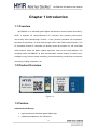

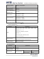


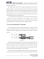

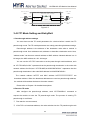

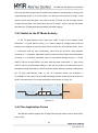


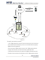


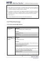


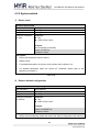
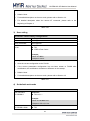
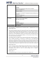
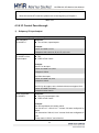
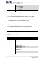
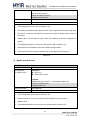

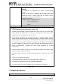


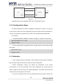


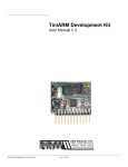


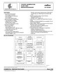


![Service Manual FCB Pinnacle 2 and 4 Flavor [ 005271 ]](http://vs1.manualzilla.com/store/data/006038828_1-2ffb9d6cd82d544c3f733521619945ce-150x150.png)