1
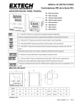
VT26 SERIES CONTROLLERS (VERSION 0.0) FUZZY ENHANCED PID INSTRUCTION MANUAL Table of Contents 1. INTRODUCTION .......................................................................................................................2 2. IN A HURRY ? .............................................................................................................................2 3. INSTALLATION .........................................................................................................................3 3.1.PANELMOUNTING ......................................................................................................................................... 3 3.2.CONNECTION AND WIRING........................................................................................................................ 3 4. FRONT PANEL DESCRIPTION...............................................................................................5 4.1. CONTROLLER FACE INDICATIONS ......................................................................................................... 5 DISPLAY AND INDICATOR ........................................................................................................................ 5 PV (PROCESS VALUE) DISPLAY .............................................................................................................. 5 SV (SET VALUE) DISPLAY ......................................................................................................................... 5 4.2. KEY FUNCTION ....................................................................................................................................................................................... 5 5. CONFIGURATION AND PARAMETER SETTINGS ............................................................6 5.1. USER LEVEL ................................................................................................................................................. 6 5.2. SOFT LEVEL ................................................................................................................................................. 7 5.3. PID LEVEL ..................................................................................................................................................... 7 5.4. OPTION LEVEL ............................................................................................................................................. 8 5.5. SCALING FOR LINEAR INPUT ................................................................................................................ 10 6. OPERATION .............................................................................................................................10 6.1. HOW TO CHANGE THE INPUT TYPE .................................................................................................... 10 6.2. TUNING YOUR VT26 CONTROLLER (AUTO TUNING)..................................................................... 10 6.3. TUNING THE CONTROLLER MANUALLY ............................................................................................ 12 6.4. MANUAL CONTROL .................................................................................................................................. 13 6.5. ALARM FUNCTIONS ................................................................................................................................. 13 6.6. ALARM MODES .......................................................................................................................................... 14 6.7. HEAT / COOL USING THE ALARM ......................................................................................................... 14 6.8. REMOTE SETPOINT USER INFORMATION. ...................................................................................... 15 6.9. USING THE ALARM IN A RAMP AND SOAK FUNCTION. ................................................................ 16 7. PROGRAMMING LEVEL PARAMETERS ..........................................................................17 8. ERROR MESSAGES AND TROUBLESHOOTING ............................................................18 9. SPECIFICATIONS ....................................................................................................................18 VT26 MANUAL QIS 2 V6 1 1. INTRODUCTION This manual contains information for the installation, operation and tuning of your Vertex VT26 series FUZZY ENHANCED auto-tuning microprocessor based controller. These controllers carry a two-year factory warranty. The VERTEX microprocessor controllers are FUZZY ENHANCED “proportional + integral + derivative” (PID) controllers that come in a variety of standard DIN sizes. The input is configurable and allows selection of inputs between thermocouples and RTD’s. You can also have 4~20 and other linear inputs as an option to be specified when ordering the controller. When ordering your controller you can choose between Relay, SSR, Heat / Cool, 4~20 mA or other output signals. They have dual displays that show the input (measured temperature) in the top digital display and the required set point in the lower. They all come standard with 2 alarm relay outputs. The controller boasts a comprehensive range of other features that include a ramp, soft start with power limiting, auto/manual function and comes standard with two configurable alarms. The controllers can be switched to manual and can work as “time based ratio out-put controllers” in the event of thermocouple or input failures taking place. There are other options you can choose including “retransmission” of either the PV or SV or RS485 communications. We have a simple data package (software) that you can use free of charge to link to and monitor or record data. 2. IN A HURRY ? Vertex temperature controllers, although quiet sophisticated, can be very simple to use as well. In it’s simplest form, all you need to do is install it and get the wiring right, (YOU MUST READ CONNECTIONS AND WIRING section 3.3, 3.4 + 3.5 BELOW) turn it on, check that the thermocouple type it is correct, (during the self test it will display the input type), make sure it is reading more or less the right temperature, that the heating elements actually get hot when the “C1” light is on and away you go. No need for laboriously reading this manual and changing and setting all the parameters….Just turn it on and when the system it is controlling has reached it’s operating temperature, do an “auto-tune” as explained in the section “Tuning your VERTEX VT26 series controller” You can also however explore all the parameters and set and use it in any way you may wish. If you are not sure please contact Vertex and ask, we are always happy to help. VT26 MANUAL QIS 2 V6 2 3. INSTALLATION 3.1. PANEL MOUNTING The panel cut out sizes are shown below Panel Cutout A B Model A B C D E a b c d VT-4826 48 48 6 100 45 45+0.5 45+0.5 60 48 VT-4926 48 96 9 80 91 45+0.5 92+0.5 120 48 VT-7226 72 72 9 80 67 68+0.5 68+0.5 90 72 VT-9426 96 48 9 80 45 92+0.5 45+0.5 48 120 VT-9626 96 96 10 80 91 92+0.5 92+0.5 120 96 (Unit:mm) 3.2. CONNECTION AND WIRING VT26 MANUAL QIS 2 V6 3 BEFORE WIRING PLEASE CHECK THE LABLE FOR CORRECT MODEL AND OPTIONS. Connections Explained These are typical input connection drawing intended to explain the schematic symbols: Now lets look at the detail included here…… RTD Input looks like this Thermocouple input like this mA or mV looks like this 3.3. Mains Power Input The controller can operate on any voltage between 90 ~ 264 VDC or VAC, 50/60 Hz. Power should be protected by a 2 amp fuse or 1 amp circuit breaker. As an optional extra you can have 24 V AC or DC. (Will work between 18 V and 36 V) Please be sure to order your controller with this option should it be required. Note that the mains power terminals are T1 + T2 on the VT4826 and on T19 + T20 for the VT9626 and VT4926. 3.4. Sensor input This controller has selectable input making it possible to select any thermocouple or PT100 in the setup parameters from the face buttons. Do not run sensor cables adjacent to power carrying conductors as signal interference can take place and distort the input. The correct type of thermocouple extension lead wire or compensating cable must be used when using thermocouples. Ensure that the polarities of the thermocouple wires are correctly connected. The terminals used for the probe (thermocouple or PT100) are, VT4826 …T7, T8 + T9 (T/C on T7 + T8) and for the VT9626 and VT4926, T8, T9 + T10 (T/C on T9 + T10) 3.5. Controller outputs: The controller can have any one of the following output types. Be sure to check which one you require when ordering. Available outputs are Relay output (10A/240VAC) This functions as a simple potential free switch. VT4826 use T11 + T12. VT4926 and VT9626 use T17 + T18 Solid State Relay output. (24Vdc pulsed) This supplies a 24 Vdc signal to switch SSR‟s requiring a DC 3 ~ 32 Vdc control signal. VT4826 use T11 (-ve) + T12 (+ve). VT4926 and VT9626 use T17 (+ve) + T18 (-ve) Milli-amp output (4 ~ 20 mA). Max load 600 ohms This supplies a 24Vdc driven 4~20 or 0~20 signal. VT4826 use T11 (-ve) + T12 (+ve). VT4926 and VT9626 use T17 (+ve) + T18 (-ve) 1 ~ 50mV, 1 ~ 5V, 0 ~ 10V also available as an option. VT26 MANUAL QIS 2 V6 4 4. FRONT PANEL DESCRIPTION 4.1. Controller Face indications DISPLAY AND INDICATOR PV (Process Value) Display Displays the actual measurement of the input. Displays the parameter index code when selected. Displays the error message. SV (Set Value) Display Displays the set value. (Required Setpoint) Displays the parameter data when selected. Displays the output percentage value when selected. A1 status LED indicator (Alarm 1 relay status LED) This LED is lit in red when the alarm 1 relay is active. A2 status LED indicator (Alarm 2 relay status LED) This LED is lit in red when the alarm 2 relay is active C1 status LED indicator (Main output 1 status LED) Illuminates in green when the control output 1 is active. C2 status LED indicator (Control output 2 status LED) Illuminates in green when the control output 2 is active. AT status indicator When the controller is auto tuning the rightmost lower decimal point in the PV display will blink. Auto tuning may take from several minutes to several hours depending upon the process in question. MA status indicator When the manual control mode is selected. The rightmost decimal on SV display will blink. 4.2. KEY FUNCTION SET key Press once to access the next configurable parameter within the level you are in. Press for 5 seconds to reset alarm timer if used. SHIFT key Shift digits to be adjusted by up/down key. DOWN key Press to decrease the set point or parameter value. VT26 MANUAL QIS 2 V6 5 UP key Press to increase the set point or parameter value. Press the SET and UP keys once to return the normal operation. LEVEL key Press the SET and SHIFT keys simultaneously for 5 seconds and then use the up and down keys to select the programming level required. (ie: User, Soft, PID etc) Now press the SET key to enter that particular level and access the first parameter. Display Engineering Unit for analog input setting. Press the UP and DOWN keys simultaneously for 5 seconds to access “LnLo” and “LnHi” parameters. These values are used to set the display engineering units you require to correspond to the analog input being used. Eg: a 4 ~ 20 input may represent 0 ~ 100 ºC or any other range you chose. NOTE: IT IS POSSIBLE TO REMOVE OR RE-ARRANGE THE PARAMETERS DISPLAYED IN THE “USER” AND “PID” LEVELS. IF YOU ARE AN INSTRUMENTATION ENGINEER AND HAVE AN INSTRUMENTATION SOLDERING IRON AND SOLDER SUCKER PLEASE CONTACT US FOR DETAILS ON HOW TO DO THIS. 5. CONFIGURATION AND PARAMETER SETTINGS All configurable parameters are user friendly and clearly structured in three levels. To change level from one to the next, please press keys for at least 5 seconds to access level selection. Use UP/DOWN key to select programming level. 5.1. Soft Pid level. ( Option level. ( Scaling for Linear Input ) ) USER LEVEL The following parameters are listed in a default sequence. However any unused parameter can be removed and the display sequence is configurable to simplify the operation. : Set point value required for control. : Alarm 1 set point value in ºC. This will be a time set value while A1FU is set to T.on or T. off and the unit will be HH.MM or MM.SS depending on the choice of unit defined by the “P.tnE” parameter. Range -1999 - 9999 / 00.00~99.59 : Alarm 2 set point value in ºC. This will be a time set value while A2FU is set to T.on or T. off and the unit will be HH.MM or MM.SS depending on the choice of unit defined by the “P.tnE” parameter. Range -1999 - 9999 / 00.00~99.59 : Auto tune. Used to set Pb,ti,td (PID) parameters automatically using the auto tuning process. This procedure will also tune the “cooling” PID parameters as well if your controller has that option installed. : Auto tuning is disabled. VT26 MANUAL QIS 2 V6 6 : Most commonly used auto tuning procedure. The PV is compared with SV during auto tuning. : Used when you do not wish the PV (measured temperature) to exceed the SV during auto tuning. The process of auto tuning is done at 10% below the set value. : Hand (manual) control. Used to enable or disable the manual mode. Care must be taken when using this function as the output is set manually by the operator, and the controller will not make any automatic corrections should there be overshoot above the set value temperature. : Disable the manual mode : Enable the manual mode. : Output percentage. Indicating the % output set either by hand in manual or by the controller when controlling normally. : Auto tune. Used to set Pb,ti,td (PID) parameters automatically using the auto tuning process. This procedure will also tune the “cooling” PID parameters as well if your controller has that option installed. 5.2. SOFT LEVEL (Please note in order to unlock the soft level the lock parameter must be set to 0101) : The ramp can be used separately from the “Soft Start” or in conjunction with as you please. With the Ramp value set to 0 the ramp is disabled. When a value has been set in ℃/min each time a setpoint change is made the setpoint will ramp at the set rate from the original value to the new setpoint value. This can be set between the range of 0 ~ 9999 ℃/min (0.0 – 999.9) : This is the temperature setpoint below which at startup, the output will be limited to the % value set in the “out” parameter below. This value can be set anywhere between the LoLt - HiLt values of the range. :Output percentage value to which the output will be limited at startup until the temperature has reached the S.SP setpoint above at which the output will revert to full PID regulation. 5.3. PID LEVEL : Proportional band value. Setting range from 0.0 to 300.0 % of controller„s Span. set to 0.0 for on/off control. This value is automatically calculated by activating the auto tune function. It can also be set manually by the user if so desired. Ti : Integral (reset) time. This value is automatically calculated by activating the auto tune function. It can also be set manually by the user if so desired. When PB = 0.0, this parameter will be not available. When Ti is set to zero, make Pb & td ≠0 for PD control. : Derivative (rate) time. This value is automatically calculated by activating the auto tune function. It can also be set manually by the user if so desired. When PB=0.0, this parameter will be not available. When td is set to zero, Pb & ti ≠ 0 for PI control. : Cycle time for the main control output. Setting range is from 0 to 100 seconds. Set to 1 for SSR output, set to 0 for 4 ~ 20 mA analog output and set to 15 for relay or contactor. : Proportional band value for cooling control output when fitted. Set 0.0 for ON/OFF control. : Integral time for cooling control output. When PB=0.0, this parameter will be not available. When set to zero, Pb & td ≠ 0 for PD control. : Derivative time for cooling control output. When Pb=0.0, this parameter will be not available. When set to zero, VT26 MANUAL QIS 2 V6 7 Pb & ti ≠ 0 for PI control. : Cycle time of second control output. / : Hysteresis (Dead Band) for on/off control on output 1 and output 2. Users can create a dead band around the setpoint from 0.0 to 200.0 deg C. The temperature will continue to heat and rise above the setpoint by the “HyS1” amount set, then cool until it has dropped below the setpoint by the same amount before switching on again. / : Hysteresis for alarm 1 and alarm 2. The setting range is 0.0 to 200.0 and it works in the same way as for the main Hysteresis setting. : Dead band value. This defines the dead band between the heating and cooling outputs when used and can be set from -100.0 to 100.0 deg C. If you are using proportional or PID control even though you set a dead band you may get overlapping switching between the heating and cooling. This is a result of the control algorithm action. If you make both the heating and cooling Pb = 0 however it will ensure that there is nothing on between the two. : Set point offset. Setting range is from -100.0 to 100.0 or –1000 to 1000. This value will be added to SV to perform control. It mainly used to eliminate offset error between the SV and PV that may be experienced during proportional only control. : Process value offset. Setting range form -100.0 to 200.0 or –1000 to 2000 This parameter allows for manual compensation of any process off-set that may exist between the measurement of the probe and the reading on the controller PV display.. : Parameter lock. This security feature locks out selected levels or single parameters prohibiting tampering and inadvertent programming changes. To change any “Lock” settings you must first make sure that gap “G1” is soldered. Table 3-1 Parameter lock selection Setting Description 0000 All parameters are locked out. 0001 Only SP is adjustable 0010 Only USER level is adjustable 0011 USER and PID levels are adjustable. 0100 USER, PID, OPTI levels are adjustable. 0101 USER,SOFT,PID,OPTI levels are adjustable. 0101~0111 1000 ~ 1111 5.4. All parameters in all levels are opened. 1000=0000, 1001=0001, 1010=0010, 1011=0011, 1100=0100 but Output 2 is opened. OPTION LEVEL : Sensor input selection. Table 3-2 Input and range VT26 MANUAL QIS 2 V6 8 TYPE DISPLAY RANGE J -50℃~1000℃ -58℉~ 1832℉ K -50℃~1370℃ -58℉~2498℉ T -270℃~400℃ E -50℃~1000℃ -58℉~1832℉ B 0℃~1800℃ 32℉~3272℉ R -50℃~1750℃ -58℉~3182℉ S -50℃~1750℃ -58℉~3182℉ N -50℃~1300℃ -58℉~2372℉ C -50℃~1800℃ -58℉~3272℉ DPT -200℃~850℃ -328℉~1652℉ JPT -200℃~600℃ -328℉~1112℉ LINEAR -1999~9999 -454 ℉ ~752 ℉ : Unit of measure selection. : Degrees C. : Degrees F. : Engineering unit. Only for linear input. : Decimal point selection. : No decimal point. : 0.1 resolution. : 0.01 resolution. Only for linear input. : 0.001 resolution. Only for linear input. After reconfiguring the decimal point, please reconfirm other parameter settings that may be effected. : Output 1 control action. : Reverse action. Used for heating control. : Direct action. Used for cooling control. : Low limit of span or range. Set the low limit lower than the lowest expected SV and PV display. Normally set at 0 deg C. If you make this setting above 0 deg C when the controller PV drops below this setting it will be out of range and cease to operate. : High limit of span or range. Note: If you have a PV retransmission output the Hilt and Lolt sets the range that will equal your retransmission signal. Ie: 0~1000 / 4~20 mA or whatever. : Software filters. / : Alarm function selection. See section 5.1 for detail. / : Alarm mode selection. See section 5.2 for detail. : Address of the controller when communicating with a master device using RS485 comms. Communication baud rate. 2.4k=2400 bps, 4.8k=4800 bps, 9.6k=9600 bps, 19.2k=19200 bps VT26 MANUAL QIS 2 V6 9 5.5. SCALING FOR LINEAR INPUT Press the UP and DOWN keys simultaneously for 5 seconds to access “LnLo” parameter. Adjust “LnLo” setting to correspond the low scale and after adjustment press key once to access “LnHi” Parameter Adjust “LnHi” setting to correspond the high scale and after adjustment press key once for normal operation 6. OPERATION 6.1. HOW TO CHANGE THE INPUT TYPE Press the SET and SHIFT keys simultaneously for 5 seconds until the display reads Level in the top display. Then use the up and down keys to select the programming level required. (ie: User, Soft, PID etc) In this case choose the Opti level. Now press the SET key to enter that particular level and access the first parameter. This should be the Type parameter. Use the up and down key to select the input type you wish to have as listed in the table below TYPE DISPLAY RANGE J -50 ~1000 -58 ~ 1832 K -50 ~1370 -58 ~2498 T -270 E -50 -454 ~400 ~1000 ~752 -58 ~1832 B 0 32 ~3272 R -50 ~1750 -58 ~3182 S -50 ~1750 -58 ~3182 -58 ~2372 -58 ~3272 ~1800 N -50 ~1300 C -50 ~1800 DPT -200 ~850 -328 JPT -200 ~600 -328 LINEAR ~1652 ~1112 -1999~9999 Now press the SET key a few times until you reach the Press the SET key again and you will see the parameter and leave this set at 0000 . . Use the up and down to make this the nearest 100‟s setting suitable. (ie a range of 0~200 or 0~400 or 0~600 etc etc) Now 6.2. Press the SET and UP keys once to return the normal operation. TUNING YOUR VT26 CONTROLLER (Auto Tuning) Tuning is the process of setting the Proportional, Integral and Derivative terms of the controllers main output VT26 MANUAL QIS 2 V6 10 to best suit your application and give the best possible control under your specific circumstances. (Note this tuning will also tune the second cooling output should your controller have this option) If you are not happy with the stability of control, and wish to have less over and undershoot around the setpoint, it is advisable to do this procedure. It is also advisable always do this on commissioning new installations. The auto tune function is used to “teach” the controller the main characteristics of the process. It “learns” by cycling the output on and off around the setpoint. The results are measure and used to calculate optimum Pb, ti, td values, which are automatically entered into nonvolatile memory. The auto tune function is triggered manually and can be used during setup of the controller. 1. Firstly install the controller and get it controlling using the factory settings (As supplied) 2. Always set the setpoint at about half the eventual control temperature the first time you turn it on after installing it during commissioning. This will allow the controller to start controlling and you will easily see if there is something wrong. 3. If the controller is being used as a PID controller, the output will be on and stay on at first, and the temperature will rise towards the setpoint. As it nears the setpoint it will begin to switch on and off. You can monitor this by watching the “C1” light on the display. When the output is on and it is heating, the light will be on. 4. Once the controller has stabilized at that setpoint and is working more or less ok, take the setpoint up to the required temperature and let it re-stabilized there. 5. If you are then not happy with the control results you can make the controller set (tune) the PID parameters itself. Should you wish to do this instruct the controller to do an “auto-tuning” calibration of the parameters. 6. Make sure that the value of Pb is not zero (Pb = 0 forces on/off control). Set the “ to “ ” . (“ ” parameter ” will force the tuning process at 10% below the required setpoint and is not generally used.) The rightmost decimal (AT) on the PV display will blink during tuning process. (See explanation of difference between “ 7. ” and ” below) After two oscillatory cycles of on/off control action around the setpoint (SV) the controller will use the measurements learned to set the PID parameters. The controller performs PID control with these “learned” PID values to verify the results. Finally the PID values will be entered into the memory. The controller will now start controlling using fuzzy enhanced PID control. 8. To abort an auto tune process. Simply set the “ ” parameter to “ ”. 9. If initially the controller is oscillating badly you may need to perform this procedure a second time to get the best results. 10. DO NOT CHANGE ANYTHING AT ALL IN THE PROCESS OR CONTROLLER WHILE DOING AN AUTO TUNING PROCESS. 11. Do not change anything during this procedure, as it will result in erroneous settings that may not control well at all. (Just leave the system for a few minutes while it does its thing.) 12. Also only do this at the full-required temperature, once the whole system has had a chance to warm up and work for a while. 13. Once it has finished the auto tune light will stop flashing and the controller will start to control using the new parameters. 14. Once this process is completed, you should get good control. It should really only be done once more when the system is in full operation (i.e. under normal working conditions with the process in VT26 MANUAL QIS 2 V6 11 full swing) if you are not happy with the control results. 15. When doing this on a barrel of an extrusion machine, or on a mould where there is more than one temperature being controlled in close proximity to another, where they may interfere with each other, always let them all stabilize and then choose the most stable zone and do that one first. Only ever do one zone at a time, let it finish and then do the next most stable zone next to the one you have already done. The controller can also be set to ON/OFF, PI, PD and P control mode. Set Pb = 0 for ON/OFF control mode. Set ti = 0 for PD control mode. Set td = 0 fro PI control mode and ti, td = 0 fro P control mode. The Hysteresis (dead band) 0f ON/OFF control can be set as follow: ON OFF ▲ SP-HYST SP+HYST SP When the second control output (output 2 cooling) is fitted it will behave as shown below. Bear in mind that when using Proportional or PID control there may be an overlap between the heating and cooling depending on the auto PID algorithm calculations. This is perfectly normal. You can make both heating and cooling proportional band = 0 then it will ensure that between the two nothing is switched on. Output Heating Cooling PV Overlap Band 6.3. Dead Band TUNING THE CONTROLLER MANUALLY To ensure that all parameters are configured correctly. Set “ Set the controller„s set point (SV) to a value, which closely approximates your application. The controller will perform the on/off control action. So the process value will oscillate about the set point. The following parameters should be noted: .1. ” to zero. Set “ ” to smallest. The peak-to-peak variation (P) in ℃/℉ (i.e. the difference between the highest value of the overshoot and the VT26 MANUAL QIS 2 V6 12 lowest value of the undershoot). .2. The cycle time of the oscillation in seconds. The control setting should be then calculated as follows: Pb= (P×100)÷Span ( %) ti = T td = T/4 Note: The span is the difference between the “ ” high limit value and “ ” low limit value. The PID parameters determined by the above procedures are just rough values. If the control results are unsatisfactory. The following rules may be used to further adjust the PID parameters. Adjustment sequence Symptom 1. Proportional Band 2. Integral Time 3. Derivative Time 6.4. Solution Slow response. Decrease PB. High overshoot or Oscillations Increase PB. Slow response Decrease ti. Instability or Oscillations Increase ti. Slow response or Oscillations Decrease td. High overshoot Increase td. MANUAL CONTROL Manual control allows the user to manually force the output percentage from 0.0 through 100.0% (usually used for testing purposes). To access the manual control mode, set the “ decimal (MA) on SV display will flash. Then the ” “ parameter to ”yes”, the rightmost “ parameter will display alternately ” “ and process value. The output percentage then can be adjusted by using up or down key to increase or decrease the temperature. To abort the manual control just simply set the ” “ to ” “. BE AWARE THAT THE CONTROLLER CANNOT MAKE ANY CORRECTIONS SHOULD THE TEMPERATURE GET TOO HOT WHILE YOU HAVE IT IN MANUAL MODE. 6.5. ALARM FUNCTIONS There are two independent alarm outputs available in VT20 series controllers. Each alarm can be set to function in one of six alarm function modes below. (Process high, process low, deviation high, deviation low, band high and band low) for or . When the alarm output is not used, set to “ ” to prevent unwanted alarm action. VT26 MANUAL QIS 2 V6 13 A1FU/A2FU ALARM TYPE ALARM OUTPUT OPERATION Alarm function OFF Output OFF Process high alarm. This alarm will turn on when PV = SP and stay on while it is above SV Process low alarm. This alarm will turn on below SV and stay on while PV is below ▲ SP PV ▲ PV ▲ SP+ALSP PV SP Deviation high alarm Deviation low alarm ▲ SP+ALSP Band high alarm OFF ▲ ▲ ▲ PV SP-ALSP SP SP+ALSP Band low alarm OFF OFF ▲ ▲ ▲ PV SP-ALSP SP SP+ALSP On-timer Off-timer 6.6. PV ALSP ▲ ▲ SP PV ALSP ▲ ▲ SP PV ALARM MODES 6.6.1.Special alarm features can be set using 6.6.2. : No special mode 6.6.3. : Standby mode and . 6.6.4.When selected, in any alarm function, prevents an alarm on power up. The alarm is enabled only when the process value reaches set point. Also known as “Startup inhibit” and is useful for avoiding alarm trips during startup. 6.6.5. : Latch mode 6.6.6.When selected, the alarm output and indicator latch as the alarm occurs. The alarm output and indicator will be energized even if the alarm condition has been cleared unless the power is shut off. 6.6.7. 6.7. : Standby and Latch mode HEAT / COOL USING THE ALARM 1. When it is required to have “Heat” and “Cooling” as for example on an extrusion barrel, you can use the alarm setting as the “cooling setpoint”. 2. The alarm based cooling will be on/off and not proportional. VT26 MANUAL QIS 2 V6 14 3. This in itself is not bad, as if you are cooling using a fan, or in other applications you may have compressor cooling, you cannot use proportional control, as switching a fan motor or compressor “on and off” rapidly will burn it out in any case. 4. In the case of liquid cooling (solenoid) on extrusion barrel zones, this method works just as well as proportional. 5. You can however have a second output (optional extra) that will provide full PID control on a second output and use it on a solenoid liquid cooling system should you so require. 6. When using the “alarm” for cooling, you can set the gap between the heating and cooling setpoints, and also specify how long the cooling must stay on each time it switches on using the “hysteresis” adjustment. 7. When using the alarm for cooling, the first thing to do is select the “Alarm Function” that links the alarm to the setpoint by a fixed “Gap”. That is Alarm Function “diF.H” (Deviation alarm high) selected in “oPt 1” level. The VT26 series controllers are supplied with this as a default setting. 8. This means that the Alarm setpoint will be linked to the main (Heating) setpoint by a gap as shown below. 9. When you move the main setpoint (Heating Setpoint) the Alarm (Cooling Setpoint) will follow, always offset by the gap. 10. Once you have selected this function you now set the gap. 11. This is done in Level 1 using the “A1Sp” setting. This will be the amount of degrees C that the Alarm Setpoint (Cooling Setpoint) will be above the Main Setpoint (Heating Setpoint) 12. You can now set the „Hysterisis” band attached to the alarm setpoint that will determine how long the cooling stays on each time it is switched on. 13. The temperature must rise to the alarm setpoint which in this case will be the main setpoint + the alarm 1 setpoint before the alarm (cooling) will switch on. 14. It will now stay on until the temperature has dropped below the lower limit of the hysteresis band before the cooling will switch off. 15. This setting is set in degrees C 6.8. REMOTE SETPOINT USER INFORMATION. 1. If your controller has been supplied with a remote setpoint you will only be able to change the setpoint via the remote input signal. VT26 MANUAL QIS 2 V6 15 2. 3. 4. 5. 6. You can however disable this input by following this procedure. Access the “ ” parameter in the PID level and change it to 1111. You will then be able to access the level to be found above the PID and Option levels. DO NOT CHANGE ANY OTHER PARAMETERS IN THE LEVEL AT ALL. Access the and change it from to SP-1 7. Go back to the PID level and reset the parameter to 0100. 8. The range of the remote setpoint is defined by the Lolt and HiLt values to be found in the Opti level. 9. Having disabled it once you will have to re-calibrate it if you try to re-activate the option. This will require a signal generator and a soldering iron and solder sucker. Contact your supplier for more information. 6.9. USING THE ALARM IN A RAMP AND SOAK FUNCTION. a. You can wire the main output through the “alarm 1” output and use the alarm in a timer function to control a “dwell” time after which the output will be cut off. b. Set the A1Fu to and set to (latch) c. Now check the parameter which allows you to choose between hours and minutes or minutes and seconds for the time setting when setting 6.10. Master Slave Options a. When choosing the Master Slave options you are choosing controllers that are pre-set to have the Master controller set point transmitted by RS485 comms to the slave units. b. Each slave unit will have the same setpoint as the master. c. This is useful when having a series of zones along which all set points should be the same. All you need to do is change the Master unit and all others follow. d. You can in fact use the Spof setting and create a profile all based on the master setpoint but in those with a Spof value being different by that amount. VT26 MANUAL QIS 2 V6 16 7. PROGRAMMING LEVEL PARAMETERS lst. Prog. Level 2nd. Prog. Level 3rd. Prog. Level th th 4 Prog. Level 5 . Prog. Level + 1. When 2nd Output (Cooling) is not selected, CPb、Cti、Ctd、 HYS2 and db parameters are not available. 2. When Pb≠0.0, HYS1 will be skipped. 3. When CPb≠0.0,HYS2 will be skipped. 4. When Pb=0.0,ti、td will be skipped. VT26 MANUAL 5. QISWhen 2 V6 CPb=0.0,Cti、Ctd will be skipped. 17 8. ERROR MESSAGES AND TROUBLESHOOTING Symptom Probable Solution -Input signal below the low limit -Set a higher value to high limit. -Incorrect input sensor selection -Check connect input sensor selection. -Input signal below the low limit -Set al lower value to low limit. -Incorrect input sensor selection -Check correct input sensor selection -Sensor break error -Replace sensor -Sensor not connected -Check the sensor is connected correctly -Unit must be repaired or replaced. -A/D converter damage -Check for outside source of damage such as transient voltage spikes. Keypad no function Process ”to a proper value -Keypads are locked -Set” -Keypads defective -Replace keypads value -Improper setting of Pb, Ti, Td -Start AT process to set Pb, Ti, Td automatically( Refer to 4.1) unstable and CT -Set Pb, Ti, Td manually( Refer to 4.2) -No heater power or fuse open No heat or output -Output device defective or incorrect output used -Check output wiring and fuse -Replace output device All LED‟s and display -No power to controller -Check power lines connection not light -Replace SMPS Process -SMPS failure Value changed abnormally Entered data lost -Electromagnetic (EMI) or Radio Interference -Suppress arcing contacts in system to eliminate high voltage Frequency spike sources. Separate sensor and controller wiring from “dirty” Interference (RFI) power lines. Ground heaters -Fail to enter data to EEPROM -Replace EEPROM 9. SPECIFICATIONS INPUT Thermocouple J, K, T, E, B, R, S, N, C TYPE RTD DIN PT-100; JIS PT-100 Linear 4~20mA; 0~50mV; 1~5V; 0~10V….. Range User configurable Accuracy ±1°C for thermocouple, ±0.2°C for RTD, ±3mA for Linear Cold Junction Compensation 0.1°C/°C ambient Sampling Time 0.25 sec. Normal Mode Rejection 60 dB Common Mode Rejection 120 dB CONTROL FUNCTION Proportional Band 0.0 ~ 300.0 % Integral Time 0 ~ 3600 sec. Derivative Time 0 ~ 900 sec. VT26 MANUAL QIS 2 V6 18 Hysteresis 0.0 ~ 200.0/ 0 ~ 2000 Cycle Time 0 ~ 100 sec. Control Action Direct (for cooling) or Reverse (for heating) OUTPUT Relay Contact Output 10A/240 VAC (Resistive Load) Pulsed Voltage Output Current Output 0 or 24 VDC (Resistive 250 ohms Min.) 4 ~ 20mA (Resistive 600 ohms Max.) Continuous Voltage Output 0 ~ 50mA, 1 ~ 5V, 0 ~ 10V…… (Resistive 600 ohms Min.) GENERAL Rated Voltage 90 ~ 264 VAC 50/60 Hz or VDC Consumption Less than 5 VA Memory Backup EEPROM and non-volatile memory (Approx. 10 years) Ambient Temperature 0 ~ 50°C Ambient Humidity 0 ~ 90% RH (Non-condensing) VT26 MANUAL QIS 2 V6 19