1
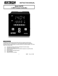
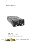
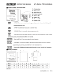
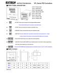
Instruction Manual
English / Español
Model 48VTR 1/16 DIN Process Controller
1. INTRODUCTION
The 48VTR is a microprocessor-based device which can compare a process input
(thermocouple, RTD, or analog input) to a user-programmable setpoint and adjust the
process (via relay or analog output), to bring the process to the desired setpoint. This ThreeMode PID controller offers:
Simultaneous Process Value (PV) and Setpoint Value (SV) display
Automatic alarm functions (11 in all)
Auto-Tuning automatically tailors the controller's response to a specific process
Security lock-out
Ramp-to-Setpoint and Soak functions
Input selectability
2. SPECIFICATIONS
2.1 General Specifications
Display
Status Indicators
LED display span
Indicating Accuracy
Sampling Time
Memory
Meter Enclosure
Front Panel
Power Supply
Power Consumption
Insulation Resistance
Noise Rejection
Operating Temperature / Humidity
Storage Temperature
Dimensions (Cutout)
Dual 7-segment 4-digit LED Displays: Red (PV),
Green (SV)
For Control output, Alarm output, Over range, AutoTune, and Open Input
-1999 to 9999 counts max (Programmable)
+0.2% Full Scale +1 digit
1 reading per 0.25 seconds
Nonvolatile type
ABS Plastic
Lexan (Drip and Dust Proof; IEC IP55, NEMA
Equivalent)
85 to 260VAC 50/60 Hz (automatic switching)
6 Watts
>50MΩ
Common Mode: 110 db typical; Normal Mode: 50 db
typical
o
o
14 to 122 F (-10 to 50 C); 90% RH max.
o
o
-4 to 140 F (-20 to 60 C)
1.77 x 1.77" ±0.02" (45.0 x 45.0mm ±0.5mm)
2.2 Input Specifications
Thermocouple input
(Programmable)
RTD input
Current input
Voltage input
Thermocouple Ranges
Type K
Type J
Type B
Type T
Type E
Type R
Type S
Type N
RTD PT100 input ranges
Linear input range
Temperature Stability
Repeatability
48VTR English
9/00
Types: J, K, T, E, B, R, S, N; Cold Junction Compensation
Thermocouple Break Protection: Upscale and Downscale
Lead Wire Effect: 0.015%/ohm (Input impedance: 10 megohm)
Pt 100 ohm (DIN, JIS); RTD Break Protection: Upscale and
Downscale
Lead Wire Effect: 0.015/ohm
(automatically compensates if one lead wire is < 5 Ω)
4-20mA DC (2.7Ω input impedance)
1-5V DC
o
o
-58 to 2498 F (-50 to 1370 C)
o
o
-58 to 1830 F (-50 to 1000 C)
o
o
32 to 3272 F (0 to 1800 C)
o
o
-454 to 752 F (-270 to 400 C)
o
o
-58 to 1382 F (-50 to 750 C)
o
o
32 to 3182 F (0 to 1750 C)
o
o
32 to 3182 F (0 to 1750 C)
o
o
-58 to 2372 F (-50 to 1300 C)
o
o
-392 to 932 F (-200 to 500 C); (DIN or JIS)
-1999 to 9999 display span (for 4-20mA, 1-5V, or special DC
input).
o
5uV/ C typical
o
o
0.83 C (Thermocouple); 0.2 C (RTD); 1 digit (Linear)
Ver. 2.7
1
2.3 Output Specifications
Control Output Relay
5 Amps @ 110V AC; SPDT (Resistive Load)
Control Output DC Voltage (Pulsed) 24V DC (DC drive for SSR)
ON: 24V DC typical, 29V DC max.
OFF: 0.3V DC max
Analog Control Output (Current)
4-20mA DC; Load limit: 600Ω max.
Alarm/Timer Types
High/Low Deviation/Absolute Alarms w/deadband
adjust plus Soak/Event Timers
Alarm Output Relay
3 Amps @ 110VAC; SPST (Resistive Load)
Output Control Modes
Proportional Band 0.0 to 100.0% of Full Scale (can be Auto Tuned)
Integral Time 0 to 3000 secs. (can be Auto Tuned)
Derivative Time 0 to 3000 secs. (can be Auto Tuned)
Cycle Time 1 to 100 secs. (0 sec for 4-20mA output)
Anti-Reset Wind-Up Inhibits integral action outside of the Prop. Band
Manual Reset 0 to 100% of Prop. Band
Hysteresis 0.0 to 25.5% of Full Scale
3. MOUNTING AND WIRING
3.1
3.2
3.3
3.4
3.5
3.6
Prepare a 1.77x1.77" ±0.02" (45x45mm
± 0.5mm) panel cutout The panel on
which the controller will be mounted
may be up to 0.4" (10mm) thick.
Remove the plastic mounting bracket.
Slide meter into panel through the
cutout.
Replace the mounting bracket and then
tighten the bracket screws. Do not
tighten the mounting screws
excessively.
Connect the power cord to the meter
but do not connect to power source
(refer to wiring diagram below).
Connect sensor input and control/alarm outputs (Fig.3)
Connect power to source.
Wiring Notes
AC Power: The AC supply terminals can handle 85 to 260VAC 50/60Hz without having
to be physically switched or specially configured.
Control relay: Terminals 8-9 are Normally Open (NO) and Terminals 8-10 are
Normally Closed (NC) when the controller is powered down or when the controller is
powered on and the relay is not active. Relays themselves DO NOT supply AC power.
AC Power must be wired to Relay terminals.
Alarm relay: Terminals 4-5 are Normally Open (NO) when controller is powered down
AND when it's powered-up in a non-alarm condition. Relays themselves DO NOT
supply AC power. AC Power must be wired to Relay terminals.
Inputs: Terminal 1 is negative and terminal 2 is positive for TC and Analog inputs. 3wire RTD use terminals 1-2-3 as shown. 2-wire and 4-wire RTD can also be used,
refer to Figure 3.
48VTR English
9/00
Ver. 2.7
2
Warning: An independent redundant alarm should be used if control/alarm
relay failure could result in potential harm or damage.
Control Output
AC
2-wire RTD
4-20
6
7
8+
9-
1
+
2
3
4
1
10
5
2
3
4-wire RTD
1
2
3
Short terminals 1 and 2
TC
Leave the 4th wire open
Analog
Alarm Output
RTD
Figure 3
4. METER DESCRIPTION
1.
Process Variable (PV) Display
2.
Setpoint Variable (SV) Display
3.
Control Output Status LED
4.
Alarm Status LED
5.
'Return' Programming Key
6.
Down Arrow Programming Key
7.
Up Arrow Programming Key
8.
'Scroll' Programming Key
9.
Auto Tune Decimal Indication
10.
Mounting Bracket
11.
Bracket Screw
5. FRONT PANEL DESCRIPTION
5.1 PV (Process Variable) Display LEDs
During normal operation, the top LED (red digits) displays the actual process
measurement (temperature, voltage, or current input signal). This process
measurement is known as the "Process Variable" or PV. In programming mode,
these red LEDs display the parameters from Programming Levels 1 through 4 (input
type, control action, etc.), one at a time. These parameters can be edited to suit the
user's requirements. Error messages are also displayed on these red LED Digits.
Programming details and error messages are explained later in this manual.
5.2 SV (Setpoint Variable) Display LEDs
During normal operation, the bottom LED (green) displays the user-programmable
Setpoint Variable (SV). This represents the desired process equilibrium point to
which the controller's output will adjust the process. To adjust the setpoint, use the
up/down arrow keys. The allowable setting range equals the range the user selects
in LoLt (Low Limit) and HiLt (High Limit) parameters during programming. While
programming, this green LED display shows the actual data that can be edited for
the parameter shown on the red LED display. For example if the red LED is
displaying input type, then the green LED lists the input types (J, K, Linear, etc.).
The user can then select the desired type using the programming keys. Refer to
later sections for more on programming.
48VTR English
9/00
Ver. 2.7
3
5.3 Status Indicators
'ALM' Status Indicator (Alarm Relay Status LED)
This LED is lit in red when the Alarm relay is active. Also, this LED flashes when
the Alarm is configured as an Event/Soak timer and is in the process of counting
down. Refer to Appendix A for more on Alarm Functions.
'OUT' Status Indicator (Control Output Status LED)
Illuminates in green when the control output is active.
AUTO TUNE Status Indicator
When the controller is auto tuning, the rightmost decimal on the green LED
display will blink on/off. When the meter is finished tuning, the decimal will cease
blinking and disappear. Auto Tuning may take from several minutes to several
hours depending upon the process in question. See section 9.2 for details on
Auto Tune.
LED Error Messages:
Err 1: A/D converter is inoperable. Unit must be repaired or replaced.
uuuu: Over range condition with regard to input signal.
nnnn: Under range condition with regard to input signal.
- - - - : Input sensor not connected or is inoperable.
5.4 Keypad Descriptions
SCROLL Key
Press once to access the programming mode’s first level. In programming mode,
move from one programmable parameter to the next by pressing the SCROLL
key. The SCROLL key is also used in combination with the RETURN key to move
between programming levels. The red LED display will show each parameter
title as you scroll through the list. Also, to activate an autotuning session, press
and hold the SCROLL key for 5 seconds.
UP Arrow Key
Increases the Setpoint (SV). Also increments parameter data when
programming.
DOWN Arrow Key
Decreases the Setpoint (SV). Also decrements parameter data when
programming.
RETURN KEY
During normal operation, pressing the RETURN key permits the user to view the
controller output action as a percentage (0.0-100.0%). Press this key from any
other mode to return to the normal SV display. The RETURN key is also used
with the SCROLL key (pressed simultaneously) to move from one programming
level to another.
48VTR English
9/00
Ver. 2.7
4
Table I - Programming Level Parameters (default values) at a glance
1st Prog. Level
2nd Prog. Level
RAmp (0.0)
Pb (0)
oPoF (0.0)
Ti (240)
A1SP or timE
Td (40)
Note: Symbols shown are similar to the
actual LED meter displays, which show
parameters in mixed case.
Some parameters may not appear
depending upon the setting in P-L
(Parameter Lock) in 3rd programming
level
* Default value is dependent on the type
of input or output installed in the device.
3rd Prog. Level
REmo (0)
P-L (4)
A1FU (2)
A1HY (0.1)
Act (1)
Unit (*)
Dp (*)
Ct (15)
HYST (0.1)
EroP (2)
Addr (0)
PvoF (0.0)
TYPe (*)
LoLt (0.0)
HiLt (500.0)
4th Prog. Level
LoCA (0.0)
HiCA 1000
TunE (1)
6. FIRST PROGRAMMING LEVEL PARAMETERS
Press the SCROLL key to enter this level. Then use the SCROLL key to move through
the parameter list. Use the ARROW keys to change the setting. To return to normal
operation at any time, press the RETURN key once.
Note: The configuration of the controller will dictate which parameters will appear. For
example, the 'ramp' parameter will not appear if Parameter Lock is set to a value
of '2' or ‘0’. Also, A1SP will not appear in the parameter list if parameter A1FU
(alarm function) is set to a value of 8,9,10, or 11.
rAmp:
Programmable rate of rise limit for PV. Permits the user to restrict the rate at
which the measured variable (PV) changes. Setting range: 0.0 to 100.0 units
per minute. Default = 0. The controller will monitor the changing PV and
override the controller output if necessary to limit the PV's rate of change.
oPoF:
Output Offset. "Manual reset" function. The user can program a value (0.0 to
100.0%) which will then be added to the controller output percentage. For
example, if the oPoF parameter is set to 10.0%, the controller's output
percentage will always be 10% higher.
A1SP:
Alarm Setpoint value. (Set the desired Alarm type in the A1Fu parameter,
refer to Appendix A for Alarm functions). Allowable setting range is limited by
parameter 'LoLt' and 'HiLt' (Low and High Limit) settings and the input type
selected. To lock out A1SP press the SCROLL and DOWN keys together for 4
seconds. Use same key-press to unlock A1SP.
timE:
Programmable duration for the Event/Soak Alarm Output Timers. The range is
0 to 9999 minutes. Refer to Section 13 and Appendix A for details on
Soak/Event Timer functions.
7. SECOND PROGRAMMING LEVEL PARAMETERS
Press and hold the SCROLL and RETURN keys simultaneously to enter this level from
the previous programming level. To return to normal operation at any time, press the
RETURN key.
NOTE: This is the Manual Tuning programming level. Rather than attempting a manual
tuning it is strongly recommended that AUTO TUNING be used to automatically set
these parameters. If PID Tuning is unfamiliar to you, manual tuning can cause
severe process disturbances. Try Auto Tuning first and then use Manual tuning
afterward to fine tune the parameters if desired. For the instructions on how to initiate
an Auto Tune session, refer to Sec. 11
48VTR English
9/00
Ver. 2.7
5
Pb:
Proportional band value. Setting range from 0.0 to 100.0% of controller's
Span. Default = 10.0. Set Pb to 0.0% for ON/OFF control action. This value
is automatically calculated by activating the AUTO TUNE function. If desired,
the user can later adjust this parameter to better suit the application.
ti:
Integral (Reset) value. 0 to 3000 seconds setting range. Default = 240. This
value is automatically calculated by activating the AUTO TUNE function. If
desired, the user can later adjust this parameter to better suit the application.
td:
Derivative (Rate) Time. 0 to 3000 seconds setting range. Default = 40. This
value is automatically calculated by activating the AUTO TUNE function. If
desired, the user can later adjust this parameter to better suit the application.
8. THIRD PROGRAMMING LEVEL PARAMETERS
Press and hold the SCROLL and RETURN keys simultaneously for 5 seconds to enter
this level from the second programming level. To return to normal operation at any time,
press the RETURN key.
rEmo:
Unused (must be set to ‘0’)
P-L:
Parameter Lock. This security feature locks out selected programming levels
or single parameters prohibiting tampering and inadvertent programming
changes. Depending upon setting, only certain Level 1 parameters display.
Setting
0
1
2
3
4
5
6
7
8
9
10
11
12
13
14
15
Parameter Lock-out effect
All parameters adjustable (Level 1 parameters: A1SP only)
Same as ‘0’ (level 1 parameters: Ramp and A1SP)
Same as ‘0’ (level 1 parameters: oPoF and A1SP)
Same as ‘0’ (level 1 parameters: Ramp, oPoF, and A1SP)
Same as '0', but level 4 is locked out
Same as '1', but level 4 is locked out
Same as '2', but level 4 is locked out
Same as '3', but level 4 is locked out
Same as '0', but levels 3 and 4 are locked out
Same as '1', but levels 3 and 4 are locked out
Same as '2', but levels 3 and 4 are locked out
Same as '3', but levels 3 and 4 are locked out
Same as '0', but levels 2, 3, and 4 are locked out
Same as '1', but levels 2, 3, and 4 are locked out
Same as '2', but levels 2, 3, and 4 are locked out
Same as '3', but levels 2, 3, and 4 are locked out
A1Fu:
Alarm Function. Select the desired Alarm or Timer function from the alarm
functions list in Appendix A.
A1HY:
Hysteresis for Alarm. The Setting range is 0.0 to 25.5% of the controller's
span settings. The controller's Span extends from the value programmed in
'LoLt' to the value programmed in the 'HiLt' parameter (Low and High Limits).
Hysteresis is used to eliminate relay "chatter" by creating a deadband that
extends from the alarm setpoint down or up (depending upon the alarm type)
where no relay action can occur. The larger the hysteresis value the less the
possibility of relay chatter.
Act:
Output control action. Set to "0" for cooling (direct) action or "1" for heating
(reverse) action.
unit:
Unit of measure selection. Program as follows:
degrees F
degrees C
Process inputs
0
1
2
48VTR English
9/00
Ver. 2.7
6
dP:
Decimal Point selection.
no decimal point
0.1 resolution
0.01 resolution (cannot use this setting for temperature inputs)
0.001 resolution (cannot use this setting for temperature inputs)
00
01
02
03
Ct:
Control Output Cycle Time. Range: 0 to 100 seconds. This is the period of
time the controller waits between output percentage changes. The longer the
time set here, the less responsive the controller will be to process changes.
Set Ct for the longest period of time possible without causing process
oscillations; this will help to prolong the life of the relay.
NOTE: Set ‘Ct’ to '0' seconds for the 4-20mA analog output option. Parameter
'Ct' is not used when ON/OFF control is activated.
Hyst:
Hysteresis for ON/OFF control output. Users can create a deadband region
from 0.0 to 25.5% of SPAN. The SPAN is the region that extends from the
user-programmable Low Limit (LoLt) value to the High limit (HiLt) value.
Hysteresis is used to eliminate control relay chatter by creating a deadband
that extends from the setpoint down or up (depending upon the relay's
function) where no relay action can occur.
EroP:
Error Protection. The desired state to which the Control and Alarm relay
outputs default in the event of controller error.
0
1
2
3
OFF
OFF
ON
ON
OFF
ON
OFF
ON
Addr:
Not used. Set to 0.
PVoF
PV Offset. Permits the user to offset the PV indication from the actual PV. For
o
example, if the thermocouple used is producing readings 2 higher than the
o
actual temperature across the range, the user can eliminate the 2 difference
by programming a "-2" value at this parameter. Overall range of the setting is 180 to +180. The default value is '0'.
tyPE: Sensor input selection. Select from the list below:
00
01
02
03
04
05
06
07
08
09
10
J type thermocouple
K type thermocouple
T type thermocouple
E type thermocouple
B type thermocouple
R type thermocouple
S type thermocouple
N type thermocouple
RTD Pt100 ohm (DIN)
RTD Pt100 ohm (JIS)
Linear mode (voltage or current input)
Note: The controller can be
ordered in one of four input types;
Thermocouple, RTD, Voltage or
Current.
Conversion from one input type to
another requires a hardware
modification. Contact Extech for
information.
LoLt:
Low limit (of Span or Range). Set the Low Limit lower than the lowest
expected SV and PV display. Note that the low limit is restricted to the limits
specified for the type of input selected.
HiLt:
High limit (of Span or Range). Set High Limit higher than the highest expected
SV and PV display. Note that the high limit is restricted to the specification for
the type of input selected.
48VTR English
9/00
Ver. 2.7
7
9. FOURTH PROGRAMMING LEVEL PARAMETERS
Press and hold the SCROLL and RETURN keys simultaneously for 5 seconds to enter
this level from the third programming level. To return to normal operation at any time,
press the RETURN key.
LoCA and HiCA: Low and High Input Calibration values. Refer to Section 10
“Calibration” for details.
tunE:
Auto Tuning ‘initialization mode’ selection. This parameter allows the user to
select when an Auto Tune session is automatically initiated by the controller.
Set this parameter as desired from the Table in Section 11.1. To activate Auto
Tune manually, refer to Section 11.2.
10. CALIBRATION
Important Note: Calibration is rarely required and special equipment is needed to
perform calibrations. The calibration procedure cannot be aborted once the calibration
parameters are fully accessed. Do not initiate the calibration process until fully prepared
th
and qualified to do so. It is safe to scroll through the 4 programming level to view the
setting. Follow these steps only if prepared to do so.
a.
"LoCA" (Low Calibration) will be the first parameter to appear in this level.
b.
Remove the sensor from the controller's input screw terminals and connect a
Thermocouple (mV) or RTD (resistance) simulator to the controller's input
terminals. For a process DC input, use a 4-20mA or 1-5VDC signal, depending on
the input type of the controller.
c.
Apply the low input signal to the controller which corresponds to the range you are
using, i.e., for 4-20 mA inputs, 4 mA would now be applied to the controller.
d.
Use the UP/DOWN arrow keys to set the value, which will display for a 4mA input.
For example, for a 4-20mA input to display –50 to +150, set ‘LoCA’ to –50.
e.
Press and hold the RETURN key for at least 5 seconds and the parameter on the
display will change from "LoCA" to "HiCA" (High Calibration). The Low Calibration
value is now written into the controller's non-volatile memory.
f.
Apply the high input signal to the controller, which corresponds, to the range you
are using. For example, for a 4-20mA input controller, apply a 20mA signal.
g.
Use the UP/DOWN arrow keys to set the value that will display for a 20mA input.
For example, for a 4-20mA input to display –50 to +150, set ‘HiCA’ to +150.
h.
Press and hold the RETURN key for at least 5 seconds and the meter will return to
normal operation. The High Calibration value is now written into the controller's
non-volatile memory.
i.
Input a signal midway between the Low and High Calibration signals previously
applied and verify that the display indicates a value midway between the high
display (+150, in the above example) and the low display value (-50). For the
example, apply 12mA to display +50.
11. AUTO TUNING
11.1 Auto Tune Initialization Modes
The Controller has the capability to start an Auto Tune session automatically. If this is
desired, select the conditions whereby an Auto Tune session will automatically begin
from Table III below. The controller defaults to Setting = ‘0’ (user initiates an Auto Tune
session). To manually initiate an Auto Tune session, follow the procedure in Section
11.2.
48VTR English
9/00
Ver. 2.7
8
Table III - Programmable Auto Tune Initialization Modes
0
1
2
3
4
5
Auto Tune ‘Initialization Modes’
Auto Tune can only be initiated manually with the SV not equal to the PV
Auto Tune can only be initiated manually with the PV equal to the SV.
Auto Tunes automatically when the controller is FIRST powered up if the PV < SV.
Auto Tunes automatically when the controller is FIRST powered up if the PV = SV.
EVERY time the controller is powered up the auto tune begins if the PV < SV
EVERY time the controller is powered up the auto begins automatically if the PV = SV
11.2 Auto Tune Procedure
a. In order to automatically set the Tuning parameters in Level 2 (‘Pb’ Proportional Band,
‘ti’ Integral time or Reset, and ‘td’ Derivative time or Rate), first adjust the controller's
setpoint (SV) to a value which closely approximates your application.
b. Make sure that the value for Proportional Band (Pb) is NOT zero (zero initializes
ON/OFF control).
c. Press and hold the SCROLL key for at least 5 seconds until the right-most decimal
point on the PV display begins flashing.
d. When Auto Tune is complete, the right-most decimal will cease flashing. The new
Tuning values will now be stored in nonvolatile memory. Adjustments can be made
manually if desired in programming level 2.
e. To abort an Auto Tune process, simply press and hold the SCROLL key again for 5
seconds until the decimal stops flashing.
NOTE: The Auto Tune process can last from several minutes up to several hours,
depending on each system’s parameters.
12. AUTOMATIC AND MANUAL OUTPUT CONTROL
12.1 Automatic Control
Automatic Control is the normal mode of controller operation and does not require
keystrokes or special menus to access. In automatic control mode the controller
automatically adjusts the control output percentage so that the PV = SV.
12.2 Manual Control
Manual control allows the user to manually drive the output percentage from 0.0
through 100.0% (usually used for testing purposes). To access the Manual Mode, you
must first unlock it. Press and hold the DOWN Arrow and RETURN keys until the
display blinks. The feature is now unlocked. Now, press and HOLD the RETURN key
for approximately 5 seconds. The controller's output percent automatically will appear
on the SV display preceded by an 'H" for Heating or a 'C' for Cooling (depending upon
how the action of the controller is configured under the parameter 'act'). The rightmost
decimal will flash while in Manual mode. To manually adjust the controller's output, use
the UP and DOWN arrow keys. To return to normal operation, press the RETURN key
again. To re-lock the feature, press and hold the UP Arrow and RETURN keys until the
display blinks.
48VTR English
9/00
Ver. 2.7
9
13. RAMP AND SOAK FUNCTIONS
The Extech 48VTR controller operates as a fixed setpoint controller. However, the
controller offers several advanced features which can enhance your application. These
include Ramp-to-Setpoint and Soak/Event Timers. Refer to the details below.
13.1 Ramp-to-Setpoint (‘rAmP’ Parameter)
To limit the rate at which the controller allows the process (PV) to move towards
setpoint (SV), enter a value in units per minute for the 'rAmP' parameter. The
programmable limit ranges from 0.0 to 100.0 units per minute. The controller will
automatically adjust its outputs to observe this limit. Setting this parameter to zero
defeats the Ramp-to-Setpoint function. The “rAmP” parameter will not appear if
“Parameter Lock” (P-L) is set to a “0” or “2”.
13.2 Soak Timer Function
The Soak Timer function allows the process to ramp to setpoint and remain (Soak) at
that setpoint for a user-programmable period of time. Set the "A1Fu" parameter to
either '10' (Soak ON-TIMER) or '11' (Soak OFF-TIMER) depending upon the application
(refer to Table IV in Appendix A for the difference between ON and OFF Timers). Set
the Soak time in parameter 'timE' in the First Programming Level. The Output and
Alarm Relays must be wired in series so that the Alarm relay can switch the control
o
relay at the appropriate times (refer to Fig. 4). For example, when a setpoint of 500 F is
reached, the Soak time (programmed by the user under parameter 'timE") begins to
countdown. After the desired Soak time has elapsed, the Alarm relay switches thereby
switching the Control relay circuit.
13.3 Event Timer Function
The Alarm relay can be
programmed to switch state at
desired times in a process. This
is accomplished by first setting
the alarm function in parameter
"A1Fu" to either an EVENT-ON
or EVENT-OFF timer (refer to
the function list and Table IV in
Appendix A for the difference
between ON and OFF Timers).
Next, select a countdown time
in parameter ‘timE’. The relay
timer will start counting down
when the PV equals the SV.
Meter Contacts
Control 8
Relay
9
Alarm
Relay
AC Power
4
Figure 4
Load
5
6
7
Wiring the Alarm and Control Relays in Series
For example, while maintaining a certain temperature for 4 hours, an event is to take
place 2 hours into the process. The Event, in this example, is the controller's alarm
relay activating a pump. To do this, set the alarm function to an EVENT-ON Timer
(selection 8) in parameter "A1Fu". Set the time to 120 minutes (2 hours) in parameter
"timE". When the controller is powered the alarm relay will be OFF, when the PV = SV
the relay remains OFF but the timer begins to countdown, and after 2 hours the relay
will turn ON permitting the process event to take place.
48VTR English
9/00
Ver. 2.7
10
14. CUSTOMER SERVICE
Extech offers complete repair and calibration services for all of the products we sell.
For periodic calibration, NIST certification or repair of any Extech product, call customer
service for details on services available. Extech recommends that calibration be
performed on an annual basis to ensure calibration integrity.
15. WARRANTY
EXTECH INSTRUMENTS CORPORATION warrants this instrument to be free of defects
in parts and workmanship for one year from date of shipment (a limited warranty may
apply on sensors and cables). If it should become necessary to return the instrument for
service during or beyond the warranty period, contact the Customer Service Department at
(781) 890-7440 ext. 210 for authorization. A Return Authorization (RA) number must be
issued before any product is returned to Extech. The sender is responsible for
shipping charges, freight, insurance and proper packaging to prevent damage in transit.
This warranty does not apply to defects resulting from action of the user such as misuse,
improper wiring, operation outside of specification, improper maintenance or repair, or
unauthorized modification. Extech specifically disclaims any implied warranties or
merchantability or fitness for a specific purpose and will not be liable for any direct,
indirect, incidental or consequential damages. Extech's total liability is limited to repair or
replacement of the product. The warranty set forth above is inclusive and no other
warranty, whether written or oral, is expressed or implied.
Copyright © 1999 Extech Instruments Corporation. All rights reserved
including the right of reproduction in whole or in part in any form.
APPENDICES
Appendix A: Alarm Mode Selections for parameter 'A1Fu'
'00' Deviation High Alarm: For the Deviation High Alarm, the value entered for the
"A1SP" parameter equals the amount the controller's HIGH alarm setpoint is offset
from the main controller setpoint. For example, if SV = 400 and A1SP = +10 then
o
the Limit Alarm relay will trip when the temperature reaches 410 . The Deviation
alarm setpoint tracks the main setpoint meaning that it changes as the main
setpoint changes always remaining a programmed number of units from the main
setpoint.
'01' Deviation Low Alarm: With the Alarm setup as a Deviation Low Alarm, the value
entered for the "A1SP" parameter equals the amount to which the controller's LOW
alarm setpoint is offset from the main controller setpoint. For example, if you
entered SV = 400 and A1SP = -10 then the Alarm relay will trip when the
o
temperature falls below 390 . The Deviation alarm setpoint tracks the main setpoint
meaning that it changes as the main setpoint changes always remaining a
programmed number of units from the main setpoint.
'02' Process High Alarm: Relay trips when the process (PV) exceeds the value
programmed at A1SP. Process alarms are fixed, absolute values and do not
change as the main control setpoint changes.
'03' Process Low Alarm: Relay trips when the process (PV) falls below the value
programmed at A1SP. Process alarms are fixed, absolute values and do not
change as the main control setpoint changes.
'04' Deviation High Alarm with Standby Sequence: Same as the Deviation High
Alarm but no relay action takes place until the process PV reaches the setpoint for
a second time. Also known as "Startup Inhibit" and is useful for avoiding alarm trips
during startup.
'05' Deviation Low Alarm with Standby Sequence: Same as the Deviation Low Alarm
but no relay action takes place until the process PV reaches the setpoint for a
second time. Also known as "Startup Inhibit" and is useful for avoiding alarm trips
during startup.
48VTR English
9/00
Ver. 2.7
11
'06' Process High Alarm with Standby Sequence: Same as the Process High Alarm
but no relay action takes place until the process PV reaches the setpoint for a
second time. Also known as "Startup Inhibit" and is useful for avoiding alarm trips
during startup.
'07' Process Low Alarm with Standby Sequence: Same as the Process Low Alarm
but no relay action takes place until the process PV reaches the setpoint for a
second time. Also known as "Startup Inhibit" and is useful for avoiding alarm trips
during startup.
'08' EVENT ON-Timer: Upon power-up the alarm is de-energized. When the PV = SV
the alarm relay remains de-energized. When the timer counts down to zero, then
the relay energizes. Set the timer at parameter 'time' in Programming Level 1. See
Table IV below.
'09' EVENT OFF-Timer: Upon power-up the alarm relay energizes. When the PV = SV
the alarm relay remains energized. When the timer counts down to zero, then the
relay de-energizes. Set the timer at parameter 'time' in Programming Level 1. See
Table IV below.
'10' SOAK ON-Timer: Upon power-up the alarm relay is de-energized. When the PV =
SV the alarm relay energizes. When the timer counts down to zero the relay deenergizes. Set the timer at parameter 'time' in Programming Level 1. See Table IV
below.
'11' SOAK OFF-Timer: Upon power-up the alarm relay energizes. When the PV = SV
the alarm relay de-energizes. When the timer counts down to zero the relay
energizes. Set the timer at parameter 'time' in Programming Level 1. See Table IV
below.
When PV=SV
Controller
A1FU
ALARM RELAY MODE
at Power-up
Timer Starts
Setting
EVENT ON-TIMER
OFF
OFF
8
EVENT OFF-TIMER
ON
ON
9
SOAK ON-TIMER
OFF
ON
10
SOAK OFF-TIMER
ON
OFF
11
Table IV - EVENT and SOAK Timer Relay States
ON = Alarm Relay energized OFF = Alarm Relay de-energized
After Timer
Counts Down
ON
OFF
OFF
ON
APPENDIX B - PROGRAMMING EXAMPLE
o
Application Example - Maintain an Oven Temperature of 500 F
The controller monitors the oven temperature via the thermocouple. The controller
o
compares the actual temperature (PV) to the desired temperature (500 setpoint SV) and
throttles the heater as
o
needed to maintain 500 F.
Alarm Annunciator
Figure 5
If the oven temperature
rises
too
high,
the
controller's alarm output
Alarm Output
can trigger an alert. The
alarm contact can also be
K Thermocouple input (Measures oven temp.)
used to switch on/off an
external device such as a
48VTR
cooling
fan.
In
this
Com pares oven
example, the alarm will
Oven
tem perature to
trigger an annunciator at
desired setpoint
o
600 F. To perform this
and adjusts heater
task, refer to the steps
below. The parameters not
listed below are either
Heater
Control Output
inconsequential
with
(Adjusts Heater)
regard to this example or
they will not appear on the controller display due to the controller configuration.
48VTR English
9/00
Ver. 2.7
12
Programming Level 1
o
A1SP (Alarm Setpoint): Set to 600 F. Temperature at which the alarm will switch on the
annunciator.
Tuning the Controller (Level 2 parameters)
The best plan of attack with tuning is running the Auto Tune utility. Auto Tune will
automatically program the controller to respond with little process oscillation around
setpoint and minimal overshoot on oven heat-up. Run the Auto Tune utility per section 11
in this manual. Running Auto Tune supersedes programming Level 2 parameters.
Programming Level 3
A1Fu (Alarm Function): Set to '2' which is an absolute process alarm, meaning that the
o
o
alarm is fixed. In this case the alarm will be fixed at 600 F. This 600 F value is
programmed above in Level 1.
A1HY (Alarm Hysteresis): Set to '0'. Hysteresis is similar to 'deadband'. A region
extending from the alarm setpoint up or down, depending upon the alarm type, where
no relay action can occur to eliminate relay chatter.
Act (Action): This is control output action. Set to '1' for heating.
o
unit: Set to '1' for F
dp (decimal point): Set to '0' for no decimal point
Ct (Cycle time): To start off with, set to approx. 6 seconds. This can be re-adjusted later
after the process is observed. Cycle time is the rate at which the controller will make
adjustments to the heater. Set for the longest time possible (to save relay life) without
causing process oscillations.
tYPe: Set to '1' for a K Type Thermocouple
o
o
LoLt and HiLt (Low Limit / High Limit): Set these to 0 and 1000 respectively (This is
the Range/Span limits setting).
Calibration (Level 4 parameters)
Calibration is rarely required. If calibration must be performed refer to Section 10 for
details or contact Extech.'
Tech Support Hotlines
781-890-7440 ext. 200
[email protected]
48VTR English
9/00
Ver. 2.7
13