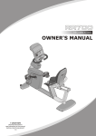
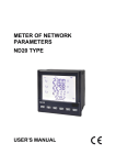
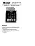
1
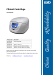
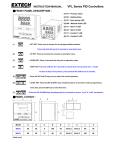
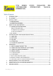
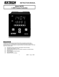
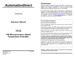
VERTEX VD SERIES
USER MANUAL
The Vertex VD series Temperature Controllers are a “Low Cost” Digital alternative to analog
controllers, designed for use in simple applications where three term (PID) control is not required. It
comes from the factory with default settings making it an “on/off” controller but can be user
configured to have proportional action “proportional”. It has a single digital display allowing access
to all the parameters including the “Process Variable” and “Set Point”. It is fully configurable on
input including PT100 (RTD).
There are three simple steps required to get you up and running:
1.
2.
3.
Installation
Wiring
Commissioning
Installation
Select the panel cut-out sizes from the table depending on the Model VD controller you have chosen
and install the controller accordingly in your panel.
■PANEL CUTOUT:
A
B
Model
A
B
C
D
E
a
b
c
d
VD-2000
48
48
6
100
45
45+0.5
45+0.5
60
48
VD-2001
72
72
9
80
67
68+0.5
68+0.5
90
72
VD-2002
48
96
9
80
91
45+0.5
92+0.5
120
48
VD-2003
96
48
9
80
45
92+0.5
45+0.5
48
120
VD-2004
96
96
10
80
91
92+0.5
92+0.5
120
96
(Unit:mm)
Wiring
■WIRING DIAGRAM:
Wiring Precautions:
Before wiring please check the model you are using and establish the correct terminals you should use,
by using this information and double checking it against the label on the label on the controller.
1
2
3
4
Mains Power:
1.1 You can use any mains voltage between 90 and 264 Volts AC (50 or 60 Hz) or DC
1.2 You can also order the controllers with a “Low Voltage DC” input that will accept anything
between 18 ~ 32 VDC for the mains power voltage.
1.3 The When using DC mains the input is not polarity sensitive
1.4 For Model VD2000 the mains voltage wiring goes on terminals 1 + 2
1.5 For Model VD2001 the mains voltage wiring goes on terminals 13 + 14
1.6 For Model VD2003/2004 the mains voltage wiring goes on terminals 19 + 20
Inputs will mostly be either thermocouple or RTD (PT100)
2.1 Firstly check on the box and case label to see if the controller you are installing is T/C
meaning thermocouple or PT100.
Thermocouples have two wires only.
3.1 Points to check are that the thermocouple is connected on the correct terminals.
3.2 For Model VD2000 this is terminals 7 + 8 with the thermocouple +ve wire on terminal 7 and
the –ve wire is on terminal 8.
3.3 For Model VD2001 this is terminals 6 + 7 with the thermocouple +ve wire on terminal 7 and
the –ve wire is on terminal 6.
3.4 For Model VD2003/2004 this is terminals 9 + 10 with the thermocouple +ve wire on terminal
10 and the –ve wire is on terminal 9.
3.5 If the temperature reads but responds in the reverse when testing, like when heating the
display goes down instead of up just swap these two wires around. This will not harm the
controller in any way if it is not correct.
PT100 (RTD) in most cases have three wires.
4.1 For Model VD2000 use terminals 7 + 8 + 9. The one color goes on terminal 7 and the two
wires with the same color go on terminals 8 + 9
4.2 For Model VD2001 use terminals 5 + 6 + 7. The one color goes on terminal 7 and the two
wires with the same color go on terminals 5 + 6
4.3 For Model VD2003/2004 use terminals 8 + 9 + 10. The one color goes on terminal 10 and
the two wires with the same color go on terminals 8 + 9.
4.4 If you are using a PT100 (RTD) with only two wires, one wire will go on the terminal where
the “one color” described above goes, and the other wire one on either of the other two
terminals used for PT100 inputs as described above and then you must bridge with a short
piece of wire between these two terminals that would have carried the same color wire as
described above.
5
6
7
Control outputs can be either “relay” or “SSR”
5.1 Please check carefully on the box and label on the side of the controller to make sure what
type of output your controller has. Incorrectly wiring this may blow the output and you will
be charged for repairing it.
5.2 All controllers are “Relay” output as factory standard. To have SSR you must especially
order them with this option.
Relay output....If you are using a relay output controller use the normally open contact
to switch the power going to the contactor. On the VD2000/2001 these terminals are 11 + 12,
VD2003/2004 terminals 17 + 18
6.1 Wiring this part of the circuit often involves other circuitry within the machine and someone
with general electrical knowledge should have a look at the circuit to decide how this should
be connected.
6.2 If you are replacing an old controller of a different make, carefully identify each wire on the
old controller and then substitute them in the correct position on the new VERTEX model.
6.3 Extreme care should be taken if attempting to do this as experience shows that most times
when it goes wrong it was a simple swapping of a wire or two that causes the problem.
6.4 Always take time up front and write everything down clearly before disconnecting anything
and take extreme care not to swap or confuse wires. This should be done by someone with a
good knowledge of electrical wiring circuits.
SSR output...If you are using a SSR output controller you would simply wire two wires from the
+ve and - ve output terminals directly to the corresponding polarity terminal on the SSR. For
Model VD2000 this will be terminals 11 (-ve) and 12 (+ve) and for Model VD2001 terminals 11
(-ve) and 12 (+ ve) and Model VD2003/2004 terminals 17 (+ve) and 18 (-ve)
7.1 If the controller is SSR output, it means the output signal is 24 Vdc. It is for use with SSR’s
that have a control signal input of 3 ~32 Vdc.
7.2 It will not work with SSR’s that have a control signal of 90~250 Vac.
7.3 If you have a SSR that works with 90~250 Vac you will need a relay output controller that
will simply switch the higher voltage signal feeding the Solid State Relay.
7.4 If you have any doubt at all consult your supplier who will assist in checking what exactly
you have or need.
Commissioning
Having correctly wired the unit you are now ready for the initial turn on.
1.
2.
3.
4.
5.
6.
7.
Turn the power on and watch the display as the controller self tests and powers up.
You will be able to see which thermocouple type the unit is set up for.
Once the power up is completed you will be looking at the measured temperature.
This parameter is identified by the small “PV” light, which will be on.
You can now check and set the set point you require.
You access this parameter by pressing either the up or down keys once.
The “SV” light will now be on and you will be looking at the set value, which you should now
set to about 70% of your final operating temperature.
8. You do this in order to watch the temperature rise to the setpoint at which point the output
identified by light “C1” must turn off.
9. Once the “C1” light is off there should be no power going to the heating elements and the
temperature should stop rising. Should this not happen you must turn off the power and
check your wiring.
10. The controller is supplied with a factory default making it an on/off controller. This means
that the temperature will rise up to the setpoint at which point it will switch off (“C1” off) and
then drop a little before the heating turns on again.
11. The controller is factory set with Pb=0 (on/off control mode). In this mode you can adjust a
deadband around the setpoint by changing the
parameter. It works like this, see Fig 1.
12. To Access the different levels, hold down the ‘SET’ key in for about 5 seconds.
ON
SP-HYST
▲
OFF
SP+HYST
■FRONT PANEL DESCRIPTION :
(1)PV
(2)SV
(3)C1
(4)A1
(5)A2
(6)A3
-
-
-
-
-
-
Process Value
Setting Value
Control LED
Alarm 1 LED
Alarm 2 LED
Alarm 3 LED
(1)
SET KEY. Press once to access the next programmable parameter.
(2)
UP KEY. Press to increase the set point or parameter value.
(3)
DOWN KEY. Press to decrease the set point or parameter value.
(4)
Press the SET and UP keys once to return the normal operation.
FIG1
■ PROGRAMMING LEVEL PARAMETERS
lst. Prog. Level
2nd. Prog. Level
3rd. Prog. Level
1.
When
=0.0 these
parameters will not appear, and
will be replaced by
.
2.
These parameters will
appear when
= t.on or t.Off.
and
will not be displayed.
(L=1~3, A1, A2,A3)
2.
These parameters will
appear when
= LinE and
will not be displayed.
FIRST PROGRAMMING LEVEL PARAMETERS
CODE
DESCRIPTION
Control set point value
RANGE
Default
LoLt - HiLt
100
Set point offset. This should always be left at 0 as any value here will
create an offset in control either above or below the “actual ” setpoint. It is -1000-1000
used as a “manual reset” when the controller is used in the proportional (-100.0-100.0)
control mode.
Process value offset. This should be left at 0 as any other value will cause
the PV display to read inaccurately by the amount either above or below the
-1000-2000
actual value. This is used in applications such as double boilers where the
PV reading is taken in a jacket and the product temperature may be a few (-100.0-200.0)
degrees lower.
Alarm 1 set point
Alarm 2 set point
-1999-9999
-1999-9999
Alarm 3 set point
-1999-9999
0
0
10
10
10
SECOND PROGRAMMING LEVEL PARAMETERS
CODE
DESCRIPTION
RANGE
Default
Proportional band. Set to 0.0 for ON/OFF control mode.
0.0-300.0%
0.0
Derivative (Rate). When
=0.0, this parameter will not appear.
0-900sec
60
Hysteresis for ON/OFF control on output. When
= 0.0 this
0-2000
2
parameter will not appear.
(0.0-200.0)
Proportional cycle time of control output. When Pb = 0.0 this
parameter will not appear. Set to 15 or 20 for relay output, Set to 1 or 2
for SSR output, Set to 0 for current output.
Hysteresis of alarm 1. When
= t.on or t.Off,
is not
displayed.
= t.on or t.Off,
is not
displayed.
= t.on or t.Off,
is not
displayed.
0
0-2000
0
0-2000
0
99 MM. 59 SS.
99HH. 59 MM.
=t.on or t.oFF(Alarm 3 action with delay time)
Parameter lock.
0-2000
99 MM. 59 SS.
99HH. 59 MM.
=t.on or t.oFF(Alarm 2 action with delay time)
Hysteresis of alarm 3. When
15
99 MM. 59 SS.
99 HH. 59MM.
=t.on or t.Off (Alarm 1 action with delay time)
Hysteresis of alarm 2. When
0-100sec
This security feature locks out selected levels or single
parameters prohibiting tampering and inadvertent programming changes.
0000
0001
0010
0011
0100
1000
1001
1010
All parameters are locked.
Only SP is adjustable.
USE (level) and A1(parameter) are adjustable.
USER、PID(level) and A1、A2(parameter) are adjustable.
USER、PID、OPTI(level) and A1、A2(parameter) are adjustable.
Additional A3(parameter). All parameter you can find out,but can’t
adjustable.
Additional A3(parameter),only SP is adjustable.
Additional A3(parameter). USER(level) and A1(parameter) are
adjustable.
USER、PID (level) and A1、A2、A3 (parameter) are adjustable.
1011
1100 All parameters in all level are opened.
THIRD PROGRAMMING LEVEL PARAMETERS
CODE
DESCRIPTION
RANGE
Default
Input type selection.
TYPE
RANGE(℃)
RANGE(℉)
J
K
T
E
B
R
S
-50 ~ 1000
-50 ~ 1370
-270 ~ 400
-50 ~ 1000
0 ~ 1800
-50 ~ 1750
-50 ~ 1750
-58 ~ 1832
-58 ~ 2498
-454 ~ 752
-58 ~ 1832
32 ~ 3272
-58 ~ 3182
-58 ~ 3182
N
-50 ~ 1300
-58 ~ 2372
Refer to figure.
K
-50 ~ 1800
-58 ~ 3272
-200 ~ 850
-328 ~ 1652
-200 ~ 600
-328 ~ 1112
-1999 ~ 9999
C
D-PT
J-PT
LINE
Unit of process value. The parameter is not displayed
:Degrees C.
when
:Degrees F.
=LinE
Used to limit the process value when linear input
(type=line) signal is out of range.
None= this function is not used.
Lo = The process value will be limited to LoLt when
input signal is lower than the scale range.
Hi = The process value will be limited to HiLt when
input signal is higher than the scale range.
Lo.Hi = The process value will be limit within the
range of LoLt to HiLt when input signal is out of scale.
Decimal Point selection.
℃
nonE,Lo
Hi,Hi.Lo
0000:No decimal point.
0000
000.0
00.00
0.000
000.0:0.1 resolution
00.00:0.01 resolution, used for linear input only.
0.000:0.001 resolution, used for linear input only.
0000
After changing the decimal point parameter please re-check
all the parameters.
:Reverse
Output control action.
action for
heating.
:Direct
action
for
cooling.
Low limit of span or range . Set the low limit lower
than the lowest expected SV and PV display.
High limit of span or range. Set the high limit higher
than highest expected SV and PV display.
Software filter.
Full range
0
Full range
500
0.00-100.0
5.0
nonE, Hi, Lo, dif.H,dif.L,
bd.Hi , bd.Lo, t.on, t.oFF
nonE, Stdy,
Alarm 1 mode. Refer to alarm mode section for detail.
Lath, St.La
HH.mm, mm.SS
nonE, Hi, Lo, dif.H,dif.L,
Alarm 2 function. Refer to alarm function section for detail
bd.Hi , bd.Lo, t.on, t.oFF
nonE, Stdy,
Alarm 2 mode. Refer to alarm mode section for detail.
Lath, St.La
HH.mm, mm.SS
nonE, Hi, Lo, dif.H,dif.L,
Alarm 3 function. Refer to alarm function section for detail
bd.Hi , bd.Lo, t.on, t.oFF
nonE, Stdy,
Alarm 3 mode. Refer to alarm mode section for detail.
Lath, St.La
HH.mm, mm.SS
RS485 address
0-255
Communication baud rate. 2.4k=2400bps, 4.8k=4800 bps,
2.4k, 4.8k,
9.6k=9600 bps, 19.2k=19200 bps
9.6k, 19.2k
Alarm 1 function. Refer to alarm function section for detail.
0
9.6k
ALARM TYPE SELECTION
A1FU/A2FU
ALARM TYPE
Alarm function OFF
ALARM OUTPUT OPERATION
Output OFF
PV high alarm
▲
SP
PV
PV low alarm
▲
SP
PV
Deviation high alarm
▲
SP+ALSP
Deviation low alarm
PV
▲
SP+ALSP
PV
OFF
Band high alarm
▲
SP-ALSP
▲
▲
PV
SP
SP+ALSP
OFF
Band low alarm
OFF
▲
SP-ALSP
▲
▲
PV
SP
SP+ALSP
ALdt
PV high alarm with delay time
▲
ALSP
▲
PV
ALdt
PV low alarm with delay time
▲
▲
PV
ALSP
ALARM SPECIAL FUNCTION SELECTION
ALMD
DESCRIPTION
Normal alarm mode
Startup inhibit When selected, in any alarm function, prevents an alarm on power up.
The alarm is enabled only when the process value reaches the alarm set point for the first
time and is used to avoid alarm trips during startup.
Latch mode. When selected, the alarm output and indicator latch as the alarm occurs.
The alarm output and indicator will be energized even if the alarm condition has been
cleared and will only reset when the power to the controller is switched off..
Standby and latch mode
99Hours 59 Minutes
99Minutes 59Seconds
▓■ERROR MESSAGE AND TROUBLESHOOTING
Symptom
Keypad no
function
Process
value
unstable
No heat or
output
All LED’s
and display
not light
Process
Value
changed
abnormally
Entered
data lost
Probable
Solution
-Input signal below the low limit
-Set a higher value to high limit.
-Incorrect input sensor selection
-Check connect input sensor selection.
-Input signal below the low limit
-Set al lower value to low limit.
-Incorrect input sensor selection
-Check correct input sensor selection
-Sensor break error
-Replace sensor
-Sensor not connected
-Check the sensor is connected correctly
-Keypads are locked
-Set”
-Keypads defective
-Replace keypads
”to a proper value
-Start AT process to set Pb, Ti, Td automatically
-Improper setting of Pb, Ti, Td and CT
-Set Pb, Ti, Td manually
-No heater power or fuse open
-Check output wiring and fuse
-Output device defective or incorrect
-Replace output device
output used
-No power to controller
-Check power lines connection
-SMPS failure
-Replace SMPS
-Suppress arcing contacts in system to eliminate
-Electromagnetic Interference (EMI)
high voltage spike sources. Separate sensor and
or
Radio
Frequency
Interference
controller wiring from “dirty” power lines. Ground
(RFI)
heaters
-Fail to enter data to EEPROM
Fast Heat UK Ltd
Unit 7, Alder Close
Eastbourne
East Sussex
BN23 6Qf
Tel: 01323 647375
Fax: 01323 410355
Email: [email protected]
Web: www.fastheatuk.com
-Replace EEPROM