1
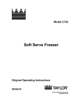
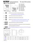
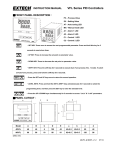
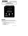
VT26 Series Shortform Manual In a hurry.. This controller, although quiet sophisticated, in it’s simplest form is very easy to install and use. In essence all you need to do is follow a few simple steps and away you go. The steps are: Product verification….To ensure that what you ordered and what you need are what you have. Wiring connection Guidelines….A simple help showing how to interpret the connection drawing on the side of the controller. Front Panel Description…..Explaining the displays and keys and their functions. Power up self test…..Explaining what information you see when the unit is powered up. Preliminary Quick Operational Test…..Some simple things to check once installation is complete. How to change the input Type….. Auto-Tuning your controller….Very important to get the best results from your system. Panel cut-out detail Before installing, please check the label to see that the controller you received is what you wanted and in fact meets your requirements. Points to check are Product verification check. The sections encircled by the colours on the label (as shown below) identify detailed information. MODEL NUMBER INTPUT: Available input types are 1. □ T/C Thermocouple:J. K. T. E. B. R. S. N.C 2. □ PT100 RTD:DIN PT-100; JIS PT-100 3. □ LINEAR Linear:4~20mA、0~50mV、1~5V、0~10V… For linear input check the scale low and high values. OUTPUT1 and OUTPUT2 (if installed) :Available output types are 1. □ RELAY Potential free contact 〔Normally open / SPST〕 1 2.□ SSR 24Vdc pulsed(pulsed voltage to drive SSR) 2. □ 4~20mA linear current 3. □ Other linear output signals such as mA, mV or volts. OPTIONS Avaliable optional extras include 1. □ RS-485:communications(MODBUS RTU format)When you have RS485 comms one controller can be configured to be the master and others as slaves. 2.□ Retransmission of the PV (process value) or SV (setpoint value) values that can be in the form of either mA or mV or volt signals. Each controller comes standard with two alarms Wiring Connection Guidelines. Power supply: The power supply voltage will be shown on the label and can be either 90~250 Volts or 18~36 Volts AC or DC VT4826 VT7226 DC24V AC90~264 50Hz / 60Hz 1 2 VT4926/VT9626 AC90~264 50Hz / 60Hz DC24V 13 15 VT9426 DC24V AC90~264 50Hz / 60Hz DC24V 19 20 AC90~264 50Hz / 60Hz 19 20 Sensor Input Signal: Standard input signals can be either Thermocouple or RTD which can be user configured via the key pad and menu. You may also have chosen one of the other optional inputs like linear (4~20mA or dcVoltage). This must be specified at the time of ordering and the controller will be supplied already set for that input. Wiring for the various inputs is shown below. 2 Thermocouple 8 9 7 8 B B 7 A 8 A 6 B 6 7 B 7 9 DC V / DC mA / DC mV VT7226 5 5 VT4926 VT9626 DC V DC mA DC mV 5 6 7 VT4926 VT9626 VT4926 VT9626 8 8 A 9 B 9 10 B 10 10 VT9426 VT9426 8 VT9426 Control output: 9 VT7226 VT7226 8 VT4826 VT4826 VT4826 7 DC V / DC mA / DC mV PT100 9 10 DC V DC mA DC mV 8 9 10 A B 8 B 9 9 10 DC V / DC mA / DC mV As standard our controller will be supplied with either a relay output, to be used to switch amongst other things a contactor for the load or a pulsed voltage output to drive a SSR (solid state relay) or if chosen at the time of ordering, other analog outputs such as the 4~20 mA output or the 0~10 volt output. The various terminal connection details are shown below. SSR / DC V / DC mA / DC mV Relay VT4826 11 12 OUTPUT 1 16 17 OUTPUT 2 VT4826 DC 11 12 OUTPUT 1 DC 16 17 OUTPUT 2 3 VT7226 11 VT7226 1 11 1 DC 12 DC 12 2 OUTPUT 1 OUTPUT 2 VT4926 / VT9626 17 15 18 16 OUTPUT 1 OUTPUT 2 2 OUTPUT 1 OUTPUT 2 VT4926 / VT9626 17 18 DC 15 DC OUTPUT 1 VT9426 16 OUTPUT 2 VT9426 17 18 15 16 17 18 OUTPUT 1 OUTPUT 2 OUTPUT 1 DC 15 16 DC OUTPUT 2 Front Panel Description FRONT PANEL DESCRIPTION ITEM DESCRIPTION 1. The process value. Displays the input measurement (temperature, pressure etc) PV 2. Displays the parameter name when selected. 3. Displays error messages when they occur. 1. The set value. Displays the setpoint. SV 2. Displays the parameter data when selected. 3. Displays the output percentage value when selected. 4 Auto tune LED indicator AT When the controller is auto tuning, the decimal point in the bottom right hand corner of the PV display will blink. Manual mode LED indicator MA When the manual mode is selected, the decimal point in the bottom right hand corner of the SV display will blink. Alarm 1 relay status LED indicator A1 This LED is lit in red when the alarm 1 relay is activated. This LED flashes when the alarm is configured as an Event/Soak timer and is in the process of counting down. Alarm 2 relay status LED indicator A2 This LED is lit in red when the alarm 2 relay is activated. This LED flashes when the alarm is configured as an Event/Soak timer and is in the process of counting down. Control output 1 status LED indicator C1 Illuminates in green when the control output 1 is activated. Control output 2 status LED indicator C2 Illuminates in green when the control output 2 is activated. KEYPAD DESCRIPTION SET KEY. 1. Press once to access the next programmable parameter. 2. Press this key for 5 seconds to reset alarm timer. UP KEY. Press to increase the setpoint or parameter value. DOWN KEY. Press to decrease the setpoint or parameter value. SHIFT KEY. Press the shift key for 5 seconds to execute Auto Tune process ( To abort the mode) Auto Tune process, press the shift key for 5 seconds. 5 Return to normal position. + Press once together Press the set and up keys once to return the normal operation after entering any parameter level or just wait for 5 seconds and it will return automatically. Access Parameter settings + Press together for 5 seconds Press the set and shift keys simultaneously for 5 seconds until the display reads Level in the top display. Then use the up and down keys to select programming level required. Press the set key to enter the level required. Access Engineering Units + Press together for 5 seconds Press the UP and DOWN keys simultaneously for 5 seconds to access “LnLo” and “LnHi” parameters. Power up self test Once you have connected the wires and are ready to turn the controller on the controller will do a self test. During the self test it will show you in sequence the following information. At the outset it will power up all the segments of the LED display to show that they are lighting correctly and none are faulty. Next it will show the measuring unit you have selected in the top display and the input type in the bottom. 6 Next it will show the high value of the range set in the top display and the low value of the range in the bottom. Ie 0~1000 °C. Thereafter it will revert to it’s normal display status showing the measured temperature in the top (PV) display and your setpoint in the bottom display. In the event that you wish to change one of these parameters please refer to the appropriate section in the full manual. Preliminary Quick Operational test. You now need to check that the overall system is now working correctly before attempting to set and tune the controller for final operating conditions. To do this change or ensure that the setpoint is higher than the measured temperature and then that the control output indicator “C1” is lit. At the same time check that the control device, either your contactor or SSR is switched on and that the PV reading is rising in temperature. When you drop the setpoint below the measured temperature the contactor or SSR should switch off. This will indicate that the controller is working correctly. If you are using your controller with an analog output, when the SV is higher than the PV the “C1” LED will flash rapidly. The SCR should be increasing the output and the PV rising in temperature. If in doing these tests you suspect something is not working as it should please refer to the full user manual. In order to change the setpoint you first need to press the key to select the digit you wish to change then use the up and down buttons to change it. How to change the input type. Press the + keys together for a few seconds until the display changes and reads “level” in the top display. Then use the up key to change from the in the SV display to You then press the key once to move to parameter. Now use the up and down keys to select the input type you need. You can now set the input range (This is not a setpoint high and low limiter but the input range) Press the reach the Lolt parameter Generally leave this a 0 °C. Press the key again a few times until you key again to reach the Hilt parameter. Set this to a 7 suitable high range setting to suit your application. Typically 0~100 or 0~400 or 0~600 etc etc. After you have completed press the + keys to revert to the normal operating display position. RANGE( ) RANGE( -50 ~ 1000 -58 ~ 1832 -50 ~ 1370 -58 ~ 2498 -270 ~ 400 ) -454 ~ 752 -50 ~ 750 -58 ~ 1382 0 ~ 1800 32 ~ 3272 0 ~ 1750 32 ~ 3182 0 ~ 1750 32 ~ 3182 -50 ~ 1300 -58 ~ 2372 -50 ~ 1800 -58 ~ 3272 -200 ~ 850 -328 ~ 1652 -200 ~ 650 -328 ~ 1202 -1999 ~ 9999 Auto-Tuning your VT26 Series controller. All installations are different and therefore you will need to set the control parameters of your controller to suite the dynamics of your system. This is called “tuning your controller”. In essence what will happen is that the controller will 8 automatically force the temperature to rise above the setpoint by a small amount, then drop back down again, repeat the procedure once again, then calculate the parameters itself and set them (PID Parameters). After doing this you should have the best possible control stability for your system. Steps to follow… Firstly choose a setpoint at which you wish to do the Auto-tune procedure and allow the controller and system to reach that temperature and stabilize. This will normally be at or around your final expected operating temperature. The auto-tune procedure should normally only be done once after installing the controller. (perhaps repeated again if the results are not quite good enough) It is best done during normal operating conditions of the machine or system, of course taking care that the expected overshoot does not damage you product. While the auto-tune procedure is in progress do not touch or change anything on the machine, just simply let it tune away. In general it should all be over in a few minutes but that depends on your system. You can choose to do the auto-tune procedure at that setpoint or at a setpoint 10% below the value as shown in the diagram by selecting “yes1” or “yes 2” as explained below. To begin the procedure press the set key three times to reach the parameter and then use the up and down buttons to choose either “yes 1” or “yes 2” as explained above. Once that is done the LED at the bottom left hand corner of the PV display will begin flashing and only stop on completion of the procedure. 9 Panel cutout detail. C A D Dd Va Jnb V c E B 型號 A B C D E a b c d VT-4826 48 48 6 100 45 45 +0.5 45 +0.5 60 48 VT-7226 72 72 9 80 67 68 +0.5 68 +0.5 90 72 VT-4926 48 96 9 80 91 45 +0.5 92 +0.5 120 48 VT-9426 96 48 9 80 45 92 +0.5 45 +0.5 48 120 VT-9626 96 96 10 80 91 92 +0.5 92 +0.5 120 96 10