1
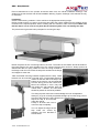
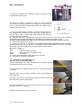
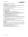
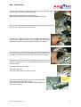
AXS - Step
Manual
ACDEOS BV
Touwbaan 1A
2352 CZ Leiderdorp
Netherlands
WWW.ACDEOS.COM
Date: Jan 2013
Rev. 5
AXS – Step Manual
Index
1
2
3
4
Technical specifications.................................................................................................3
Safety instructions ..........................................................................................................4
Constraints........................................................................................................................4
Controls .............................................................................................................................5
4.1
4.2
4.3
4.4
4.5
4.6
4.7
5
Operation...........................................................................................................................6
5.1
5.2
6
7
Deploy Operation procedure..........................................................................................................6
Stow operation procedure..............................................................................................................6
Manual Operation.............................................................................................................6
Mounting / Installation ....................................................................................................6
7.1
7.2
7.3
7.4
8
Step Control ....................................................................................................................................5
Signals.............................................................................................................................................5
Legal requirement according 2001-85 EC:...................................................................................5
Electrical Components ...................................................................................................................5
Power ..............................................................................................................................................5
Current control ................................................................................................................................5
Motor ...............................................................................................................................................5
Mechanical Installation...................................................................................................................6
Electrical Installation.......................................................................................................................8
Installation of the LED (optional): ..................................................................................................9
Testing the Step: ..........................................................................................................................11
Periodic maintenance / Inspection.............................................................................12
8.1
Cleaning ........................................................................................................................................12
8.2
Periodic maintenance / Inspection ..............................................................................................12
8.2.1
Small maintenance ...............................................................................................................12
8.2.2
Regular inspection ................................................................................................................12
8.2.3
Yearly maintenance / large maintenance............................................................................12
9
Repair ...............................................................................................................................13
9.1
Disassembly..................................................................................................................................13
9.2
Assembly.......................................................................................................................................14
9.2.1
Motor Assembly ....................................................................................................................14
9.2.2
Assembly of the Step Assembly ..........................................................................................14
9.2.3
Final Assembly......................................................................................................................17
10 Failure search..............................................................................................................19
11 Environment ................................................................................................................19
12 Certification .................................................................................................................20
13 Spare parts...................................................................................................................21
Appendix 1; ...........................................................................................................................25
Appendix 2; Installation drawings:...................................................................................28
AXS – STEP Manual rev5
2
AXS – Step Manual
1 Technical specifications
Product description Electric operated step for mounting outside under the floor of a vehicle.
Installation
Under the vehicle Floor at the front- middle or rear door
Dimensions
Step depth 300 mm - width depending on model 600, or 900 mm
For detailed dimensions please refer to the installation drawings
Weight
total 24-28 Kg depending at model.
Load
Maximum load 150 Kg (1500 N) this is always labeled on the Step.
Materials
Frame; steel plate work, EP corrosion protected.
Step: Aluminum profile with soft rubber front edge and Plastic corner pieces.
Life cycle
Tested life cycle of the step is 100.000 cycles with a load of 100 KG.
Electrical connection Waterproof 4 pin connector (IP65) on the step.
Drive
Electric motor 12V 20W (or optional 24V)
Electric signals
following electric signals are available: Step closed / stowed.
Safety functions
Motor switched off by current control.
Cycle time
Time required for opening or closing the step is approx 2,5 Sec
Legislation
The product fulfils 2001/85 EC Bus directive and 98/37 EC Machine directive.
AXS – STEP Manual rev5
3
AXS – Step Manual
2 Safety instructions
These Safety instructions should always be with the step. The operator must
be made aware of these instructions before operating the Step. Read these
safety instructions carefully and follow them.
The step is constructed to be an extra step to enter a vehicle. It should be used appropriately by
passengers as long as they are not heavier as the maximum load, to enter or exit a minibus, taxi
camper or other vehicle.
1.
Before you can operate the step you have to stop the Vehicle and make sure that the
hand or park brake is on.
2.
Before you operate the step, make sure that there is no person or obstacle at or close
to the step. Look out that there is no person or obstacle outside the vehicle in the motion
direction of the step.
3.
It is recommended that the step is only operated by the driver or other qualified
operators.
4.
The driver or operator must have a clear view at the step when he is operating the step.
5.
It is recommended to step on the middle of the step platform.
6.
NEVER drive away when the RED dashboard LED light is still on. The step is not
properly stowed.
7.
The step platform must be kept clean and free of oil and other slippery materials.
8.
When you have any doubt about the safety of passenger when using the step make
sure he is assisted.
9.
For any questions about the safe operation of the step, directly contact the responsible
persons.
10.
Never use the step for any other use than here described.
11.
Never overload the step.
12.
The step should always be operated until it is fully in or out.
13.
Repair and maintenance must be done by qualified and trained staff only.
14.
Only use original parts if you have to exchange parts from the step.
15.
If the anti slip profile at the step becomes slippery because of wear, the step platform
must be replaced.
16.
Always use the recommended cleaning materials.
17.
Report any unsafe condition of the step, or during it’s operation, to the step supplier.
3 Constraints
The Step On has been designed to be functional and reliable. The product is made as simple and
reliable as possible. It has been taken in consideration that the step will be mounted under a vehicle
in severe environmental conditions
AXS – STEP Manual rev5
4
AXS – Step Manual
4 Controls
4.1 Step Control
The step control is made as easy as possible. The controls comply with European 98/37 EC machine
directives. Functions and measurements are compliant with the EU Bus directive 2001/85 EC.
The electric step is an automatic system controlled by opening and closing of the vehicle door or
optionally by a driver operated switch.
4.2
Signals
The following output signals are available from the step electronics:
Step out.
This is a red LED to make clear to the driver that the step is not in the stowed position and that he
cannot drive away safely. This signal will blink when the step is moving in or out
Step in operation, moving in or out.
There is an audible signal when the step is moving in or out.
4.3 Legal requirement according 2001-85 EC:
Driver must have an indication that the step is fully stowed. It should be impossible to deploy the
step when a safety device fails. Manual operation is allowed.
The horizontal movement of a step shall be interrupted when it is loaded with a mass of 15 kg.
Extension of the step in the horizontal direction shall be protected by a safety device. In the event
of a safety devices coming into operation, the movement of the step shall immediately be stopped.
The Step On fulfils all these requirements.
4.4
Electrical Components
All electrical components directly outside the step cassette are water resistant to IP 65.
4.5
Power
12-volt commercial vehicle electrical system. Such a system consists of a 12-volt battery and an
alternator/generator system. The step performs all necessary functions when subjected to the normal
fluctuations encountered in a normally functioning 12V DC, commercial vehicle electrical system.
(optional 24 V system)
Note: The ECU is not protected against changing the polarity at the power lead. This will
damage the ECU.
IMPORTANT
The power line needs to be protected by a 20 Amp fuse. This fuse is not included in the cable
loom.
4.6 Current control
The Step has a current control function. The step will stop with a load of max 150 N in front of the
step. It will retract for a few centimeters and than try again to continue its movement out. It will try
three times to move out, then it will stay in the position where it was obstructed and fully returns when
the door is closed or the driver closes the step by a driver operated switch.
4.7
Motor
The motor specifications:
Voltage
Unloaded rotation speed
Unloaded current
Rated load
Rated current
Locked torque
Start / lock current
Current cut of by ECU
AXS – STEP Manual rev5
12V DC (or 24V optional)
70 rpm
2A
350 Ncm
5-6 A
850 Ncm
18 A
6,5 – 7.5 Amp
5
AXS – Step Manual
5 Operation
5.1 Deploy Operation procedure
The step must have clearance from the vehicle. The vehicle must have the parking brake on, and
then the step can be safely operated.
The electronics receive a signal from the door switch or driver switch. If a door switch is installed the
step will move out automatically once the door is opened.
Time for either the full deploy / out or the full stow / in cycle is approximately 2.5 seconds. When the
step is moving the red LED on the dashboard will flash until the step is completely out.
If the step encounters an obstacle it automatically stops. It will move backwards for a few centimeters
and then move forward again. If there is still an obstacle it will repeat this procedure three times, then
it will stop in the position where it encountered the obstacle.
5.2 Stow operation procedure
To stow the step the door should be closed or the driver has to give a signal that the step should
stow. The same rules apply as for moving out.
At closing a signal from the close switch will indicate that the Step is completely closed. This close
signal will also give the vehicle the OK that it is safe to drive the vehicle away, the Red LED light at
the dashboard will go off. If the step is not stowed properly the RED LED keeps blinking.
6 Manual Operation
In case the step fails, it is possible to operate the
step by hand. There are two mechanisms to
unlock the step for older versions of the step
(Straight long hole in bottom plate) use the
following procedure:
1.
Put a large screw-driver through the long
hole in the bottom cover in the slot in the motor
base plate.
2.
Move the end of the screwdriver in
outside direction. This will unlock the driving
mechanism. Now the step can be moved in or
out by hand.
3.
After moving the step in or out return the screw-driver in the slot to re-lock the step in the in or
out position.
For newer versions (from mid 2013) to be recognized on a long hole in the bottom plate under 45 deg,
use following procedure:
1.
Put a screw-driver through the long hole in the bottom cover in the slot of the plastic part.
2.
Turn ½ a turn anti clock wise. This will unlock the driving mechanism. Now the step can be
moved in or out by hand.
3.
After moving the step in or out return ½ a turn clock wise to lock the step.
7 Mounting / Installation
The installation can only be done by a company that is well known with bodybuilding or modifying
vehicles, which has the trained technical staff to do this job.
7.1
Mechanical Installation
For mounting the step you do not need to make any large vehicle adaptations. The step is placed
under the floor in the middle of the front, middle or rear door.
Chassis modifications are not needed.
Warning: Changing the vehicle chassis affects the strength of the vehicle. This kind of
changes is only allowed after approval of the vehicle builder / constructor. You need to consult
the vehicle builder for these kinds of changes. Acdeos cannot be made responsible or held
accountable for any vehicle / chassis changes.
AXS – STEP Manual rev5
6
AXS – Step Manual
Exact measurements of the product should be taken from the official installation drawings. Ask
Acdeos for the last revision and official installation drawing. Figures, drawings in this manual are only
for indication.
Installation:
Create a safe working condition. Lift the vehicle to the appropriate working height.
Define the place where you want to mount the step under the vehicle. Make sure the cassette can be
mounted on the required position without colliding with the chassis or other vehicle parts. Make sure
that the step is not to close to hot parts like the exhaust system. This can damage the step.
The picture below gives the basic principles for mounting the step.
Define the place for the 4 mounting bolts on the front. The holes for this fixation should be drilled in
the lower flange of the outer chassis bar of the vehicle. Drill the holes ø6.5 mm. Always protect all
drilled holes with zinc spray. Make sure there is enough material in
the flange under the hole. Place the step with two bolts at the flange
and support it at the rear.
Take the flexible mounting brackets supplied with the step. These
brackets can be mounted in several ways. The brackets should be
used to fix the rear side of the step to the
bottom of the vehicle. It is recommended
to find a strong point at the vehicle floor.
Mount the brackets in such a way that
they bridge the gap between step and
vehicle floor / chassis. The M8 studs
should be placed as vertical as possible
This fixing requires some technical knowledge and own interpretation.
Always try to go as vertically as possible straight up from the fixing point on
the rear of the step to the fixing points on the vehicles floor.
Adjust the step to be horizontal
under the vehicle.
Finally fit all bolts and nuts to
mount the step completely.
You can adjust the height of the
step under the vehicle by
adjusting the front brackets in
the slot holes.
AXS – STEP Manual rev5
7
AXS – Step Manual
7.2
Electrical Installation
For the correct installation and function of the step, follow these instructions:
1. Find a good routing for the cable to the front of the vehicle or the area where it will be connected
to the electrical system of the vehicle. The principal idea for the routing of the cable loom is as follows:
cable should run under the vehicle to the front of the vehicle. Then up through the engine
compartment and then inside the vehicle under the dashboard. In this area you normally find the
place for electrical connections. This change from vehicle to vehicle. The cable to the door switch
should run directly to the door-pillar where the door switch is mounted.
2. Look at the electrical diagrams in the rear of the manual appendix I.
3. There are in principal two different possibilities for the operation of the step.
1 - By door switch. Steps moves out automatically when the door opens
2 - By driver operated switch on the dashboard where the driver operates the step. In this case, it is
still recommended to install the door switch. Without the door switch the driver could forget to close
the step when the door is closed, and drive away with an open step.
4. Find a good location for the door switch.
See example for the front door of a VW Crafter / MB Sprinter.
5. Connect the green wire to the handbrake switch or other signal
indicating that the vehicle is stationary. You need a signal when the
vehicle is stationary. The handbrake switch is not supplied with the
step.
For safety reasons we recommend to use this signal. If you decide
not to use this signal Acdeos cannot take any responsibility on
the safe operation of the step.
6. If you choose for automatic door operation, place the door switch in the door pillar. If the door is
closed the switch must be operated. The door switch is as standard supplied with the cable loom.
7. We recommend using the original door switch installed by the vehicle manufacturer. This
switch is placed at the ideal place and tested. Just connect the ground signal of the step at the
ground signal of the door switch.
If you want to use the extra safety of the handbrake or an additional
switch at the dashboard you would in this case need to use an extra
relays. You don’t need the extra relays if the step is supplied with a
single wire door switch that connects direct to ground (Electric
schedule S150 001 rev4 serial numbers > 2000).
8. If you use the mechanical switch supplied with the step: Make
sure the Switch is operated in a strait line by the door. If the switch is
pushed under an angel it will block and fail!
9. Steps with serial numbers > 3280 have a magnetic door switch.
This should be mounted following these instructions:
10. Mechanical Installation Find the right place at the door to install
the door switch, preferable around the area in the doorpost where you
find the original door switch. Make sure there is around 35 mm open
space inside the doorpost. Drill a hole of 15 mm .
11. Place the door switch and fix with a screw
AXS – STEP Manual rev5
8
AXS – Step Manual
12. Place the magnet at the opposite position at the door. Fix the
magnet with a bit of PU glue
13. Adjust the switch if needed to create the correct distance
between the front of the switch and the magnet of 2-4 mm when the
door is closed The Switch makes contact when the magnet is at a
distance of around 5-7 mm.
14. If you choose for driver operation, you should place a switch on
the dashboard and connect it to the Green wire. Closed signal =>
step out. Open signal => step stowed. Also install the door switch to
prevent mistakes by the driver.
15. Place the red LED in the dashboard in the direct view of the driver. Connect the wire to ground.
The LED turns on red when the step is out and blinks when the step is moving in or out.
At Serial numbers higher than 4000 The Led must be connected to power instead of ground.
16. Connect the black wire to ground.
17. Connect the red wire to 12V power. You need to add a fuse of 20 Amp between the battery
and the power cable. It is your decision to connect the step at constant power or at power behind the
main switch. We recommend placing the step behind the main switch.
18. Cable colours:
black
Ground
Red
Power (Use a 20 Amp fuse)
Green
Ground signal for operating the step
Yellow
LED signal
19. Connect the cable loom to the step with the connector.
20. The step is now ready for operation.
7.3 Installation of the LED (optional):
Versions up to serial number 4000.
There is a possibility to fit a front LED light strip in the Step. The Step
is already prewired to fit the LED light.
The step should be completely fitted under the vehicle and electrical
connected.
Bring the step in the out position (deploy). Lift the yellow rubber and
pull out the strip.
Pick up the two wires on the right hand side of the step. Connect the
wires with the two pins at the led light.
The LED should light up. If not change the two wires for the right
polarity. (The led is +/- sensitive.)
Slide the two connectors firm at the two pins.
AXS – STEP Manual rev5
9
AXS – Step Manual
This is a relative open electrical connection that needs to be protected
against water. So use plenty of white Vaseline (or silicone sealant)
around the connectors.
Push the led strip in the aluminum profile with the two pins under the
black plastic corner.
Than push the strip in the profile over the full length.
Stop About 15 cm before the other end and first place the end of LED
strip under the plastic corner and than push in the last bit.
During the whole fitting the LED should light so you can see if it is
properly connected.
Close the step. During opening and closing the LED should blink.
When the step is closed the LED is off.
Versions above serial number 4000.
Remove
Remove the right corner from the step, by removing the two screws
in the front and rear. Front screw is behind the black front rubber.
Slide the rubber aside to get access at the front screw.
Remove the black rubber seal on top of the step
You don’t need to remove the bottom cover
Screw
Remove
Modify the step corner by removing the plastic part that fits in the slot
of the aluminum profile. This is soft plastic and can be removed by a
normal knife.
First cut the standing part off
Secondly cut out a opening for the Led wires, by cutting away a
square piece in the bottom of the insert.
Below picture is showing the end result.
Connect the Led at the cable loom from the step.
The step is pre-wired for the LED
You don’t need to remove the bottom cover
Insert the Led in the aluminum profile. Make sure the Led is over the
full length pushed down at the bottom of the profile, other wise you
can not fit the top rubber. Use plenty of liquid soap to make the led
slide in the profile.
AXS – STEP Manual rev5
10
AXS – Step Manual
Align the end of the LED with the aluminum profile on both sides of
the step. Fold the wires down as on the picture Check the LED lights
after installing the Led strip.
Place the transparent rubber profile as supplied with the LED kit. Use
plenty of liquid soap to make the mounting go easy.
First slide in the rear lip than push in the front lip with a medium size
screwdriver. Don’t damage the LED or the rubber. This job requires
some practise.
Mount the end corner. Make sure the cable from the Led stays free
from the sharp edges.
The end result must look like this picture
7.4 Testing the Step:
You should test the step after installation. Follow these instructions:
1.
MOUNTING – Check if the all mounting bolts are in place and tightened.
2.
MOUNTING – Bring the step out and step on it with two persons Max 150 Kg. Check if the
mounting of the step is strong enough for this weight. The construction of the step is such that a
weight of 150 Kg will give a deflection of the step. This is normal !!
3.
ELECTRICAL INSTALLATION – Move the step out and in by electrical operation.
Check if the step is moving for strange noises and unequal movements.
Check if the step stops automatic at the end of the stroke.
Check if the red LED on the dashboard turns red when the step is out.
Check if the buzzer works while the step is moving in or out. (If not disconnected)
4.
SAFETY FUNCTION – Move the step out and try to stop it with your hand. The step should
stop move back and come out again. It will try this for 3 times. Then it stops. It should go back in after
closing the door.
5.
INTERLOCK VEHICLE –Take the vehicle off the handbrake. Try to operate the step. It
should not be possible to operate the step.
If this small test procedure is followed with success the step is ready to be used. If one of the tests
fails the problem should be resolved before putting the step in to use.
AXS – STEP Manual rev5
11
AXS – Step Manual
8 Periodic maintenance / Inspection
8.1
Cleaning
The step must be cleaned in the normal cleaning schedule of the vehicle, depending on the use of the
vehicle and the filthiness of the operation. Normal non-aggressive cleaning materials, as used for
cleaning the other parts of the vehicle, should be used.
The use of high-pressure water cleaners is not recommended.
Do not use aggressive solvents; these could affect the paint, rubber and glue as used on the step.
8.2
8.2.1
Periodic maintenance / Inspection
Small maintenance
The product has low maintenance need. This means that it is not necessary to grease any of the
moving parts on a regular basis.
8.2.2
Regular inspection
Following the vehicle inspection schedule, check following points:
1.
MOUNTING – Check if the all mounting bolts are in place and tightened.
2.
MOUNTING – Bring the step out and step on it with two persons Max 150 Kg. Check if the
mounting of the step is strong enough for this weight. The construction of the step is such that a
weight of 150 Kg will give a deflection of the step. This is normal !!
3.
ELECTRICAL INSTALLATION – Move the step out and in by electrical operation.
Check if the step is moving for strange noises and unequal movements.
Check if the step stops automatic at the end of the stroke.
Check if the red LED on the dashboard turns red when the step is out.
Check if the buzzer works while the step is moving in or out. (If not disconnected)
4.
SAFETY FUNCTION – Move the step out and try to stop it with your hand. The step should
stop move back and come out again. It will try this for 3 times. Then it stops. It should go back in after
closing the door.
5.
INTERLOCK VEHICLE –Take the vehicle off the handbrake. Try to operate the step. It
should not be possible to operate the step. (unless the handbrake interlock is not installed)
8.2.3
Yearly maintenance / large maintenance
Large maintenance should be done once every year or at least every 30.000 cycles.
If the number of cycles per year is less than 10.000 the large maintenance interval can be extended to
1.5 years.
Large maintenance:
Bring the step in the out position. Remove left or right plastic corner. Loosen the front and rear screw
of the plastic corner. Front screw is behind the rubber front. Slide front rubber aside to make front
screw accessible.
Remove bottom plate by removing the two screws and sliding the bottom plate out of the aluminum
profile. Check all moving parts like, arm gears, push rods and wheels for excessive play. If there is
excessive play on moving parts it is recommended to replace these parts.
Check the adjustment of the in and out switch.
Check wires and electrical connections for possible failures.
Clean the inside of the step and grease moving parts with normal bearing grease.
Close the step. First place bottom plate than replace plastic corner.
AXS – STEP Manual rev5
12
AXS – Step Manual
9 Repair
The repair of the step is simple and can be done with the normal available workshop equipment.
The most repairs can be done under the vehicle, but this manual describes a full assembly of a step
removed from the vehicle.
9.1
Disassembly
Bring the step in the out position either electric or by manual operation.
Move the front rubber aside and turn the screw holding the step corner 1
turn back
Turn the screw holding the back of the step corner 1 turn back
Remove the step corner
Remove two screw from the bottom cover and remove the bottom cover.
Remove the spring holding the motor assembly
Remove ECU
Remove two M8 nuts holding the motor assembly
Remove springs from both pushrods and disconnect the push rods
from the gear arms.
Slide the step out of the chassis
Remove all needed parts.
AXS – STEP Manual rev5
13
AXS – Step Manual
9.2
9.2.1
Assembly
Motor Assembly
Grease the 14 pin connector with white Vaseline before connecting it to
the ECU.
Place two clamps over the micro switches so that they are closed.
Connect the motor + wiring and ECU at a power source.
Let the motor run forward and back ward by pressing the door switch.
Spray a little silicon spray at the rubber sealing from the motor
Check the Amps from the motor. They have to be at nominal 2,4 Amp max 2,5 Amp.
Fit the motor with the two counter sunk screws.
Put a firm bit of grease at the gear.
Place the nylon washer at the gear and place the reinforcement plate.
Let the motor run again and check the Amps. Nominal 2,5 Amp - max 2,8
Amp
Fit the two Micro switches at the motor base plate.
Motor assembly is now ready for final assembly.
9.2.2
Assembly of the Step Assembly
Place the two oval rubber grummets in the opening of the rear step
profile. Use liquid soap to make the job go easy.
Slide the two rollers in the rear profile. Spray a little silicon oil at the
rollers
Slide the two yellow rubber profiles in the front step profile. Use lots of
liquid soap to make the profile slide easy.
Take the sliding assembly. Spray a little Silicon oil at al the turning points for the wheels. Place the
wheels at the sliding assembly. Check if the wheels run free and easy.
Take the front and rear step profile and connect them together.
Slide all required M8 bolts in the slots in the profiles.
Place the sliding assemblies through the hole in the rear step
profile and over the 6x M8 bolts. Place the nuts at the bolts but
do not tight up.
Take the two arm gears; take a paint brush with a firm bit of
grease. Grease the gears from the gear arms.
Spray silicon oil at the nylon rings and place them at the gear
arms. Slide the distance bushing in the nylon rings.
AXS – STEP Manual rev5
14
AXS – Step Manual
Place the gear arms at the step assembly over the two M8 bolts. Align
the gear arms with the two marks at the gear.
Place the motor assembly over the gear arms.
Make sure the lip slides in the slot from the Aluminium profile.
Place the tow large washer’s and tight up the first nut than check if the arm
gear can turn freely without to much friction.
If the arm is too tight, remove the nut and washer and place a 0, 2
mm shim at the distance bushing. Tight up again and check again.
Repeat this until the arm has the proper freedom of movement.
Than tight up the second nut and check if the motor base plate can
move free in the slot. If the motor base plate can’t be moved free
by hand in the slot than you need to ad a shim or more if needed.
After that both turning points have been adjusted connect to power
again and let the motor run in both directions. Motor current must
be below 3 Amp.
Fix the ECU with the two screws
Take the 2 push rods
Put some grease at the ball at the arm gear.
Place the push rots trough the holes of the rear step profile
and connect to the ball at the arm gear.
Secure the ball joint with the spring pin. Make sure the pin
is connected properly.
AXS – STEP Manual rev5
Wrong placed
spring pin
15
AXS – Step Manual
Turn the 4 screws for the two corner pieces
in the holes and fix the complete than turn
them back for 3 turns.
Place the cable for the LED light under the rubber profile
Strap electric cable loom
Connect the 8 straps at the points for
fixation.
Now the step assembly is ready for
final assembly
AXS – STEP Manual rev5
16
AXS – Step Manual
9.2.3
Final Assembly
Take the welding assembly
Slide a sliding assembly with 4 wheels through the tube and check if it runs free.
Take a long small paint brush and grease only the both sides of the tube inside
at the front and the rear.
Slide the rubber grummets around the two 30 x50 tubes
Place the welding assembly upside down at a table and fixate it.
Take the step assembly and slide it in the chassis.
Make sure the push rods are completely retracted.
Slide the assembly a few time’s in and out, feel if it
runs free
Than slide in.
Check if the rear and front profile are aligned at the
side.
Check if the tubes from the chassis in the holes in
the rear profile are in the centre. The Aluminium
must be free at least 1 mm from the steel tube
Check if the sliding chassis is in the centre of the tube at the front side.
With the assembly in closed position fix the 2x 6 nuts of the sliding
assembly
Move the assembly in and out by hand and feel if it runs free.
Loosen the two nuts from the motor assembly. Adjust the
motor assembly to the centre of the step. Measure from
the left and right sliding bar from the sliding assembly.
Pull out the assembly in the out position
Connect the ball joints from the push rods at the chassis.
Connect the cable chain at the chassis
Move the step in and out and feel if it still runs free.
AXS – STEP Manual rev5
17
AXS – Step Manual
If it moves difficult check if the push rod are equal in length. If the step is not running parallel with the
chassis it could be that the gear arms are one tooth offline. Check left and right ball joint position
compared to a vertical line in the Aluminium step profile when the step is 50% out.
Switch adjustment:
Slide the step in closed position. Move the right micro switch in such a position that the switch just
makes contact. You can hear the switch when the contact is closed. Fix the switch with the two
screws. Use proper tools so that you can fix the two small screws with
the appropriate torque.
Slide the step out until max out position. Than slide it 5 mm back in.
Now adjust the out switch in the same way as the stow / in switch has
been adjusted.
Take the spring assembly and pray silicon oil at the spring assembly.
Lock the motor assembly with the spring.
Turn the step from upside down position to the normal position.
Connect the cable loom to the power source
Let the step move in and out by the motor.
Checks if the Micro switches for in and out have been adjusted properly.
In closed position the step should stay on the metal end lock of the sliding
assembly and the tube’s of the chassis.
Let the step run in and out and check the motor current.
Ideally the step should move in and out with a motor current below 4 amps.
Maximum allowed motor current in this situation is 4,5- 5 Amp.
If motor current is above max Amp check if any parts are colliding during
the movement of the step. Find the source of resistance and repair it.
NEVER ADJUST THE CURRENT CONTROL OF THE ECU TO MAKE THE STEP WORK!
Turn back to upside down position.
Place the left corner piece fix with the screws. Make sure the cable for the LED is free.
Now you are at the point of closing the step,
Check once more if al nuts and bolts have been tighten up to the right
torque.
Also check the screws from the micro switches.
Check if al cables have been tight up properly and are free from
moving parts. Check if the two cables for the LED are not tight
between the motor housing and the aluminium step profile. This is a
course of high motor Amps.
Slide the step bottom cover in place and fix with the two screws.
You can use a magnet to lift the end of the bottom cover, to make it
slide in the corner piece easier, or pre bend the cover plate by hand
Place the left corner piece - Fix the rear screw.
Slide the front rubber away as much as possible and fix the front screw.
Slide the front rubber back until it is under the front end of the corner
piece.
Check if the corner pieces are really fixed by pulling the side ways
Step is ready for operation again.
AXS – STEP Manual rev5
18
AXS – Step Manual
10 Failure search
Failure
Step makes a rattling noise
before is close completely.
Step sometime doesn’t move out
Problem
Close switch not properly
adjusted.
Step does not come out when
door is open
Hand brake not applied
Step does not come out when the
vehicle engine is running but
does move out when the engine
is stopped
At the end of the out movement;
step starts moving in and out.
ECU problem.
Solution
Adjust the close switch in the
direction
of
the
ECU.
Close switch is the switch near
the spring
Put the vehicle at the handbrake.
This can only be the case when
the step is installed with a
handbrake interlock.
Replace ECU
Open switch not properly
adjusted.
Adjust out switch in direction of
front side of the step.
Step does not move out.
Fuse burned.
Replace fuse.
Step does not move out.
Step damaged by stroke
from a curb stone or speed
bump
Check for deformation in the
mechanical system and repair /
replace these.
Step does not move in when door
is closed
Door switch broken:
Replace door switch.
Step does not move in when door
is closed
Door switch not properly
adjusted.
Check if door is pushing the
switch up to the contact point.
Step stops during movement and
goes back and forward than
stops.
Step is encountering
obstacle.
Remove obstacle.
This can be dirt or ice inside the
step.
Step does not move
Bad electrical contact.
an
Check cable loom and connectors
11 Environment
The use of energy from the step is reduced to an absolute minimum.
The AXS - Step is made of durable materials which all can be recycled. All different materials can
easily be separated from each other for separate recycling.
AXS – STEP Manual rev5
19
AXS – Step Manual
12 Certification
Certification
Product
Type
AXS 900 A
Company
Address
City
Country
Website
Legal represented by
Product description
AXS
Electrical Sliding step
AXS 600 A
STEP
Production under responsibility of
Acdeos BV
Touwbaan 1A
2352 CZ Leiderdorp
Netherlands
WWW.ACDEOS.COM
Mr. A de Moes
Conformity
Product is designed, tested and produced confirm:
The loading recommendations in the Machine directive
98/37/EG
Step is tested for a maximum weight of 150 Kg
On behalf of producer:
Name / Function
A de Moes / Engineering
Date
15 September 2009
Place
Leiderdorp, Netherlands
AXS – STEP Manual rev5
20
AXS – Step Manual
13 Spare parts
Chassis
item
1
2
3
4
Part
Mounting bracket Left
Mounting bracket Right
Rubber seal
Rubber cap
Part number
S150 013
S150 012
S150 048
S150 035
item
1
Part
Mounting parts
Part number
S150 01 001
AXS – STEP Manual rev5
21
AXS – Step Manual
Step assembly
item
1
2
2
3
3
4
4
Part
Step corner
Bottom cover 600 mm
Bottom cover 900 mm
Front rubber
600 mm
Front rubber
900 mm
Rubber front seal 600 mm
Rubber front seal 900 mm
Part number
S150 004
S153 02 06
S154 02 06
S153 02 05
S154 02 05
S153 02 04
S154 02 04
Sliding assembly
item
1
Part
Wheel
AXS – STEP Manual rev5
Part number
S150 027
22
AXS – Step Manual
Motor assembly
item
1
2
3
Part
ECU
Motor
Micro switch
AXS – STEP Manual rev5
Part number
S150 009
S150 101
S150 020
23
AXS – Step Manual
item
1
2
3
Part
Washer
Gear arm
Ring
Part number
S150 039
S150 032
S150 042
item
1
Part
Push rod assembly
Part number
S150 01 003
AXS – STEP Manual rev5
24
Appendix 1;
Electric schedule serial numbers AI400 – 2000
AXS – Step Manual
Electric schedule rev 4 serial numbers AL 2000 => 4000
AXS – STEP Manual rev5
26
AXS – Step Manual
Electric schedule rev 5 serial numbers 4000 => …
AXS – STEP Manual rev5
27
AXS – Step Manual
Appendix 2; Installation drawings:
AXS 600A
AXS – STEP Manual rev5
28
AXS – Step Manual
AXS 900 A
AXS – STEP Manual rev5
29