1
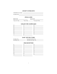
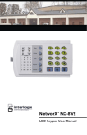
HILLS® Series LED Code Pad
User Manual
Not all features may be available on your system
Check with your installer to find out which features are programmed
Page 2
TABLE OF CONTENTS
•
Code Pad Diagrams .......................................................................................2
•
Glossary of Terms ..........................................................................................4
•
Understanding the Code Pad Lights...............................................................5
•
Code Pad Control Tones ................................................................................6
•
Fully arming the system – On Mode ...............................................................7
•
Fully arming the system – Quick Arm Mode ...................................................7
•
Partially arming the system – Partial Mode ....................................................8
•
Disarming – from the On or Partial Mode .......................................................8
•
Bypassing – Individual Zones .........................................................................9
•
Group Bypass .................................................................................................10
•
Changing & Adding User Codes.....................................................................11
•
Deleting User Code ........................................................................................12
•
Walk Test........................................................................................................12
•
User Code Authorisation.................................................................................13
•
Setting the Door Chime ..................................................................................13
•
Exit Mode – Extend Exit Timer .......................................................................14
•
Code Pad Emergency Keys............................................................................14
•
Viewing Alarm Memory...................................................................................14
•
Reset Latched Alarms ....................................................................................15
•
Setting System Date .......................................................................................15
•
Setting System Time.......................................................................................16
•
Set Code Pad Tones ......................................................................................16
•
Program Telephone Number ..........................................................................17
•
Viewing Telephone Numbers..........................................................................18
•
Deleting Telephone Numbers .........................................................................19
•
Communicator, Battery & Siren Test ..............................................................19
•
Service Light ...................................................................................................20
•
Emergency Evacuation Plans.........................................................................21
•
Warranty Statement........................................................................................22
•
Zone List .........................................................................................................Back Page
Page 3
GLOSSARY OF TERMS
Authority Level: The level of access an individual has when using an alarm panel.
Central Station: Location where alarm data is sent during an alarm report.
Chime Feature: An option that allows the code pad to sound a ding-dong whenever an
entry/exit door is opened.
Codes: Can be either User Codes (relating to a person) or Function Codes (a toggle switch to
turn specific functions on/off). NOTE: A system may have either 99 four (4) digit codes or 66
six (6) digit codes, but not a mixture of the two.
Dialer Delay: An option that allows a delay in reporting to the central station.
Duress Code: An option that allows a special code to be sent to the central station that
indicates the alarm system is being operated under duress.
Forced Arming:
An option that allows the system to be turned on (ARMED) with one or more zones open. A
system that is ready to be “force armed” will flash the ready light. (Note: Those zones that are
not ready will not create an alarm.)
Function Code: A Function Code is either a four (4) or six (6) digit code that has been
programmed by the installer to operate a device.
Group Bypass:
operation.
An option that allows the user to bypass multiple zones with a single
Master Code: A master PIN code that can arm & disarm the alarm system, and can add and
delete user PIN codes.
Partial Arm: A mode used to arm the perimeter and unused areas of an occupied premises.
Perimeter: The outer edge of the protected area, typically the windows and doors fitted with
alarm sensors.
Quick Arm: An option that allows you to turn on (ARM) the security system by pressing either
the [ON] or [PARTIAL] key on the code pad control (for ARMING only) as programmed by the
installing company.
Universal Arming (Uni Arm): When enabled, your alarm system can automatically determine
whether to arm in the Full mode or in the pre-set Partial mode by looking to see if you exit your
premises or stay inside after arming your system. NOTE: This feature can be used in
conjunction with “Quick Arm”.
User Code: A four (4) or six (6) digit entry used to arm or disarm the system.
Page 4
UNDERSTANDING THE LIGHTS
Armed Light
The armed light is “on” when the system is armed. The armed light is “off” when it is disarmed.
The armed light will flash when there has been an alarm during the previous arm cycle.
Bypass Light
The bypass light is “on” when any zone in this code pad’s area is bypassed. The zone(s) that is
bypassed will also be illuminated. If the bypass light is “off”, no zones are bypassed.
Chime Light
The chime light is “on” when the chime feature is “on”; “off” otherwise.
Exit Light
The exit light is “on” during the exit delay. Please note that the light will flash during the last 10
seconds of the exit delay as a warning that the time is running out. (The user may want to
restart the exit delay if the exit light is flashing in order to prevent an alarm. The user may then
press the [Exit] key to restart the exit delay before the delay expires.)
Fire Light
A steady fire light means a fire zone has been faulted. A rapidly flashing fire light means that a
fire zone is in a trouble condition.
On Light
The on light is “on” when the system is armed. The on light is “off” when it is disarmed.
Partial Light
The partial light is “lit” when the system is armed in the Partial Mode. All non bypassed zones
will be delayed and follow the Partial delay time. When armed in Partial Mode, the Arm, On,
and Bypass lights will also be “lit”.
Power Light
The power light is lit if the primary power is on. The power light will flash if the system detects a
low battery condition.
Ready Light
The ready light is “lit” when the system is ready to arm and “flashes” if ready to force arm. The
ready light is off when the system is not ready to arm because of a zone(s) being faulted.
Zone Light
The zone lights are “off” when everything is normal. A zone light will be “lit” if the zone has
been bypassed. If a zone light is “flashing”, that zone is in alarm or has been faulted. If a zone
light is “flashing” rapidly, it means that the zone is in a trouble condition. Trouble conditions
are: Hardwire Zone Tamper; Wireless Zone Tamper, Sensor Low Battery and Sensor
Loss of Supervision
(A combination of Alarm/Fault and Tamper/Trouble will produce a rapid “flashing” light for a
short period of time, followed by a slow “flashing” light.)
Page 5
CODE PAD CONTROL TONES
•
Beeps for all key presses Sounds a continuous tone during the entry delay time.
•
Pulses when a day zone is violated while the system is disarmed.
•
Pulses when a fire zone has a trouble condition.
•
Beeps 3 times for trying to arm with the “Ready” light off, if “Force Arming” has not been
selected.
•
Beeps for 1 second or emits a “ding-dong” sound for the “Chime” feature.
•
Beeps during an exit delay; beeps rapidly for the last 10 seconds of an exit delay; and
beeps 1 second at the end of the exit delay.
•
Pulses when the armed status changes and the AC power is off.
•
Pulses when the armed status changes and any zone(s) is bypassed.
•
Pulses when the armed status changes and a low battery is detected.
•
Pulses when the armed status changes and a tamper condition is detected. Beeps to
indicate telephone line cut, if selected.
•
Pulses when one or more of the following conditions are detected: zone or box tamper,
low battery, AC power fail, or expander trouble.
Entering a valid code will silence the code pad sounder when it is pulsing. Please
contact your installer if a trouble condition exists.
Page 6
FULLY ARMING THE SYSTEM – ON
MODE
ON is used when the user is away from the premise and wants the interior protected. To arm
in the ON Mode:
1.
2.
Close all protected doors and windows. Ready light will light when all protected zones and
sensors are secure. NOTE: If any zones are bypassed, a sensor in that zone can be violated
without affecting the ready light. The security system will not arm if the ready light is not on. If
the power light is off, you have no AC power. Restore power if possible. If not, contact your
installation company.
Enter your 4 digit user code to arm the system. The armed and exit lights will illuminate. You
may now leave the building via the designated exit path.
Note: The exit light will flash rapidly for the last 10 seconds of the exit delay as a warning to
the user that the exit time is about to expire.
Key Sequence
Operation
Example shows a User code of 1234
being used to set the system to the
ON Mode.
FULLY ARMING THE SYSTEM – QUICK
ARM MODE
Quick Arm is used when the person arming the alarm system does not have a user code, is
leaving the premises and wants the interior protected. To arm in the Quick Arm Mode:
1.
2.
Close all protected doors and windows. Ready light will light when all protected zones and
sensors are secure. NOTE: If any zones are bypassed, a sensor in that zone can be violated
without affecting the ready light. The security system will not arm if the ready light is not on. If
the power light is off, you have no AC power. Restore power if possible. If not, contact your
installation company.
The [ON] key to arm the system. The armed and exit lights will illuminate. You may now
leave the building via the designated exit path.
Note: The exit light will flash rapidly for the last 10 seconds of the exit delay as a warning to
the user that the exit time is about to expire.
Key Sequence
Operation
Example shows ON key being used
to set the system to the Quick Arm
Mode.
Page 7
PARTIALLY ARMING THE SYSTEM
– PARTIAL OR HOME MODE
Home mode allows you to temporarily exclude some rooms from security arming. For
example, you may wish to exclude bedrooms at night when they are in use. Home mode is
also used for protecting exterior doors and windows (the home perimeter) when the user is
inside.
Partial is used when the user is inside the premise and wants protection around the
perimeter. Listed below are the steps to arm in the Partial mode:
1.
2.
Close all protected doors and windows. Ready light will light when all protected zones and
sensors are secure. NOTE: If any zones are bypassed, a sensor in that zone can be violated
without affecting the ready light. The security system will not arm if the ready light is not on. If
the power light is off, you have no AC power. Restore power if possible. If not, contact your
installation company.
Press the [PARTIAL] key. The bypass light will illuminate if any zone(s) is bypassed. The
light(s) corresponding to the bypassed zone(s) will illuminate, alerting the user that a zone(s)
may be unprotected and can be faulted without an alarm.
Key Sequence
PARTIAL
Operation
Press the Partial key to partially arm
your premises
DISARMING – FROM THE ON OR STAY MODE
When you enter the protected area through one of the designated Entry/Exit doors, the code
pad control will sound a solid continuous tone for the duration of the entry delay time, or until
you enter a valid code. After entering a valid code the red armed light will go off and the tone
will stop. The security system is now DISARMED. If a valid code is not entered before the
end of the entry delay, an alarm will occur. (NOTE: If the red armed light is flashing during
the entry delay, the alarm system has been activated in your absence. Leave the building
immediately and call your alarm company and/or the police from a safe location.)
Key Sequence
Operation
Enter your user code to disarm the
system from the On or Partial mode.
Page 8
BYPASSING – INDIVIDUAL ZONES
Bypassing is used to temporarily exclude one or more zones that would normally be
protected. For instance, a pet may need to be left in a part of the house that is usually
protected. If you wish to bypass one or more zones, this must be done while the system is in
the disarmed state. The following steps are used for bypassing zones. Once you have
Bypassed the zone(s) you may Arm the system via the ON or PARTIAL Mode. When your
security system is disarmed, any zones that has been temporarily isolated or bypassed will
be reset, and will therefore be protected when the system is armed again. To manually unbypass zones, perform the bypassing procedure on a zone that is already bypassed.
The corresponding light for that zone will go off when un-bypassed.
Key Sequence
Operation
This example shows a
bypassing zones 4 and 5.
1. Press the [BYPASS] key.
BYPASS
user
2. (Optional) Enter a user code. (The
bypass light flashes.)
0
4
0
5
BYPASS
3. Enter a 2-digit zone indicating the
zone you wish to bypass.
(Example: Press the [0] and the [4]
key for zone 4, press [0] and the [5]
for zone 5.) The corresponding light
for that zone will turn on when
bypassed.
4. Press the [BYPASS] key again.
NB: Pleased check with your security
installation company to determine if a
user code is required.
Page 9
GROUP BYPASS
By pressing the [BYPASS] key, followed by the [0][0] key, then the [BYPASS] key again, all
zones that are designated as group bypass zones will be bypassed. Now you can arm your
system in either the [ON] or [PARTIAL] mode. Once armed pressing the [BYPASS] key
again will toggle the bypassed zones on and off.
Key Sequence
Operation
1. Press the [BYPASS] key.
2. Enter a user code. (The bypass
light flashes.)
3. Press the [0]-[0] keys. The group
bypass zone lights will turn on when
bypassed.
4. Press the [BYPASS] key again.
NB: Please check with your security
installation company to determine if a
user code is required.
Page 10
CHANGING & ADDING USER CODES
On occasion you may need to change your arm & disarm codes, either as a security
measure or for your own convenience.
User Codes are 4 digits long and must all be different to each other. A master Code must be
used to Change and Add user codes. The default master code is user code one [01] with a
code of [1234]. Any user code can be assigned as a master code (See User Code
Authorisation). Note the system must be disarmed before user codes can be changed or
added.
Key Sequence
Operation
1. Press [*] and [5].
2. Enter an existing master code.
3. Enter the user code to add or
change.
4. Enter the new four-digit user
code.
5. Repeat steps 3
additional user codes.
and
5. Press [#] when completed.
Page 11
4
for
DELETING A USER CODE
You may be required to delete a user code, for example, when a member of the household
leaves home, or the home is purchased from another family.
Key Sequence
Operation
1. Press [*] and [5].
*
5
1
2
*
5
CHIME
CHIME
2. Enter an existing master code.
3
CHIME
CHIME
4
3. Enter the user code to be deleted
(e.g. user code three 3)
4. Press the [Chime] key four (4)
times to delete the user code.
5. Repeat steps 3
additional user codes.
#
and
4
for
6. Press [#] when completed.
WALK TEST
Walk test is used to test the functionality and should be performed regularly. When in walk
test mode the code pad transmits the chime sound each time a zone is activated, and will
light the activated zone number in the code pad for the duration of the walk test period. You
must exit the walk test mode when you have completed testing or are satisfied the zones
function correctly.
Note: the alarm system will not report to the control room during the walk test.
Key Sequence
Operation
1. Enter [*] [CHIME].
2. Enter a master code. The system
is now in walk test mode.
3. Walk past each motion sensor and
return to the code pad to check each
zone light to validate the sensors are
working correctly.
4. Enter a master code to exit walk
test. If no master code is enter walk
test mode will automatically exit in 15
minuets.
Page 12
USER CODE AUTHORISATION
Any user code can be assigned the master code status to allow that user to change or add
other codes and provide access to other system functions.
Key Sequence
Operation
Example shows enabling user two
[02] as a master code.
1. Press [*] [6].
2. Enter an existing master code.
3. Enter the user code to have
changed to a master code.
4. Press [4] key. LED 4 will light up
to indicate the user is now a master
code. If LED 4 is not lit then it is a
normal user code.
5. Repeat steps 3
additional user codes.
*
#
and
4
for
6. Enter [*]
#
7. Enter [#][#] when completed.
SETTING THE DOOR CHIME
Chime Mode provides only an audio warning at the premises. A ding-dong is sounded from
the code pad when the protected area is entered, for example, when an infant opens the
door.
The door chime is turned on or off by pressing the [CHIME] key while the system is in the
disarmed state. If the chime is on, the chime light will be lit. If the chime is off, the chime light
will be off. Each press of the [CHIME] key will toggle the chime feature on/off. Chime mode
must be programmed by your security Installation Company. Tell the installer if Chime mode
is required for any areas.
Key Sequence
Operation
Press the [CHIME] key to turn on or
turn off the chime feature.
Page 13
EXIT MODE – EXTEND EXIT TIMER
Exit mode is used when you have already armed your Security System, but need to extend
your exit time. Pressing the exit button will re-start your exit time, but you may only press
Exit button twice. The code pad will beep faster in the last ten (10) seconds as a warning.
Key Sequence
EXIT
Operation
Press [Exit] key to extend the exit
time.
Code Pad Emergency Keys
Three (3) emergency features are available to be programmed into your code pad to provide
support in the areas of personal safety: Medical, Police (duress) and Fire arm. You must
hold these keys for two (2) seconds to activate these functions. You should press these
keys only in an emergency situation that requires response by emergency personnel.
Check with your security installation company to find out if your system is programmed for
these activation keys.
Key Sequence
Operation
Press this key and hold for two (2)
seconds to activate the fire alarm.
Press this key and hold for two (2)
seconds
to
activate
the
medical/auxiliary alarm.
Press this key and hold for two (2)
seconds to activate the police/duress
(panic/hold-up) alarm.
VIEWING ALARM MEMORY
Whenever an alarm activation occurs on your system all zones that were in alarm during that
activation will be held in memory. The last alarm activation can be reviewed via the function
listed below. I.e. You can see which area has activated the alarm.
Key Sequence
Operation
The alarm memory feature will flash
those zone/s that created alarms and
will light steady the zones that were
bypassed during the last alarm.
Page 14
RESET LATCHED ALARMS
Reset Latched Alarms function resets smoke detectors, zone troubles and zone tampers
alarms. Note: If the code pad begins beeping, the reset did not execute properly. Enter your
code to silence the code pad. Wait a few minutes and repeat the reset function to attempt
another reset. If the code pad still beeps after repeated attempts, please contact your
installer.
Key Sequence
Operation
1. Enter you code to silence the
code pad sounder.
2. Press [*] [7] to activate the reset
function.
SETTING SYSTEM DATE
Key Sequence
*
9
1
2
Operation
Example shows setting date as
Monday, June 11, 2007.
6
3
4
1.
Press [*] [9] [6] keys.
2.
Enter the master code.
3. Enter the day of the week
(1=Sunday, 7=Saturday).
2
0
6
4. Enter the month code. Must be
two (2) digits. E.g. [0][6] for June.
1
1
5. Enter the day code. Must be two
(2) digits. E.g. [1][1] for the 11th day.
0
7
6. Enter the last two (2) digits of the
year code. E.g. [0][7] for 2007.
#
7. Press [#] to exit. Your date is now
set.
Page 15
SETTING SYSTEM TIME
Key Sequence
#
9
Operation
Example shows setting time at
9.30am.
7
1. Press [*] and [9][7] keys.
1
2
0
9
3
3
4
2. Enter the master code.
3. Enter the hour code. Must be two
(2) digits. E.g. [0][9] for 9am.
4. Enter the minutes code. Must be
two (2) digits. E.g. [3][0] for 30
minutes.
0
#
5. Press [#] to exit. Your time is now
set.
SET CODE PAD TONES
Each code pad can have its sounder tone frequency adjusted to your individual
requirements. Follow the steps bellow to adjust the code pad sounder.
Key Sequence
Operation
1. Enter [*] [0] to start the code pad
tone adjustment. The code pad
sounder will sound at the current set
frequency.
2. Enter the one [1] key to raise the
tone or the two [2] key to lower the
tone.
3. Enter [#] to exit and save the
selected code pad tone.
Page 16
PROGRAM PHONE NUMBERS
You may have a requirement where, in the instance of alarm activation, you want the panel
to dial a particular phone number. E.G. Your mobile phone.
There are three (3) numbers that can be viewed, entered/changed or deleted. Only numbers
set to ‘pager’ or ‘siren tone’ telephone formats can be modified by you. One of these formats
must have been programmed by the alarm panel installer for you to access this feature.
Contact your security installation company to ask if the ‘pager’ or ‘siren tone’ format was
programmed for your use. When confirmed use the following:
Phone number 1 is [*][4][1] Phone number 2 is [*][4][2] Phone number 3 is [*][4][3]
To program a new phone number you must do the following.
Key Sequence
Operation
Example shows programming phone
number 1.
*
4
1
1
2
*
3
4
2. Enter the master code. You are
now in the view mode, and the first
phone digit will be displayed. (Use
the following table to read the code
pad lights).
3. Press the [*] key to move to the
next digit(s).
#
Key
[1]
[2]
[3]
[4]
[5]
[6]
[7]
[8]
[9]
[0]
[On]
[Partial]
[Exit]
[Bypass]
[Chime]
1. Press [*] and [4] [1] for phone
number 1.
4. Press [#] to end and exit.
Phone Digit
1
2
3
4
5
6
7
8
9
0
Star (*)
Hash (#)
4 Sec delay
Disable
Pulse Dialling
Page 17
VIEWING TELEPHONE NUMBERS
You may wish to check the phone numbers that have been programmed for your security
system.
Key Sequence
Operation
The following example is for phone
number 2.
*
1. Press [*] and [4] [2] for phone
number 2.
4
2
1
2
2. Enter [4] [2] for the location of
phone number 2.
3
4
3.
Enter the master code.
4. Enter the phone number, not
exceeding twenty (20) digits. (Use
the table below to determine the key
values).
#
5. Press [#] to end and exit.
Zone Light
Zone 1
Zone 2
Zone 3
Zone 4
Zone 5
Zone 6
Zone 7
Zone 8
Zone 9
Zone 10
Phone Digit
1
2
3
4
5
6
7
8
9
0
Light
[Fire]
[Service]
[On]
[Exit]
[Bypass]
[Chime]
Phone Digit
9
Star (*)
Hash (#)
4 Sec Delay
Disable
Pulse Dialling
Page 18
DELETING TELEPHONE NUMBERS
You may need to delete a phone number you have previously chosen. For example, if you
cancelled a mobile phone account.
Key Sequence
Operation
Example shows
number 3.
*
4
3
1
2
deleting
phone
1. Press [*] and [4] [3] for phone
number 3.
3
4
2. Enter the master code.
3. Press the [Bypass] key to delete
the saved number.
BYPASS
4. Press [#] to end and exit.
#
COMMUNICATOR, BATTERY & SIREN TEST
This test will only be performed if the installer has programmed this option on. The test
conducts a communicator test (once), a battery test and siren test.
The communicator, battery and sirens should be tested regularly.
Contact your security installation company to find out if this test is available.
Key Sequence
Operation
1. Enter keys [*] [4] [4] to initiate the
test. Note: Sirens will sound during
this test.
2. Enter a user code to end the test.
Page 19
SERVICE LIGHT
The service light will be “lit” if the security system requires service. If the service light is “lit”,
press the [*] key followed by the [2] key to determine the service condition. One or more
zone lights will illuminate indicating what service(s) is required. Call your local security
installation company immediately for these problems. Below is a listing of what each light
means in a service condition.
Key Sequence
Operation
1. Enter keys [*] [2] and use the table
below to identify the service condition.
LIGHT
Condition
1
SYSTEM FAULT - Press the [1] key. The zone light(s) that is illuminated corresponds to
the system fault(s) below:
1
Over Current Fault
5
2
Siren Trouble
6
Expander Low Battery
Expander Box Tamper
3
Box Tamper
7
Expander Trouble
4
Expander Power
8
Reserved
Note: Faults 1 & 2 are global in nature and will affect all areas of a multi-area system.
Press the [#] key to return to the 1 of 8 service lights.
2
ZONE TAMPER - Press the [2] key and the zone light(s) will illuminate showing the
zone(s) that is tampered. Press the [#] key to return to the 1 of 8 service lights.
3
ZONE LOW BATTERY - Press the [3] key. The zone light(s) will illuminate showing
which zone(s) has a low battery. This only applies to wireless zones. Press the [#] key to
return to the 1 of 8 service lights.
4
ZONE LOSS OF SUPERVISION - Press the [4] key and the zone light(s) will illuminate
showing which zone(s) has loss of supervision. This only applies to wireless zones.
Press [#] key to return to the 1 of 8 service lights.
5
ZONE TROUBLE - Press the [5] key and the zone light(s) will illuminate showing which
zone(s) has a trouble condition. Press the [#] key to return to the 1 of 8 service lights.
6
TELEPHONE LINE TROUBLE/LINE CUT - There is telephone line trouble or the
telephone line has been cut. The service light will remain lit until the telephone trouble
clears and a user code is entered. Note: This fault is global in nature and will affect all
areas of a multi-area system.
7
FAILURE TO COMMUNICATE – There is a failure to communicate between your
system and the central station. Note: This fault is global in nature and will affect all areas
of a multi-area system.
8
LOSS OF SYSTEM TIME - There has been a loss of power and your system clock
needs to be reset. Instructions are on page 15. Note: This fault is global in nature and
will affect all areas of a multi-area system.
Exit
To exit the Service Light Mode - press the [#] key.
Page 20
EMERGENCY EVACUATION PLANS
An emergency evacuation plan should be established for an actual fire alarm condition. For
example, the following steps are recommended by the National Fire Protection Association
and can be used as a guide in establishing an evacuation plan for your building.
Draw up a floor plan of your home. Show windows, doors, stairs, and rooftops that can be
used for escape. Indicate each occupant's escape routes. Always keep these routes free
from obstruction. Determine two means of escape from each room. One will be the normal
exit from the building. The other may be a window that opens easily. An escape ladder may
have to be located near the window if there is a long drop to the ground below. Set a
meeting place outdoors for a headcount of the building occupants. Practice escape
procedures. In a home, sleep with bedroom door closed; this will increase your escape time.
If you suspect fire, test the door for heat. If you think it is safe, brace your shoulder against
the door and open it cautiously. Be ready to slam the door if smoke or heat rush in. Practice
escaping to the outdoors and meeting in an assigned spot. Call the Fire Department from a
neighbour’s phone.
NOTE: After the installation of your Security System has been completed, notify your local
Fire and Police Departments to give them your name and address for their records. Early
warning fire detection is best achieved by the installation of fire detection equipment in all
rooms. also have other rights which vary from State to State.
Page 21
WARRANTY STATEMENT
Hills Industries guarantees this product against defective parts and
workmanship for twenty-four (24) months from the date of purchase. If any
defect appears during the warranty period return it to place of purchase.
Hills Industries assumes no liability for consequential or indirect damage
and accepts no responsibility for repairing damage to the product caused by
misuse, careless handling, or where repairs have been made by others.
No other guarantee, written or verbal, is authorized by or on behalf of Hills
Industries.
Please refer to your security installation company for current warranty
information.
Page 22
WARNING NOTICES
This product is to be installed by qualified SERVICE PERSONNEL only
The equipment should only be operated with an approved power
adapter with insulated live pins.
CAUTION – RISK OF EXPLOSION IF BATTERY IS REPLACED BY AN
INCORRECT TYPE. DISPOSE OF BATTERIES ACCORDING TO THE
INSTRUCTIONS. CONTACT YOUR INSTALLER FOR REPLACEMENT
BATTERIES.
When installed as directed, this product conforms to the
standards set by Standards Australia on behalf of the
Australian Communications Authority (ACA).
Hills LED Keypad User Manual 2006-12-01
1
2
3
4
5
6
7
8
9
10
11
12
13
14
15
16
17
18
19
20
21
22
23
24
For Service Contact
24 HOUR
STAY MODE
ZONE LIST
ENTRY /
EXIT 24
Programmed Phone Number 1:
Programmed Phone Number 2:
Programmed Phone Number 3: