1
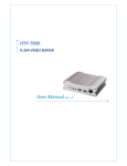
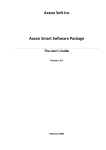
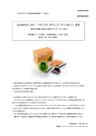
Marshall Electronics VS-101-HDSDI H.264 HD Video Server User Manual Ver. 1.0.2 This page intentionally left blank. Table of Contents Table of Contents ..................................................................................................................... 3 Introduction .............................................................................................................................. 5 About User Manual ......................................................................................................... 5 Feature ............................................................................................................................ 5 Product and Accessories ................................................................................................. 6 Part Names and Functions .............................................................................................. 7 System Modes and Connections .................................................................................... 9 Installation ................................................................................................................................ 12 Connecting Video ............................................................................................................ 12 Connecting Audio ............................................................................................................ 12 Connecting Serial Ports .................................................................................................. 12 Connecting Sensor and Alarm ........................................................................................ 12 Connecting Power ........................................................................................................... 13 Check if It Works ............................................................................................................. 13 System Operation .................................................................................................................... 14 LED Display .................................................................................................................... 14 Remote Video Monitoring ................................................................................................ 15 Initialization of IP Address ............................................................................................... 17 Remote Configuration ............................................................................................................. 18 Encoder Configuration ............................................................................................................ 19 System Configuration ...................................................................................................... 19 Video Configuration ......................................................................................................... 22 Audio Configuration ......................................................................................................... 26 Network Configuration ..................................................................................................... 27 Serial Port Configuration ................................................................................................. 31 Event Configuration ......................................................................................................... 33 Preset Configuration ....................................................................................................... 36 Record Configuration ...................................................................................................... 37 User Configuration........................................................................................................... 46 Decoder Configuration ............................................................................................................ 49 System Configuration ...................................................................................................... 49 Video Configuration ......................................................................................................... 50 Network Configuration...................................................................................................... 51 IP Server Instruction Manual 3 Table of Contents True Manager ............................................................................................................................ 53 True Manager Software ................................................................................................... 53 Server Registration and Removal ................................................................................... 53 Server Connection Management...................................................................................... 56 Server Status Monitoring ................................................................................................. 57 Network and System Diagnostics..................................................................................... 58 F/W Upgrade.................................................................................................................... 61 Remove Configuration and Video Monitoring................................................................... 61 Trouble Shooting ...................................................................................................................... 62 Appendix ................................................................................................................................... 63 Appendix A: Sensor Port & Alarm Port ............................................................................ 63 Appendix B: Serial Port ................................................................................................... 65 Safety Precaution We appreciate your purchase of the VS-101-HDSDI. Before installing the product, please read the following with care. ■■ Make sure to turn off the power before installing VS-101-HDSDI. ■■ Do not install in locations with direct sunlight or in dusty areas. ■■ Make sure to use the product within the temperature and humidity specifications. ■■ Do not operate the product in locations with strong vibrations or magnetic fields. ■■ Do not insert electrically conductive materials in the ventilation hole. ■■ Do not open the product. There are no user serviceable parts inside. ■■ To prevent from overheating, make sure to keep a clearance of at least 4 inches from the ventilation hole. ■■ Make sure the voltage is correct (220V/110V) before connecting the power. 4 IP Server Instruction Manual Introduction About This Manual This User Manual provides information on operating and managing the VS-101-HDSDI. The Manual includes instructions for the installation, operation and configuration of the VS-101-HDSDI as well as troubleshooting tips. Features VS-101-HDSDI is a Video and Audio transmission system that provides HD Video and AAC audio along with remote functions using IP protocol through existing LAN, ADSL/VDSL, and Wireless LAN networks. When encoding the VS-101-HDSDI compresses video and audio data and transmits it. When Decoding the VS-101-HDSDI receives the data and decompresses it. ■■ Video State-of- the art H.264 & MJPEG Compression Algorithm. Compression and Decompression with 18 Resolution formats. : Full HD (1920x1080) ~ CIF(352x240) Wide Range of Video Transmission Rate : 32kbps ~ 8Mbps Various Transmission Mode : CBR, VBR Motion Detection HDMI In/Output HD-SDI In/Output ■■ Audio Multi-Transmission Mode : Unidirectional or Bidirectional stereo audio ■■ Network Static IP & Dynamic IP (DHCP) Support One to One Connection & One to Multiple Connection Multi-Casting Various Protocols support : TCP/IP, UDP, Multicast, DHCP, SMTP, HTTP, SNMP, RTP, RTSP ■■ Serial Data Two serial ports : RS-232, RS-422/485 Various PTZ camera protocols Data pass-through mode : Serial data communication between Encoder - Decoder IP Server Instruction Manual 5 Introduction ■■ Sensor and Alarm Connections to external sensor and alarm devices Event Alarm ■■ USB Connection to an external USB storage for remote access, recording and playback ■■ User Interface Display system status with OSD (On Screen Display) Configuration and upgrade using dedicated program (True Manager) System configuration using Internet Explorer ■■ Reliability Reliable embedded operating system Auto reboot and system recovery after power loss Product and Accessories VS-101-HDSDI Software CD 6 User Manual Screws Power adapter and Cable Brackets IP Server Instruction Manual Introduction Part Names and Functions ■■ Front View No. 1 2 3 4 5 6 7 8 IP Server Instruction Manual Parts LED Audio Input Audio Output HDMI Input HDMI Output USB Port LAN Reset Button Function Display system status Audio Input Audio Output HDMI Video Input HDMI Video Output USB 2.0 100/10-base-T Ethernet Initialization of network setting 7 Introduction ■■ Rear View No. 1 2 3 4 5 6 7 8 8 Parts Power Sensor Alarm RS-422/485 RS-232 Video Output Switch Video Input Function DC +12V power input Sensor Input Alarm or Relay Output Serial port for PTZ control and etc Serial port for PTZ control and etc Composite or HD-SDI Output Composite or HD-SDI Switch - Switch Down: Composite Video - Switch Up : HD-SDI Video Composite or HD-SDI Input IP Server Instruction Manual Introduction System Modes and Connections The VS-101-HDSDI operates as an Encoder or Decoder. The VS-101-HDSDI can be connected in either 1-to-1 fashion where one encoder is connected one decoder or 1-to-many fashion where one encoder is connected to many decoders. Following chart shows data status of video, audio and serial data on each mode. System Mode Encoder Decoder Video Transmit Receive Audio Transmit/Receive Transmit/Receive Serial Data Transmit/Receive Transmit/Receive The System Mode is determined by the video communication status, while Audio and Serial Data modes are always capable of Unidirectional or bidirectional transmission. ■■ Topology Generally, the encoder and decoder are connected in 1-to-1 mode. To support specific situations, 1-to-1 multiple connections are also supported. 1:1 Connection (Unidirectional Transmission) Site Encoder Remote Center →→ Decoder Mostly used configuration is 1 to 1 connection. An encoder is installed at a site where video images can be transmitted and a decoder is installed at a center location to receive and view the video images on monitors. Audio and serial data are transferred in either direction. A decoder and encoder can be connected by setting the encoder’s address at the decoder’s remote IP. IP Server Instruction Manual 9 Introduction ■■ 1:N Connection (Unidirectional Transmission) Encoder →→ Decoder →→ Decoder → → 1 2 Decoder n In this configuration, a site can be monitored from many remote center locations. Although up to ‘n’ decoders can be connected to an encoder, in the real network environment, Maximum connections would be limited by network bandwidth connection Functionally, the CMS (Central Monitoring System) software can replace the decoder. Multicast Mode In the network supporting multicast mode, if Multicast is setup as a system protocol, you can use bandwidth efficiently regardless of the number of decoders. In 1:N connection, a large number of decoders can receive audio and video data from an encoder by using a single streaming transmission. ■■ Relaying Site IP Server Remote Center #1 →→ Decoder Remote Center #2 →→ Decoder In this arrangement, video and audio can be retransmitted from a center to another center. The arrangement is useful when the network bandwidth at the site is limited while there is more than one center wanting to monitor the site. 10 IP Server Instruction Manual Introduction ■■ CMS(Central Monitoring System) Site Remote Center Encoder Site Encoder →→ CMS Remote Center →→ Decoder →→ CMS CMS (Central Monitoring System) is a Windows based remote monitoring program to access multiple encoders for real-time monitoring or control of the encoders and connected cameras. Please refer to CMS User Manual for more information on CMS. IP Server Instruction Manual 11 Installation Connecting Video ■■ Encoder System Connecting the HD Camera Connect the HDMI or HD-SDI output of the HD camera to the Appropriate HDMI or HDSDI Input port of VS-101-HDSDI. For HD-SDI the input dip switch should be set to the UP position Connecting a standard resolution NTSC/PAL Camera Connect the camera to the Video Input port of the VS-101-HDSDI. For standard NTSC/PAL the video input dip switch should be set to the Down position. ■■ Decoder System Connect a monitor to the HDMI or COMPOSITE (HD-SDI) Output of the VS-101-HDSDI. Connecting Audio Audio is bidirectional regardless of the system mode (Encoder or Decoder). If necessary, it can be configured to be transmit-only, receive -only or bidirectional mode ■■ Connect the audio input and output ports to the appropriate audio devices as required. ■■ The Audio I/O is -10dBu unbalanced line level stereo, appropriate microphone or speaker amplification is required. Connecting Serial Ports Two serial ports are provided for remote camera control and PTZ controller receiver. These are connected in connected in 1-to-1 fashion and work in a pass-through mode. This means that commands at a local system’s COM1 port will be transparently passed to the remote system’s COM1 port. Also, a command at a local system COM2 port will pass to the remote system’s COM2 port. Connecting Sensor and Alarm Connect sensor and alarm devices to corresponding terminals as required. 12 IP Server Instruction Manual Installation Connecting Power After confirming the power source, connect power adaptor and connect the 12VDC connector to the VS-101-HDSDI. The system will begin to boot up to the operating mode. Check if it Works Once the power is supplied to the server, it will start booting. The system will boot up to an operating mode after approximately 40-60 seconds. The green LED on the Ethernet port will flash indicating the system is ready. Software provided on the disc called True Manager allows you to check the IP address and other network details of the server. Please refer to the True Manager manual for instructions on how to find the IP address of the server and if required changing it. ■■ Encoder LED Display PWR STATUS LINK DATA Red Green Blinking OFF OFF Above LED status shows that the server is connected but a decoder is not connected. Once the encoder is connected to a decoder, color of “LINK” LED will turn into green color and “ DATA” LED will blink as video and / or audio transmissions occur. ■■ Decoder LED Display PWR STATUS LINK DATA Red Green Blinking OFF Above LED status shows that the Decoder has started without connecting to an encoder. Once an encoder is connected, the color of “LINK” LED will be turned to green and the “DATA” LED will blink as video and / or audio data transmissions occur. IP Server Instruction Manual 13 System Operation ■■ Description of LED LED PWR STATUS State Off Red Green blinking Red Constant change of colors between Red and Green Red blinking LINK Constant change of colors between Green blinking 2 times and Red blinking once Green blinking, Red blinks once every 5 seconds Constant change of colors : Green, Orange, Red color in turn Off Green Red blinking Orange DATA 14 Green Red Off Description Power off Power on Normal operation System failure: Needs diagnostics NTSC/PAL setting does not match with input video signal Failed to obtain IP address in DHCP mode Failed to register on DDNS server Video loss in Encoder system Formatting USB storage device No connection to remote system Connected to a remote system Decoder only: trying to connect to an Encoder Illegal connection (unsupported combination of system modes) Data transmission in progress Data loss No data transmission IP Server Instruction Manual System Operation Remote Video Monitoring There are two ways to view video when the connections are completed between a site and center system. In order for a proper operation, an IP address must be set accordingly. Please refer to True Manager in Chapter 3 or Remote Setting in Chapter 4 for further details. Default ID : admin Default Password : 1234 ■■ Video Monitoring with Decoder System Once the IP address is set in the remote IP address section of the decoder, the decoder system will connect to the encoder systems and start receiving the video images. A monitor must be connected to the decoder in order view the video images. ■■ Video Monitoring using Internet Explorer Open Internet Explorer and enter the encoder’s IP address. The system will ask for confirmation to install Active-X control. Once authorized, the Internet Explorer will start to display video images from the encoder in the Live View window as shown. Default IP Address : http://192.168.10.100 IP Server Instruction Manual 15 System Operation ■■ Video Selection The VS-101-HDSDI is capable of dual streaming. Video Selection allows you to choose Primary Video image or Secondary Video image. Video Image is displayed according to the resolution set in video configuration. When dual streaming is not activated and secondary mode is selected, video will not be displayed. ■■ Screen Size : Adjust screen size ■■ Digital Zoom Max 5x Digital Zoom is available 16 IP Server Instruction Manual System Operation ■■ Focus Near, Focus Far, Auto Focus Adjust the focus ■■ Sensor Input When the sensor on VS-101-HDSDI is triggered, the light turns red. ■■ Alarm Output Indicates the alarm device connected to VS-101-HDSDI is active. ■■ Screen Capture (Snapshot) Capture pictures and store as BMP or JPEG files. ■■ Audio Transfer (Talk) Transfer audio Initialization of IP Address If a VS-101-HDSDI IP address is lost, the unit can be reset to the factory default IP address using the reset button in the back side of the system. 1. While the VS-101-HDSDI is powered, press the reset button and hold for 5 seconds. 2. The system will reboot automatically 3. Once the VS-101-HDSDI reboots the IP address will reset to the system default as below. IP mode Subnet mask Base port IP Server Instruction Manual Fixed IP 255.255.255.0 2222 IP address Gateway HTTP port 192.168.10.100 192.168.10.1 80 17 Remote Configuration Remote Configuration Remote configuration of the server is available by web browser. Enter IP address of the VS-101HDSDI when the live view screen appears as below, Press the Setup button in the screen to set the server. For Remote Setting, the user must be authorized higher than manager level. Enter IP address Press setup button The remote configuration window may be slightly different depending on the system modes (Encoder, Decoder). The general explanation of the configuration in this manual is based on Encoder system and differences according to the modes will be clarified when needed. The configurations are grouped into 9 categories: System, Video, Audio, Network, Serial, Event, Preset, Record and User. Any configuration changes are not applied until Apply button is pressed. Leaving the page without pressing Apply button, any changes in the page will be discarded. 18 IP Server Instruction Manual Encoder Configuration Encoder Configuration While most configuration items are common for Encoder and Decoder mode, there are items which are relevant to specific system mode. All the configuration items for Encoder mode are explained first. Then, items specific only to Decoder mode are described. The sections for Decoder will not include items are common to Encoder mode . System Configuration IP Server Instruction Manual 19 Encoder Configuration ■■ General System Mode Select system Mode: Sets the VS-101-HDSDI to be an Encoder or Decoder. System ID Sets the VS-101-HDSDI ID (Name). The name set is displayed with the video image in the web browser and remote decoder. This is useful to quickly identify feeds from Studio One or another camera in the facility. Language Select the language to be used for web-based configuration ■■ Firmware Firmware version Current firmware version Upgrade After selecting a firmware file in your computer, upgrade the VS-101-HDSDI with the selected firmware file. ■■ Time Start Time Latest system boot date and time Current Time Current date & time: Enter a new date and time and press Set Current Time button to update date & time Time Zone Select time zone of where the system is installed. Depending on the time zone, Daylight Saving Time is adjusted automatically The current time will be displayed on remote software and recording files according to the selected time zone, not the time set on the remote computer. . A time zone is a region of the earth that has uniform standard time, usually referred to as the local time. By convention, time zones compute their local time as an offset from UTC (Coordinated Universal Time). In casual use, GMT (Greenwich Mean Time) can be considered equivalent to UTC. Local time is UTC plus the current time zone offset for the considered location. 20 IP Server Instruction Manual Encoder Configuration Automatically synchronize with NTP server Synchronize system time with an NTP server using NTP (network time protocol). Name of the NTP server should be registered on NTP server Name. The Network Time Protocol (NTP) is a protocol for synchronizing the clocks of computer systems over packet-switched, variable-latency data networks. It is designed particularly to resist the effects of variable latency by using a jitter buffer. ■■ Reboot Reboot Server Pressing Reboot Server button will cause the system to reboot. Do not press the Reboot button unless the server needs a reboot. ■■ Factory Reset Factory Reset Set all settings to the factory default values. System log and user registrations are also cleared. IP Server Instruction Manual 21 Encoder Configuration Video Configuration 22 IP Server Instruction Manual Encoder Configuration ■■ Encode Input Format Select an Input Format. There are three types of input ports; Composite, HD-SDI, HDMI. Select an input format according to the input port type. Resolution Select video compression resolution. Compression resolutions are different depending on input formats. The scaling option is used when compression resolution is different from input compression. Without the scaling option, the input video image will be cut according to compression resolution. When scaling is selected, the input video size will be adjusted to the compression resolution. IP Server Instruction Manual 23 Encoder Configuration Frame rate Determine the maximum number of frames of video images to compress. The frame rate of actually transmitted video can be affected by the network bandwidth limitation Preference Preference in video compression and transmission: With ‘Bit rate’ selected, the video compression will be effected by the „Bit rate value entered. With ‘Quality’ selected, the video compression will be effected by the quality of image selected. Therefore, ‘Bit rate’ and ‘Quality’ corresponds to CBR (Constant Bit rate) and VBR (Variable Bit rate) respectively Quality Selectable video compression quality This selection is available if Preference is set to ‘Quality’ Bit rate Selectable video Bit rate. This selection is available if Preference is set to ‘Bit rate’.. I-Frame Interval Possible values between 0 and 255. There will be no I-frames if 0 is selected. ■■ Dual Encode Use Dual Encode The Selection between H.264 and MJPEG is supported. Secondary Video can be used on Live View window. Dual Compression Algorithm Select Secondary Video compression between H.264 and MJPEG. Maximum resolution is 720 x 480. There are 8 steps for adjusting. If MJPEG is selected, only Quality mode is supported ■■ Motion Detection Use Motion Detection Select Motion Detection function 24 IP Server Instruction Manual Encoder Configuration Motion Detection Area Editing Configure regions for motion detection. Regions of arbitrary shape can be configured by the following steps. 1. Enable Edit item. 2. Select editing Mode. Set is for including cells to motion detection region and Erase is for excluding. 3. Select cells using the right button of the mouse. Multiple cells can be selected conveniently by press and dragging. 4. Press Apply Edited Area to save the editing Sensitivity Set the condition to trigger an event for motion detection. The value determines the sensitivity of the motion detection within a block: the smaller, the more sensitive Information Display System ID and/or server time can be display over the video window in Internet Explorer. Each item can be turn on or off separately, and position also can be configure. This information is displayed after the video is decompressed Burn-in OSD Insert system ID and date/time in the compressed video. System ID and time respectively can be turned on or off in the video. And position and Font size can be selectable. IP Server Instruction Manual 25 Encoder Configuration Audio Configuration ■■ Algorithm Select audio algorithm between G.711 and AAC. ■■ Mode Select audio operation mode Mode Off Tx-Only Rx-Only Tx & Rx Action No operation Transmit only Receive only Transmit and Receive ■■ Input Gain Set audio input gain 26 IP Server Instruction Manual Encoder Configuration IP Server Instruction Manual 27 Encoder Configuration ■■ Local IP mode Two IP modes are supported. Depending on the selected mode, further configuration items will be available as shown in the following chart. IP Mode Fixed IP DHCP Selection Local IP Local Gateway Local Subnet N/A Description Fixed IP address Gateway IP address Subnet mask If you are not familiar with IP addressing please ask your ISP provider or network manager for assistance setting the IP address information. ■■ DNS DNS Set DNS server IP address The Domain Name System (DNS) is a hierarchical naming system for computers, services, or any resource connected to the Internet or a private network. It associates various information with domain names assigned to each of the participants. Most importantly, it translates domain names meaningful to humans into the numerical (binary) identifiers associated with networking equipment for the purpose of locating and addressing these devices worldwide. An often used analogy to explain the Domain Name System is that it serves as the “phone book” for the Internet by translating human-friendly computer host names into IP addresses. For example, www.example.com translates to 208.77.188.166 Port Base Port Network base port is use for communication between systems. In order for the servers and remote systems to be connected together, the port number must be identically set. HTTP Port HTTP port use for web-based connection 28 IP Server Instruction Manual Encoder Configuration RTSP Port RTSP port used for RTSP-based connection ■■ RTSP Authentication If RTSP Authentication is set on the network page, the user should enter the correct user ID and password when any RTSP client is connected. ■■ SNMP Setup for using SNMP (Simple Network Management Protocol) SNMP Listen Port: The port is for connecting external devices when system operates as an SNMP client. SNMP is not used by setting the value to 0. SNMP Trap Destination IP: Set the SNMP Trap Destination IP. SNMP Trap Destination Port: Set the SNMP Trap Destination Port. SNMP is not used by setting the value to 0. Simple Network Management Protocol (SNMP) is used in network management systems to monitor network-attached devices for conditions that warrant administrative attention. It consists of a set of standards for network management including an application layer protocol, a database schema, and a set of data objects. ■■ Multicast Multicast IP The multicast IP address selection range is between 224.0.1.0 and 238.255.255.255. The selection can be used only when media protocol is set to Multicast. The multicast address must be the same for the system to be connected using multicast protocol. ■■ DDNS Select the DDNS (Dynamic DNS) server to use. One of the two servers can be selected. True DNS: True DNS service is used in this mode. Systems can be registered on the website for True DNS service: http://ns1.truecam.net. System will get a domain name of xxx.truecam. net style. Please, refer to user guide document for True DNS service. DynDNS: DynDNS service is used in this mode. Refer www.dyndns.org for details. ID, Password and Domain name are needed when DynDNS is set. IP Server Instruction Manual 29 Encoder Configuration Dynamic DNS is a method, protocol, or network service that provides the capability for a networked device, such as a router or computer system using the Internet Protocol Suite, to notify a domain name server to change, in real time (ad-hoc), the active DNS configuration of its configured host names, addresses or other information, stored in DNS. Check IP Disable: If “Check IP Disable” is selected, IP Server will skip to check its own IP. In Fixed IP mode, the set IP will be registered on DDNS server. In DHCP mode, the Allotted IP will be registered on DDNS server. ■■ Bitrate Control Flow control mode : When there are more than one clients connected to an IP camera(or video server) and some of them do not have enough bandwidth to receive encoded stream fully, it is possible to select the way to stream video to clients in Network page Frame Drop Mode: Frames are dropped on sending routine. Only clients with limited bandwidth are affected by the dropping. Suppression Mode: Video encoding is suppressed. All clients are affected. ■■ Address Info The following network information is displayed (Read only) IP Address: The server own IP address. This information is useful when the server’s IP mode is set to DHCP. Domain Name: In case the server is registered at DDNS server, the registered domain name is displayed. MAC Address: Display the MAC address of the server. In case the server is registered at DDNS server, the MAC address is used in DDNS registration. Connecting: Client IP Addresses that are currently connected to system are listed. (1) Indicates Primary streaming and (0) indicates Secondary streaming. 30 IP Server Instruction Manual Encoder Configuration Serial Port Configuration IP Server Instruction Manual 31 Encoder Configuration ■■ Serial Port Type and Configuration Serial Port type: There are two serial ports, one RS-232 and one RS-422/485 available in the VS-101-HDSDI. Select RS-422 or RS-485 in RS-422/485 port Serial Port Configuration: The serial ports can be configured as follows. Each of the serial ports configurations must be same as the connecting device. Mode Bitrate Data Bits Parity Stop Bit Selection 2400, 4800, 9600, 19200, 38400, 57600, 115200 bps 5, 6, 7, 8 bits NONE, EVEN, ODD bit 1, 2 bit ■■ PTZ PTZ Type: Select the type of PTZ camera or receiver. PTZ ID: Since it is possible to control multiple PTZ cameras or receivers over single control line, each camera or receiver will be assigned with unique ID. Enter PTZ ID of a camera or receiver for control. The ID value range can be between 0 and 255. PTZ Port: Select the serial port used for PTZ camera control. Direct Keyboard Control: A Keyboard controller can be connected directly to the VS-101HDSDI to control zoom and focus ■■ Sensor Type There are two sensor input ports on the VS-101-HDSDI. Each of the sensor ports can be configured to the following. Function OFF NO (Normally Open) NC (Normally Closed) Operation Not used The port is normally open and activated when closed. The port is normally closed and activated when opened. The function of the sensor port is based on the type of the sensor connected. ■■ Sensor Schedule Each sensor port can be enabled or disabled by the day of the week and hour of the day. The Sensor is disabled when the indicated block is colored grey. 32 IP Server Instruction Manual Encoder Configuration Event Configuration IP Server Instruction Manual 33 Encoder Configuration ■■ Local & Remote Event Configuration The event configuration page is where the actions for each event type are configured. The Local section configures the actions for events initiated at the local system and activates local devices. The Remote section configures the actions for events from remote (peer) systems. The following table lists the possible actions for events. Action Beep Alarm1/Alarm2 E-mail FTP Preset Description Outputs beep sound using the buzzer in the system Triggers alarm (relay) port. Sends E-mail to the specified address. AVI file can be attached Upload AVI file to a specified FTP server Moves the PTZ to associated preset position The Sensor1 / Sensor2/ Sensor3 / Sensor4. Configure the actions when the sensor is activated. Multiple actions can be set for a single event. On Video Loss Configure the actions when video input signal is lost. Multiple actions can be set for a single event. On Motion Configure the actions when motion is detected. Multiple actions can be set for a single event. On Disconnect Configure the actions when the link(connection) with peer system is disconnected. Multiple actions can be set for a single event. ■■ Alarm and Beep activation duration Set the duration of alarm or beep activation in case of an event. If it is set to continuous, it will remain in the active state until an operator resets it manually. 34 IP Server Instruction Manual Encoder Configuration ■■ E-mail Notification Specify what information to send, when E-mail is selected as an event action. Server Address: Enter the address for the e-mail SMTP (server). Port: Specify a port for SMTP operation (Port 25 is the default port in SMTP operation. If a different port is configured in the SMTP server, this port needs to be changed accordingly). Sender Address: Enter an account registered in the SMTP server. ID & password: When the server requires authentication, ID and Password of an E-mail account need to be entered. Destination address: Enter Destination address. More than one address can be entered by delimiting comma (,) or semi-colon (;). Destination address can take up to 63 characters. Video Clip Attaching: A video clip stored at the moment of event can be attached as an AVI or JPEG file format. If using dual Encoding, Primary video or Secondary video (H.264 only) can be selected. ■■ FTP Upload Specify the information to upload event information, when FTP is selected as an event action Server Address: Enter the address of the FTP server to receive video files Port: Specify a port for FTP operation (Port 21 is the default port in FTP operation. If a different port is configured in the FTP server, this port needs to be changed accordingly.). ID & password: Enter ID and Password for accessing the FTP server. Upload video: Primary video and Secondary video (H.264 only), JPEG can be selected as an upload method. Continuous upload: Continuous upload “on” allows the video image to be transmitted regularly, regardless of occurrence of events. Upload duration: Specify recording duration of a video clip to be transmitted. Upload interval: Specify transmission interval. Recording duration is not included in transmission interval. For example, if upload interval is 60 seconds and upload duration is 20 seconds, a video clip for 20 seconds is transmitted every 80 seconds. ■■ Event Record Specify duration of recording video generated by events to send through e-mail or upload through FTP. Pre-event Time: Specify the duration of recording before an event happens. Post-event Time: Specify the duration after the event is cleared. Max duration is 30 seconds IP Server Instruction Manual 35 Encoder Configuration Preset Configuration 2) Enter a name Move PTZ camera to the desirable view 4) Save 3) Press set button Configure up to 15 preset positions. Preset function is not available on some PTZ receivers. Make sure to check if your PTZ receiver supports preset. ■■ Preset Configuration Set the PTZ Presets by following the next steps. 1. Move cameras to desired view using PTZ control buttons. 2. Enter Preset name. 3. Press Set button. 4. Once all the presets are set, press Save List button. Move to Preset Position Select a preset from the Preset List and press the Go To button, the camera will move to the selected preset position. 36 IP Server Instruction Manual Encoder Configuration Recording Configuration IP Server Instruction Manual 37 Encoder Configuration USB Device A USB hard disk or memory stick can be used, at least 1GB size is recommended. A device formatted in the EXT3 or FAT32 file system can be used. A disk with either EXT3 or FAT32 file system can be read in a Linux PC. However, only FAT32 files can be read in a Windows PC. When formatting using True Manager the disk will be formatted as EXT3. In order to review files from the device on a Windows PC, you must format the disk in FAT32 using a Windows PC. * Less than 4Mbps of video bit rate is recommend when you record and monitor video at the same time since it may cause frame loss. Disk information and recording setup After connecting a USB device be sure to restart the system. During booting, the system reads status of the disk and initializes it. Once the initialization of a disk is finished, the status of disk is shown on Record page of web-based setup. ■■ Disk Information The status of a disk can be checked from the Disk Manage menu of True Manager as well. 38 IP Server Instruction Manual Encoder Configuration Refer to the chart for checking the status of disk. Disk status Disk error detected No disk Searching Disk information Mounting and Recovering Disk... Disk format needed Unknown disk type detected USB Disk available - (format is recommended) USB Disk available Disk formatting – Start Disk formatting – Progressing…… Disk formatting – Writing inode tables 63/619 Disk formatting – Creating journal…… Disk formatting – Writing Superblocks…… Disk format done, Please wait for reboot. Disk removed or in abnormal state IP Server Instruction Manual Description Error Disk is not connected to the system. Checking the status of disk. Refresh the page and wait until the status is changed. Performing recovery process when disk damage is found. It may take from seconds to minutes for disk recovery. Disk is attached, but the type of the file system is unknown or damaged. Disk is available, but formatting is recommended. Available to be used for recording Disk is being formatted. System should not be turned off during formatting. Disk is detached during operation or there is damage on the file system. If it happens while disk is connected, it is recommended to format the disk. 39 Encoder Configuration ■■ General Use record - On: Recording function in enabled when “On” is selected. - Off: Recording function is disabled when “Off” is selected Select Video: Select the video source from either primary video or secondary video Overwrite: Selects option when the disk is full. If Overwrite is set to Off, the recording stops automatically when there is less than 100MB free space in the disk. If Overwrite is set to On , recording continues by deleting the oldest data first on disk, maintaining free space of 300MB for normal operation. Max File Size: The Max File Size option is for limiting the size of AVI file. If small file size is set, files of small size will be generated while the number of the files will be increased. If recording time is more than 10 minutes, new file will be created even though previous file size is smaller than set max file size. ■■ Event Type Three recording modes are supported in the VS-101-HDSDI: Continuous, Event, Disconnect. Event recording, allows event types to be selected as a record start trigger. Selected event types are used to configure the schedule table. Up to 4 event types can be configured and each event type can be a combination of sensor, video loss and motion event. Pre-event Time: Specify the duration of recording before an event happens. Post-event Time: Specify the duration after the event is cleared ■■ Schedule Table The actual recording mode is determined by the Schedule Table, where recording modes are configured by the day of the week and time of the day. Each of recording mode configures the recording operation as follows: • Record off : The Record function is disabled and no recording will occur. • Continuous : Records continuously • Disconnect: Data is recorded when the system loses the connection to its client (Decoder, CMS/NVR) etc. If one of multiple client systems is disconnected, this doesn’t happen. • Event Type: Initiates Recording when an event configured in the Event Type setting occurs. 40 IP Server Instruction Manual Encoder Configuration Checking status of recording Recording status tally can be shown on the main view page. Recording status can be also shown in True Manager. When data is being recorded, Record column displays ON sign. IP Server Instruction Manual 41 Encoder Configuration Search and Playback ■■ Recorded File Recorded video and audio data are saved as AVI files on the disk. In general, one AVI file is created for an event in case of event-based recording. However, it is possible that data recorded during a series of events happening continuously can be merged to a single AVI file depending on pre/post event time setting. The size of file is limited to 10 ~ 200MB or 10 minutes. In case of continuous recording, AVI files are created in series and the size of each is limited to 10 ~ 200MB or 10 minutes. ■■ Search A file currently being recorded doesn’t appear until it is completed. In case of Continuous recording, a file will be shown after 10 minutes from the start of recording, for a file is generated every 10 minutes. Press Search Page button on the Record setup page. Dates with recording data will be shown as follows. First, choose the date for search and the list of AVI files will be shown. The file name shows the date and time: “Date Begin Time End Time.avi”. Press Root to move back to the page with date list. 42 IP Server Instruction Manual Encoder Configuration ■■ Playback Selecting an AVI file will show a dialog for opening or saving the file. Pressing the Save button will Store the file on the PC. The AVI file can then be played with Windows Media Player. If you press Open in the dialog, the file will be downloaded and played automatically with Media Player. Playback will begin after the entire file has downloaded. Other connections through the web will be disabled IP Server Instruction Manual 43 Encoder Configuration ■■ Deletion If you want to delete recorded files, select the files by checking the item in front of each file and press Delete button. It is possible to delete multiple files at once. Formatting Disk True Manager is used to format a disk which is connected to the system. After connecting True Manager to a system, choose Disk Manage on Tools menu. Check the status of the disk in the dialog and press Disk Format to format the disk. 44 IP Server Instruction Manual Encoder Configuration During formatting a disk, the progress will update on Disk Status item. The system may be rebooted depending on the situation. Once USB Disk available is displayed, it means that formatting is completed successfully. Once formatting is started, it is not allowed to cancel. Even if you close Disk Manage dialog, formatting is continued. Trouble Shooting You may cause damage to the file system if you turn off the power to the VS-101-HDSDI or disconnect the USB memory stick or USB HDD while data is being written. When using FAT32, recording will not occur if the file system is damaged. If this happens, the disk or memory stick should be reformatted using the PC. When using EXT3, if the damage to a file is not serious, it may be recovered automatically. The recovery is executed at initialization of the system. Recording is not performed while recovery is in progress. IP Server Instruction Manual 45 Encoder Configuration User Configuration ■■ User List The User name and privilege level of a user can be specified. User configuration is allowed only by admin user. Max 16 users can be registered and each user can have one of four privileges. Privilege Admin Manager User Guest 46 Allowed Operations All operations All operations except for user configuration Live viewing and PTZ control Live viewing only Remarks User id = admin IP Server Instruction Manual Encoder Configuration ■■ Add User The Add User page appears after the Add button is pressed. A User ID and password needs to be entered and privilege level needs to be selected. A User ID and password consist of alphanumeric string of max 15 characters. Delete User A user is deleted by pressing Delete button. Change Password Pressing the Modify Password button after selecting a user shows a page for changing password. In case of changing the admin password, the old password is checked. IP Server Instruction Manual 47 Encoder Configuration Modify Privilege Level Pressing Modify Privilege button after selecting a user shows a page for changing the users privilege. It is not allowed to change the privilege level of admin user. ■■ Login Policy Skip Login provides for convenient access to the server when authentication is not required. When Skip Login is set to Enable, the login step is skipped. The privilege level after login in this way is determined by the setting of Privilege Level After Login Skipped. 48 IP Server Instruction Manual Decoder Configuration Decoder Configuration The Decoder Configuration contains slightly different menu selections from those in the Encoder Configuration. Differences between the two will be explained in the following Decoder Configuration section. System Configuration By setting System Mode to Decoder in System configuration, the system will reboot and start to work as a Decoder. IP Server Instruction Manual 49 Decoder Configuration Video Configuration ■■ Output format Regardless of the input resolution of the Encoder or IP camera, the Decoder system of VS-101-HDSDI can display the following video formats; Composite NTSC & HDMI 480i (720 x 480) Composite PAL & HDMI 576i (720 x 576) HDMI & HD-SDI 720p60 (1280x720) HDMI & HD-SDI 1080p60 (1920 x 1080) HDMI & HD-SDI 720p50 (1280 x 720) HDMI & HD-SDI 1080i50 (1920 x 1080) ■■ Buffering You can store a maximum of 30 decoded frames by using the buffer before displaying the output. Displaying stored frames is smoother than displaying in real time. However, displaying stored frames causes a delay because of the buffering process. 50 IP Server Instruction Manual Decoder Configuration Network Configuration Network page of Decoder has a section for specifying the remote system to connect. IP Server Instruction Manual 51 Decoder Configuration ■■ Remote Address Address of the remote system to connect ■■ Remote Channel The channel can be selectable when the remote system has more than multiple video channels ■■ Media Protocol Select protocol used for transmission of audio and video data between remote system and decoder. ■■ Use Streaming Server Decoder system has the settings to connect to Encoder or IP Camera via the Streaming Server. To connect to Encoder or IP Camera via Streaming Server, Use Streaming Server of Remote group in Network page should be set to On and information of the Streaming Server (SS) needs to be configured appropriately. SS IP address: IP address of Streaming server SS port: Enter Port number that is set when registering Streaming server. SS ID: Enter Streaming Server ID. SS password: Enter Streaming Server Password. 52 IP Server Instruction Manual True Manager True Manager Software True Manager is a program used for basic configuration, diagnostics and F/W upgrade the VS-101HDSDI video server. True Manager provides the following features: Finding servers on the LAN and assigning IP address Monitoring server status: encoding/decoding, serial, sensor etc. Diagnostic function: PING, network bandwidth measurement, video/audio output, port check, serial port check F/W upgrade Sever Registration and Removal ■■ Server Registration In order to manage servers using True manager, the first step is to register the server. The following steps describe the way to register a server. Select Add Server on Server menu. Enter information for connecting to the server at Add Server dialog. IP Server Instruction Manual 53 True Manager If the server is registered on DDNS server, the domain name can be used instead of an IP address. When the IP address of the server is not known, it is possible to find the IP address of the server using the IP Discovery function. (Please refer to IP Discovery section). Press Add button. ■■ Removal of a server A server can be removed using the following steps. Select a server to remove on Servers tab. The server should be highlighted in blue. Select Remove Server on Server menu. Server Selection ■■ Modification of information for a server Information on a server can be modified on the dialog invoked by selecting Modify Server Info on Server menu. ■■ IP Discovery With IP Discovery function, all servers on the same LAN where the PC executing True Manager is located can be found. Furthermore, it is possible to easily change the IP address of a server .The IP Discovery dialog is invoked by pressing IP Discovery button on the Add Server dialog, it shows all IPservers on the same LAN. 54 IP Server Instruction Manual True Manager If you press Select button after selecting a server, the information on the server is automatically entered on Add Server dialog. Pressing IP Change button after selecting a server invokes a dialog on which IP address of the server can be changed. It is possible to change the IP address of a server which has IP address of different subnet. ■■ Grouping of servers When there are a large numbers of servers, it is convenient to manage servers in several groups. Using Add Group and Remove Group on Group menu, server groups can be created and deleted. Modify Group menu is used to add servers to a group or to remove servers from a group. IP Server Instruction Manual 55 True Manager Server Connection Management ■■ Server connection If there is a check in the box on the first column in Servers (or Channels/Peripheral) tab, True Manager tries to connect to that server. If the server is active and the network the server is on is normal, it will be connected immediately and its State will be changed to Connected. Check box to connect or disconnect server If it fails to connect to the server due to server or network failure, State displays Trying connection. As soon as the server or network has recovered, the server will be connected automatically. That is, True Manager periodically retries the connections to servers with the check box checked ■■ Server disconnection If the check box is unchecked, the connection to the server is released and State displays Disconnected. 56 IP Server Instruction Manual True Manager Server Status Monitoring ■■ Servers tab – General information Servers tab shows general information for a connected server: MAC address, product model, system mode (Type) F/W version and startup time. This information is displayed only for connected servers. ■■ Channels tab - Monitoring of video/audio channel state Channels tab displays the video and audio channel operating parameters of selected servers. Item Displays Ch Conns Cam Motion V-E(kbps) V-E(fps) V-D(kbps) V-D(fps) A-E(kbps) A-D(kbps) Channel no. Number of clients connected to a server (including True Manager) Video loss status Motion status Video encoding bitrate Video encoding framerate Video decoding bitrate Video decoding framerate Audio encoding bitrate Audio decoding bitrate Depending on the system mode, items which are not relevant will always display 0. For example, V-D(kbps) and V-D(fps) are always 0, if the system mode is Encoder. ■■ Peripherals tab – Monitoring of serial, sensor and relay port This function is not available in this product. IP Server Instruction Manual 57 True Manager Network and System Diagnostics True Manager provides various diagnostic features. Connection between two IP-servers, or between IP-server and CMS (Central Monitoring System) is established. Video, audio or serial data are not delivered as configured. Video and/or audio outputs don’t work on selected output port. ■■ Ping test Ping Test dialog can be invoked by selecting Ping Test on Tools menu after selecting a server. Server Executing Ping Destination of Ping Ping test is useful for checking if one or more remote systems are reachable from a server. Up to 4 systems can be registered as the targets of a Ping test, which makes it possible to identify the hop (segment of network) where network failure may happen. For example, local router, remote router and remote Encoder can be pinged from a Decoder simultaneously. 58 IP Server Instruction Manual True Manager ■■ Network test Network Test dialog is invoked by selecting Network Test on Tools menu. Network test can be used for measuring effective bandwidth and/or packet loss rate between a server and PC running True Manager by generating test traffic of constant bitrate. This feature is useful for identifying the reason why video quality appears poorer than expected. TCP protocol can be selected for measuring effective bandwidth, while UDP protocol is appropriate for checking network reliablity. ■■ System test Selecting System Test on the Tools menu displays a dialog box which allows you to test system H/W status,video and audio output functions. IP Server Instruction Manual 59 True Manager System Check System Check tests if H/W components are operational. Board ID and MAC address are displayed. Video Out Check / Display Color Bar It outputs color bars on the video output port. This function works in Decoder or Duplex mode, and is useful for checking if the video output port and external display device is operating normally. Audio Out Check / Play Audio Clip It plays an audio clip and outputs it to the audio output port. This function is useful for checking if the audio output function of a server and the external audio output devices such as amplifier and speaker are operating normally. Serial Loopback Test This function is not available in this product ■■ Viewing server’s log The activity log of a server can be viewed by selecting Log on the Tools menu. ■■ Remote rebooting of a server A server can be rebooted by selecting Reboot on the Tools menu. 60 IP Server Instruction Manual True Manager F/W Upgrade Selecting Update on the Tools menu displays the Firmware upgrade dialog box. Select a server to upgrade (check the check box in Sel column). More than one server can be upgraded simultaneously. Select an upgrade file. Press Upgrade button. Wait until Progress is changed to Upgrade succeeded. Caution: DO NOT power-off the server while the upgrade is in progress. The server may enter an non-recoverable state When the network condition is poor, the upgrade procedure may fail. In such a case, please retry the above procedure after the network condition has recovered. Remove Configuration and Video Monitoring The VS-101-HDSDI provides both web-based Setup and Video Viewing. If Setup on Server menu is selected, Internet Explorer displays the page for remote setup of the server. If Live View is selected on the menu, Internet Explorer displays the video from the server. IP Server Instruction Manual 61 Appendix Appendix A : Sensor and Alarm Port ■■ Sensor Port Terminal Type - Voltage Rating: 150VAC - Current Rating : 2A - Color : Red Sensor Signal Input Type - NO Contact Signals Connection to External Device 62 IP Server Instruction Manual Appendix ■■ Alarm Port Terminal Type - Voltage Rating: 150VAC - Current Rating : 2A Relay Type - Contact Rating : 1A 30VDC - Switching Power : Max 30W 62.5VA - Switching Voltage : Max 60VDC Alarm Signal Output Type - NO/NC Contact Signals Connection to External Device IP Server Instruction Manual 63 Appendix Appendix B : Serial Port ■■ RS-232 Port Port Type -3 PIN -Pin Arrangement -Pin Description RS-422/485 Port Pin NO 1 2 3 Pin Name TX RX GND Description RS232 TX(Transmit) RS232 RX(Receive) Ground Port Type -4 PIN -Pin Diagram -Pin Description Pin NO 1 2 3 4 64 Pin Name RXRX+ TXTX+ Description RS422 RXRS422 RX+ RS422 TX- or RS485 TRXRS422 TX+ or RS485 TRX+ It is selectable by S/W Setup IP Server Instruction Manual Troubleshooting Illegal Connect Error If an unauthorized connection has been established the system will not function properly. Maintaining the unauthorized connection will result in a message to correct the error condition. Illegal connect will appear in such conditions as: 1. When Duplex and Encoder are connected 2. When one Duplex connected to more than one Duplex 3. When a Duplex remote connect to set to ON and Other Duplex tries to establish a connection 4. Incompatible Media protocol between two systems 5. Other unauthorized connections Even if an illegal connect condition occurs, normal operation between systems with authorized connections will not be effected. The color of link LED will change to orange and it blinks and, in case of Decoder or Duplex, ‘illegal connect’ message will be displayed on screen IP Server Instruction Manual 65 Warranty Marshall Electronics warranties to the first consumer that this V-MD171 LCD monitor will, under normal use, be free from defects in workmanship and materials, when received in its original container, for a period of one year from the purchase date. This warranty is extended to the first consumer only, and proof of purchase is necessary to honor the warranty. If there is no proof of purchase provided with a warranty claim, Marshall Electronics reserves the right not to honor the warranty set forth above. Therefore, labor and parts may be charged to the consumer. This warranty does not apply to the product exterior or cosmetics. Misuse, abnormal handling, alterations or modifications in design or construction void this warranty. It is considered normal for a minimal amount of pixels, not to exceed three, to fail on the periphery of the display active viewing area. Marshall Electronics reserves the option to refuse service for display pixel failure if deemed unobtrusive to effective use of the monitor by our technicians. No sales personnel of the seller or any other person is authorized to make any warranties other than those described above, or to extend the duration of any warranties on behalf of Marshall Electronics, beyond the time period described above. Due to constant effort to improve products and product features, specifications may change without notice. 66 This page intentionally left blank. Marshall Electronics, Inc. 1910 East Maple Ave. El Segundo, CA 90245 Tel: (800) 800-6608 / (310) 333-0606 • Fax: 310-333-0688 www.LCDRacks.com • [email protected]