1
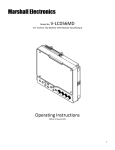
Marshall Electronics VS‐TKC‐100 PTZ Controller User Manual Copyright © December 2011, Marshall Electronics, Inc. All Rights Reserved. This document may not be copied. Trademarks Other trademarks used in this document are registered trademarks or manufacturer or vendor trademarks associated with the products. Disclaimer Product options and specifications can be changed without notice. The information in this manual is furnished for informational use only and should not be construed as a commitment by Marshall Electronics, Inc. Marshall Electronics, Inc. assumes no responsibility or liability for any errors or inaccuracies that may appear in this publication. Page 2 of 28 TABLE OF CONTENTS ___________________________________________________________________________ 1 – Introduction................................................................................. 4 2 – Installation Process............................................................................. 7 3 – Installing the Marshall Video Management Software.............................. 8 4 – Wire the PTZ Camera(s)............................................................................. 10 5 – Set Up VMS for Soft On-Screen PTZ Control…...................................... 11 6 – Connecting TKC-100 and Installing the Driver......................................... 18 7 – Verifying the COM Port TKC-100............................................................... 22 8 – Set Up the Seriel Protocol in VMS…………………………………............. 23 9 – Set Up “PTZ SETUP” on the TKC-100……..……………………............. 25 10 – Test TKC-100 with VM S Software ………………………………............. 26 Page 3 of 28 1 - Introduction About the TKC-100 The Marshall PTZ Controller, TKC-100 is designed as a Hardware Pan, Tilt, Zoom and Focus Controller to work with Marshall Cameras under Marshall Video Management Software Control. It operates under either Battery Power (9V) or AC with the include Marshall AC Adapter (12V). Page 4 of 28 1 - Introduction The TKC-100 is designed to connect to the Computer that hosts the Marshall Video Management Software by USB, both V1.1 and V2.0 are supported. The Marshall Video Management Software is available in a number of versions the only difference between them being how many Cameras can be controlled and viewed at the same time at the Console. VMS-16 VMS-32 VMS-64 VMS-128 Supports 16 Camera on Screen at one time Supports 32 Camera on Screen at one time Supports 64 Camera on Screen at one time Supports 128 Camera on Screen at one time The VMS Software is used to select which Camera is controlled by the TKC-100. The VMS Software offers not only the ability to Monitor the Cameras but also to Record them either by schedule, event or manually. We use a proprietary recording format, which allows us to record all the Streams to one File together with an individual audio track per camera. There is a stand-alone viewer available (VMS Client) without any control features to View an Audio/Video Live Stream or playback a Recording on another Computer. The TKC-100 is designed to work exclusively with the Marshall Video Management Software and does not work with the Live View in Internet Explorer. So even if you are using just one Camera you must have the VMS Software Installed. The choice of the Host Computer and its performance is determined by two factors, the resolution of the Cameras being displayed and how many will displayed at the same time. An installation with 4 Cameras at 720P will need less Computer horsepower than 16 Camera at 1080P. Page 5 of 28 1 - Introduction We will describe the basic features of the Marshall Video Management Software VMS-16, as it is an intrinsic part of using the TKC-100, however, to enjoy all the advanced features of the VMS Software we encourage you to read the VMS User Guide. So this manual will go over an Installation that has one Marshall PTZ Camera, a Computer and a Marshall TKC-100 PTZ Controller. If the Installation had a number of PTZ Cameras and / or Fixed Cameras you only need to add an IP Switch between the Cameras and Computer to accommodate this. RJ45 USB Page 6 of 28 2 – Installation Process The Installation process is broken down into a number of steps. You may of course omit any of these steps if they have already been done: 2-1 2-2 2-3 2-4 2-5 2-6 2-7 2-8 Install the Marshall Video Management Software – VMS-16. Wire a Marshall PTZ Camera with a RJ45 Cable to the Host Computer. Set-up the Camera to work with the Software using the Soft On-Screen PTZ Control. Connect the Marshall TKC-100 PTZ Controller with the supplied USB Cable to the Computer and Install the FTDI CDM Drivers. Check what COM Port the TKC-100 has been assigned. Set-up the Serial Protocol within the Marshall Video Management Software to match the TKC-100 chosen settings. Set-up the “PTZ Setup” on the TKC-100. Test the TKC-100 for Pan, Tilt, Zoom and Focus. To do this installation you will need the following: - Marshall Video Management Software – VMS-16 Marshall TKC-100 FIDI Driver Marshall PTZ Camera Windows Computer XP Professional SP2 or above Marshall TKC-100 PTZ Controller with USB Cable RJ45 Cable Once the Installation and test are complete it is very easy to add or subtract cameras in the future. Page 7 of 28 3 – Installing the Marshall Video Management Software The Marshall Video Management Software is installed on a Windows Computer, which meets the following minimum specifications: Windows XP Professional SP2 or above, Vista Business, Server 2003, Server 2008 or Windows 7 Professional. CPU Intel Pentium 4, 2.4GHz or higher. RAM: 1GB or larger. Network: Ethernet 100Mbps or higher. Graphics: - Graphics memory: 128MB or larger - DirectX9.0c installed - Screen resolution: 1024x768 or larger Note: The above minimum requirements are for normal use with a few cameras. The requirements to support more cameras vary a lot depending on the number of channels, video resolution, framerate, bitrate etc. Please contact Marshall Technical Support to get the recommendation for a specific configuration for supporting a large number of cameras. The Marshall Video Management Software is available in two versions: - VMS Server Software – known as VMS Software VMS Client Software To use the TKC-100 you will need to install the VMS Software. 3-1 3-2 3-3 Find the file folder on the TKC-100 Installation Disk called: “VMS Software”. Double left click on the file “VMS1_06_5111.exe”. The Welcome to the InstallShield Wizard for VMS window will appear, Click “Next”. 3-4 3-5 When localization window appears, select language of your choice, Click “Next”. Choose destination location; typically use the default setting “C\Program Files\VMS\”. Click “Next”. Page 8 of 28 3 – Installing the Marshall Video Management Software 3-6 3-7 3-8 After the install program pane appears, Click “Install” and the install will begin automatically. When the installation is complete, a window will appear stating “Installation Complete”. Do not select “Launch VMS” box as shown below. Click “Finish”. You should find an icon on the desktop that looks like this: Page 9 of 28 4 – Wire the PTZ Camera(s) 4-1 Connect up one or more Marshall PTZ Cameras to the Host Computer with Cat5e/RJ45 Cable. If you have one Camera you may direct connect it to the Host Computer. For more than one PTZ Camera you will need to insert a Switch between the Cameras and the Host Computer as shown below. Cat5e/RJ45 Cat5e/RJ45 Network Switch Cat5e/RJ45 Page 10 of 28 Host Computer with VMS 5 – Set Up VMS for Soft On-Screen PTZ Control The first thing to do is set-up the Host Computer for a Fixed IP Address. Here’s an example using Windows XP Professional: 5-1 Go to Control Panel and open Network Connections. 5-2 When you connect the Switch or Camera, you’re computer find the acquired the device. The computer in this example has a Dual NIC (Network Interface Card) so it can support both a Static and DHCP Network at the same time. 5-3 Right mouse click the Local Area Network Connection, highlight the Internet Protocol (TCP/IP) and click on Properties. 5-4 The Internet Protocol Properties Page will appear to set up for DHCP. 5-5 Select “Use the following IP address”. Page 11 of 28 5 – Set Up VMS for Soft On-Screen PTZ Control 5-6 Enter IP Address 192.168.1.99 and the subnet mask will populate automatically. Click OK, and OK again to close. 5-7 Make sure your PTZ Camera(s) are powered on and connected. 5-8 Launch the VMS Software by double left clicking the VMS Icon on the desktop. 5-9 You will see the Video Management System Login Screen as shown below. The Default Login Credentials are: User ID: admin Password: 1234 If you choose to check the box Automatic Login you will not be asked for a password on launch, but you will need the password to exit VMS. Page 12 of 28 5 – Set-up VMS for Soft On-Screen PTZ Control 5-10 The VMS Home Page appears with a superimposed notice over it “VMS recording failure”. The VMS Application as well as monitoring “Live Streams” from up to 16 sources with audio (VMS-16 Version) can also record them in a Muxed File (also known as Multiplexing) and can play them back in a multi-viewer presentation. The notice means that no hard drive has been allocated to record the streams. We don’t need this feature to set-up and test our PTZ Controller so we will simple click “OK” and close the notice. If interested in using the Record Feature, set up details can be found in the VMS Manual. 5-11 Click ”Setup” on the menu at the top left of the screen and click “Camera”. 5-12 On the Setup Screen, just below the table of cameras which is currently unpopulated, click on the button marked “Discovery”. 5-13 Another window will open with camera(s) IP, Mac Address, Base Port, HTTP Port and IP Address. New cameras will default to the factory IP address of “192.168.10.100”. Because of this common IP address, all new cameras should be connected one at a time to change IP address to a unique address. Page 13 of 28 5 – Set-Up VMS for Soft On-Screen PTZ Control 5-14 First select the Camera or Encoder you wish to change by highlighting in the table. Next click “IP Change” and change to a unique IP address. Example: Change the IP Address to 192.168.1.150 and change the Gateway to 192.168.1.1. To complete, click “Change”. Page 14 of 28 5 – Set-Up VMS for Soft On-Screen PTZ Control 5-15 Now back at the “Setup” page, click “Discovery” again, highlight the Camera or Encoder and click “Select”. 5-16 Now the “Add Camera” window appears. Fill in the following fields; see example with answers in italics. Many fields will auto populate. When finished, click “OK”. Name: Group: Type: Address: Login: Password: Channel: Port: Main Gate 1 TCAM/TCS (Default) Fills in Automatically admin (Default) 1234 (Default) 1 2222 Additional Information: Both “Use PTZ” and “Use audio channel” should be checked. Page 15 of 28 5 – Set-Up VMS for Soft On-Screen PTZ Control 5-17 Now you should be back at the Setup Window and your camera should be in the list. Click “OK”. 5-18 On the Home Page of the VMS Application, the “Main Gate” Camera will auto populate on the Control Pane. Page 16 of 28 5 – Set-Up VMS for Soft On-Screen PTZ Control 5-19 Using the mouse, hold the left button and drag the Main Gate Camera from the control pane to one of the video windows in the multi-viewer. You will see a number of options at the bottom left: “Storage”, “PTZ”, “Audio” and “Video”. Select “PTZ”. 5-20 The Soft PTZ Control allows for Pan and Tilt together with Zoom and Focus. You should have control of the camera now. Dragging the small button inside the circular plate moves the camera to the desired location and the distance from the center sets the speed. Zoom and focus are triggered by pressing (-) or (+) button. Focus provides auto-focus functionality by the button with car sign inside. The speed of zoom and focus operation is controlled by setting the Speed slider. Drag the button We will now connect the TKC-100, PTZ Hardware Controller and Install the Serial Control Drivers. You should close all programs including the VMS Software when doing this. Page 17 of 28 6 – Connecting TKC-100 and Installing the Drivers 6-1 Disconnect the Host Computer from the Internet. 6-2 Copy the TKC-100 folder and contents to your system hard drive, typically “C”. 6-3 Connect the AC Adapter to the TKC-100. Make sure it’s switched off. If not, press the red “ESC/PWR” button with no data on the display. Connect the supplied USB cable to the TKC-100 and the other end to a free USB port on the host computer. USB 6-4 Switch on the TKC-100. 6-5 “Found New Hardware” Balloon appears on the task bar. 6-6 The “Found New Hardware Wizard Opens” to install the “FT232R USB UART”. Page 18 of 28 6 – Connecting TKC-100 and Installing the Drivers 6-7 Select “Install from a list or specific location (Advanced)”. 6-8 Check the boxes as shown and browse to the TKC-100 drivers folder that was put on the “C” drive earlier. Page 19 of 28 6 – Connecting TKC-100 and Installing the Drivers 6-9 The “Completing the Found New Hardware Wizard” Window appears. Click “Finish”. 6-10 Now the “Found New Hardware Wizard Opens” to Install the “USB Serial Port”. 6-11 As before, select “Install from a list or specific location (Advanced).” Page 20 of 28 6 – Connecting TKC-100 and Installing the Drivers 6-12 Check the boxes as shown and browse the TKC-100 drivers folder on the “C” Drive. 6-13 The “Completing the Found New Hardware Wizard” window appears. Click “Finish”. 6-14 The Drivers have now been installed time to check that they have installed correctly. Page 21 of 28 7 – Verifying the COM Port TKC-100 7-1 Open “Device Manager” in Windows XP. Right click “My Computer”. Left Click “Properties”. Left click “Hardware”. Left click “Device Manager”. Expand the tree for both “Universal Serial bus controllers” and “Ports (COM *LPT). You should see as “USB Serial Controller” and “USB Serial Port” (as seen below). 7-2 The TKC-100 has been assigned COM Port 2. Page 22 of 28 8 – Set Up the Serial Protocol in VMS 8-1 The TKC-100 must match the Serial Protocol of the VMS Software. Launch the VMS software. Click ”Setup” from the menu items on the top left of the screen and click “Serial”. 8-2 The following changes need to be made: Port = COM2 (Change) Bitrate = 2400 bps (Change) Data bit = 8 (Default) Parity = None (Default) Stop Bit = 1 (Default) Set Send (PC to camera) to “To all cameras” (Change). Set Received (Camera to PC) to “From selected camera only” (Change). Set the Camera “Main Gate” (in our case) to RS-422/485 (Change). When all the Changes have been made, Click “Apply” and then “OK” Page 23 of 28 8 – Set Up the Serial Protocol in VMS 8-3 Changes have been implemented. Page 24 of 28 9 – Set Up “PTZ SETUP” on the TKC-100 9-1 Set up the TKC-100 Protocol. 9-2 Go to “PTZ Setup Mode” on TKC-100. Select 1 + “SET” and hold for 2 - 3 seconds. 9-3 Use the Joy Stick to make changes. UP/DOWN Scrolls through Menu, LEFT/RIGHT makes Entry Change. You only need to check and maybe change the Baudrate. NOTE: The PTZ Controller must not be in the “DVR WKEY” mode. Push the mouse button to change. Default Password is “0000” Address Change (1~255) - Leave at Default 001 Model Change – Leave at Default - WDS Protocol Change – Leave at Default - PEL-D B Baudrate Change (2.4 kbps - 57.6 kbps) Set for 2.4k Parity Change (None/Even/Odd) Leave at Default – None Prop (ON/OFF) - Proportional Speed Control Leave at Default - ON SAVE SETUP DATA – Right Joy Stick to SAVE EXIT SETUP - Right Joy Stick to EXIT Page 25 of 28 10 – Test TKC-100 with VMS Software 10-1 Launch the VMS application, select a Camera from the Control Pane, and test Pan, Tilt, Zoom and Focus. 10-2 Most features of the TKC-100 are accessible through the Joy Stick, however there are two blue active buttons; top button for manual focus and the lower for zoom as an alternative to twisting the joy stick. Page 26 of 28 Page 27 of 28 ___________________________________________________________________________ Marshall Electronics, Inc. 1910 East Maple Ave. El Segundo, CA 90245 Tel: (800) 800-6608 / (310) 333-0606 Fax (310) 333-0688 www.LCDRacks.com [email protected] User Manual TKC-100 PTZ Controller V1.3 Page 28 of 28 12/20/2011