1
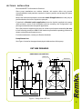
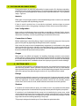
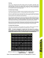
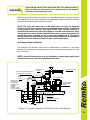
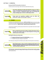
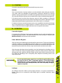
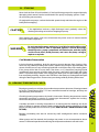
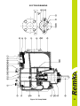
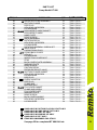
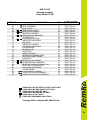
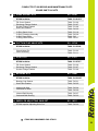
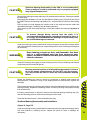
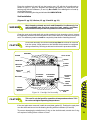
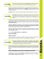
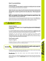
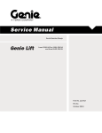
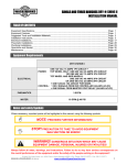
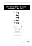
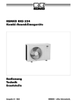
OPERATORS MANUAL
Installation, Operation,
Maintenance and Parts List.
RT 080
TABLE OF CONTENTS
INTRODUCTION.................................................................................
Pg. 03
SECTION A – SAFETY.......................................................................
Pg. 04
SECTION B – INSTALLATION...........................................................
Pg. 05
Pump Dimensions.............................................................
1. PREINSTALLATION INSPECTION...........................................
2. POSITIONING PUMP................................................................
Lifting.................................................................................
Mounting...........................................................................
Clearance..........................................................................
3. SUCTION AND DISCHARGE PIPING......................................
Materials............................................................................
Line Configuration.............................................................
Connections to Pump........................................................
Gauges..............................................................................
4. SUCTION LINES.......................................................................
Fittings...............................................................................
Strainers............................................................................
Sealing..............................................................................
Suction Lines in Sumps.....................................................
Suction Lines Positioning..................................................
5. DISCHARGE LINES..................................................................
Siphoning..........................................................................
Valves...............................................................................
Bypass Lines.....................................................................
6. AUTOMATIC AIR RELEASE VALVE.........................................
Theory of Operation..........................................................
Air Release Valve Installation............................................
7. ALIGNMENT..............................................................................
Coupled Drivers................................................................
V-Belt Drives.....................................................................
Pg. 05
Pg. 06
Pg. 06
Pg. 06
Pg. 06
Pg. 06
Pg. 07
Pg. 07
Pg. 07
Pg. 07
Pg. 07
Pg. 07
Pg. 07
Pg. 07
Pg. 08
Pg. 08
Pg. 08
Pg. 09
Pg. 09
Pg. 09
Pg. 09
Pg. 10
Pg. 10
Pg. 11
Pg. 12
Pg. 12
Pg. 13
SECTION C – OPERATION................................................................
Pg. 14
8. PRIMING...................................................................................
9. STARTING................................................................................
Rotation.............................................................................
10. OPERATION...........................................................................
Lines With a Bypass..........................................................
Lines Without a Bypass.....................................................
Leakage............................................................................
Liquids Temperature and Overheating..............................
Strainer Check..................................................................
Pump Vacuum Check.......................................................
11. STOPPING..............................................................................
Cold Weather Preservation...............................................
12. BEARING TEMPERATURE CHECK......................................
Pg. 14
Pg. 15
Pg. 15
Pg. 15
Pg. 15
Pg. 15
Pg. 15
Pg. 16
Pg. 16
Pg. 16
Pg. 17
Pg. 17
Pg. 17
1
TABLE OF CONTENTS
(Continued)
SECTION D – TROUBLESHOOTING.……….............………………..
Pg. 18
SECTION E – PUMP MAINTENANCE AND REPAIR………..............
Pg. 20
13. PERFORMANCE CURVE………………………………….……
Pump Model ………………………………………………....
PARTS LISTS ........................................................................
Repair Rotating Assembly…………………………………..
PARTS LISTS .........................................................................
REPAIR AND MAINTENANCE KITS…..................................
14. PUMP AND SEAL DISASSEMBLY AND REASSEMBLY…....
Back Cover and Wear Plate Removal……………….....….
Suction Check Valve Removal……………………………..
Rotating Assembly Removal………………………………..
Impeller Removal…………………………………………….
Seal Removal……………………………………………...…
Shaft and Bearing Removal and Disassembly……………
Shaft and Bearing Reassembly and Installation………….
Seal and Installation…………………………......................
Impeller Installation……………………………………….….
Rotating Assembly Installation……….…………………..…
Suction Check Valve Installation…………………………...
Back Cover Installation……………………………………...
15. PRESSURE RELIEF VALVE MAINTENANCE......................
Final Pump Assembly........................................................
16. LUBRICATION........................................................................
Seal Assembly...................................................................
Bearings............................................................................
Power Source....................................................................
NOTES ..................................................................................
SECTION F – WARRANTY..................……….............………………..
Pg. 20
Pg. 21
Pg. 22
Pg. 23
Pg. 24
Pg. 25
Pg. 26
Pg. 26
Pg. 26
Pg. 27
Pg. 28
Pg. 28
Pg. 28
Pg. 29
Pg. 31
Pg. 33
Pg. 34
Pg. 34
Pg. 35
Pg. 35
Pg. 35
Pg. 36
Pg. 36
Pg. 36
Pg. 36
Pg. 37
Pg. 38
PLEASE NOTE: Specifications, measurements and other technical
data contained in this manual is subject to change without notice.
2
INTRODUCTION
This Installation, Operation, and Maintenance manual is designed to help you get the
best performance and longest life from your Remko pump.
This pump is a RT 080 Series, semi-open impeller, self priming centrifugal model with
a suction check valve.
The pump is designed for handling mild industrial corrosives, mud or slurries
containing large entrained solids. The basic material of construction is cast iron, with
ductile iron impeller and steel wearing parts.
If there are any questions regarding the pump or its applications which are not covered
in this manual or in other literature accompanying this unit, please contact your Remko
distributor.
For information or technical assistance on the power source, contact the power source
manufacture's local dealer or representative.
The following are used to alert maintenance personnel to procedures which require
special attention, to those which could damage equipment, and to those which could
be dangerous to personnel:
DANGER!
Immediate hazards which WILL result in severe personal injury or
death. These instructions describe the procedure required and the
injury which will result from failure to follow procedure.
CAUTION!
Hazards or unsafe practices which COULD result in minor personal
injury or product or property damage. These instructions describe
the requirements and the possible damage which could result from
failure to follow the procedure.
NOTE: Instructions to aid in installation, operation, and maintenance or which
clarify a procedure.
3
SECTION A - SAFETY
These warnings apply to RT series basic pumps. Remko has no control over or
particular knowledge of the power source which will be used. Refer to the manual
accompanying the power source before attempting to begin operation.
Before attempting to open or service the pump:
WARNING!
1.
Familiarize yourself with this manual.
2. Disconnect or lock out the power source to ensure that the
pump will remain inoperative.
3. Allow the pump to cool if overheated.
4. Check the temperature before opening any covers, plates, or plugs.
5. Close the suction and discharge valves.
6. Vent the pump slowly and cautiously.
7. Drain the pump
WARNING!
This pump is designed to handle mild industrial corrosives, mud or
slurries containing large entrained solids. Do not attempt to pump
volatile, corrosive, or flammable materials which may damage the
pump or endanger personnel as result of pump failure.
WARNING!
After the pump has been positioned, make certain that the pump and
all piping connections are tight, properly supported and secure
before operation.
WARNING!
Do not operate the pump without the guards in place over the
rotating parts.
Exposed rotating parts can catch clothing, fingers, or tools, causing
severe injury to personnel.
WARNING!
Do not remove plates, covers, gauges, pipe plugs, or fittings from an
overheated pump. Vapour pressure within the pump can cause parts
being disengaged to be ejected with great force. Allow the pump to
cool before servicing.
WARNING!
Do not operate the pump against a closed discharge valve for long
periods of time. If operated against a closed discharge valve,
pump components will deteriorate, and the liquid could come to a
boil, pressure, and cause the pump casing to rupture or explode .
WARNING!
Use lifting and moving equipment in good repair and with
adequate capacity to prevent injuries to personnel or damage to
equipment. Suction and discharge hoses and piping must be
removed before lifting.
4
SECTION B – INSTALLATION
Review all SAFETY information in Section A.
Since pump installations are seldom identical, this section offers only general
recommendations and practices required to inspect, position and arrange the pump
and piping.
Most of the information pertains to a standard static lift application where the pump is
positioned above the level of liquid to be pumped.
If installed in a flooded suction application where the liquid is supplied to the pump
under pressure, some of the information such as mounting, line configuration, and
priming must be tailored to the specific application.
Since the pressure supplied to the pump is critical to performance and safety, be sure
to limit incoming pressure to 50% of the maximum permissible operating pressure as
shown on the pump performance curve.
For further assistance, contact your Remko distributor.
Pump Dimensions
See Figure 1 below for the approximate physical dimensions of this pump.
OUTLINE DRAWING
DIMENSIONS: MILLIMETRES
80MM ANSI 150
70
293.7
80MM ANSI 150
Ø38.1
190.5
431.8
687.4
101.6
Ø17.5
76.2
228.6
284.2
393.7
431.8
668.3
Figure 1. Pump Model RT 080
5
1. PREINSTALLATION INSPECTION
The pump assembly was inspected and tested before from the factory. Before
installation, inspect the pump for damage which may have occurred during shipment.
Check as follows:
a. Inspect the pump for cracks, dents, damaged threads, and other obvious
damage.
b. Check for and tighten loose attaching hardware. Since gaskets tend to shrink
after drying, check for loose hardware at mating surfaces.
c. Carefully read all warnings and cautions contained in this manual or affixed to
the pump, and perform all duties indicated. Note the direction of rotation
indicated on the pump. Check that the pump shaft rotates counterclockwise
when facing the back cover plate assembly/impeller end of the pump.
Only operate this pump in the direction indicate by the arrow on the
pump body and on the accompanying decal. Refer to ROTATION in
OPERATION, Section C.
CAUTION!
a.
Check levels and lubricate as necessary. Refer to LUBRICATION in the
MAINTENANCE AND REPAIR section of this manual and perform duties as
instructed.
b. If the pump and power source have been stored for more than 12 months, some
of the components or lubricants may have exceeded their maximum shelf life.
These must be inspected or replaced to ensure maximum pump service.
c. If the maximum shelf life has been exceeded, or if anything appears to be
abnormal, contact your Remko distributor or the factory to determine the repair
or updating policy. Do not put the pump into service until appropriate action has
been taken.
2. POSITIONING PUMP
Lifting
Use lifting equipment with a capacity of at least 900kg. This pump weighs
approximately 190kg, not including the weight of accessories and base. Customer
installed equipment such as suction and discharge piping must be removed before
attempting to lift.
CAUTION!
The pump assembly can be seriously damaged if the cables or
chains used to lift and move the unit is improperly wrapped around
the pump.
Mounting
Locate the pump in an accessible place as close as practical to the liquid being
pumped. Level mounting is essential for proper operation.
The pump may have to be supported or shimmed to provide for level operation or to
eliminate vibration.
Clearance
When positioning the pump, ensure clearances of 500 mm at both the back cover and
rotating assembly, allowing easy access to the pump interior.
6
3. SUCTION AND DISCHARGE PIPING
Pump performance is adversely affected by increase suction lift, discharge elevation.
And friction losses. See the performance curve and operating range shown on Page 20
to be sure your overall application allows pump to operate within the safe operation
range. -Figure 9.
Materials
Either pipe or hose maybe used for suction and discharge lines: however, the materials
must be compatible with liquid being pumped.
If hose is used in suction lines, it must be the rigid-wall, reinforced type to prevent
collapse under suction. Using piping couplings in suction lines is not recommended.
Line Configuration
Keep suction and discharge lines as straight as possible to minimize friction losses.
Make minimum use of elbows and fittings, which substantially increase friction loss. If
elbows are necessary, use the long radius type to minimize friction loss.
Connections to Pump
Before tightening a connecting flange, align it exactly with the pump port. Never pull a
pipe line into place by tightening the flange bolts and/or couplings.
Lines near the pump must be independently supported to avoid strain on the pump
which could cause excessive vibration, decrease bearing life, and increased shaft and
seal wear. If hose-type lines are used, they should have adequate support to secure
them when filled with liquid and under pressure.
Gauges
Most pumps are drilled and tapped for installing discharge pressure and vacuum
suction gauges. If these gauges are desired for pumps that are not tapped, drill and tap
the suction and discharge lines not less than 500mm from the suction and discharge
ports and install the lines. Installation closer to the pump may result in erratic readings.
4. SUCTION LINES
To avoid air pockets which could affect pump priming, the suction line must be as short
and direct as possible. When operation involves a suction lift, the line must always
slope upward to the pump from the source of the liquid being pumped: if the line slopes
down to the pump at any point along the suction run, air pockets will be created.
Fittings
Suction lines should be the same size as the pump inlet. If reducers are used in suction
lines, they should be the eccentric type, and should be installed with the flat part of the
reducers uppermost to avoid creating air pockets. Valves are not normally used in
suction lines, but if a valve is used, install it with the horizontal to avoid air pockets.
Strainers
If a strainer is furnished with the pump, be certain to use it; any spherical solids which
pass through a strainer furnished with the pump will also pass through the pump itself.
If a strainer is not furnished with the pump, but is installed by the pump user, make
certain that the total area of the openings in the strainer is at least three or four times the
cross section of the suction line, and that the openings will not permit passage of solids
larger than the solids handling capability of the pump.
This pump is designed to handle up to 63 mm diameter spherical solids.
7
Sealing
Since even a slight leak will affect priming, head, and capacity, especially when
operating with a high suction lift; all connections in the suction line should be sealed
with pipe dope to ensure an airtight seal. Follow the sealant manufacturer's
recommendations when selecting and applying the pipe dope. The pipe dope should
be compatible with the liquid being pumped.
Suction Lines in Sumps
If a single suction line is installed in a sump, it should be positioned away from the wall
of the sump at a distance equal to 1 ½ times the diameter of the suction line.
If there is a liquid flow from an open pipe into the sump, the flow should be kept away
from the suction inlet because the inflow will carry air down into the sump, and air
entering the suction line will reduce pump efficiency.
If it is necessary to position inflow close to the suction inlet, install a baffle between the
inflow and the in suction lines, it must be the rigid-wall, reinforced type to prevent
collapse under suction. Using piping couplings in suction lines is not recommended.
Suction inlet at a distance 1 ½ times the diameter of the suction pipe. The baffle will
allow entrained air to escape from the liquid before it is drawn into the suction inlet.
If two suction lines are installed a single sump, the flow paths may interact, reducing the
efficiency of one or both pumps. To avoid this, position the suction inlets so that they are
separated by a distance equal to at least 3 times the diameter of the suction pipe.
Suction Line Positioning
The depth of submergence of the suction line is critical to efficient pump operation.
Figure 2 below shows recommended minimum submergence vs. velocity.
NOTE: The pipe submergence required may be reduced by installing a
standard pipe increaser fitting at the end of the suction line. The larger opening
size will reduce the inlet velocity. Calculate the required submergence using the
following formula based on the increased opening size (area or diameter).
VELOCITY: Meters / Second
m
5.00
4.75
4.50
4.25
4.00
3.75
3.50
3.25
3.00
2.75
2.50
2.25
2.00
1.75
1.50
1.25
1.00
0.75
0.50
0.25
0.00
0.00 0.50 1.00 1.50 2.00 2.50 3.00 3.50 4.00 4.50 5.00
m/sec
VELOCITY (M./SEC.)= FLOW (M./MIN)x21.22 OR FLOW (M³/SEC.)
DIAMETER IN MM²
AREA IN M²
Figure 2. Recommended Minimum Suction Line Submergence vs. Velocity
8
5. DISCHARGE LINES
Siphoning
Do not terminate the discharge line at a level lower than of the liquid being pumped
unless a siphon breaker is used in the line. Otherwise, a siphoning action causing
damage to the pump could result.
VALVES
If a throttling valve is desired in the discharge line, use a valve as large as the largest
pipe to minimize friction losses. Never install a throttling valve in a suction line.
With high discharge heads, it is recommended that a throttling valve and a system
check valve be installed in the discharge line to protect the pump from excessive shock
pressure and reverse rotation when it is stopped.
CAUTION!
If the application involves a high discharge head, gradually close the
discharge throttling valve before stopping the pump.
Bypass Lines
Self-priming pumps are not air compressors. During the priming cycle, air from the
suction line must be vented to atmosphere on the discharge side. If the discharge line is
open, this air a check valve has been installed in the discharge line, the discharge side
of the pump must be opened to atmospheric pressure through a bypass line installed
between the pump discharge an the check valve. A self-priming centrifugal pump will
not prime if there is sufficient static liquid head to hold the discharge check valve
closed.
NOTE: The bypass line should be sized so that it does not affect pump
discharge capacity; however, the bypass line should be at least 25mm in
diameter to minimize the chance of plugging.
In low discharge head applications (less than 9 meters), it is recommended that the
bypass line be run back to the wet well, and locate 150mm below the water level or cutoff point of the level pump. In some installations, this bypass line may be terminated
with a 1800-2400mm length of 32mm ID. Smooth-bore hose; air and liquid vented
during the priming process will then agitate the hose and break up any solids, grease,
or other substances likely to cause clogging.
CAUTION!
A bypass line that is returned to a wet well must be secured against
being drawn into the pump suction inlet.
It is also recommended that pipe unions be installed at each 90º elbow in a bypass line
to ease disassembly and maintenance.
In high discharge head applications (more than 9 metres), an excessive amount of
liquid may be bypassed and forced back to the wet well under the full working pressure
of the pump; this will reduce overall pumping efficiency. Therefore, it is
recommended that an Automatic Air Release Valve be installed in the bypass
line.
Automatic Air Release Valves are reliable, and require minimum maintenance. See
AUTOMATIC AIR RELEASE VALVE in this section for installation and theory of
operation of the Automatic Air Release Valve. Contact your Remko distributor for
selection of an Automatic Air Release Valve to fit your application.
9
If the installation involves a flooded suction such as below-ground lift station. A pipe
union and manual shut-off valve may be installed in the bleed line to allow service of the
valve without shutting down the station, and to eliminate the possibility of flooding. If a
manual shut-off valve is installed anywhere in the air release piping, it must be a fullopening ball type valve to prevent plugging by solids.
DANGER!
If a manual shut-off valve is installed in a bypass line, it must not be
left closed during operation. A closed manual shut-off valve may
cause a pump which has lost prime to continue to operate without
reaching prime, causing dangerous overheating and possible
explosive rupture of the pump casing. Personnel could be severely
injured.
Allow an over-heated pump to cool before servicing. Do not remove plates,
covers, gauges, or fittings from an overheated pump. Liquid within the pump
can reach boiling temperatures, and vapour pressure within the pump can cause
parts being disengaged to be ejected with great force. After the pump cools,
drain the liquid from the pump by removing the casing drain plug. Use caution
when removing the plug to prevent injury to personnel from hot liquid.
6. AUTOMATIC AIR RELEASE VALVE
When properly installed and correctly adjusted to the specific hydraulic operating
conditions of the application, the Automatic Air Release Valve will permit air to escape
through the bypass line, and then close automatically when the pump is fully primed
and pumping at full capacity.
Theory of Operation
Figures 3 and 4 below show a cross-sectional view of the Automatic Air Release Valve,
and a corresponding description of operation.
Figure 3. Valve in Open Position
Figure 4. Valve in Closed Position
During the priming cycle, air from the pump casing flows through the bypass line, and
passes through the Air Release valve to the wet well (Figure 3).
When the pump is fully primed, pressure resulting from flow against the valve
diaphragm compresses the spring and closes the valve (Figure 4). The valve will
remain closed, reducing the bypass of liquid to 3.8 to 19 litres per minute, until the
pump loses it's prime or stops.
10
WARNING!
Some leakage 3.8 to 19 litres per minute will occur when the valve is
fully closed. Be sure the bypass line is directed back to the wet well
or tank to prevent hazardous spills.
When the pump shuts down, the spring returns the diaphragm to its original position.
Any solids that may have accumulated in the diaphragm chamber settle to the bottom
and are flushed out during the next priming cycle.
NOTE: The valve will remain open if the pump does not reach its designed
capacity or head. Valve closing pressure is dependent upon the discharge head
of the pump at full capacity. The range of the valve closing pressure is
established by the tension rate of the spring as ordered from the factory. Valve
closing pressure can be further adjusted to the exact system requirements by
moving the spring retaining pin up or down the plunger rod to increase or
decrease tension on the spring. Contact your Remko distributor for information
about an Automatic Air Release Valve for your specific application.
Air Release Valve installation
The Automatic Air Release Valve must be independently mounted in a horizontal
position and connected to the discharge line of the self-priming centrifugal pump (see
Figure 5 below).
NOTE: If the Air Release Valve is to be installed on a staged pump application,
contact the factory for specific installation instructions.
INSTALL AI R RELEASE VALVE
IN HORIZONTAL POSITION
90° LONG
RADIUS
ELBOW
DISCHARGE PIPE
°
BLEED LINE
25MM DIA. MIN.
(CUSTOMER
FURNISHED)
EXTEND
152MM
BELOW LIQUID
LEVEL SURFACE
DISCHARGE PIPE
CLEAN-OUT
COVER
SUPPORT
BRACKET
SELF-PRINING
CENTRIFUGAL
PUMP
SUCTION
LINE
DRAIN LINE
WET WELL OR SUMP
Figure 5. Typical Automatic Air Release Valve Installation
11
The valve inlet must be installed between the pump discharge port and the nonpressurized side of the discharge check valve. The valve inlet is it at the large end of
the valve body, and is provided with standard 25mm NPT pipe threads.
The valve outlet is located at the opposite end of the valve, and is also equipped with
standard 25mm NPT pipe threads. The outlet should be connected to a bleed line
which slopes back to the wet well or sump. The bleed line must be the same size as the
inlet piping, or larger. If piping is used for the bleed line, avoid the use of elbows
whenever possible.
NOTE: It is recommended that each Air Release Valve be fitted with an
independent bleeder line directed back to the wet well. However, if multiple airs
Release Valves are installed in a system, the bleeder lines may be directed to a
common manifold pipe. Contact your Remko distributor for information about
installation of an Automatic Air Release Valve for your specific application.
7. ALIGNMENT
The alignment of the pump and its power source is critical for trouble-free mechanical
operation. In either a flexible coupling or V-belt driven system, the driver and pump
must be mounted so that their shafts are aligned with and parallel to each other. It is
imperative that alignment be checked after the pump and piping are installed, and
before operation.
NOTE: Check Rotation, Section C, before alignment of the pump.
When mounted at the Remko factory, driver and pump are aligned before shipment.
Misalignment will occur in transit and handling. Pumps must be checking alignment,
tighten the foundation bolts. The pump casing feet and/or pedestal feet, and the driver
mounting bolts should also be tightly secured.
WARNING!
When checking alignment, disconnect the power source to ensure that
the pump will remain inoperative.
CAUTION!
Adjusting the alignment in one direction may alter the alignment in
another direction. Check each procedure after altering alignment.
Coupled Drives
When using couplings, the axis of the power source must be aligned the axis of the
pump shaft in both the horizontal and vertical planes. Most couplings require a specific
gap or clearance between the driving and the driven shafts. Refer to the coupling
manufacturer's service literature.
Align spider insert type couplings by using calipers to measure the dimensions on the
circumference of the outer ends of the coupling hub every 90 degrees. The coupling is
in alignment when the hub ends are the same distance apart at all points (see Figure 6
page 13).
12
Figure 6. Aligning Spider Type Couplings
Figure 7. Aligning Non-Spider
Type Couplings
Align non-spider type couplings by using a feeler gauge or taper gauge between the
couplings halves every 90 degrees. The coupling is in alignment when the hubs are the
same distance apart at all points (see Figure7 above).
Check parallel adjustment by laying a straightedge across both coupling rims at the top,
bottom, and side. When the straightedge rests evenly on both halves of the coupling, the
coupling is in horizontal parallel alignment. If the coupling is misaligned use a feeler
gauge between the coupling and the straightedge to measure the amount of
misalignment.
V-Belt Drives
When using V-belt drives, the power source and the pump must be parallel. Use a
straightedge along the sides of the pulleys to ensure that the pulleys are properly
aligned (see Figure 8 below). In drive systems using two pr more belts, make certain
that the belts are a matched set; unmatched sets will cause accelerated belt wear.
MISALIGNED: SHAFTS
NOT PARALLEL
MISALIGNED: SHAFTS
NOT IN LINE
ALIGNED: SHAFTS
PARALLEL AND
SHEAVES IN LINE
Figure 8. Alignment of V-Belt Driven Pumps
Tighten the belts in accordance with the belt manufacturer's instructions. If the belts are
too loose, they will slip; if the belts are too tight, there will be excessive power loss and
possible bearing failure. Select pulleys that will match the proper speed ratio; over
speeding the pump may damage both pump and power source.
DANGER!
Do not operate the pump without the guard in place over the rotating
parts. Exposed rotating parts can catch clothing, fingers, or tools,
causing severe injury to personnel.
13
SECTION C – OPERATION
Review all SAFETY information in Section A.
Follow instructions on all tags, labels and decals attached to the pump.
WARNING!
This pump is designed to handle mild industrial corrosives, mud or
slurries containing large entrained solids. Do not attempt to pump
volatile; corrosive, or flammable liquids which may damage the
pump or endanger personnel as a result of pump failure.
CAUTION!
Pump speed and operating conditions must be within the
performance range shown on page 20 - figure 9.
8. PRIMING
Install the pump and piping as describe in INSTALLATION. Make sure that the piping
connections are tight, and that the pump is securely mounted. Check that the pump is
properly lubricated (see LUBRICATION in MAINTENANCE AND REPAIR).
This pump is self-priming, but the pump should never be operated unless there is liquid
in the pump casing.
CAUTION!
Never operate this pump unless there is liquid in the pump casing.
The pump will not prime when dry. Extend operation of a dry pump
will destroy the seal assembly.
Add liquid to the pump casing when:
1. The pump is being put into service for the first time.
2. The pump has not been used for a considerable length of time.
3. The liquid in the pump casing has evaporated.
Once the pump casing has been filled, the pump will prime and reprime as necessary.
WARNING!
After filling the pump casing, reinstall and tighten the fill plug. Do not
attempt to operate the pump unless all connecting piping is securely
installed. Otherwise, liquid in the pump forced out under pressure
could cause injury to personnel.
To fill the pump, remove the pump casing fill cover or fill plug in the top of the casing,
and add clean liquid until the casing is filled. Replace the fill cover or fill plug before
operating the pump.
14
9. STARTING
Consult the operations manual furnished with the power source.
Rotation
The correct direction of pump rotation is counterclockwise when facing the impeller.
The pump could be damaged and performance adversely affected by incorrect
rotation. If pump performance is not within the specified limits (see the curve on page
20), check the direction of power source rotation before further troubleshooting (figure 9).
If an electric motor is used to drive the pump, remove V-belts, couplings, or otherwise
disconnect the pump from the motor before checking motor rotation. Operate the motor
independently while observing the direction of the motor shaft, or cooling fan.
If rotation is incorrect on a three-phase motor, have a qualified electrician interchange
any of the phase wires to change direction. If rotation is incorrect on a single-phase
motor, consult the literature supplied with the motor for specific instructions.
10. OPERATION
Lines with a Bypass
If an Automatic Air Release Valve has been installed, the valve will automatically open
to allow the pump to prime, and automatically close after priming is complete (see
INSTALLATION for Air Release Valve operation.
Lines without a Bypass
Open all valves in the discharge line and start the power source. Priming is indicated by
a positive reading on the discharge pressure gauge or by a quieter operation. The
pump may not prime immediately because the suction line must first fill with liquid. If the
pump fails to prime within five minutes, stop it and check the suction line for leaks.
After the pump has been primed, partially close the discharge line throttling valve in
order to fill the line slowly and guard against excessive shock pressure which could
damage pipe ends, gaskets, sprinkler heads, and any other fixtures connected to the
line. When the discharge line is completely filled, adjust the throttling valve to the
required flow rate.
WARNING!
Do not operate the pump against a closed discharge throttling valve
for long periods of time. If operated against a closed discharge
throttling valve, pump components will deteriorate, and the liquid
could come to a boil, build pressure, and cause the pump casing to
rupture or explode.
Leakage
No leakage should be visible at pump mating surfaces, or at pump connections or
fittings. Keep all line connections and fittings tight to maintain maximum pump
efficiency.
15
Liquid Temperature and Overheating
The maximum liquid temperature for this pump is 71º C. Do not apply it at a higher
operating temperature.
Overheating can occur if operated with the valves in the suction or discharge lines
closed. Operating against closed valves could bring the liquid to a boil, build pressure,
and cause the pump to rupture or explode. If overheating occurs, stop the pump and
allow it to cool before servicing it. Refill the pump casing with cool liquid.
DANGER!
Allow an over-heated pump to cool before servicing. Do not remove
plates, covers, gauges, or fittings from an overheated pump. Liquid
within the pump can reach boiling temperatures, and vapour
pressure within the pump can cause parts being disengaged to be
ejected, with great force. After the pump cools, drain the liquid from
the pump by removing the casing drain plug. Use caution when
removing the plug to prevent injury to personnel from hot liquid.
As safeguard against rupture or explosion due to heat, this pump is equipped with a
pressure relief valve which will open if vapour pressure within the pump casing reaches
a critical point. If overheating does occur, stop the pump immediately and allow it to
cool before servicing it. Approach any overheated pump cautiously. It is recommended
that the pressure relief valve assembly be replaced at each overhaul, or any time the
pump casing overheats and activates the valve. Never replace this valve with a
substitute which has not been specified or provided by Remko.
Strainer Check
If a suction strainer has been shipped with the pump or installed by the user, check the
strainer regularly, and clean it as necessary. The strainer should also be checked if
pump flow rate begins to drop. If a vacuum suction gauge has been installed, monitor
and record the readings regularly to detect strainer blockage.
Never introduce air or steam pressure into the pump casing or piping to remove a
blockage. This could result in personal injury or damage to the equipment. If back
flushing is absolutely necessary, liquid pressure must be limited to 50% of the
maximum permissible operating pressure show on the pump performance curve.
Pump Vacuum Check
With the pump inoperative, install a vacuum gauge in the system, using pipe dope on
the threads. Block the suction line and start the pump. At operating speed the pump
should pull a vacuum of 508mm or more of mercury. If it does not, check for air leaks in
the seal, gasket, or discharge valve.
Open the suction line, and read the vacuum gauge with the pump primed and at
operation speed. Shut off the pump. The vacuum gauge reading will immediately drop
proportionate to static suction lift, and should then stabilize. If the vacuum reading falls
off rapidly after stabilization, an air leak exists. Before checking for the source of the
leak, check the point of installation of the vacuum gauge.
16
11. STOPPING
Never halt the flow of liquid suddenly. If the liquid being pumped is stopped abruptly,
damaging shock waves can be transmitted to the pump and piping system. Close
all connecting valves slowly.
On engine driven pumps, reduce the throttle speed slowly and allow the engine to idle
briefly before stopping.
CAUTION!
If the application involves a high discharge head, gradually close the
discharge throttling valve before stopping the pump.
After stopping the pump, lock out or disconnect the power source to ensure that the
pump will remain inoperative.
WARNING!
Do not operate the pump against a closed discharge throttling valve
for long periods of time. If operated against a closed discharge
throttling valve, pump components will deteriorate, and the liquid
could come to a boil, build pressure, and cause the pump casing to
rupture or explode.
Cold Weather Preservation
In below freezing conditions, drain the pump to prevent damage from freezing. Also,
clean out any solids by flushing with a hose. Operate the pump for approximately one
minute; this will remove any remaining liquid that could freeze the pump rotating parts.
If the pump will be idle for more than a few hours, or if it has been pumping liquids
containing a large amount of solids, drain the pump, and flush it thoroughly with clean
water. To prevent large solids from clogging the drain port and preventing the pump
from completely draining, insert a rod or stiff wire in the drain port, and agitate the liquid
during the draining process. Clean out any remaining solids by flushing with a hose.
12. BEARING TEMPERATURE CHECK
Bearings normally run at higher than ambient temperatures because of heat generated
by friction. Temperatures up to 71º C are considered normal for bearings, and they can
operate safely to at least 82º C.
Checking bearing temperatures by hand is inaccurate. Bearing temperatures can be
measured accurately by placing a contact-type thermometer against the housing.
Record this temperature for future reference.
A sudden increase in bearing temperature is a warning that the bearings are at the
point of failing to operate properly. Make certain that the bearing lubricant is of the
proper viscosity and at the correct level (see LUBRICATION in MAINTENANCE AND
REPAIR).
Bearing overheating can also be caused by shaft misalignment and/or excessive
vibration.
When pumps are first started, the bearings may seem to run at temperatures above
normal. Continued operation should bring the temperatures down to normal levels.
17
SECTION D - TROUBLESHOOTING
Review all SAFETY information in Section A.
Before attempting to open or service the pump:
WARNING!
TROUBLE
1. Familiarize yourself with this manual.
2. Lock out or disconnect the power source to ensure that the
pump will remain inoperative.
3. Allow the pump to cool if overheated.
4. Check the temperature before opening any covers, plates, or
plugs.
5. Close the suction and discharge valves.
6. Vent the pump slowly and cautiously.
7. Drain the pump.
POSSIBLE CAUSE
PUMP FAILS Not enough liquid in casing.
TO PRIME
PROBABLE REMEDY
Add liquid to casing. See PRIMING.
Suction check valve contaminated or
damaged.
Clean or replace check valve.
Air leak in suction line.
Correct leak.
Lining of suction hose collapsed.
Replace suction hose.
Leaking or worn seal or pump gasket.
Check pump vacuum. Replace leaking
or worn seal or gasket.
Suction lift or discharge head too high. Check piping installation and install
bypass line if needed.
See INSTALLATION.
EXCESSIVE
NOISE
Strainer clogged.
Check strainer and clean if necessary.
Cavitation in pump.
Reduce suction lift and/or friction losses
in suction line. Record vacuum and
pressure gauge readings and consult
local representative or factory.
Pumping entrained air.
Locate and eliminate source of air bubble.
Pump or drive not securely mounted.
Secure mounting hardware.
Impeller clogged or damaged.
Clean out debris; replace damaged parts.
BEARINGS Bearing temperature is high, but within Check bearing temperature regularly to
monitor any increase.
RUN TOO HOT limits.
Low or incorrect lubricant.
Check for proper type and level of
lubricant.
Suction and discharge lines not properly Check piping installation for proper
supported.
support.
Drive misaligned.
Align drive properly.
18
TROUBLE
POSSIBLE CAUSE
PUMP STOPS Air leak in suction line.
OR FAILS TO
DELIVER
Lining of suction hose collapsed.
RATED FLOW
OR PRESSURE
PUMP
REQUIRES
TOO MUCH
POWER
PROBABLE REMEDY
Correct leak.
Replace suction hose.
Leaking or worn seal or pump gasket.
Check pump vacuum. Replace leaking
or worn seal or gasket.
Strainer clogged.
Check strainer and clean if necessary.
Suction intake not submerged at
proper level or sump too small.
Check installation and correct submergence as needed.
Impeller or other wearing parts worn
or damaged.
Replace worn or damaged parts. Check
that impeller is properly centred and
rotates.
Impeller clogged.
Free impeller of debris.
Pump speed too slow.
Check driver output; check belts or
couplings for slippage.
Discharge head too high.
Install bypass line.
Suction lift too high.
Measure lift with vacuum gauge. Reduce
lift and/or friction losses in suction line.
Pump speed too high
Check driver output; check that sheaves
or motor rpm are correctly sized.
Discharge head too low.
Adjust discharge valve.
Liquid solution too thick.
Dilute if possible.
Bearing(s) frozen.
Disassemble pump and check bearing(s).
PUMP CLOGS Liquid solution too thick.
FREQUENTLY
Dilute if possible.
Discharge flow too slow.
Open discharge valve fully to increase
flow rate, and run power source at
maximum governed speed.
Suction check valve or foot valve
clogged or binding.
Clean valve.
19
SECTION E – PUMP MAINTENANCE AND REPAIR
MAINTENANCE AND REPAIR OF THE WEARING PARTS OF THE PUMP WILL
MAINTAIN PEAK OPERATING PERFORMANCE
13. PERFORMANCE CURVE
.
STANDARD PERFORMANCE FOR PUMP MODEL RT 080
(m)
40
36
11.2 KW
Operating Range
2150 RPM
30% 35%
40%
45%
48%
50%
2050
1950
32
1850
24
7.5
1750
48%
15.0 KW
1650
5.5
TOTAL HEAD - Remko RT 080
1550
20
1450
16
3.7
1350
1250
12
1150
08
04
1.5
950
850
750
650
00
00
00
(m)
10
08
06
04
02
00
45%
2.2
1050
NPSH @ 2150 RPM
0.75
02
10
04
06
20
08
10
30
12
40
14
50
16
60
18
20
70
22
80
24
26
90
28
100
30
110
32
NPSH - Net Positive Suction Head
28
l/s
m3/h
FLOW RATE - Remko RT 080
Figure 9. Pump Performance Curve
Based on 21º C clear water at sea level with minimum suction lift. Since pump
installations are seldom identical, your performance may be different due to such
factors as viscosity, specific gravity, elevation, temperature, and impeller trim.
CAUTION!
Pump speed and operating condition points must be within the continuous
performance range shown on the curve.
20
SECTION DRAWING
Figure 10. Pump Model
21
PARTS LIST
Pump Model RT 080
ITEM NO.
01
02
03
04
05
06
07
08
09
10
11
12
13
14
15
16
17
18
19
20
21
22
23
24
25
26
27
28
29
30
31
32
33
34
35
36
37
38
39
40
41
42
43
PART NAME
PUMP CASING
REPAIR ROTATING ASSEMBLY
SUCTION FLANGE
PIPE PLUG
HEX HEAD CAPSCREW
LOCKWASHER
DISCHARGE FLANGE GASKET
DISCHARGE FLANGE
NAME PLATE
DRIVE SCREW
VALVE ASSEMBLY
ROTATION DECAL
HEX HEAD CAPSCREW
LOCKWASHER
ROTATING ASSEMBLY SCREW SET
WEAR PLATE
CASING DRAIN PLUG
O-RING BACK COVER
HEX NUT
LOCKWASHER
INSPECTION COVER BOLT
STUD
BACK COVER PLATE ASSEMBLY
WARNING PLATE
DRIVE SCREW
CAUTION DECAL
PRESSURE RELIEF VALVE
SUCTION FLANGE GASKET
HEX HEAD CAPSCREW
LOCKWASHER
PIPE PLUG
CHECK VALVE PIN
PIPE PLUG
CLAMP BAR
MACHINE BOLT
FILL COVER GASKET
CLAMP BAR SCREW
FILL COVER PLATE
WARNING PLATE
DRIVE SCREW
BACK COVER HANDLE
HEX HEAD CAPSCREW
LOCKWASHER
QTY
PART NUMBER
01
01
01
01
04
04
01
01
01
04
01
01
04
04
04
01
01
01
02
02
02
02
01
01
04
01
01
01
04
04
01
01
01
01
02
01
01
01
01
02
02
04
04
T080 - PU 01 - CI
T080 - PU 02 T080 - PU 03 T080 - PU 04 T080 - PU 05 T080 - PU 06 T080 - PU 07 T080 - PU 08 T080 - PU 09 T080 - PU 10 T080 - PU 11 T080 - PU 12 T080 - PU 13 T080 - PU 14 T080 - PU 15 T080 - PU 16 T080 - PU 17 T080 - PU 18 T080 - PU 19 T080 - PU 20 T080 - PU 21 T080 - PU 22 T080 - PU 23 T080 - PU 24 T080 - PU 25 T080 - PU 26 T080 - PU 27 T080 - PU 28 T080 - PU 29 T080 - PU 30 T080 - PU 31 T080 - PU 32 T080 - PU 33 T080 - PU 34 T080 - PU 35 T080 - PU 36 T080 - PU 37 T080 - PU 38 T080 - PU 39 T080 - PU 40 T080 - PU 41 T080 - PU 42 T080 - PU 43 -
AVAILABLE IN SUCTION FLAP VALVE KIT ONLY
AVAILABLE IN PUMP GASKET KIT ONLY
AVAILABLE IN PORT KIT ONLY
AVAILABLE IN BEARING KIT ONLY
AVAILABLE AS SET ONLY
ITEMS RECOMMENDED FOR STOCK
See page 25 for completed RT 080 Kit Lists
22
SECTION DRAWING
DRIVE END VIEW
SEAL AREA DETAIL
Figure 11. Repair Rotating Assembly
23
PARTS LIST
Rotating Assembly
Pump Model RT 080
ITEM NO.
01
02
03
04
05
06
07
08
09
10
11
12
13
14
15
16
17
18
19
20
21
22
23
24
25
26
27
28
29
PART NAME
IMPELLER
SEAL ASSEMBLY
SEAL PLATE
INBOARD OIL SEAL
SEAL PLATE GASKET
BEARING HOUSING
INBOARD BALL BEARING
VENTED PLUG
OUTBOARD OIL SEAL
IMPELLER CAPSCREW
AIR VENT
IMPELLER WASHER
HEX HEAD CAPSCREW
LOCKWASHER
BEARING CAP
SHAFT KEY
IMPELLER SHAFT
BEARING RETAINING RING
OIL LEVEL SIGHT GLASS
PIPE PLUG
BEARING CAP GASKET
OUTBOARD BALL BEARING
BEARING HOUSING DRAIN PLUG
SEAL CAVITY DRAIN PLUG
HEX HEAD CAPSCREW
LOCKWASHER
O-RING SHAFT SLEEVE
O-RING ROTATING ASSEMBLY
IMPELLER ADJUSTING SHIM SET
QTY
PART NUMBER
01
01
01
01
01
01
01
01
01
01
01
01
04
04
01
01
01
01
01
01
01
01
01
01
04
04
01
01
01
T080 - RO 01 - CI
T080 - RO 02 T080 - RO 03 T080 - RO 04 T080 - RO 05 T080 - RO 06 T080 - RO 07 T080 - RO 08 T080 - RO 09 T080 - RO 10 T080 - RO 11 T080 - RO 12 T080 - RO 13 T080 - RO 14 T080 - RO 15 T080 - RO 16 T080 - RO 17 T080 - RO 18 T080 - RO 19 T080 - RO 20 T080 - RO 21 T080 - RO 22 T080 - RO 23 T080 - RO 24 T080 - RO 25 T080 - RO 26 T080 - RO 27 T080 - RO 28 T080 - RO 29 -
AVAILABLE IN SUCTION FLAP VALVE KIT ONLY
AVAILABLE IN PUMP GASKET KIT ONLY
AVAILABLE IN PORT KIT ONLY
AVAILABLE IN BEARING KIT ONLY
AVAILABLE AS SET ONLY
ITEMS RECOMMENDED FOR STOCK
See page 25 for completed RT 080 Kit Lists
24
COMPLETE RT 080 REPAIR AND MAINTENANCE KITS
SPARE PARTS AS KITS
PUMP GASKET KITS
PU - GSKT
RT080 Includes:
T080 - PU GSKT
Fill Cover Gasket
Discharge Flange Gasket
Suction Flange Gasket
Seal Plate Gasket
T080 - PU 36
T080 - PU 07
T080 - PU 28
T080 - RO 05
O-Ring, Back Cover
O-Ring, Rotating Assembly
O-Ring, Seal Plate
O-Ring, Shaft Sleeve
T080 - PU 18
T080 - RO 28
T080 - RO
T080 - RO 27
SUCTION FLAP VALVE KITS
PU - SFVK
RT080 Includes:
T080 - PU SFVK
Check Valve Pin
Valve Assembly
T080 - PU 32
T080 - PU 11
PORT KITS
PU - PTKT
RT080 Includes:
T080 - PU PTKT
Fill Cover Gasket
Discharge Flange Gasket
Suction Flange Gasket
T080 - PU 36
T080 - PU 07
T080 - PU 28
BEARING KITS
RO - BRKT
RT080 Includes:
T080 - RO BRKT
Bearing Cap Gasket
Seal Plate Gasket
T080 - RO 21
T080 - RO 05
Inboard Oil Seal
Outboard Oil Seal
T080 - RO 04
T080 - RO 09
Inboard Ball Bearing
Outboard Ball Bearing
T080 - RO 07
T080 - RO 22
IMPELLER ADJUSTING SHIM SET
RO - IASS
RT080 Impeller Adjusting Shim Set
T080 - RO 29
ITEMS RECOMMENDED FOR STOCK
25
14. PUMP AND SEAL DISASSEMBLY
AND REASSEMBLY
Review all SAFETY Information in Section A.
Follow the instructions on all tags, labels and decals attached to the pump.
This pump requires little service due to its rugged, minimum-maintenance design.
However, if it becomes necessary to inspect or replace the wearing parts, follow these
instructions which are keyed to the sectional views (see Figures 10 and 11 on page 21
& 23), and the accompanying parts lists.
Many service functions may be performed by draining the pump and removing the back
cover assembly. If major repair is required, the piping and/or power source must be
disconnected. The following instructions assume complete disassembly is required.
Before attempting to service the pump, disconnect or lock out the power source and
take precautions to ensure that it will remain inoperative. Close all valves in the suction
and discharge lines.
For power source disassembly and repair, consult the literature supplied with the
power source, or contact your local power source representative.
Before attempting to open or service the pump:
WARNING!
WARNING!
1. Familiarize yourself with this manual.
2. Disconnect or lock out the power source to ensure that the
pump will remain inoperative.
3. Allow the pump to cool if overheated.
4. Check the temperature before opening any covers, plates, or
plugs.
5. Close the suction and discharge valves.
6. Vent the pump slowly and cautiously.
7. Drain the pump.
Use lifting and moving equipment in good repair and with adequate
capacity to prevent injuries to personnel or damage to equipment.
Back Cover and Wear Plate Removal
(Figure 10, Page 21)
The wear plate (16) is easily accessible and may be serviced by removing the back
cover assembly (23). Before attempting to service the pump, remove the pump casing
drain plug (17) and drain the pump. Clean and reinstall the drain plug.
Remove the hand nuts (21) and pull the back cover and assembled wear plate from the
pump casing (1). Inspected the wear plate, and replace it if badly scored or worn. To
remove the wear plate, disengage the hardware (19 and 20).
Inspect the back cover O-ring (18) and replace it if damaged or worn.
Suction Check Valve Removal
(Figure 10, Page 21)
If the check valve assembly (11) is to be serviced, remove the check valve pin (32),
reach through the back cover opening and pull the complete assembly from the suction
flange (3).
26
NOTE: Further disassembly of the check valve is not required since it must be
replaced as a complete unit. Individual parts are not sold separately.
Rotating Assembly Removal
(Figure 11, Page 23)
The rotating assembly may be serviced without disconnecting the suction or discharge
piping; however, the power source must remove to provide clearance.
The impeller (1) should be loosened while the rotating assembly is still secured to the
pump casing. Before loosening the impeller, remove the seal cavity drain plug (24) and
drain the seal lubricant. This will prevent the oil in the seal cavity from escaping when
the impeller is loosened. Clean and reinstall the seal cavity drain plug.
Immobilize the impeller by wedging a wood block between the vanes and the pump
casing, and remove the impeller cap screw and washer (10 and 12).
Install a lathe dog on the drive end of the shaft (17) with the “V” notch positioned over
the shaft keyway.
With the impeller rotation still blocked, see Figure 12 below and use a long piece of
heavy bar stock to pry against the arm of the lathe dog in a counterclockwise direction
(when facing the drive end of the shaft). Use caution not to damage the shaft or
keyway. When the impeller breaks loose, remove the lathe dog and wood block.
NOTE: Do not remove the impeller until the rotating assembly has been removed
from the pump casing.
Turn
Counterclockwise
Lathe Dog Arm
"V" Notch
Shaft Keyway
Heavy Bar Stock
Impeller Shaft
Lathe Dog
Set Screw
Figure 12. Loosening impeller
(Figure 10, Page 21)
Remove the hardware (13 and 14) securing the rotating assembly to the pump casing.
Separate the Rotating assembly by pulling straight away from the pump casing.
NOTE: An optional disassembly tool is available from the factory. If the tool is
used, follow the instructions packed with it. A similar tool may be assembled
using ½ inch pipe (schedule 80 steel or malleable iron) and a standard tee (see
Figure 13, Page 27). All threads are ½ inch NPT. Do not pre-assemble the tool.
27
TEE
APPROX.
152MM LONG
APPROX.
356 MM LONG
Figure 13. Rotating Assembly Tool
To install the tool, remove the air vent (8, Figure 11, Page 23) from the bearing
housing, and screw the longest length of pipe into the vent whole until fully
engaged. Install the tee, and screw the handles into the tee. Use caution when
lifting the rotating assembly to avoid injury to personnel or damage to the
assembly.
Remove the bearing housing and seal plate O-rings (9 and 4).
Impeller Removal
(Figure 11, Page 23)
With the rotating assembly removed from the pump casing, unscrew the impeller from
the shaft. Use caution when unscrewing the impeller; tension on the shaft seal spring
will be released as the impeller is removed. Inspect the impeller and replace if cracked
or badly worn.
Remove the impeller adjusting shims tie and tag the shims, or measure and record
their thickness for ease of reassembly.
Seal Removal
(Figure 11, Page 23)
Slide the integral shaft sleeve and rotating portion of the seal off the shaft as unit.
Use a pair of stiff wires with hooked ends to remove the stationary element and seat.
An alternative method of removing the stationary seal components is to remove the
hardware (25 and 26), and separate the seal plate (3) and gasket (5) from the bearing
housing (6). Position the seal plate on a flat surface with the impeller side down. Use a
wooden dowel or other suitable tool to press on the back side of the stationary seat until
the seat, O-rings, and stationary element can be removed.
Remove the shaft sleeve O-ring.
If no further disassembly is required, refer to seal installation.
Shaft and Bearing Removal and Disassembly
(Figure 11, Page 23)
When the pump is properly operated and maintenance, the bearing housing should not
require disassembly. Disassemble the shaft and bearings only when there is evidence
of wear or damage.
28
CAUTION!
Shaft and bearing disassembly in the field is not recommended.
These operations should be performed only in a properly equipped
shop by qualified personnel.
Remove the bearing housing drain plug (23) and drain the lubricant. Clean and reinstall
the drain plug.
Disengage the hardware (13 and 14) and slide the bearing cap (15) and oil seal (9) off
the shaft. Remove the bearing cap gasket (21), and press the oil seal from the bearing
cap.
Place a block of wood against the impeller end of the shaft and tap the shaft and
assembled bearings (7 and 22) from the bearing housing.
After removing the shaft and bearings, clean and inspect the bearings in place as
follows.
CAUTION!
To prevent damage during removal from the shaft, it is
recommended that bearings be cleaned and inspected in place. It
is strongly recommended that the bearings be replaced any time
the shaft and bearings are removed.
Clean the bearing housing, shaft and all component parts (except the bearings) with a
soft cloth soaked in cleaning solvent. Inspect the parts for wear or damage and replace
as necessary.
WARNING!
Most cleaning solvents are toxic and flammable. Use them
only in a well-ventilated area free form excessive heat,
sparks, and flame. Read and follow all precautions printed on
solvent containers.
Clean the bearings thoroughly in fresh cleaning solvent. Dry the bearings with filtered
compressed air and coat with light oil.
CAUTION!
Bearings must be kept free of all dirt and foreign material. Failure to
do so will greatly shorten bearing life. DO NOT spin dry bearings.
This may scratch the balls or races and cause premature bearing
failure.
Rotate the bearings by hand to check for roughness or binding and inspect the
bearings balls. If rotation is rough or the bearing balls are discoloured, replace the
bearings.
The bearing tolerances provide a tight press fit onto the shaft and a snug slip fit into the
bearing housing. Replace the bearings, shaft, or bearing housing if the proper bearing
fit is not achieved.
If bearing replacement is required, remove the outboard bearing retaining ring (18),
and use a bearing puller to remove the bearings from the shaft.
Press the inboard oil seal (7) from the bearing housing.
Shaft and Bearing Reassembly and installation
(Figure 11, Page 23)
Clean the bearing housing, shaft and all component parts (except the bearings) with a
soft cloth soaked in cleaning solvent. Inspect the parts for wear or damage as
necessary.
29
WARNING!
Most cleaning solvents are toxic and flammable. Use them only in a
well-ventilated area free from excessive heat, sparks, and flame.
Read and follow all precautions printed on solvent containers.
Inspected the shaft for distortion, nicks or scratches, or for thread damage on the
impeller end. Dress small nicks and burrs with a fine file or emery cloth. Replace the
shaft if defective.
Position the inboard oil seal (7) in the bearing housing bore with the lip positioned as
shown in figure 11, page 23. Press the oil seal into the housing until the face is just flush
with the machined surface on the housing.
CAUTION!
To prevent damage during removal from the shaft, it is recommended that
bearings be cleaned and inspected in place. It is strongly recommended
that the bearings be replaced any time the shaft and bearings are
removed.
NOTE: Position the inboard bearing (7) on the shaft with the shielded side
toward the impeller end of the shaft. Position the outboard bearing (22) on the
shaft with the integral retaining ring on the bearing O .D. toward the drive end
of the shaft.
The bearings may be heated to ease installation. An induction heater, hot oil bath,
electric oven, or hot plate may be used to heat the bearings. Bearings should never be
heated with a direct flame or directly on a hot plate.
NOTE: If a hot oil bath is used to heat the bearings, both the oil and the container must
be absolutely clean. If the oil has been previously used, it must be thoroughly filtered.
Heat the bearings to a uniform temperature no higher than 120º C, and slide the
bearings onto the shaft, one at a time, until they are fully seated. This should be done
quickly, in one continuous motion, to prevent the bearings from cooling and sticking
on the shaft.
After the bearings have been installed and allowed to cool, check to ensure that they
have not moved away from the shaft shoulders in shrinking. If movement has
occurred, use a suitable sized sleeve and a press to reposition the bearings against
the shaft shoulders.
If heating the bearings is not practical, use a suitable sized sleeve and an arbor (or
hydraulic) press to install the bearings on the shaft.
CAUTION!
When installing the bearings onto the shaft, never press or hit against
the outer race, ball, or ball cage. Press only on the inner race.
Secure the outboard bearing on the shaft with the bearing retaining ring (18).
Slide the shaft and assembled bearings into the bearing housing until the retaining
ring on the outboard bearing seats against the bearing housing.
CAUTION!
When installing the shaft and bearings into the bearing bore, push
against the outer race. Never hit the balls or ball cage.
30
Press the outboard oil seal (9) into the bearing cap (15) with the lip positioned as
shown in figure 11, page 23. Replace the bearing cap gasket (21), and secure the
bearing cap with the hardware (13 and 14). Be careful not to damage the oil seal lip
on the shaft keyway.
Lubricate the bearing housing as indicated in LUBRICATION.
Seal Installation
(Figures 11 - pg. 23, 14 below, 15 - pg. 31 and 16 - pg. 31)
Most cleaning solvents are toxic and flammable. Use them only in a
well-ventilated area free from excessive heat, sparks, and flame.
Read and follow all precautions printed on solvent containers.
WARNING!
Clean the seal cavity and shaft with a cloth soaked in fresh cleaning solvent. Inspect
the stationary seat bore in the seal plate for dirt, nicks and burrs, and remove any that
exist. The stationary seat bore must be completely clean before installing the seal.
A new seal assembly should be installed any time the old seal is removed
from the pump. Wear patters on the finished faces cannot be realigned
during reassembly. Reusing an old seal could result in premature failure.
CAUTION!
RETAINER
SPRING
SEAL PLATE
O-RINGS
IMPELLER
SLEEVE
O-RING
IMPELLER
SHIMS
IMPELLER
SHAFT
BELLOWS
ROTATING
ELEMENT
STATIONARY
ELEMENT
DRIVE BAND
SPRING
CENTERING
WASHER
Figure 14. Cartridge Seal Assembly
CAUTION!
INTEGRAL
SHAFT
SLEEVE
SHEAR
RING
(SHEARED)
STATIONARY
SEAT
This seal is not designed for operation at temperatures above 71º C.
Do not use at higher operating temperatures.
If the seal plate was removed, install the seal plate gasket (5). Position the seal plate
over the shaft and secure it to the bearing housing with the hardware (25 and 26).
To prevent damaging the shaft sleeve O-ring on the shaft threads, stretch the O-ring
over a piece of tubing 32mm x 38mm x 51mm.
31
To ease installation of the seal, lubricate the shaft sleeve O-ring and the external
stationary seat O-ring with a very small amount of light lubricating oil. See Figure 14,
page 30 for seal part identification.
Slide the tube over the shaft threads, and then slide the O-ring off the end onto the
shaft. Remove the tube, and continue to slide the O-ring down the shaft until it seats
against the shaft shoulder.
When installing a new cartridge seal assembly, remove the seal from the container,
and remove the Mylar storage tabs from between the seal faces.
CAUTION!
New cartridge seal assemblies are equipped with Mylar storage tabs
between the seal faces. These storage tabs must be removed before
installing the seal.
Lubricate the external stationary seat O-ring with light oil. Slide the seal assembly onto
the shaft until the external stationery seat O-ring engages the bore in the seal plate.
Clean and inspect the impeller as described in Impeller Installation and Adjustment.
Install the full set of impeller shims provided with the seal, and screw the impeller onto
the shaft until it is seated against the seal (see Figure 15 below).
O-RING ENGAGED
WITH SEAL PLATE
BORE
STATIONARY SEAT
FULLY SEATED IN
SEAL PLATE BORE
SHEAR RING
(UNSHEARED)
SHEAR RING
(SHEARED)
Figure 15. Seal Partially Installed
Figure 16. Seal Fully Installed
Continue to screw the impeller onto shaft. This will press the stationary seat into the
seal plate bore.
NOTE: A firm resistance will be felt as the impeller presses the stationery seat
into the seal plate bore.
As the stationery seat becomes fully seated, the seal spring compresses, and the shaft
sleeve will break the nylon shear ring. This allows the sleeve to slide down the shaft
until seated against the shaft shoulder. Continue to screw the impeller onto the shaft
until the impeller, shims, and sleeve are fully seated against the shaft shoulder (see
Figure 16 above).
Measure the impeller-to-seal plate clearance, and remove impeller adjusting shims to
obtain the proper clearance as described Impeller Installation and Adjustment.
If necessary to reuse an old seal in an emergency, carefully separate the rotating and
stationary seal faces from the bellows retainer and stationary seat.
32
CAUTION!
A new seal assembly should be installed any time the old seal is removed
from the pump. Reusing an old seal could result in premature failure.
Handle the seal parts with extreme care to prevent damage. Be careful not to
contaminate precision finished faces; even fingerprints on the faces with a non-oil
based solvent and a clean, lint-free tissue. Wipe lightly in a concentric pattern to avoid
scratching the faces.
Carefully wash all metallic parts in fresh cleaning solvent and allow to dry thoroughly.
CAUTION!
Do not attempt to separate the rotating portion of the seal from the shaft
sleeve when reusing an old seal. The rubber bellows will adhere to the
sleeve during use, and attempting to separate them could damage the
bellows.
Inspect the seal components for wear, scoring, grooves, and other damage that might
cause leakage. Inspect the integral shaft sleeve for nicks or cuts on either end. If any
components are worn, or the sleeve is damaged, replace the complete seal; never mix
old and new seal parts.
Install the stationary seal element in the stationary seat. Press this stationary
subassembly into the seal plate bore until it seats squarely against the bore shoulder.
A push tube made from a piece of plastic pipe would aid this installation. The I.D. of the
pipe should be slightly larger than the O.D. of the shaft sleeve.
Slide the rotating portion of the seal (consisting of the integral shaft sleeve, spring
centering washer, spring, bellows and retainer, and rotating element) onto the shaft
until the seal faces contact.
Proceed with Impeller Installation and Adjustment.
Impeller Installation
(Figure 11, Page 23)
Inspect the impeller, and replace it if cracked or badly worn. Inspect the impeller and
shaft threads for dirt or damage, and clean or dress the threads as required.
CAUTION!
The shaft and impeller threads must be completely clean before
reinstalling the impeller. Even the slightest amount of dirt on the threads
can cause the impeller to seize to the shaft, making future removal difficult
or impossible without damage to the impeller or shaft.
Install the same thickness of impeller adjusting shims as previously removed. Apply
Anti-Seize or equivalent to the shaft threads and screw the impeller onto the shaft until
tight. Be sure the seal spring seats squarely over the shoulder on the back side of the
impeller.
NOTE: At the slightest sign of binding, immediately back the impeller off, and
check the threads for dirt. Do not try to force the impeller onto the shaft.
A clearance of 0,64 to 1,02mm between the impeller and the seal plate is
recommended for maximum pump efficiency. Measure this clearance, and add or
remove impeller adjusting shims as required.
33
NOTE: If the rotating assembly has been installed in the pump casing, this
clearance may be measured by reaching through the priming port with a feeler
gauge.
NOTE: Proceed with Rotating Assembly Installation before installing the impeller
cap screw and washer (10 and 12). The rotating assembly must be installed in the
pump casing in order to torque the impeller cap screw.
After the rotating assembly is installed in the pump casing, coat the threads of the
impeller cap screw (10) with Threadlocker or equivalent compound, and install the
impeller washer (12) and cap screw; torque the cap screw to 12,4 m.kg.
Rotating Assembly Installation
(Figure 11, Page 23)
NOTE: If the pump has been completely disassembled, it is recommended that
the suction check valve and back cover assembly be reinstalled at this point.
The back cover assembly must be in place to adjust the impeller face clearance.
Install the bearing housing and seal plate O-rings (27 and 28) and lubricate them with
light grease. Ease the rotating assembly into the pump casing using the installation
tool. Be careful not to damage the O-rings.
Install the four screw sets of rotating assembly adjusting screw (15) using the same
thickness as previously removed. Secure the rotating assembly to the pump casing
with the hardware (13 and 14). Do not fully tighten the cap screw until the back cover
has been set.
A clearance of 0,25 to 0,51mm between the impeller and the wear plate is also
recommended for maximum pump efficiency. This clearance can be obtained by adjust
an equal of screw from each rotating assembly screw set until the impeller scrapes
against the wear plate when the shaft is turned. After the impeller scrapes, adjust
approximately 0,4mm of clearance with the screw set.
NOTE: An alternate method of adjusting this clearance is to reach through the
suction port with a feeler gauge and measure the gap. Adjust rotating assembly
screw accordingly.
Suction Check Valve Installation
(Figure 10, Page 21)
Inspect the check valve assembly (11), and replace it if badly worn.
NOTE: The check valve assembly must be replaced as a complete unit.
Individual parts are not sold separately.
Reach through the back cover opening with the check valve (11), and position the
check valve adaptor in the mounting slot in the suction flange (3). Align the adaptor with
the flange hole, and secure the assembly with the check valve pin (32).
NOTE: If the suction or discharge flanges were removed, replace the respective
gaskets, apply ‘Loctite No.3 Aviation Gasket Sealant’ or equivalent compound to
the mating surfaces, and secure them to the pump casing with the attaching
hardware.
34
Back Cover Installation
(Figure 10, Page 21)
If the wear plate (16) was removed for replacement, carefully centre it on the back
cover and secure it with the hardware (19 and 20). The wear plate must be concentric
to prevent binding when the back cover is installed.
Replace the back cover O-ring (18), and lubricate it with a generous amount of No.2
grease. Clean any scale or debris from the contacting surfaces in the pump casing that
might interfere or prevent a good seal with the back cover. Slide the back cover
assembly into the pump casing. Be sure the wear plate does not bind against the
impeller.
NOTE: To ease future disassembly, apply a film of grease or ‘Anti-Seize’ on the
back cover shoulder, or any surface which contacts the pump casing. This
action will reduce rust and scale build-up.
Secure the back cover assembly by tightening the hand nuts (21) evenly. Do not overtighten the hand nuts; they should be just tight enough to ensure a good seal at the
back cover shoulder. Be sure the wear plate does not bind against the casing.
15. PRESSURE RELIEF VALVE
MAINTENANCE
(Figure 10, Page 21)
The back cover is equipped with a pressure relief valve (27) to provide additional safety
for the pump and operator (refer to Liquid Temperature And Overheating in
OPERATION).
It is recommended that the pressure relief valve assembly be replaced at each
overhaul, or any time the pump overheats and activates the valve. Never replace this
valve with a substitute which has not been specified or provided by Remko.
Periodically, the valve should be removed for inspection and cleaning. When
reinstalling the relief valve, apply 'Loctite Pipe Sealant With Teflon No. 592', or
equivalent compound, on the relief valve threads. Position the valve as shown in Figure
10, page 21 with the discharge port pointing down.
Final Pump Assembly
(Figure 10, Page 21)
Install the shaft key (16, Figure 11, page 23) and reconnect the power source. Be sure
to install any guards used over the rotating members.
DANGER!
Do not operate the pump without the guards in place over the
rotating parts. Exposed rotating parts can catch clothing, fingers, or
tools, causing severe injury to personnel.
Install the suction and discharge lines and open all valves. Make certain that all piping
connections are tight, properly supported and secure.
Be sure the pump and power source have been properly lubricated, see
LUBRICATION.
Remove the fill cover assembly and fill the pump casing with clean liquid. Reinstall the
fill cover and tighten it. Refer to OPERATION, Section C, before putting the pump back
into service.
35
16. LUBRICATION
Seal Assembly
(Figure 11, Page 23)
Before starting the pump, remove the vented plug (8) and fill the seal cavity with
approximately 0,6 litres of SAE No. 30 non-detergent oil, or to a level just below the
tapped vented plug hole. Clean and reinstall the vented plug. Maintain the oil at this
level.
Bearings
(Figure 11, Page 23)
The bearing housing was fully lubricated when shipped from the factory. Check the oil
level regularly through the sight gauge. When lubrication is required, add SAE No. 30
non-detergent-oil through the hole for the air vent (11). Do not over-lubricate. Overlubrication can cause the bearings to overheat, resulting in premature bearing failure.
NOTE: The white reflector in the sight gauge must be positioned horizontally to
provide proper drainage.
Under normal conditions, drain the bearing housing once each year and refill with
approximately 0,8 litre clean oil. Change the oil more frequently if the pump is operated
continuously or installed in an environment with rapid temperature change.
CAUTION!
Monitor the condition of the bearing lubricant regularly for evidence of rust
or moisture condensation. This is especially important in areas where
variable and cold temperatures are common.
For cold weather operation, consult the factory or a lubricant supplier for the
recommended grade of oil.
Power Source
Consult the literature supplied with the power source, or contact your local power
source representative.
36
NOTES
37
SECTION F – WARRANTY
WARRANTY TERMS & CONDITIONS
Pumping units manufactured by Remko,
are guaranteed to be free from defects in
material and workmanship for one year
from date of shipment from factory. The
obligation under this Warranty, statutory
or otherwise, is limited to replacement or
repair at factory or at a point designated
by Remko, of such as part as shall
appear to us upon inspection at such
point, to have been defective in material
or workmanship.
This Warranty does not obligate Remko
to bear the cost of labour or
transportation charges in connection
with replacement or repair of defective
parts; nor shall it apply to a pump upon
which repairs or alterations have been
made unless authorized by Remko.
In no event shall Remko be liable for
consequential damages or contingent
liabilities arising of the failure of Remko
pump or parts there of to operate
properly.
38
1800 333 424