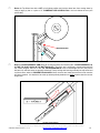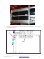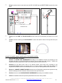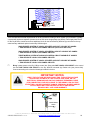
1
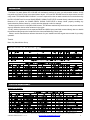
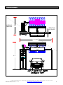
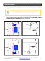
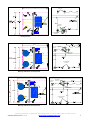
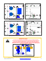
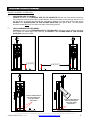
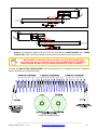
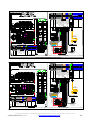
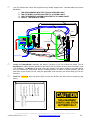
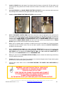
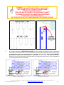
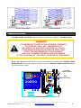
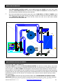
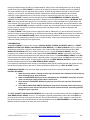
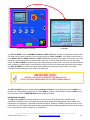
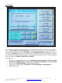
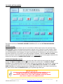
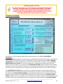
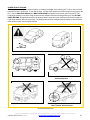
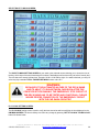
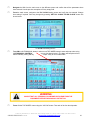
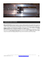
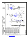
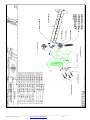
SINGLE AND THREE BRUSHES DRY-N-SHINE II INSTALLATION MANUAL TABLE OF CONTENTS Equipment Specifications Equipment Features Suggested Tools and Installation Materials Installation Instructions Electrical Installations Pneumatic Installations Plumbing Installations Operations and Startup Maintenance Page: 1 Page: 1 Page: 2 Page: 3 Page: 17 Page: 28 Page: 29 Page: 30 Page: 45 Equipment Requirements DRY N’SHINE II ONE 120 VAC 15 AMPS 1PH CIRCUIT + TOP WHEEL ONLY: ONE 208 VAC 20 AMPS 3PH CIRCUIT OR ONE 480 VAC 15 AMPS 3PH CIRCUIT TOP WHEEL AND SIDE WHEELS: ONE 208 VAC 40 AMPS 3PH CIRCUIT OR ONE 480 VAC 20 AMPS 3PH CIRCUIT + ONE 120VAC 15A CIRCUIT FOR SIGNS CONTROL: 1 OR 2 SIGNALS FROM CW CONTROLLER (24-240V AC-DC) + ONE SIGNAL FROM MASTER CONT RELAY (24-240V AC-DC) POWER: ELECTRICAL PNEUMATICS 3 SCFM WATER 10 GPM @ 40 PSI Notes and safety Symbols Where necessary, important points will be highlighted in this manual, using the following symbols: NOTE: PROVIDES FURTHER INFORMATION! STOP! PRECAUTION TO TAKE TO AVOID EQUIPMENT MALFUNCTION OR ERROR! WARNING! DANGEROUS SITUATION WHICH MAY CAUSE EQUIPMENT DAMAGE, PERSONAL INJURIES OR FATALITIES! Always follow all notes, warnings, and instructions. Failure to do so may have serious consequences on the overall performance of the equipment and/or the safety of the people working on the equipment! © Motor City Wash Works, Inc. 48285 Frank, Wixom Michigan 48393 U.S.A. Phone: 248.313.0272 ▪ Fax: 248. 313.0271 8MANULDNSINS002 07-23-14 www.motorcitywashworks.com 1 Introduction: The Motor City wash Works DRY N”SHINE will consistently produce dry cars, one after another another, all day long while using less HP than conventional blower dryers. Your new DRY N’SHINE has a few improvement over the early model: The SONAR READY SIGNAL” is no more required from the car wash controller but is now delivered by the DRY N”SHINE itself via a new SONAR READY SIGNAL PHOTO-EYE mounted directly under the sonar sensor. Because of it’s position, the SONAR READY SIGNAL PHOTO-EYE is always “timed” properly avoiding any synchronization problem cause by a vehicle who has skipped a roller for example. Another improvement is our simplified HMI screens: The different wash and dry functions are now pre-set and user are only allowed to choose a few variances in the cycles. Finally, another improvement is the separate RINSE and WASH spray manifolds mounted directly above or beside the wheels avoiding soap to be introduced in the rinse manifold during a rinse cycle. Please, use this manual has a reference document for your installers and also a great user manual for your daily operation. Thanks! Motor City Wash Works Group Utilities and Hardware Requirements: Electrical Requirements: SINGLE TOP WHEEL: © Motor City Wash Works, Inc. 48285 Frank, Wixom Michigan 48393 U.S.A. Phone: 248.313.0272 ▪ Fax: 248. 313.0271 8MANULDNSINS002 07-23-14 www.motorcitywashworks.com 2 THREE WHEELS SYSTEM: © Motor City Wash Works, Inc. 48285 Frank, Wixom Michigan 48393 U.S.A. Phone: 248.313.0272 ▪ Fax: 248. 313.0271 8MANULDNSINS002 07-23-14 www.motorcitywashworks.com 3 Physical Envelope: WORKING ENVELOPE 7' [2134] DIRECTION OF VEHICLE 13'-7" [4143] DRY N' SHINE S IGN 11’‐4” © Motor City Wash Works, Inc. 48285 Frank, Wixom Michigan 48393 U.S.A. Phone: 248.313.0272 ▪ Fax: 248. 313.0271 8MANULDNSINS002 07-23-14 www.motorcitywashworks.com 4 Installation Procedures Upon receiving your MCWW equipment, open all boxes and crates; verify that you have all the required components and that there is no damage to the equipment. Also verify that you have all your installation materials. PLEASE COMMUNICATE WITH YOUR LOCAL MOTOR CITY WASH WORKS REPRESENTATIVE FOR ANY DAMAGE TO YOUR EQUIPMENT! Remove packaging material covering your DRY-N-SHINE ™ TOP WHEEL and bring it to the wash in the area where it will be installed and verify that the area is sufficiently large for the DRY-N-SHINE ™ WHEELS WORKING ENVELOPE and DIMENSIONS (see picture #1 though #20). 9'-6" 7'-6" 6'-2" 8'-2" TOP WHEEL BASE PLTS 7'-6" 14'-3" DOORS CENTER LINE 2'-6" 6'-9" Pic #1: Working Envelope for Sngl. D/S Top Wheel Pic #2: Equipment Location for Sngl. D/S Top Wheel 9'-6" 7'-6" 5'-9" 7'-6" DOORS CENTER LINE 8'-6" 8'-2" 6'-2" TOP WHEEL BASE PLTS Pic #3: Working Envelope for Sngl. P/S Top Wheel Pic #4: Equipment Location for Sngl. P/S Top Wheel © Motor City Wash Works, Inc. 48285 Frank, Wixom Michigan 48393 U.S.A. Phone: 248.313.0272 ▪ Fax: 248. 313.0271 8MANULDNSINS002 07-23-14 www.motorcitywashworks.com 5 15' 6'-6" TOP WHEEL BASE PLTS D/S SUPERSHINER BASE PLTS 7'-6" 14'-3" DOORS CENTER LINE 6'-9" P/S SUPERSHINER BASE PLTS Pic #5: Working Envelope to Exit Wall for Sngl. D/S Top Wheel with Supershiner 17' Pic #6: Equipment Location TOP WHEEL BASE PLTS 8'-6" D/S SUPERSHINER BASE PLTS 7'-6" 14'-3" DOORS CENTER LINE P/S SUPERSHINER BASE PLTS 6'-9" Pic #7: Working Envelope to CV Trap Door for Sngl. D/S Top Wheel with Supershiner 7'-7" Pic #8: Equipment Location D/S SUPERSHINER BASE PLTS 6'-6" 8'-9" TOP WHEEL BASE PLTS P/S SUPERSHINER BASE PLTS Pic #9: Working Envelope to Exit Wall for Sngl. P/S Top Wheel with Supershiner 1" 1" Pic #10: Equipment Location © Motor City Wash Works, Inc. 48285 Frank, Wixom Michigan 48393 U.S.A. Phone: 248.313.0272 ▪ Fax: 248. 313.0271 8MANULDNSINS002 07-23-14 www.motorcitywashworks.com 6 17' D/S SUPERSHINER BASE PLTS 8'-6" 8'-9" TOP WHEEL BASE PLTS 1" P/S SUPERSHINER BASE PLTS Pic #11: Working Envelope to CV Trap Door for Sngl. P/S Top Wheel with Supershiner 1" Pic #12: Equipment Location 17' 6'-6" TOP WHEEL BASE PLTS D/S HIGH BOY BASE PLT 4'-1" 3'-3" 7'-6" DOORS CENTER LINE D/S SUPERSHINER BASE PLTS 14'-3" 7'-8" P/S SUPERSHINER BASE PLTS 6'-9" P/S HIGH BOY BASE PLT Pic #13: Working Envelope to Exit Wall for D/S Top Wheel With High Side Wheels and Supershiner Pic #14: Equipment Location 19' D/S HIGH BOY BASE PLT TOP WHEEL BASE PLTS 4'-1" 8'-6" 3'-3" 7'-6" D/S SUPERSHINER BASE PLTS 14'-3" 7'-8" P/S SUPERSHINER BASE PLTS 6'-9" 7'-7" P/S HIGH BOY Pic #15: Working Envelope to CV Trap Door for D/S Top Wheel With High Side Wheels and Supershiner Pic #16: Equipment Location © Motor City Wash Works, Inc. 48285 Frank, Wixom Michigan 48393 U.S.A. Phone: 248.313.0272 ▪ Fax: 248. 313.0271 8MANULDNSINS002 07-23-14 www.motorcitywashworks.com 7 D/S SUPERSHINER BASE PLTS D/S HIGH BOY BASE PLT 6'-6" 4'-1" 3'-3" 7'-8" 8'-9" TOP WHEEL BASE PLTS 1" P/S HIGH BOY BASE PLT P/S SUPERSHINER BASE PLTS Pic #17: Working Envelope to Exit wall for P/S Top Wheel With High Side Wheels and Supershiner 1" Pic #18: Equipment Location Pic #19: Working Envelope to CV Trap Door for P/S Top Wheel With High Side Wheels and Supershiner Pic #20: Equipment Location IMPORTANT NOTE: PAY PARTICULAR ATTENTION TO THE PROXIMITY OF THE LAST DRYER PRODUCERS: KEEP THE LAST DRYER PRODUCERS AS FAR AS POSSIBLE AND/OR POINTED AWAY FROM THE EXIT AND YOUR DRY N’SHINE WHEELS. THE AIR FLOW COMING FROM A DRYER PRODUCER LOCATED TOO CLOSE TO THE TOP WHEEL OR ANY OF THE SIDE WHEELS MAY INTERFERE WITH THE CLOTH AND REDUCE YOUR DRY N’SHINE EFFICIENCY AND/OR MAY BE THE CAUSE OF DAMAGES TO VEHICLES. 10' KEEP LAST TOP NOZZLE AT LEAST 10' AWAY FROM THE TOP WHEEL TO PREVENT AIR FLOW INTERFERENCE WITH DRY N'SHINE CLOTH TILT SIDE NOZZLES TOWARD ENTRANCE TO PREVENT AIR FLOW INTERFERENCE WITH DRY N'SHINE CLOTH Pic #21: Dryer Interferences © Motor City Wash Works, Inc. 48285 Frank, Wixom Michigan 48393 U.S.A. Phone: 248.313.0272 ▪ Fax: 248. 313.0271 8MANULDNSINS002 07-23-14 www.motorcitywashworks.com 8 Installation Procedures (following): SINGLE TOP WHEEL SYSTEM ONLY: FOR DRIVER SIDE TOP WHEEL: Position the frame on the DRIVER’S SIDE OF THE CONVEYOR with the two arms pointing toward the exit. Locate the frame entrance side to proper distance from exit according to the conveyor trap door or to the wall shown on pictures one through four (see above). Position the inside edge of the inside leg 21 INCHES to the OUTSIDE EDGE OF THE OUTSIDE GUIDE RAIL (see picture #22). The base plates should be located about 30” from the inside edge of the inside guide rail. FOR PASSENGER SIDE TOP WHEEL: Position the frame on the PASSENGER SIDE OF THE WASH BAY with the two arms pointing toward the exit. Position the inside edge of the inside leg 112 INCHES to the OUTSIDE EDGE OF THE OUTSIDE GUIDE RAIL (see picture #23). 1'-9" [21"] 9'-4" [112"] Pic #22: D/S Distance to Outside Guide Rail Pic #23: P/S Distance to Outside Guide Rail USE METAL SHIMS UNDER THE BASE PLATES AND SECURE WITH 5/8X6” WEDGE ANCHOR BOLTS Pic #24: Level Frame (1) USE METAL SHIMS UNDER THE BASE PLATES AND SECURE WITH 5/8X6” WEDGE ANCHOR BOLTS Pic #25: Level Frame (2) © Motor City Wash Works, Inc. 48285 Frank, Wixom Michigan 48393 U.S.A. Phone: 248.313.0272 ▪ Fax: 248. 313.0271 8MANULDNSINS002 07-23-14 www.motorcitywashworks.com 9 Level the frame in both directions (see picture #24 and #25). Secure to the floor using 5/8” X 5” WEDGE ANCHOR BOLTS (one for each floor mount holes). Attach the belt to the arm (see picture #26) and secure the 3/8-16 fastener holding the belts mount with the provided Loctite®. If your Top Wheel is installed on passenger side, reposition the DRIVE ARM ADAPTOR PLATES toward the wash bay center line like shown on picture #27 below. Pic #26: Connect The Belt Pic #27: Passenger Side Adaptor Plates Assembly PASSENGER SIDE TOP WHEEL: MOUNT THE ADAPTOR PLATES JUSTIFIED TOWARD THE CENTER LINE AS SHOWN IN PIC #27 Locate the DRIVE UNIT ASSEMBLY and mount to the adaptor plates as shown in pictures #28 or 29. Position the drive unit so that the DRIVER SIDE EDGE OF THE BRUSH should be lined-up with the OUTSIDE EDGE OF THE CONVEYOR OUTSIDE GUIDE RAIL © Motor City Wash Works, Inc. 48285 Frank, Wixom Michigan 48393 U.S.A. Phone: 248.313.0272 ▪ Fax: 248. 313.0271 8MANULDNSINS002 07-23-14 www.motorcitywashworks.com 10 Pic #28: Driver Side Drive Shaft Assembly Mounting (shown w/o motor or hub) Pic #29: Passenger Side Drive Shaft Assembly Mounting (shown w/o motor or hub) Remove the compression plates at the end of the hub and slide two FOAM SPACERS and a LARGE PLASTIC DISC. Slide a cloth disc and follow with foam spacers like shown on the picture below. MAKE SURE TO ALTERNATE THE CLOTH DISC FLAP UP AND DOWN BETWEEN EACH DISC. FAILURE TO DO SO MAY CAUSE THE TOP WHEEL BRUSH TO WOBBLE WHEN RUNNING AND MAY LEAD TO PREMATURE WEAR OF YOUR TOP WHEEL Terminate with ONE OR TWO FOAM SPACER in order to get at least 2-1/2” of compression from the compression plates. Reinstall the two compression plates. Pic #30: Cloth Loading Instructions © Motor City Wash Works, Inc. 48285 Frank, Wixom Michigan 48393 U.S.A. Phone: 248.313.0272 ▪ Fax: 248. 313.0271 8MANULDNSINS002 07-23-14 www.motorcitywashworks.com 11 Raise the Top Wheel arm with a LIFT to its highest position and lock the wheel arm from coming down by using a large pry bar or a piece of 1” PLUMBING PIPE SCHEDULE 80 in the hole below the arm (see picture #31) INSERT BAR HERE Pic #31: Lock the Top Wheel With the COUNTERWEIGHT ARM sitting at its lowest position and secure 9 X 1” COUNTERWEIGHTS (5 IN THE TOP SLOT AND 4 IN THE BOTTOM SLOT). Test if the top is sufficiently counter-balanced from the counter weights. Add one or two 1/4" COUNTERWEIGHTS to the counterweight arm box (see picture #32 and 33) until both arms are properly balanced. Test by raising and lowering manually the top wheel and confirm that the wheel is PROPERLY BALANCED: Move the arms and make sure that the brush remains still at any position. It is desired to have the top wheel perfectly balanced or slightly heavier than the counter weight arm. Pic #32: Counterweights © Motor City Wash Works, Inc. 48285 Frank, Wixom Michigan 48393 U.S.A. Phone: 248.313.0272 ▪ Fax: 248. 313.0271 8MANULDNSINS002 07-23-14 www.motorcitywashworks.com 12 Pic #33: Counterweight Arm Locate the cross beam and secure to the top wheel frame (see picture #34). Mount the cross beam leg on the other end of the cross beam. SECURE CROSS BEAM SECURE LEG SONAR Pic #34 Mounts Cross Beam and Leg. © Motor City Wash Works, Inc. 48285 Frank, Wixom Michigan 48393 U.S.A. Phone: 248.313.0272 ▪ Fax: 248. 313.0271 8MANULDNSINS002 07-23-14 www.motorcitywashworks.com 13 Using the pictures below, locate and mount the DRY N’ SHINE sign and BEATER BAR mounts to the cross beam. S ECURE SP LASHGUARD O N BE ATER BAR S ECURE SIGNS MOUNT O N MOUNT DRY N' SHINE S ECURE BE ATER BAR MOUNT O N THE CRO SS BEAM S ECURE SIGNS MOUNT O N THE CRO SS BEAM 1 7-1/2" S ECURE THE SIGN MOUNT 17-1/2" FROM LE G WELDMENT 5 0-5 8 " S ECURE BEA TER BA R MOUNT 50-5/8" FROM LE G WELDMENT 91" S ECURE P/S SIGN MOUNT MOUNT 91" FROM LE G WELDMENT ENTRANCE VIEW Pic #35 Dimensions Pic #36 Assembly Finally mount the SIGN, the SPLASH GUARD and the sonar to the cross beam (see picture 34, 35 and 36) Locate the boxes containing the COLOR SKINZ™ covers and install on each of the legs and arms (see below). Pic #36 Color` Skinz SINGLE TOP WHEEL (SINGLE WHEEL) WITH TIRE SHINER SYSTEM: FOR DRIVER SIDE TOP WHEEL: Position the DRIVER SIDE SUPERSHINER according to its installation manual and according to the conveyor trap door or to the wall shown on pictures five thru twelve (see early section). Position the Supershiner brushes assemblies on top of the conveyor guide rail (see Picture #37). Positions the top wheel frame close to its desired position (see Picture #37) according to the recommended distances shown on pictures 5 thru 12. Cut the conveyor outside guide rail following the Supershiner installation manual recommendations. Secure and level the Supershiner with anchor bolts. Remove the SQUARE CONNECTING BAR between the two Supershiner base plate and position the top wheel according to previous instruction. Secure and level the top wheel frame. Position and secure the PASSENGER SIDE SUPERSHINER according to its installation manual. Follow the installation instruction previously described for the rest of the top wheel. © Motor City Wash Works, Inc. 48285 Frank, Wixom Michigan 48393 U.S.A. Phone: 248.313.0272 ▪ Fax: 248. 313.0271 8MANULDNSINS002 07-23-14 www.motorcitywashworks.com 14 SQUARE CONNECTING BAR POSITIONED TOP WHEEL CLOSE TO SUPERSHINER POSITIONED ON TOP OF GUIDE RAIL Pic #37 Position the Supershiner FOR PASSENGER SIDE TOP WHEEL: Position the PASSENGER’S SIDE SUPERSHINER according to its installation manual and according to the conveyor trap door or to the wall shown earlier in this manual. Secure and level the Supershiner. Remove the SQUARE CONNECTING BAR between the two Supershiner base plate and position the top wheel according to previous instruction. Secure and level the top wheel frame. Position the DRIVER’S SIDE SUPERSHINER according to its installation manual. Position the Supershiner brushes assemblies on top of the conveyor guide rail and then cut the conveyor outside guide rail following the Supershiner installation manual recommendations. Secure and level the Supershiner with anchor bolts. TOP AND SIDE WHEELS SYSTEM (THREE WHEELS): Identify which of the layout resembles the most to your installation shown on pictures #13 thru 20. Use instructions previously described for the top wheel and Supershiner (if applicable) and locate the side wheels (High Boys) according to previous instructions. Secure and level the High Boys with 5/8” X 6” wedge anchor bolts to the floor. Locate the driver side BEATER BAR and mount to the driver side High-Boy (see Picture #38). Locate the SPLASH GUARD and mount to the beater bar. Repeat the same procedure for the passenger side. Finally, secure the hub to the wheel shaft: loosen the fasteners of the large boss clamp and slide on the brush shaft> Tighten the fasteners back evenly. © Motor City Wash Works, Inc. 48285 Frank, Wixom Michigan 48393 U.S.A. Phone: 248.313.0272 ▪ Fax: 248. 313.0271 8MANULDNSINS002 07-23-14 www.motorcitywashworks.com 15 SPLASH GUARD TOP VIEW BEATER BAR ELEVATION VIEW Pic #38 High Boys with Beater Bar and Splash Guard SLIDE HUB ONTO BRUSH SHAFT Pic #39 High Boys Hub © Motor City Wash Works, Inc. 48285 Frank, Wixom Michigan 48393 U.S.A. Phone: 248.313.0272 ▪ Fax: 248. 313.0271 8MANULDNSINS002 07-23-14 www.motorcitywashworks.com 16 Verify that the WHITE PLASTIC SPACERS are already secured in each hub channel (see picture #38) Start loading the bottom hub (or the bottom part of the hub) with FOUR FOAM SPACERS following by one 18” BLACK DISC. Slide ONE CLOTH DISC and then another FOUR FOAM SPACERS. Alternate between CLOTH DISC and FOAM following the instruction shown on picture #40 until 16 CLOTH DISCS ARE INSTALLED. MAKE SURE TO ALTERNATE THE CLOTH DISC FLAP UP AND DOWN BETWEEN EACH DISC. FAILURE TO DO SO MAY CAUSE THE SIDE WHEEL TO WOBBLE WHEN RUNNING AND MAY LEAD TO PREMATURE WEAR OF YOUR TOP WHEEL FOAMSPACER0001 72” LONG WHITE PLASTIC SPACERS QTY: 4 S RS CAPPLS01 OREENDCAP07007 LTHEX0036 CLOTH DISC 8DSO5O9O20GRY6 FLAP TO THE RIGHT CLOTH DISC CLOTH DISC 8DSO5O9O20GRY6 FLAP TO THE LEFT 18” BLACK PLSTC DISC SPACER 24” DIA Pic #40 High Boys Cloth Loading If desired, the wheel can be TILTED TOWARD THE VEHICLE for a better coverage of the vehicle side window area. To tilt the wheel against the vehicle, loosen the bolts holding the head assembly (see picture #40 and 41) and tilt the head toward the entrance of the wash. Tighten the bolts. LOOSEN BOLTS LOOSEN BOLTS Pic #41: Loosen Front Head Bolt Pic #42: Loosen Back Head bolts © Motor City Wash Works, Inc. 48285 Frank, Wixom Michigan 48393 U.S.A. Phone: 248.313.0272 ▪ Fax: 248. 313.0271 8MANULDNSINS002 07-23-14 www.motorcitywashworks.com 17 TILT 5° MAX Pic #43: 5 Degree Tilt Electrical Installation : There are different electrical requirements for the Dry N’Shine according to which system you purchased. Typically, a system will requires a separate 3 phase circuit as well as two single phase (see below): One single phase circuit for the Dry N’Shine control box and one additional circuit for the horizontal Dry N’Shine sign mounted on the top wheel and any additional optional vertical Dry N’Shine signs. SINGLE WHEEL SYSTEM AT 208VAC-2PH NEED A CIRCUIT CAPABLE OF 20AMPS + TWO SEPARATE 120VAC-1PH-15AMPS CIRCUITS (see Picture #43 below) SINGLE WHEEL SYSTEM AT 480VAC-3PH NEEDS A CIRCUIT CAPABLE OF 15AMPS + TWO SEPARATE 120VAC-1PH-15AMPS CIRCUITS THREE WHEELS SYSTEM AT 208VAC-2PH NEED A CIRCUIT CAPABLE OF 40AMPS + TWO SEPARATE 120VAC-1PH-15AMPS CIRCUITS SINGLE WHEEL SYSTEM AT 480VAC-3PH NEED A CIRCUIT CAPABLE OF 20AMPS + TWO SEPARATE 120VAC-1PH-15AMPS CIRCUITS Bring 3 phase power to the Dry N’Shine control box. Bring also ONE 120VAC-1PH CIRCUIT to the control box and ONE 120VAC-1PH CIRCUIT to the Dry N’Shine horizontal sign flasher unit (see picture #44). Connect according to the electrical drawings included in the box. IMPORTANT NOTES: VERIFY THE VOLTAGE BEFORE CONNECTING. THE SYSTEM VOLTAGE APPEARS ON THE BACK OF THE CONTROL BOX DOOR, ON THE ELECTRICAL DRAWINGS AND ON EACH VARIABLE FREQUENCY DRIVE (VFD) CONNECTING YOUR DRY N’SHINE TO THE WRONG 3 PH VOLTAGE SOURCE WILL CAUSE EQUIPMENT DAMAGE, PERSONAL INJURIES AND/OR FATALITIES!DO NOT PUNCH HOLES ON TOP OF ENCLOSURE. DOING SO WILL VOID YOUR WARRANTY 120VAC‐15AMPS CIRCUIT Pic #44 Flasher Unit © Motor City Wash Works, Inc. 48285 Frank, Wixom Michigan 48393 U.S.A. Phone: 248.313.0272 ▪ Fax: 248. 313.0271 8MANULDNSINS002 07-23-14 www.motorcitywashworks.com 18 X00 Y01 120V 1 2 3 4 5 6 7 8 9 1011 1213141516 24VDC 0VDC +24 0V NTRL 24VDC 0VDC SHIELD 24VDC 0VDC 120VAC-2A NEUTRAL C/W E-STOP IN DRY N-SHINE E-STOP DRY N-SHINE E-STOP C/W E-STOP OUT BEEFER 120VAC WHITE BLACK 2 0A D BLUE 2 0A D BROWN 2AD GREY 4AD COUNTER BALANCE TOP WHL DOWN TOP WHL RINSE TOP WHL SOAP SONR READY P/E TRCK DTECT LIGHT HOOD SNSR OUTPUT TOP WHL READY IN -/ TOP WHL READY IN+/ E STOP OK IN -/ E-STOP OK IN+/ 1 2 3 4 5 6 7 8 9 10111213 1415 16 11.750 208VAC P OWER ss R UN R UN D C OK +V ADJ 2AD 2AD 2AD E LC2-P C 12NNDR S TOP + P OWER ss X0 X0 X1 X1 X1 6 3 X2 X2 X2 NC NC X3 X3 X3 X4 X4 X4 X5 X5 X5 X6 X6 X6 X7 X7 X7 C0 C0 C0 Y0 C1 Y1 C2 Y2 Y3 Y0 Y1 Y2 Y3 Y4 L Y5 Y6 5 4 NO NO 11 14 Y1 A1 1 21 4 A1 1 2 14 A1 A2 11 A2 SUPPLIED SONAR SENSOR W/70' CABLE 12 1 4 Y2 A2 11 E LKO Y5 E LKO 11 E LKO Y6 7 Y7 R S-232 R S-485 8 A1 1 A2 A1 A2 A1 A2 12.750 2 20 VA Y3 Y4 C OM 0 12 Y0 Y7 N 14 12 11 14 12 11 14 12 11 L .V X0 E LC-E X 16NNDR B AT L . OW +V +V +V +V D C OK ss L .V E RR OR E LC-E X 16NNDR P OWER 2 C OM 1 A2 A1 A1 A2 11.750 WHEEL D OWN C OUN TER B ALANCE S ONAR READY SUPPLIED SONAR H OOD S ENSOR TRUCK D ETECT E-STOP BUTTON WASH BAY X00 Y01 120V 1 2 3 4 5 6 7 8 9 10 11 1213 14 1516 24VDC 0VDC CAR WASH CONTROLLER +24 0V N TRL 24VDC 0VDC SH IELD 24VDC 0VDC C /W E-STOP IN D RY N -SHINE E-STOP D RY N -SHINE E-STOP C /W E-STOP OUT BEEF ER 120VAC C OU NT ER BALANCE T OP WHL D OWN T OP WH L RINSE T OP WH L SOAP SON AR R EADY P/E T RC K DT EC T LIGHT H OOD SN SR OUTPUT T OP WH L R EADY IN -/ T OP WH L R EADY IN+/ E ST OP OK IN -/ E-ST OP OK IN+/ N EUT RAL 120VAC-2A 1 2 3 4 5 6 7 8 9 10 11 12 1314 15 16 NOTE: SIGNALS ARE NOT VOLTAGE SENSITIVE 24-240V AC/ DC WASH BAYE-STOP BUTTON SUPPLIED DRY N'SHINE E-STOP/BEEFER BUTTON STATION W/70' CABLE FIELD CONNECTIONS X00 Y01 Pic #45: 208VAC SNGL WHL Control Panel 120V 1 2 3 4 5 6 7 8 9 1011 1213 141516 24VDC 0VDC +24 0V NTRL 0VDC SHIELD 24VDC 0VDC 24VDC 120VAC-2A NEUTRAL C/W E-STOP IN DRY N-SHINE E-STOP DRY N-SHINE E-STOP C/W E-STOP OUT BEEFER 120VAC WHITE 1 5A D BLACK 1 5A D BLUE 1 5A D BROWN 2AD GREY 2AD COUNTER BALANCE TOP WHL DOWN TOP WHL RINSE TOP WHL SOAP SONR READY LIGHT TRCK DTECT LIGHT HOOD SNSR OUTPUT TOP WHL READY IN -/ TOP WHL READY IN+/ E STOP OK IN -/ E-STOP OK IN+/ 1 2 3 4 5 6 7 8 9 1011 12131415 16 11.750 460VAC P OWER ss R UN B AT L . OW 2AD 2AD 2AD 12 X1 6 3 X2 NC NC X3 X4 X4 X5 X5 X6 X6 X7 X7 C0 C0 Y0 C1 Y1 C2 Y2 Y3 Y0 Y1 Y2 Y3 Y4 Y5 Y6 X3 X4 X5 5 4 NO NO 11 14 X6 X7 SUPPLIED SONAR SENSOR W/70' CABLE C0 Y0 Y1 Y2 A1 12 1 4 A2 11 A1 12 14 A2 11 A1 1 21 4 A2 11 2 20 VA Y3 Y4 Y5 E LKO E LKO 7 Y7 0 C OM 8 A1 1 A2 A1 A2 12.750 E LKO Y6 Y7 L 14 12 11 14 12 11 14 12 11 X0 X2 R S-232 R S-485 N E LC2-P C12NNDR S TOP ss L .V X1 X2 E LC-E X 16NNDR R UN + P OWER X0 X1 X3 D C OK D C OK +V ADJ ss L .V X0 E RR OR +V +V +V +V E LC-E X 16NNDR P OWER A1 A2 A1 11.750 2 C OM 1 A2 A1 A2 WHEEL D OWN COUN TER B ALANCE S ONAR READY SUPPLIED SONAR H OOD S ENSOR TRUCK D ETECT 24VDC 0VDC CAR WASH CONTROLLER + 24 0V 120V 1 2 3 4 5 6 7 8 9 10 11 12 13 14 1516 X00 Y01 E-STOP BUTTON WASH BAY N TRL 0VDC 24VDC SH IELD 24VDC 0VDC C /W E-STOP IN D RY N -SHINE E-STOP D RY N -SHINE E-STOP C /W E- STOP OUT BEEF ER 120VAC C OU NT ER BALANCE T OP WHL D OWN T OP WH L RINSE T OP WH L SOAP SON R READ Y LIGHT T RC K DT EC T LIGHT H OOD SN SR OUTPUT T OP WH L R EADY IN -/ T OP WH L R EADY IN+/ E ST OP OK IN -/ E-ST OP OK IN+/ N EUT RAL 120VAC-2A 1 2 3 4 5 6 7 8 9 10 11 1213 14 15 16 NOTE: SIGNALS ARE NOT VOLTAGE SENSITIVE 24-240V AC/ DC WASH BAYE-STOP BUTTON SUPPLIED DRY N'SHINE E-STOP/BEEFER BUTTON STATION W/70' CABLE FIELD CONNECTIONS Pic #46: 480VAC SNGL WHL Control Panel © Motor City Wash Works, Inc. 48285 Frank, Wixom Michigan 48393 U.S.A. Phone: 248.313.0272 ▪ Fax: 248. 313.0271 8MANULDNSINS002 07-23-14 www.motorcitywashworks.com 19 X00 Y01 120V 1 2 3 4 5 6 7 8 9 10 1112131415 16 17 1819 20 21 24VDC 0VDC +24 0V NTRL 2 0A D 20A D 20A D 20A D 11.750 P OWER ss R UN 208VAC P OWER L .V X0 X1 B AT L . OW D C OK 14 12 11 14 12 11 14 12 11 14 12 11 X2 X3 X4 X5 6 3 NC NC 11 X3 X4 X5 X6 X6 X6 X7 X7 X7 C0 C0 5 4 NO NO 14 SUPPLIED SONAR SENSOR W/70' CABLE 2AD 2A D C1 Y1 C2 Y2 Y3 Y0 Y1 Y2 Y3 Y4 Y5 Y6 Y0 Y1 A1 1 21 4 A1 12 1 4 A2 11 A1 12 14 A2 11 A1 1 2 14 A2 11 2 20 VA Y2 Y3 A2 Y4 11 E LKO Y5 E LKO E LKO 7 Y7 0 R S-485 C OM A1 A2 A1 A2 A1 A2 2 C OM 8 A2 1 A2 12.750 E LKO Y6 Y7 L R S-232 N 2AD Y0 C0 E LC-E X 16NNDR +V ADJ E LC-E X 16NNDR E LC2-P C12NNDR S TOP + 1 A1 A1 A1 A2 WHEEL DOWN 11.750 REMOVE SHUNT INTERNAL BRIDGE Y01 X00 0VDC +24 0V 0VDC 24VDC SH IELD 24VDC 0VDC C /W E- STOP IN D RY N -SHINE E-STOP D RY N -SHINE E-STOP C /W E- STOP OUT BEEFER 120VAC C OU NTER BALANCE TOP WHL D OWN TOP WH L RINSE T OP WH L SOAP SON R R EADY P/E TRC K DTEC T LIGHT T OP WHL H OOD SN SR SID E WH EELEXTEND SID E WH EELRINSE SID E WH EELSOAP T OP WH L READY IN T OP WH L READY IN SID E WH L READY IN SID E WH L READY IN E ST OP OK IN E- ST OP OK IN CAR WASH CONTROLLER NOTE: SIGNALS ARE NOT VOLTAGE SENSITIVE 24-240V AC/ DC N EUTRAL SUPPLIED SONAR H OOD S ENSOR TRUCK DETECT E-STOP BUTTON WASH BAY 24VDC 1 2 3 4 5 6 7 8 9 10 11 12 1314 15 16 17 1819 20 21 120VAC-2A COUNTER B ALANCE S ONAR READY 120V 1 2 3 4 5 6 7 8 9 10 11 1213 14 15 16 17 1819 20 21 N TRL 0VDC 24VDC SHIELD 24VDC 0VDC 12 X1 X2 X4 X5 208VAC X0 X1 X2 X3 R UN ss L .V X0 E RR OR + V +V +V +V D C OK P OWER ss WHITE 4 0A D BLACK 40A D BLUE 40A D BROWN 2A D GREY 4AD COUNTER BALANCE TOP WHL DOWN TOP WHL RINSE TOP WHL SOAP SONR READY P/E TRCK DTECT LIGHT TOP WHL HOOD SNSR SIDE WHEEL EXTEND SIDE WHEEL RINSE SIDE WHEEL SOAP TOP WHL READY IN TOP WHL READY IN SIDE WHL READY IN SIDE WHL READY IN E STOP OK IN E-STOP OK IN C/W E-STOP IN DRY N-SHINE E-STOP DRY N-SHINE E-STOP C/W E-STOP OUT BEEFER 120VAC NEUTRAL 120VAC-2A 1 2 3 4 5 6 7 8 9 10 11 12 13141516 17 18 19 20 21 WASH BAYE-STOP BUTTON SUPPLIED DRY N'SHINE E-STOP/BEEFER BUTTON STATION W/70' CABLE FIELD CONNECTIONS 120V 1 2 3 4 5 6 7 8 9 10 1112131415 16 1718 19 20 21 24VDC 0VDC +24 0V NTRL X00 Y01 Pic #47: 208VAC THREE WHLS Control Panel 1 5A D 1 5A D 1 5A D 1 5A D 1 5A D 1 5A D 11.750 P OWER ss R UN E RR OR B AT L . OW +V +V +V +V D C OK R UN D C OK P OWER 460VAC ss L .V P OWER ss X0 X1 X1 6 X2 X2 NC X3 X3 X3 X4 X4 X4 5 X5 X5 X5 NO X6 X6 X6 X7 X7 X7 C0 C0 C0 3 NC 4 NO 11 C2 Y2 Y3 Y3 Y4 Y5 Y6 E LC-E X 16NNDR 2AD Y1 Y2 14 SUPPLIED SONAR SENSOR W/70' CABLE Y7 L Y0 Y1 A1 1214 A1 12 14 A1 1214 A1 12 14 A2 11 A2 11 A2 11 A2 11 2 20 VA Y2 Y3 Y4 Y5 E LKO E LKO E LKO E LKO Y6 7 Y7 0 C OM R S-232 R S-485 N 2AD C1 Y1 E LC-E X 16NNDR 2A D E LC2-P C12NNDR +V ADJ 1 A2 A1 A2 A1 A2 A1 A2 2 C OM 8 1 A1 A2 A1 A1 A2 WHEEL D OWN 11.750 REMOVE SHUNT INTERNAL BRIDGE X00 Y01 0VDC 0VDC 0VDC 24VDC SH IELD 24VDC 0VDC C OU NT ER BALANCE T OP WHL D OWN T OP WH L RINSE T OP WH L SOAP SON R R EADY P/E T RC K DT EC T LIGHT T OP WHL H OOD SN SR SID E WH EELEXTEND SID E WH EELRINSE SID E WH EELSOAP T OP WH L READY IN T OP WH L READY IN SID E WH L READY IN SID E WH L READY IN E ST OP OK IN E-ST OP OK IN C /W E-STOP IN D RY N -SHINE E-STOP D RY N -SHINE E-STOP C /W E-STOP OUT BEEF ER 120VAC N EUT RAL 1 2 3 4 5 6 7 8 9 10 11 1213 14 15 16 17 18 19 20 21 120VAC-2A SUPPLIED SONAR H OOD S ENSOR TRUCK DETECT E-STOP BUTTON WASH BAY 24VDC +24 0V 120V 1 2 3 4 5 6 7 8 9 10 11 121314 15 16 1718 19 20 21 C OUN TER B ALANCE S ONAR READY NOTE: SIGNALS ARE NOT VOLTAGE SENSITIVE 24-240V AC/ DC N TRL 0VDC 12 X0 X2 Y0 24VDC 14 12 11 14 12 11 14 12 11 14 12 11 L .V X0 X1 Y0 SHIELD 24VDC 0VDC 460VAC S TOP + WHITE 2 0A D BLACK 2 0A D BLUE 2 0A D BROWN 2AD GREY 4AD COUNTER BALANCE TOP WHL DOWN TOP WHL RINSE TOP WHL SOAP SONR READY P/E TRCK DTECT LIGHT TOP WHL HOOD SNSR SIDE WHEEL EXTEND SIDE WHEEL RINSE SIDE WHEEL SOAP TOP WHL READY IN TOP WHL READY IN SIDE WHL READY IN SIDE WHL READY IN E STOP OK IN E-STOP OK IN C/W E-STOP IN DRY N-SHINE E-STOP DRY N-SHINE E-STOP C/W E-STOP OUT BEEFER 120VAC NEUTRAL 120VAC-2A 1 2 3 4 5 6 7 8 9 10 11 12 13141516 17 18 19 20 21 CAR WASH CONTROLLER WASH BAYE-STOP BUTTON SUPPLIED DRY N'SHINE E-STOP/BEEFER BUTTON STATION W/70' CABLE FIELD CONNECTIONS Pic #48: 480VAC THREE WHEELS Control Panel © Motor City Wash Works, Inc. 48285 Frank, Wixom Michigan 48393 U.S.A. Phone: 248.313.0272 ▪ Fax: 248. 313.0271 8MANULDNSINS002 07-23-14 www.motorcitywashworks.com 20 Your Dry N’Shine also requires a few CONTROL SIGNALS from your car wash controller: ONE TOP WHEEL READY SIGNAL: This signal will bring the top wheel down. The signal has to be program to bring the top wheel down soon enough in order to meet ahead of the vehicle. The signal can be any voltage between 24 to 240 VOLTS AC or DC. ONE SIDE WHEEL READY SIGNAL (FOR THREE WHEELS SYSTEM ONLY!): This signal will bring the side wheels in. The signal has to be program to bring the side wheels in soon enough in order to meet ahead of the vehicle. The signal can be any voltage between 24 to 240 VOLTS AC or DC. IMPORTANT NOTE: THE SONAR READY SIGNAL HAS BEEN REPLACED BY A PHOTOEYE WHERE THE EMITTER IS MOUNTED ON THE CROSSBEAM LEG CLOS TO THE FLOOR AND THE RECEIVER ON THE TOP WHEEL FRAME BESIDE THE TOP WHEEL 3 POSITIONS CYLINDER BASE. IT IS SHIPPED UNMOUNTED. MOUNT THE PHOTO-EYE ASSEMBLY WITH THE RECEIVER POINTING TOWARD THE EMIITER TO THE FLOOR. IT IS AN IMPORTANT COMPONENT OF YOUR DRY N’SHINE SYSTEM. MANY SAFETY FEATURES BUILT IN YOUR DRY N’SHINE SYSTEM DEPENDS ON THE SONAR READY SIGNAL AND ITS ACCURACY. INSURE THAT BOTH HOOD SENSOR AND SONAR READY PHOTOEYES ARE NOT “CROSS TALKING”. ONE E-STOP OK SIGNAL (FOR SAFETY PURPOSE): This signal will enable the Dry N’Shine and its components to RUN IF ANY OF THE WASH E-STOP IS NOT PUSHED. The signal has to be always ON and then turns OFF if any of all the wash emergency stop button is pushed. The signal can be any voltage between 24 to 240 VOLTS AC or DC. VERY IMPORTANT SAFETY ISSUE: AN EMERGENCY STOP BUTTON IS PART OF A SYSTEM INTENDED FOR USE IN EMERGENCY CONDITIONS TO TRY TO LIMIT OR AVERT HARM TO SOMEONE OR SOMETHING BECAUSE OF THE AUTOMATIC NATURE OF THE DRY N’SHINE START AND STOP. THE E-STOP OK SIGNAL BECOMES A CRITICAL PART OF YOUR WORKERS AND/OR PUBLIC PROTECTIVE MEASURES. UNDERSTAND AND INTERCONNECT THE CAR WASH EMERGENCY STOP CIRCUIT WITH YOUR DRY N’SHINE CONTROLLER SHOULD BE RECOGNIZED HAS A PRIORITY FOR YOUR INSTALLER AND/OR ELECTRICAL CONTRACTOR. Pull wires from your car wash controller to the Dry N’Shine control box: 6 WIRES for a Single Wheel system (top wheel only) and 8 WIRES for a three wheels system (top wheel and side wheels). These wires will be used for the different READY signals and the E-STOP OK signal. IMPORTANT NOTE: DO NOT PUNCH HOLES ON TOP OF ENCLOSURE. DOING SO WILL VOID YOUR WARRANTY © Motor City Wash Works, Inc. 48285 Frank, Wixom Michigan 48393 U.S.A. Phone: 248.313.0272 ▪ Fax: 248. 313.0271 8MANULDNSINS002 07-23-14 www.motorcitywashworks.com 21 Your Dry N’Shine also comes with equipment many already supplied with extended cables (see picture #49 below): 1234- THE SONAR SENSOR W/50 FEET OF 4C/20 SHIELDED CABLE THE TOP WHEEL CONTROL W/50 FEET OF 7C/18AWG CABLE THE E-STOP/BEEPER ASSEMBLY W/50 FEET OF 5C/18AWG CABLE FINALLY, THE SIGN W/10’ CABLE 2C/14AWG FIELD SUPPLIED FIELD SUPPLIED WA S H R E W O P R GE N E S S ON AR P OWER S ID E WH EELS R EADY R EADY T OP WHEEL R EADY WA R N ING! WAS H CY CLE C C 0 SIGN T W OR S K I TY S ID E WH EELS SONAR Y ME TOP WHEEL R M FIELD SUPPLIED TOP WHEEL AIR F AULT! P T OP WHE EL#2 R EADY 1 0 K R N P L A C D 8 E-STOP/BEEFER MOTO R CITY DRY N' SHINE FIELD SUPPLIED MOTOR CABLE POWER WHE EL P EN ET RA TION SHIELDED CABLE M AI N AIR S UPPLY S T A RT U P - 4 PAIR CABLE A D J U S T ME S T N M AI NA IR 4 0 P I S P EN ET RAT N IO 2 0 A cel er ator P I S M T z ri e h w lp ta n o 1 0 N W P T L A C D 8 WATER SUPPLY SHIELDED CABLE CO UN T E R BL E C N A Pic #49 Electrical and misc. Utility for Single Top Wheel C C TOP WHEEL READY BOX 7C/18 CONTROL CORD SIDE WHEELS CHEM A TOP AND SIDE WHEEL MOTORS C CW CONTROLLER SIGNALS AND CW E-STOP TOP WHEEL H20 SIDE WHEELS H20 B A DRY N'SHINE SONAR Install the “CAUTION” sign (see picture #51) near the Dry N’Shine top wheel and its emergency stop button. DRY N'SHINE BEEFER TOP WHEEL CHEM Locate the E-Stop/Beeper assembly and install in proximity of the Dry N’Shine top wheel. The EStop/Beeper is used to stop the operation of the wash or the Dry N’Shine at any moment if needed in case of an emergency. The Beeper will be used to warn the operator or any person located in the vicinity before your Dry N’Shine start a scheduled drying or washing operation or before a manual operation. Pull the cable back to the control box and, using the appropriate cord connector (see Picture #48), pull into the enclosure. SIDE WHEELS EXTEND D D Pic #50 Control Box Knock-Out Holes and Connectors Pic #51: Caution Sign © Motor City Wash Works, Inc. 48285 Frank, Wixom Michigan 48393 U.S.A. Phone: 248.313.0272 ▪ Fax: 248. 313.0271 8MANULDNSINS002 07-23-14 www.motorcitywashworks.com 22 Install the SONAR under main beam (if not already done) like shown on picture #34. Pull the cable to the control box and using the Micro DC female connector mounted on the bottom of the control box, connect the sonar. Pull HOOD SENSOR and SONAR READY EMITTER PHOTO-EYE thru the cross beam and mount onto the passenger side: Hood sensor the highest and Sonar ready the lowest. Install the SONAR READY EMITTER PHOTO-EYE like shown below: Pic #50A Sonar Photo-Eye when Received Pic #50B: Sonar Photo-Eye Installed Pull the TOP WHEEL CONTROL BOX cable to the control box using the appropriate cord connector (see Picture #48), pull into the enclosure. The control box mounted on your top wheel is used as a junction box for three air valves (TOP WHEEL DOWN, COUNTER BALANCE and THREE POSITIONS) as well as two indicator lights: SONAR READY and TRUCK DETECT light. The SONAR READY light will be used to synchronized the SONAR READY SIGNAL with the front of the vehicle being washed while the TRUCK DETECT light will confirm when an open bed have been detected. Pull a new Low Voltage cable 2 Conductors 14 AWG from the sign to the flasher unit. Connect the flasher unit power cord into a 120VAC outlet. From the car wash controller, connect one OUTPUT FUNCTION to the flasher unit control input. Pull a 4 CONDUCTOR #14 AWG cable (300 or 600 VOLT RESISTANT) from the top wheel motor to the control box and using one of the knock-out holes available. If your system includes a set of HIGH-BOYS SIDE WHEELS pull an additional 4 CONDUCTOR #14 AWG cable (300 or 600 VOLT RESISTANT) for each motor, one for DRIVER SIDE and one for PASSENGER SIDE. Pull a pair of wire from the CAR WASH E-STOP STRING (chose the closest car wash e-stop junction box) to the Dry N’Shine control box. Connect all the wire in the control box according to the electrical diagram below: Single wheel system (picture #52) or three wheels system (picture #53). Connect each motor cable to the 1.5 HP DRIVE MOTORS: TOP WHEEL AND SIDE WHEELS (if applicable). NOTES: EACH MOTOR ELECTRICAL CABLES ARE NOT CONNECTED TO THE MOTOR LEADS WHEN SHIPPED FROM THE FACTORY. OPEN THE MOTOR CONNECTION BOXES AND CONNECT TO THE MOTOR LEADS FOLLOWING THE APPROPRIATE CONNECTION DIAGRAM BELOW OR ON THE MOTOR PLATE (PICTURES #54) AND FOR PROPER VOLTAGE. © Motor City Wash Works, Inc. 48285 Frank, Wixom Michigan 48393 U.S.A. Phone: 248.313.0272 ▪ Fax: 248. 313.0271 8MANULDNSINS002 07-23-14 www.motorcitywashworks.com 23 X00 Y01 120V 1 2 3 4 5 6 7 8 9 1011 1213141516 24VDC 0VDC +24 0V NTRL 0VDC 24VDC SHIELD 24VDC 0VDC 120VAC-2A NEUTRAL C/W E-STOP IN DRY N-SHINE E-STOP DRY N-SHINE E-STOP C/W E-STOP OUT BEEFER 120VAC WHITE BLACK BLUE BROWN GREY COUNTER BALANCE TOP WHL DOWN TOP WHL RINSE TOP WHL SOAP SONR READY P/E TRCK DTECT LIGHT HOOD SNSR OUTPUT TOP WHL READY IN -/ TOP WHL READY IN+/ E STOP OK IN -/ E-STOP OK IN+/ 1 2 3 4 5 6 7 8 9 10111213 1415 16 SUPPLIED SONAR SENSOR W/70' CABLE WHEEL D OWN C OUN TER B ALANCE S ONAR READY SUPPLIED SONAR H OOD S ENSOR TRUCK D ETECT E-STOP BUTTON WASH BAY CAR WASH CONTROLLER NOTE: SIGNALS ARE NOT VOLTAGE SENSITIVE 24-240V AC/ DC WASH BAYE-STOP BUTTON SUPPLIED DRY N'SHINE E-STOP/BEEFER BUTTON STATION W/70' CABLE FIELD CONNECTIONS Pic #52 Control Box Connection Layout for Single Wheel System © Motor City Wash Works, Inc. 48285 Frank, Wixom Michigan 48393 U.S.A. Phone: 248.313.0272 ▪ Fax: 248. 313.0271 8MANULDNSINS002 07-23-14 www.motorcitywashworks.com 24 X00 Y01 120V 1 2 3 4 5 6 7 8 9 10 1112131415 16 17 1819 20 21 24VDC 0VDC +24 0V NTRL 0VDC 24VDC SHIELD 24VDC 0VDC WHITE BLACK BLUE BROWN GREY COUNTER BALANCE TOP WHL DOWN TOP WHL RINSE TOP WHL SOAP SONR READY P/E TRCK DTECT LIGHT TOP WHL HOOD SNSR SIDE WHEEL EXTEND SIDE WHEEL RINSE SIDE WHEEL SOAP TOP WHL READY IN TOP WHL READY IN SIDE WHL READY IN SIDE WHL READY IN E STOP OK IN E-STOP OK IN C/W E-STOP IN DRY N-SHINE E-STOP DRY N-SHINE E-STOP C/W E-STOP OUT BEEFER 120VAC NEUTRAL 120VAC-2A 1 2 3 4 5 6 7 8 9 10 11 12 1314 15 16 17 18 19 20 21 SUPPLIED SONAR SENSOR W/70' CABLE WHEEL D OWN COUN TER B ALANCE S ONAR READY SUPPLIED SONAR H OOD S ENSOR TRUCK D ETECT E-STOP BUTTON WASH BAY NOTE: SIGNALS ARE NOT VOLTAGE SENSITIVE 24-240V AC/ DC CAR WASH CONTROLLER WASH BAYE-STOP BUTTON SUPPLIED DRY N'SHINE E-STOP/BEEFER BUTTON STATION W/70' CABLE FIELD CONNECTIONS Pic #53 Control Box Connection Layout for Three Wheel System Connect each motor cable to the 1.5 HP DRIVE MOTORS: TOP WHEEL AND SIDE WHEELS (if applicable). © Motor City Wash Works, Inc. 48285 Frank, Wixom Michigan 48393 U.S.A. Phone: 248.313.0272 ▪ Fax: 248. 313.0271 8MANULDNSINS002 07-23-14 www.motorcitywashworks.com 25 NOTES: EACH MOTOR ELECTRICAL CABLES ARE NOT CONNECTED TO THE MOTOR LEADS WHEN SHIPPED FROM THE FACTORY. OPEN THE MOTOR CONNECTION BOXES AND CONNECT TO THE MOTOR LEADS FOLLOWING THE APPROPRIATE CONNECTION DIAGRAM BELOW OR ON THE MOTOR PLATE (PICTURES #54) AND FOR PROPER VOLTAGE. TOP WHEEL MOTOR MAIN CONNECTION BOX 1.5HP/208-460VAC 3PH Pic #54 Motor Connections Pic #55 Top Wheel Connection Box If you have purchase the THREE WHEEL SYSTEM, in order to access the electrical motors, loosen the top bolt located on the entrance side of the arm flange (see picture #56 below) and remove the three other bolts secured through the flange (see pictures# 57 and 58) and then TILT THE HEAD ASSEMBLY DOWNWARD TOWARD THE ENTRANCE OF THE WASH until the brush is laying flat on the floor. Remove the cover from the motor (see picture #59) and connect the cable into the motor. Reinstall the cover and reposition the head assembly. REMOVE REMOVE BOLT LOOSEN BOLT Pic #56: Loosen Head Bolt Pic #57: Remove Head bolt © Motor City Wash Works, Inc. 48285 Frank, Wixom Michigan 48393 U.S.A. Phone: 248.313.0272 ▪ Fax: 248. 313.0271 8MANULDNSINS002 07-23-14 www.motorcitywashworks.com 26 LOOSEN BOLTS TILT DOWN Pic #58: Loosen Head Bolt s Pic #59: Tilt Head Down Pneumatic Installation: Your DRY N’SHINE TOP WHEEL requires a supply of compressed air capable of 3 SCFM @ 100 PSI. WARNING! IT IS IMPERATIVE TO SUPPLY THE TOP WHEEL PNEUMATIC SYSTEM WITH CLEAN, DRY, COMPRESSED AIR. ANY AMOUNT OF MOISTURE, VAPORIZED OIL, OR ANY OTHER IMPURITIES WITHIN THE MAIN AIR SUPPLY MAY AFFECT THE PERFORMANCE OF THE EQUIPMENT AND LEAD TO PREMATURE WEAR OR MAJOR DAMAGE TO THE ACCELERATOR™ DELIVERY SYSTEM OR ITS COMPONENTS. Bring a 3/8” OD polyflow tubing air line from the main compressed air supply to the CONTROL PANEL MAIN AIR SUPPLY (see picture # 60) and another one from the CONTROL PANEL AIR REGULATOR to the top wheel main air panel. TOP WHEEL AIR SUPPLY HERE M T R 0 WAS H WO RKS C WA RNING! WA S H CYCLE ER M GEN S P OWER S ONAR REA DY S IDE WHEE LS REA DY T OP WHE EL REA DY C I T Y S IDE WHEELS Y E P OW E R P MAIN AIR SUPPLY HERE F AULT! T OP WHEEL #2 REA DY 8 DCA LPN LRK R0001 MOTOR CITY DRY N' SHINE Pic #60 Air Panel Location © Motor City Wash Works, Inc. 48285 Frank, Wixom Michigan 48393 U.S.A. Phone: 248.313.0272 ▪ Fax: 248. 313.0271 8MANULDNSINS002 07-23-14 www.motorcitywashworks.com 27 (2) 1/2” HOSE TO HIGH BOYS (2) 1/2” HOSE TO TOP WHEEL M T R 0 WAS H WO RKS WA RNING! WA S H CYCLE P O WE R ER M G EN E P OWER S ONAR REA DY S IDE WHEE LS REA DY CI T Y S ID E WH EELS Y S DNS CONTROL BOX C T OP WHE EL REA DY P HIGH BOYS (SIDE WHEELS) AIR PANEL F AULT! T OP WHEEL #2 REA DY 8 DCA LPN LRK R0001 MOTOR CITY DRY N' SHINE Pic #61 Control Panel Utilities FRESH WATER SUPPLY HERE If you have purchased the three wheel system, bring a 3/8” OD polyflow tubing air lines from the main compressed air supply to the HIGH BOYS (SIDE WHEELS) AIR PANEL AIR SUPPLY (see picture #61). Pull and connect ONE 3/8” RED AIRLINE TUBE from the EXTEND AIR VALVE located on the air Panel to cylinder back end of the P-S BRUSH. Pull and connect ONE 3/8” BLUE AIRLINE TUBE from the D-S EXTEND AIR REGULATOR located on the air Panel to the cylinder back end of the D-S BRUSH. Pull and connect ONE 3/8” BLACK AIRLINE TUBE from the 4 WAY SOLENOID AIR VALVE to the wash bay, BETWEEN THE TWO BRUSHES and tee off to EACH BRUSH rod end cylinders. Pic #61-A: Air Lines © Motor City Wash Works, Inc. 48285 Frank, Wixom Michigan 48393 U.S.A. Phone: 248.313.0272 ▪ Fax: 248. 313.0271 8MANULDNSINS002 07-23-14 www.motorcitywashworks.com 28 Water Feed Installation: Your DRY-N-SHINE CONTROL PANEL requires ONE (or two) 3/4” HOSES from fresh water supply feeding the DILUTION STATION (see Picture #61) and then TWO 1/2” HOSES from the dilution station to the top wheel water manifolds mounted on the beater bar. If you have purchased the three wheel system with a set of HIGH BOYS, pull TWO 1/2” HOSES to both Side Wheels by teeing the hoses above the first wheel. Connect the hoses to the second dilution station outlet IDENTIFIED HIGH BOYS (see Picture #61-B). Connect the other end to each water manifold mounted to the side wheels beater bar. K R O H S A W R E W O P WA R N I N ! G G WA S H CC E L Y SI DE WH S L E F A UL ! T SONR A P O WE R RE AD Y SI DE WH S L E READ Y TOP WE L H REA D Y T OP WH E L 2 # E REA D Y 1 0 K R N P L A C D 8 MOTOR CITY D RY N' SHINE Pic #61-B Water Lines Operation and Start Up Procedures: INTRODUCTION TO DRY N’SHINE 101: Your DRY ‘N SHINE™ is not the first FRICTION DRYING SYSTEM ever sold in the car wash industry, but we think it’s the first to live up to the promise of consistently producing dry cars, one after the other, all day long, while using less horse power. Your DRY ‘N SHINE™ was designed to overcome the two major obstacles of “old style” friction drying machines: The first obstacle for the old machines was dirt. Even though the drying machine was supposed to be wiping clean cars, the drying material quickly became contaminated with dirt over a few days time and eventually transferred the dirt back onto the vehicles. The old solution was to rotate two sets of material, requiring constant labor and attention. Your DRY ‘N SHINE™ beats the dirty drying material problem with a PROGRAMMABLE AUTOMATIC WASH AND RINSE CYCLE that cleans and rinses the drying material when the carwash is closed. This feature launders © Motor City Wash Works, Inc. 48285 Frank, Wixom Michigan 48393 U.S.A. Phone: 248.313.0272 ▪ Fax: 248. 313.0271 8MANULDNSINS002 07-23-14 www.motorcitywashworks.com 29 the drying material without any labor or constant attention. Simply set the self-cleaning wash cycle to run during closed hours and your DRY ‘N SHINE™ machine will be ready to go when your carwash opens in the Morning! The second problem was over saturated drying material. Old style drying material used was an artificial leather “shammy”, or a very thick, fast absorbing synthetic material which quickly became saturated and rendered ineffective. Those materials do not dry out quickly enough to continue drying more than a few cars in a row. Your DRY ‘N SHINE™ handles the over saturation issue with a PROGRAMMABLE AUTOMATIC SPIN DRY CYCLE that dramatically accelerates evaporation in between cars. This feature has the ability to INCREASE THE RPM of the drying wheels when they are not in contact with a vehicle, using centrifugal force to push water to the outer diameter of the drying wheel. Then the drying wheels RPM are increased again, forcing the material to make contact with a BEATER BAR, allowing the material to “extract” any accumulated water from the outer diameter of the drying wheels. The spin dry cycle allows the drying wheel to always remain in a state of absorption and therefore always effective. Your DRY ‘N SHINE™ offers great customer appeal and loads of added value. It’s able to effectively remove the last 20% of water droplets still remaining on vehicles directly following a 50 or 70HP forced air dryer at a continuous operating rate of 100 CARS PER HOUR without reaching the point of saturation. It’s the first mechanical drying machine that can consistently produce dry cars, one after the other, all day long, while quietly using less horse power and offering exciting revenue opportunities. FUNDAMENTALS: Your DRY ‘N SHINE™ comes in two versions: A SINGLE WHEEL SYSTEM (TOP WHEEL ONLY) or a THREE WHEELS SYSTEM (TOP WHEEL AND HIGH BOYS SIDE WHEELS). Two INPUT SIGNALS from your car wash controller are required for a single top wheel system: One to start the top wheel to come down and spin (TOP WHEEL READY SIGNAL) and one to enable the system to run or to stop (E-STOP OK SIGNAL) during an emergency stop condition in the wash. A third signal called SONAR READY SIGNAL is also sent to the Control panel via a set of photo-eyes located in-line and under the sonar sensor. The SONAR READY SIGNAL will be ON when the front of the vehicle reaches under the physical position of the sonar sensor and OFF when the rear of the vehicle reaches the sonar position. A fourth signal is required for a THREE WHEELS SYSTEM: a signal to extend the side wheels and spin the brushes (SIDE WHEELS READY SIGNAL). It is important to understand that the accuracy of the different ready signals synchronized with the vehicle receiving the service will greatly influence the level of quality and efficiency delivered by your DRY ‘N SHINE™ system. SONAR READY SIGNAL: The new sonar ready signal photo-eyes are the most important feature of the DRY N’SHINE TOP WHEEL. 1. Starts the sensor which is looking for truck open bed which when detected will retract the top wheel avoiding it to go down in the bed. 2. Starts a COUNTERBALANCE air pressure that lightens the TOP WHEEL during the very front of the car and stops it beyond the vehicle’s wipers area. 3. Slows down the TOP WHEEL RPM during the very front of the car and stops it beyond the wipers area. 4. Turns ON the HIGH HOOD PHOTO-EYES which looks for an oversized vehicle hood, forcing the top wheel to raise about a foot before the vehicle reaches the brush, preventing possible damages to your equipment. The DRY ‘N SHINE™ HIGH BOYS SIDE WHEELS also comes with a slow down feature that is turned ON after the SIDE WHEEL READY SIGNAL is turn on. The slowdown is typically programmed to reduce the brush RPM from the front fender of the car until beyond the antenna. The slow down allows for a safer “passage” of the brush thru the vehicle’s antenna. All the listed features are user selectable and can be PROGRAMMED thru the HMI (HumanMachine Interface) located on the front door of the control box. © Motor City Wash Works, Inc. 48285 Frank, Wixom Michigan 48393 U.S.A. Phone: 248.313.0272 ▪ Fax: 248. 313.0271 8MANULDNSINS002 07-23-14 www.motorcitywashworks.com 30 ER M GE N S POWER SONAR READY SIDE WHEELS READY C WARNI NG! WASH CYCLE Y E P OWER P FAULT! TOP WHEEL READY DRY N' SHINE II 8 DCAL DNSPNL0003 Pic #63 Dry N’Shine Control Box Pic #64 HMI Your DRY ‘N SHINE™ has an AUTOMATIC WASH and DRY CYCLE that can also be programmed using the HMI. The wash and dry cycles can be set to cycle at night allowing your DRY ‘N SHINE™ to be ready for the next day. It has a WASH CYCLE, a RINSE CYCLE and a DRY CYCLE. Most operators may program only the rinse cycle once a week or every two weeks and not used the wash cycle at all. Or use the wash and rinse cycle but only once a month. The DRY ‘N SHINE™ brushes may get dirty while picking-up whatever dirt or soil left on the vehicle after the wash. Finding the proper process for the laundering cycles may have to be determined further later after operating your DRY ‘N SHINE™ for a while and adjusting the programming according to the specificity of your wash. Commercial laundry detergent can be used for the wash cycle. IMPORTANT NOTE: USE ONLY NEUTRAL DETERGENT FOR WASH CYCLE DO NOT USE ANY DEGREASER OR SOLVENT BASED PRODUCT The DRY ‘N SHINE™ has also a programmable SPIN DRY CYCLE that can be programmed thru the HMI to run between cars, allowing the brushes to spin at a faster RPM for a period of time and then increase its RPM, forcing the brush material to hit the BEATER BAR extracting water of the brush. NAVIGATING YOUR HMI: The HMI or Human-Machine Interface allows the user to monitor your Dry N’Shine thru a graphic based visualization of different screens, messages and warning lights as well as changing default values related to the functioning of your equipment, customizing the behavioral aspect, enabling or disabling specific functions per user preferences. Your Dry N’Shine HMI comes already with default values already programmed sufficient for initial startup: Your Dry N’Shine control is ready to go “out-of-the-box”! © Motor City Wash Works, Inc. 48285 Frank, Wixom Michigan 48393 U.S.A. Phone: 248.313.0272 ▪ Fax: 248. 313.0271 8MANULDNSINS002 07-23-14 www.motorcitywashworks.com 31 MAIN SCREEN: Pic #65 HMI Main Screen This is the default screen that is shown at power-up. The screen displays the different screen you may navigate to as well as DRY N’SHINE STATUS INFORMATION: is the equipment is drying a car or spinning between cars or other. It also displays selector buttons for TOP WHEEL and/or SIDE WHEEL ENABLE. Pushing the OFF button for either brush will DISABLE the brush and put it in idle mode. These buttons may be used to disable one equipment at a time for testing or repair purpose for example. The pilot light located to the right of the OFF buttons reflects the status of the equipment: GREEN = ENABLE, RED = DISABLE. The HMI screen: Allow the user to NAVIGATE to other screen: TOP WHEEL SETTING, SIDE WHEEL SETTING, SYSTEM SETTINGS, AUTO/MAN CONTROL, SELECT DAYS TO WASH, HMI SETTING and finally PLC CLOCK. Allow the user to ENABLE/DISABLE top wheel and/or side wheels Display your Dry N’Shine status: SYSTEM IDLE or SYSTEM STOPPED or DRYING MODE ect. Display time and date. © Motor City Wash Works, Inc. 48285 Frank, Wixom Michigan 48393 U.S.A. Phone: 248.313.0272 ▪ Fax: 248. 313.0271 8MANULDNSINS002 07-23-14 www.motorcitywashworks.com 32 TOP WHEEL SETTING SCREEN: Pic #66 Top Wheel Wash Settings Screen This screen is used to set TOP WHEEL SPIN/DRY CYCLES between cars and AFTER HOURS WASHES CYCLES. SPIN/DRY CYCLES: This function enables the top wheel to spin thru a succession of different speed cycles on the specially design “BEATER BAR” between cars allowing the top wheel to maintain a level of “dryness” for proper operation. When the “SPIN/DRY” ON button is pushed, the brush will spin between cars starting after the first car, between all the cars and independently of the throughput. This option may be desired if the temperature in the Dry N’Shine area is low and the ambient air is very humid or if the daily throughput is important. When the “ON ONLY > 60CPH” button is pushed, the brush will now start to spin between cars only and only when the throughput reaches 60 CPH based on the total amount of SONAR READY SIGNAL over a period of 15 MIN. AFTER HOURS WASHES CYCLES: Remember, your DRY ‘N SHINE™ brushes will get dirty and will pick-up soil left on the vehicle after the wash process. The WASH and RINSE CYCLE will clean the brushes on a periodic base. The WASH and RINSE CYCLES are fully programed and some customizing is allowed to accommodate user’s requirements. Using the two counters on the bottom left side of the screen; you may add ADDITIONAL SOAP CYCLES as well as EXTRA RINSE CYCLES to the Top Wheel night wash cycle. Depending on the “dryness” of your wash environment, you may want to add an additional SPIN/DRY CYLE to your Top Wheel night wash cycle. IMPORTANT NOTE: A WASH CYCLES TAKES ABOUT 2.6 HOURS INCLUDING SPIN/DRY CYCLE. ADDING EXTRA SOAP OR EXTRA RINSE WILL NOT INCREASE SIGNIFICANTLY WASH CYCLE TOTAL TIME. HOWEVER, AN EXTRA DRYING WILL ADD 2-1/2 HOUR TO A COMPLETE CYCLE. © Motor City Wash Works, Inc. 48285 Frank, Wixom Michigan 48393 U.S.A. Phone: 248.313.0272 ▪ Fax: 248. 313.0271 8MANULDNSINS002 07-23-14 www.motorcitywashworks.com 33 SIDE WHEELS SETTING SCREEN: Pic #67 Side Wheels Wash Settings Screen This screen is used to set SIDE WHEELS SPIN/DRY CYCLES between cars and AFTER HOURS WASHES CYCLES. It is essentially identical to the TOP WHEEL SETTING SCREEN. This screen is operational only of you have a Three Wheels Dry N’Shine system, obviously! SPIN/DRY CYCLES: This function enables the side wheels to spin thru a succession of different speed cycles on the specially design “BEATER BAR” between cars allowing the side wheels to maintain a level of “dryness” for proper operation. When the “SPIN/DRY” ON button is pushed, the brushes will spin between cars starting after the first car, between all the cars and independently of the throughput. This option may be desired if the temperature in the Dry N’Shine area is low and the ambient air is very humid or if the daily throughput is important. When the “ON ONLY > 60CPH” button is pushed, the brush will now start to spin between cars only and only when the throughput reaches 60 CPH based on the total amount of SIDE WHEEL READY SIGNAL over a period of 15 MIN. AFTER HOURS WASHES CYCLES: Remember, your DRY ‘N SHINE™ brushes will get dirty and will pick-up soil left on the vehicle after the wash process. The WASH and RINSE CYCLE will clean the brushes on a periodic base. The WASH and RINSE CYCLES are fully programed and some customizing is allowed to accommodate user’s requirements. Using the two counters on the bottom left side of the screen; you may add ADDITIONAL SOAP CYCLES as well as EXTRA RINSE CYCLES to the Top Wheel night wash cycle. Depending on the “dryness” of your wash environment, you may want to add an additional SPIN/DRY CYLE to your Top Wheel night wash cycle. IMPORTANT NOTE: A WASH CYCLES TAKES ABOUT 2.6 HOURS INCLUDING SPIN/DRY CYCLE. ADDING EXTRA SOAP OR EXTRA RINSE WILL NOT INCREASE SIGNIFICANTLY WASH CYCLE TOTAL TIME. HOWEVER, AN EXTRA DRYING WILL ADD 2-1/2 HOUR TO A COMPLETE CYCLE. © Motor City Wash Works, Inc. 48285 Frank, Wixom Michigan 48393 U.S.A. Phone: 248.313.0272 ▪ Fax: 248. 313.0271 8MANULDNSINS002 07-23-14 www.motorcitywashworks.com 34 IMPORTANT NOTE: THE SIDE BRUSHES MAY GET WET AND/OR CONTAMINATED WITH DIRT AND SOIL QUICKER THAN THE TOP BRUSH BECAUSE OF THE AREA COVERED: WHEELS, TIRES, WHEEL WELL, RUNNING BOARD, ECT. YOU MAY HAVE TO SPIN BETWEEN CARS AND/OR WASH CYCLES THE SIDE BRUSHES MORE OFTEN THAN THE TOP BRUSH SYSTEM SETTING SCREEN: Pic #70 System Setting Screen w/Default Values This screen is used to program and adjust different safety features for both TOP and SIDE WHEELS. TOP WHEEL: The SLOWDOWN feature slows the top wheel down to a safer RPM while drying the front grill area, the hood and most importantly the windshield wiper area. Two adjustable timers are used for this feature: DELAY BEFORE SLOWDOWN which is the time delay before the front of the car reaches the brush after is crosses the SONAR READY SIGNAL PHOTO-EYES. The counter is typically set a 3 seconds from the factory and seems to be sufficient for most car washes. The second counter SLOWDOWN ON TIME adjusts the duration of the slowdown. This timer is pre-set at 10 seconds from the factory, which is typically satisfactory for an average line speed up to 120 CPH but may vary according to your car wash line speed: faster the line speed = lower value (in seconds). The COUNTER BALANCE AIR feature “counteract” the overall down pressure of the top wheel cylinder for a controlled period of time, allowing the brush to be “balanced” and “very light” over the hood and the wipers area. This feature has a DELAY BEFORE CNTRBAL timer that adjust the delay before the car reaches the top brush, allowing the brush to properly come down and be positioned in front of the car after the TOP WHEEL READY SIGNAL is applied. The timer is typically pre- set at 3 seconds from the factory and seems to be sufficient for most car washes. If the top brush stop short and doesn’t reach the bottom positive stop after a TOP WHEEL READY © Motor City Wash Works, Inc. 48285 Frank, Wixom Michigan 48393 U.S.A. Phone: 248.313.0272 ▪ Fax: 248. 313.0271 8MANULDNSINS002 07-23-14 www.motorcitywashworks.com 35 SIGNAL has been applied, you may have to increase the time (in seconds) to a higher value. The second counter CNTR BALANCE ON TIME adjusts the duration of the counterbalance air pressure delivered to the cylinder. This counter is adjusted at 10 seconds from the factory (which is typically satisfactory for an average line speed up to 120 CPH but may vary according to your car wash line speed: faster the line speed = lower value (in seconds). IMPORTANT NOTE: DO NOT KEEP THE TOP WHEEL COUNTERBALANCED TOO LONG BEYOND THE WINDSHIELD. DOING SO MAY PREVENT THE TOP WHEEL TO COME DOWN ON THE TRUNK OF A SEDAN STYLE VEHICLE, IMPAIRING THE OVERALL PERFORMANCE OF YOUR DRY N’SHINE Both OPEN BED DETECTED timer delays the reaction time of the top wheel extends and retracts after an open bed is detected on a full size pick-up truck. The counters are pre-set at 2 seconds for ON DELAY and 3 seconds for OFF DELAY from the factory and is typically satisfactory for an average line speed up to 120 CPH but may vary according to your car wash line speed SIDE WHEELS: The SLOWDOWN feature slows the side wheels to a safer RPM while drying the antenna/mirror area. Only one adjustable timer is used for this feature: SLOW SPEED which is the duration of the slower speed from the time of the SIDE WHEELS READY SIGNAL is received to the area beyond the antenna/mirrors area. The timer is typically set at 5 seconds from the factory and seems to be sufficient for most car washes. HOOD SENSING: Your Dry N’Shine has two user selectable methods to detect the height of a tall front end (tall hood) on an oversized pick-up truck for example. The first one is using the HOOD SENSOR PHOTO-EYES and is typically the preferable one and also the default one from the factory. The ON TIME timer in the HOOD SENSING BOX (see Picture #70 and 71) determine the duration of the sensing of the hood (in the front of the vehicle) or how long (in seconds) the HOOD SENSING PHOTO-EYES will be enable in front of each vehicle before determining if the hood is high. During that period of a few seconds (5 seconds programmed below) if the photo-eye beam is broken, the photo-eye send a signal to an air solenoid valve located on the top wheel and raise the top wheel to a safer starting height preventing then the top wheel from getting stuck on the grill of a large pick-up truck. The counter is adjusted at 10 seconds from the factory (which is typically satisfactory for an average line speed up to 120 CPH but may vary according to your car wash line speed: faster the line speed = lower value (in seconds). 42 60 Pic #71: Hood Sensing Timer Box Pic #72: Sonar Sensing Distances Boxes IMPORTANT NOTE: ADJUSTING THE TIMER ON TOO LONG MAY HAVE THE TOP WHEEL TO RAISE ABOVE THE HOOD OF A REGULAR CAR WHEN THE HOOD SENSOR PHOTO-EYES BEAM IS OBSTRUCTED BY THE “A” PILLAR OF THE CAR © Motor City Wash Works, Inc. 48285 Frank, Wixom Michigan 48393 U.S.A. Phone: 248.313.0272 ▪ Fax: 248. 313.0271 8MANULDNSINS002 07-23-14 www.motorcitywashworks.com 36 SONAR HEIGHT SENSING: The Dry N’Shine can also use the sonar sensor to measure the height of the vehicle front. To do so, the input X20 has to be ON in the control box. To turn ON the input, connect a wire jumper from 0VDC terminal to the input on the PLC. The two MIN HOOD HEIGHT and MAX HOOD HEIGHT will appear on the screen (see Picture #72). The hood height sensing is now done using the sonar sensor instead of the hood sensing photo-eyes. The ON TIME HOOD SENSING still applies and need to be adjust to about 5 seconds but the maximum and minimum height (or hood height window) also has to be inputs. The example above shows a height window between 42 and 60 inches which should covers most oversized vehicles. 90” 101” (WITH MIRRORS) Maximum Overall Dimensions of Vehicles Folds in any Oversized Mirrors Retract Top Wheel for Vehicles with Oversized Spoilers Retract Top Wheel for Vehicles with Roof Rack Retract Top Wheel for Vehicles with Front End Taller Than 60” Off the Ground Pic #73 Vehicle Restrictions © Motor City Wash Works, Inc. 48285 Frank, Wixom Michigan 48393 U.S.A. Phone: 248.313.0272 ▪ Fax: 248. 313.0271 8MANULDNSINS002 07-23-14 www.motorcitywashworks.com 37 AUTO/MANUAL CONTROL SCREEN: This screen is used to force some of the Dry N’Shine functions. To turn ON any of the listed function, PUSH the AUTO/MANUAL button located on top right of the screen (see below). A beeper will now warn you of the imminent start of any of the function then push any of the function buttons. Pic #74 Auto/Manual Screen WARNING! INSURE THAT ALL PERSONAL OR ANYONE ARE CLEAR FROM THE EQUIPMENT BEFORE FORCING ANY OUTPUT ON. To JOG ON any of the brushes, toggle the ON button of the desired brush (TOP or SIDES) and then input a speed value in the SPD# window. SPEED #1 IS SLOWDOWN SPEED SPEED #2 IS DRYING VEHICLE SPEED SPEED #3 IS SPIN DRY SPEED AND SPEED #4 IS BEATER BAR SPEED WARNING! YOU CAN START A WASH OR RINSE CYCLE BY MANUALLY PUSH THE START BUTTON, HOWEVER INSURE THAT THE BRUSH WILL HAVE SUFFICIENT TIME TO SPIN/DRY BEFORE BEING OPERATIONAL. © Motor City Wash Works, Inc. 48285 Frank, Wixom Michigan 48393 U.S.A. Phone: 248.313.0272 ▪ Fax: 248. 313.0271 8MANULDNSINS002 07-23-14 www.motorcitywashworks.com 38 SELECT DAYS TO WASH SCREEN: Pic #75 Days To Wash Settings Screen The DAYS TO WASH SETTING SCREEN is your wash cycles calendar screen allowing you to chose the time of the day, which days of the week laundering the brushes is desirable as well as how many car before “laundry day”. The time has to be entered “military time” example: 22:00 is 10:00 PM by night. If no wash is desired, you may not select any day or set the TOTAL CAR BEFORE WASH counter value to 0 WARNING! BECAUSE OF THE AUTOMATED NATURE OF THE DRY N’SHINE AND ITS ABILITY TO RUN BETWEEN CARS EVEN AFTER THE CONVEYOR STOPS RUNNING, THE EMERGENCY STOP CIRCUIT OF THE DRY N’SHINE HAS TO BE TESTED AND FUNCTIONAL. PLEASE INSURE PROPER CONNECTION OF THE EMERGENCY CIRCUIT WITH THE CAR WASH CIRCUITRY! PLC CLOCK SETTING SCREEN: The PLC CLOCK setting screen is used to verify the time entered as well as modifying the time displayed on the HMI MAIN SCREEN. The time is military time. Save any change by pressing “SET PLC CLOCK TO HMI CLOCK” button like shown below. © Motor City Wash Works, Inc. 48285 Frank, Wixom Michigan 48393 U.S.A. Phone: 248.313.0272 ▪ Fax: 248. 313.0271 8MANULDNSINS002 07-23-14 www.motorcitywashworks.com 39 Pic #76 HMI Clock Settings Screen Start Up Procedures: Turn ON the power to your DRY N’SHINE control box and confirm that all breakers are ON. HIGH VOLTAGE BREAKERS LOW VOLTAGE BREAKERS 1 2 3 4 5 6 7 8 9 1011 1213 1415 1617 18 19 20 X 00 Y 01 1 2 3 4 5 6 7 8 9 1011 1213 1415 1617 18 19 20 Pic #77 Breakers Location © Motor City Wash Works, Inc. 48285 Frank, Wixom Michigan 48393 U.S.A. Phone: 248.313.0272 ▪ Fax: 248. 313.0271 8MANULDNSINS002 07-23-14 www.motorcitywashworks.com 40 Navigate the HMI from the main menu to the different screen and confirm that all the parameters have been entered. Use the previous examples to fill any empty field. From the main screen, navigate to the PLC CLOCK setting screen and verify the time entered. Change time setting if required. Save any changes by pressing “SET PLC CLOCK TO HMI CLOCK” button like shown below. Pic #78 HMI Clock Settings Screen Turn ON the AUTO/MANUAL button in order to test TOP WHEEL extend, water and soap valve using “AUTO/MANUAL CONTROL” screen (see picture below). The alarm will beep three times before manually turning ON any output. Verify for air or water leaks. Pic #80 Auto/Manual Screen WARNING! INSURE THAT ALL PERSONAL OR ANYONE ARE CLEAR FROM THE EQUIPMENT BEFORE FORCING ANY OUTPUT ON. Force ON the TOP WHEEL motor using the “JOG ON” button. Test each of the four brush speeds. © Motor City Wash Works, Inc. 48285 Frank, Wixom Michigan 48393 U.S.A. Phone: 248.313.0272 ▪ Fax: 248. 313.0271 8MANULDNSINS002 07-23-14 www.motorcitywashworks.com 41 Test a car and confirm that the TOP WHEEL COUNTER BALANCE air valve and the SLOW DOWN turns ON at the front of the vehicle and turn OFF after the windshield area, Adjust the timing in the SYSTEM SETTING screen: 1- DECREASING THE “ON TIME” VALUE TURNS THE COUNTER ON SOONER. 2- INCREASING THE “ON TIME” VALUE TURNS THE COUNTER BALANCE ON LATER. 3- DECREASING THE “OFF TIME” VALUE TURNS THE COUNTER BALANCE OFF SOONER. 4- INCREASING THE “OFF TIME” VALUE TURNS THE COUNTER BALANCE OFF LATER. Pic #81 Wiper/Antenna Screen Test a car and check for light penetration of the TOP WHEEL from the front of the vehicle to beyond the wiper area. Test also the HOOD SENSOR photo-eyes by turning ON the TOP WHEEL DOWN READY SIGNAL at the car wash controller, then blocking the SONAR READY SIGNAL PHOTO-EYES and then blocking THE HOOD SENSOR PHOTO-EYES and observe the 3 position cylinder actuate and raise the top wheel. Brake-in Period: Your Dry N’Shine cloth material has been dyed dark “CHARCOAL” color for aesthetic purpose only. However, the new material may leave a dye residue on the first few 1000 vehicles. Particularly light colored cars. In order to minimize the marking during break-in period, run the brush at speed #3 on manual mode for a few hours before opening your system to the public. Cycle the water ON for a few seconds, a few times while the wheels are spinning and beating against the beater bars in order to wet the cloth and help to rinse away the color from the new cloth. Test a car and check for dye residue on the car tested. Repeat the process if needed. © Motor City Wash Works, Inc. 48285 Frank, Wixom Michigan 48393 U.S.A. Phone: 248.313.0272 ▪ Fax: 248. 313.0271 8MANULDNSINS002 07-23-14 www.motorcitywashworks.com 42 Maintenance: DAILY: Check for water or air leaks, chaffed hoses electrical cable, etc. Visually inspect for any sign of wear. Move the arms manually and duplicate its regular motion and look for abnormalities: A loose fastener may allow some parts to move or rub and may create a dark “stain” running down the equipment. Start the day with a “TEST WASH” and check for proper operation. While you are watching the TEST WASH, check for clogged nozzles. If a nozzle is clogged, remove the nozzle body and clean the nozzle by inserting a small piece of wire (a small paper clip wire will be fine!) in the nozzle opening. Check also for proper coverage of the brushes Check for the overall performance of the equipment on the vehicle: Profiling, cleaning, etc.. Wash down your equipment and the area around at the end of each day. MONTHLY: Each piece of MCWW equipment is assembled with the highest quality bearings and have been factory prelubricated, therefore, they do not require supplemental grease for the first month of operation. Use any lithium-based NLGI #2 grease (ex: Exxon Mobil MOBILITH AW2). WARNING! OVERLUBRICATION IS A MAJOR CAUSE OF BEARING FAILURES! LUBRICATE CONSERVATIVELY! After the first month of operation, grease each bearing (see Picture #82 and 83). Wash your equipment with a solution made of a mild degreaser and water. Rinse thoroughly. Perform daily maintenance. GREASING POINTS Pic #83 Top Wheel Axle Bearing GREASING POINTS Pic #84 Top Wheel Arms Bearings © Motor City Wash Works, Inc. 48285 Frank, Wixom Michigan 48393 U.S.A. Phone: 248.313.0272 ▪ Fax: 248. 313.0271 8MANULDNSINS002 07-23-14 www.motorcitywashworks.com 43 Pic #85 Top Wheel Pilot Bearing Warranty and Return Procedure: Motor City Wash Works warrants this product to be free of defect in material and/or workmanship for a period of one year from the date of purchase. During the warranty period MCWW will at its discretion, at no charge to the customer, repair or replace this product if found defective, with a new or refurbished unit, but not to include costs of removal or installation. Any product returned to MCWW for warranty has to have a Return Material Authorization Number. All shipping costs to MCWW are assumed by the customer. This is only a summary of the MCWW Limited Warranty. Please, communicate with MCWW for our complete warranty. Prior to returning any product to MCWW, the customer must call in for a Return Material Authorization Number and a copy of our Return Material Authorization Form must be completed. The RMA number must be written clearly on the outside of the shipping package and a copy of the form must be included in the package. © Motor City Wash Works, Inc. 48285 Frank, Wixom Michigan 48393 U.S.A. Phone: 248.313.0272 ▪ Fax: 248. 313.0271 8MANULDNSINS002 07-23-14 www.motorcitywashworks.com 44 Support Documents: © Motor City Wash Works, Inc. 48285 Frank, Wixom Michigan 48393 U.S.A. Phone: 248.313.0272 ▪ Fax: 248. 313.0271 8MANULDNSINS002 07-23-14 www.motorcitywashworks.com 45 © Motor City Wash Works, Inc. 48285 Frank, Wixom Michigan 48393 U.S.A. Phone: 248.313.0272 ▪ Fax: 248. 313.0271 8MANULDNSINS002 07-23-14 www.motorcitywashworks.com 46 © Motor City Wash Works, Inc. 48285 Frank, Wixom Michigan 48393 U.S.A. Phone: 248.313.0272 ▪ Fax: 248. 313.0271 8MANULDNSINS002 07-23-14 www.motorcitywashworks.com 47 © Motor City Wash Works, Inc. 48285 Frank, Wixom Michigan 48393 U.S.A. Phone: 248.313.0272 ▪ Fax: 248. 313.0271 8MANULDNSINS002 07-23-14 www.motorcitywashworks.com 48